CS78421-548-754
DUCTLESS MINI SPLIT SYSTEM AIR CONDITIONER / HEAT PUMP
IMPORTANT NOTICE:
Please read this manual carefully before installing
or operating your new air conditioning system.
Be sure to save this manual for future reference.
Installation &
User’s Manual
WYT-22 Inverter Series
For 9,000-24,000 BTU/hr Systems
REV
062922
Table of Contents
Installation Manual
Operating Instructions.........
9
1. Remote Buttons Overview..............................
9
2. Remote Controller LED Screen And Icons....
10
3. Handling the Remote Controller...................
11
4. Controlling the System’s Airflow....................
12
5. Indoor Unit Mode Settings............................
13
6. Extra Options and Settings.............................
15
7. Managing the Timer Features........................
17
8. Other Features................................................
18
9. Operating Temperature Notes.......................
20
7
1. Indoor Unit Installation Location Selection..................
22
2. Pre-Mounting Instructions.............................................
23
3. Preparing the Refrigerant Piping...................................
26
4. Preparing the Drain Line...............................................
5. Preparing the Signal Cable.............................................
6. Routing the Copper Lines and Mounting the Unit.......
27
28
29
Safety Precautions...........................
40
1 System Components........................
6
2
4
Indoor Unit Overview.....................
8
3
Included Accessories......................
21
5
Indoor Unit Installation.................
22
6
Maintenance Instructions...............
41
9
Troubleshooting..............................
42
A
Appendix.........................................
Leak Check/Test Run.......
39
1. Electrical and Gas Leak Check...............
39
2. Test Run.................................................
40
2. Guidelines for Drilling the Wall Hole....
43
3. Simplified Wiring Diagram....................
44
4. European Disposal Guidelines...............
45
1. Anchoring the Outdoor Unit Guide
......
42
8
MC MC
1. Outdoor Unit Installation Location Selection...............
30
2. Mounting Instructions....................................................
31
3. Electrical Wiring of the Outdoor Unit............................
32
4. Connection of Refrigerant Piping..................................
5. Evacuating the Lineset....................................................
34
37
Outdoor Unit Installation..............
30
7
Page 4
This symbol indicates that ignoring the related instructions may cause death, or
serious
injury.
This symbol indicates that ignoring the related instructions may cause moderate
injury to nearby persons, and/or damage to your appliance or other property.
Safety Precautions
Read and Understand All Safety Precautions Prior to Installation
Improper installation due to negligence of instructions may result in serious damage or injury.
The magnitude of potential damages or injuries is classified as either a WARNING or a CAUTION.
WARNING
CAUTION
DANGER
WARNING
Do not power the system using an extension cable or with wiring smaller than the specified gauge.
Do not share the electrical circuit with other appliances. Improper or insufficient power supply
can cause undesirable operation, fire, or electrical shock.
Do not allow children to play with or around the air conditioner. Children near the unit must be
supervised at all times.
When connecting refrigerant piping, do not let any substances or gases other than the specified
refrigerant enter the unit. The presence of other gases or substances will lower the unit’s capacity,
and can cause abnormally high pressure in the refrigeration cycle. This can also cause explosion and
injury, as well as permament equipment failure. Remember: No dust, humidity or air is allowed to enter.
1.
Installation must be performed by a licensed and trained technician. Defective installation can
cause water leakage, electrical shock, or fire. The usage of proper tools is a requirement.
2.
Installation must be performed according to the installation instructions. Improper installation can
cause water leakage, undesired performance, electrical shock, or fire.
(In North America, installation must be performed in accordance with the requirements of NEC and
CEC, by authorized personnel only.)
3.
Contact a qualified and licensed HVAC technician for any repairs or maintenance of this unit.
4.
Only use the included accessories, parts, and specified items for installation. Using non-standard
parts can cause water leakage, electrical shock, fire, and can cause total unit failure.
5.
Install the unit on top of a firm structure that can fully support its weight. If the chosen location
cannot support the unit’s weight, or the installation is not done properly, the unit may fall and
cause serious injury and damage.
This symbol indicates that
you must never perform the action shown.
Page 5
6.
For all electrical work, follow all local and national wiring standards, regulations, and especially this
Installation Manual. You must use an independent circuit and a dedicated breaker to supply power.
Do not connect other appliances to the same circuit. Insufficient electrical capacity or defects in
electrical work can cause electrical shock or fire.
7.
For all electrical work, use the specified cables. Connect cables tightly, and clamp them securely to
prevent external forces from damaging the terminals. Improper electrical connections can overheat
and cause fire, and may also cause shock.
8.
9.
10.
11.
All wiring must be properly arranged to ensure that the control board cover can close properly. If
the control board cover is not closed properly, it can lead to corrosion and cause the connection
points on the terminal to heat up, catch fire, or cause electrical shock.
This appliance can be used by children aged 8 years and above, as well as persons with reduced
physical, sensory, or mental capabilities, or lack of experience or knowledge, if they have been given
supervision or instruction concerning use of the appliance in a safe way, and understand the hazards
involved. Children shall not play with or near the appliance. Cleaning and user maintenance shall
not be done or attempted by children or untrained personnel without proper supervision.
CAUTION
For units that have an auxiliary electric heater, do not install the unit within 1 meter (3 feet) of
any combustible materials.
Do not
install the unit in a location that may be exposed to combustible gas leaks. If combustible
gas accumulates around the unit, it may cause fire.
Do not operate your air conditioner in a highly humid space, such as bathrooms or laundry rooms.
Exposure to high humidity or water can cause electrical components to short circuit.
1.
The product must be properly grounded at the time of installation, else electrical shock may occur.
2.
Install drainage piping according to the instructions in this manual. Improper drainage may cause
water damage to your home and property.
Note about Fluorinated Gasses
1.
This air-conditioning unit contains fluorinated gasses. For specific information on the type of gas
and the amount, please refer to the relevant label on the unit itself.
2.
Installation, service, maintenance, and repair of this unit must be performed by a certified HVAC
technician.
3.
Product uninstallation and recycling must be performed by a certified HVAC technician.
4.
If the system has a leak-detection feature installed, it must be checked for leaks at least every 12
months.
5.
When the unit is being checked for leaks, proper logging and record-keeping of all checks is strongly
recommended.
In certain functional environments, such as kitchens, server rooms, etc., the use of specially designed
air-conditioning units is highly recommended. This is intended as a general comfort cooling system.
If the supply cord is damaged, it must be replaced by a certified service agent or similarly qualified
technicians, in order to avoid a hazard.
WARNING
1
System Components
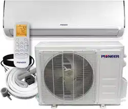
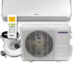
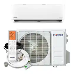
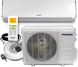
High Wall-Mounted Air Conditioner
The system is made up of two or more units connected together via insulated copper pipes
and an electrical communication cable. The indoor unit is mounted onto one of the walls in
the room that is to be conditioned. The outdoor unit is installed on the ground outside or on
the wall of the dwelling using suitable mounting brackets.
Note: The illustrations above are only intended to be a simple diagram of the appliance, and may not fully
correspond to the actual appearance of the system. Technical data is printed on the system’s labels.
Page 6
1
2
3
4
5
6
7
8
910
11
12
13
14
15
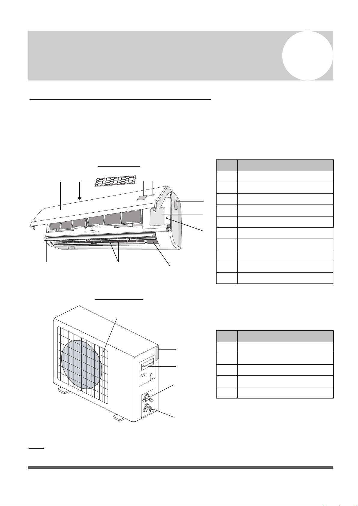
INDOOR UNIT
OUTDOOR UNIT
No.
Description
1
2
3
4
5
Front Panel
Anti Dust Filter
LED Display
Signal Receiver
Indoor Unit Rating Label
6
7
8
9
10
Terminal Block Cover
Emergency (Manual) Button
Ionizer Generator (Optional)
Deflectors
Airflow Direction Louver
No.
Description
11
12
13
14
15
Air Outlet Grille
Outdoor Unit Nameplate
Terminal Block Cover
Gas (Suction) Line Valve
Liquid Line Valve
Note: Serial Numbers are typically located behind the
electronic control box cover cap of either unit.
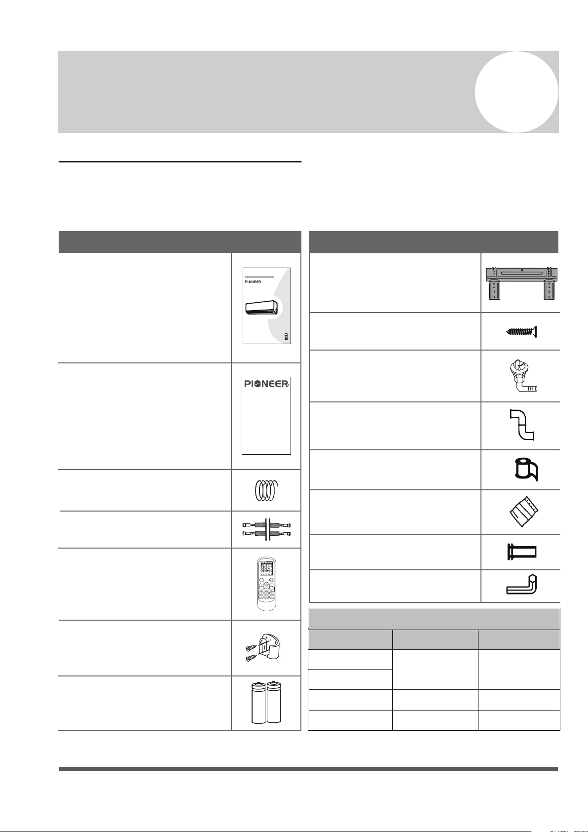
2
Included Accessories
1x Installation and Owner’s Manual
1x 16 ft. Communication Cable
SPLIT-TYPE ROOM AIR CONDITIONER
CS78421-548-754
IMPORTANT NOTE:
Read this manual carefully before installing
or operating your new air conditioning
unit. Make sure to save this manual for
future reference.
Installation and
Owner’s Manual
Page 7
Name
Appearance
1x 16 ft. Insulated Copper Pipe
1x Remote Controller
1x Remote Controller Holder
2x Remote Controller Batteries
1x Warranty Card
1x Indoor Unit Mounting Plate
1x Condensate Drain Hose
Name
Appearance
1x Wrapping Tape
1x Wall-Hole Packing Sealant
1x Wall Sleeve
1x Allen Wrench
1x Set of Mounting Plate Screws
1x Plastic Drain Joint Plug
Connecting Pipe Diameters
9000
12000
18000
24000
BTU Capacity
Liquid Line
Gas Line
1/4”3/8”
1/2” 1/4”
5/8” 1/4”
Accessories and Components:
The air conditioning system comes with the following accessories. Use all of the installation
parts and accessories to install the air conditioner. Improper installation may cause the
equipment to fail, or result in water leakage, electrical shock, or fire.
1. Unless this high quality product is registered properly as soon as it is put in service, all references made in this document to the term “warranty” solely refer
to the Basic Warranty, as further dened below. If this high quality product is registered properly as soon as it is put in service, all references made in
this document to the term “warranty” refer to the Standard Warranty, also as further dened below.
2. Warranty is provided by Parker Davis HVAC International, Inc. (hereinafter referred to as PD), the supplier of Pioneer® branded Split System Heat
Pump Products (hereinafter referred to as Products), covering all parts of the Products, subject to the following details:
a. Types of Installations: Warranty applies to all Products, installed in a residence. Warranty also applies to Products classied as light
commercial Products, installed in commercial properties.
b. Product Registration: Registration is not required for the availability of the Basic Warranty. Warranty registration is strongly urged and required
for the validity of the Standard Warranty. To register the Product, within one week after the Product is properly installed, ll out the warranty
registration card packed with the Product and send it in as instructed in the form OR conveniently register online at www.pdhvac.com and use the
registration link.
c. Exclusions to Warranty Coverage: Warranty does not apply to any Product that:
i. Are installed outside the United States of America.
ii. Are operated in unoccupied structures or used for purposes other than comfort cooling / heating.
iii. Are residential Products, but installed or used for commercial purposes.
iv. Has been removed from the place it was originally installed and reinstalled at another place.
d. Warranty Coverage: The warranty covers the parts of the Products, which may become defective due to the quality of the materials or
workmanship, under normal use and proper maintenance.
e. Warranty Does not Cover: PD is not responsible for any warranty claim due to:
i. Damages or repairs arising as a result of a faulty installation or wrong application.
ii. Damages or repairs arising from any external perils, out of PD’s control, such as res, storms, accidents, oods, broken or frozen water
pipes, electrical surges, input power with under or overvoltage, lightening or existence of corrosive substances nearby.
iii. Damages or repairs arising from use of non-compatible parts, alterations, modications or improper applications.
iv. Necessary maintenance required for the proper operation of the equipment, such as cleaning of all air lters, heat exchangers, fans and
blowers, any necessary lubrication of internal components and maintenance of external accessories.
v. Damages or repairs needed because of using parts, supplies or other add-on components that are not supplied by or approved for use by
PD.
vi. Damages or repairs as a result of improper use, poor maintenance, wrong operation or improper service.
vii. Changes that can be considered cosmetic, not aecting the systems performance, including but not limited to small n damages.
viii. Resetting of power or the circuit breakers and replacement of other types of fuses, both internal and external.
ix. Any damages of repairs caused by the use of dirty, recycled, wrong type or unapproved refrigerants and lubricants.
x. Damages or repairs due to moisture, air, dust, sand, dirt, etc., that have been allowed into the system by improper handling of system parts
and components during installation.
xi. Damages or repairs caused by continuing use the Product, after a malfunction has been noticed or indicated at the display module,
through an error code.
xii. Damages or performance issues due to improper matching, Product selection, under-sizing, over-sizing, improper installation or misuse.
f. Warranty Begin Date: Warranty begins on the date of installation and commissioning of the Product, in existing residences and commercial
buildings and on the date of sale of the dwelling, for the new residential construction to the rst buyer. However, the warranty beginning date cannot
exceed a date, further than 6 months following the manufacturing date of the Product as coded in the serial number. Warranty is provided only to the
rst original owner of the Product, where it is originally installed, and is not transferable to the subsequent owners.
g. Warranty End Date: Products that have not been registered as instructed above are covered under the Basic Warranty. The Basic Warranty lasts
for a period of up to one year. Products that have been properly registered as instructed above will be covered under Standard Warranty. The
Standard Warranty lasts for a period of up to ve years as further explained below in detail and only as long as the original registered owner, own
and reside in the dwelling, or operate the business in the property, in which the Product had been originally installed.
h. Remaining Warranty: Any part, component or Product that was replaced under the terms of the warranty will be covered under the same
warranty and only for the duration in which the original warranty for the Product is applicable, as commenced on its begin date.
i. Warranty Procedure: PD will furnish a new or remanufactured replacement part, without any charge for the part itself, for the replacement of any
part that has been determined to have failed, by PD at its sole discretion, due to defects in its materials or workmanship under standard use and
proper maintenance. Associated shipping costs for the replacement parts may also be covered at PD’s expense, at its own discretion and under
certain conditions, while the shipping method used will be solely determined by PD. Otherwise, the payment of the shipping costs for the part will be
the sole responsibility of the owner of the Product. PD reserves the right to ask the owner of the Product to return the failed part to PD, before
or after a replacement part may be sent out.
j. Labor cost, materials and other costs: Any labor costs and/or the costs for the supplies or materials used or purchased in the eld for the
replacement of the defective part, remain the responsibility of the owner. No other costs, involved in diagnosis, lodging, transportation, servicing, repair,
replacement, installation, removal, shipping, etc., are to be covered under the warranty.
k. Refrigerant: Any costs related to charging, recharging, adjustment, or removal of the refrigerant, and the cost of the refrigerant itself, are not
covered under any circumstances. All Products go through vigorous quality controls at various stations and leave the factory in perfect working
and sealed condition. Products are individually tested in highly sensitive helium vacuum chambers for existence of refrigerant leaks. Therefore PD
does not cover any claims related to the lack of refrigerant in new Products, discovered upon arrival, or during installation, as well as subsequent
refrigerant losses occurring at any time afterward
LIMITED PARTS WARRANTY
Pioneer® Brand Split System Heat Pump Products
© 2022, PARKER DAVIS HVAC INTERNATIONAL INC.
Page 8
Indoor Unit Overview
3
Owner’s
Manual
3
1
2
54
4
2
3
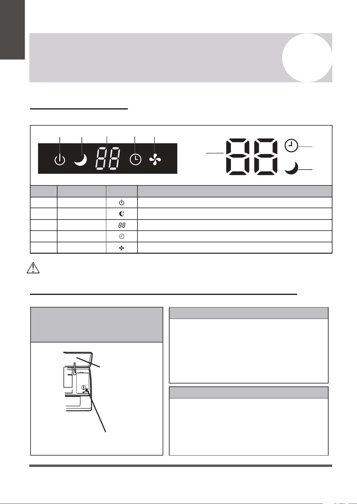
No.
Description
SymbolLED Icon
1
2
3
4
5
Indicates that the unit is currently powered onPOWER
SLEEP
TIMER
RUN
Temp. Display
Indicates that the system is currently in SLEEP mode
Displays the current set temperature or any error codes
Indicates that the TIMER function has been set
Indicates that the fan is currently on and running
The shape and position of switches and indicators may vary according to the model, however the functions remain the same.
There may be variances between the amount of digits that are shown on the remote (3) vs. the amount on the indoor unit (2).
Front Panel Display
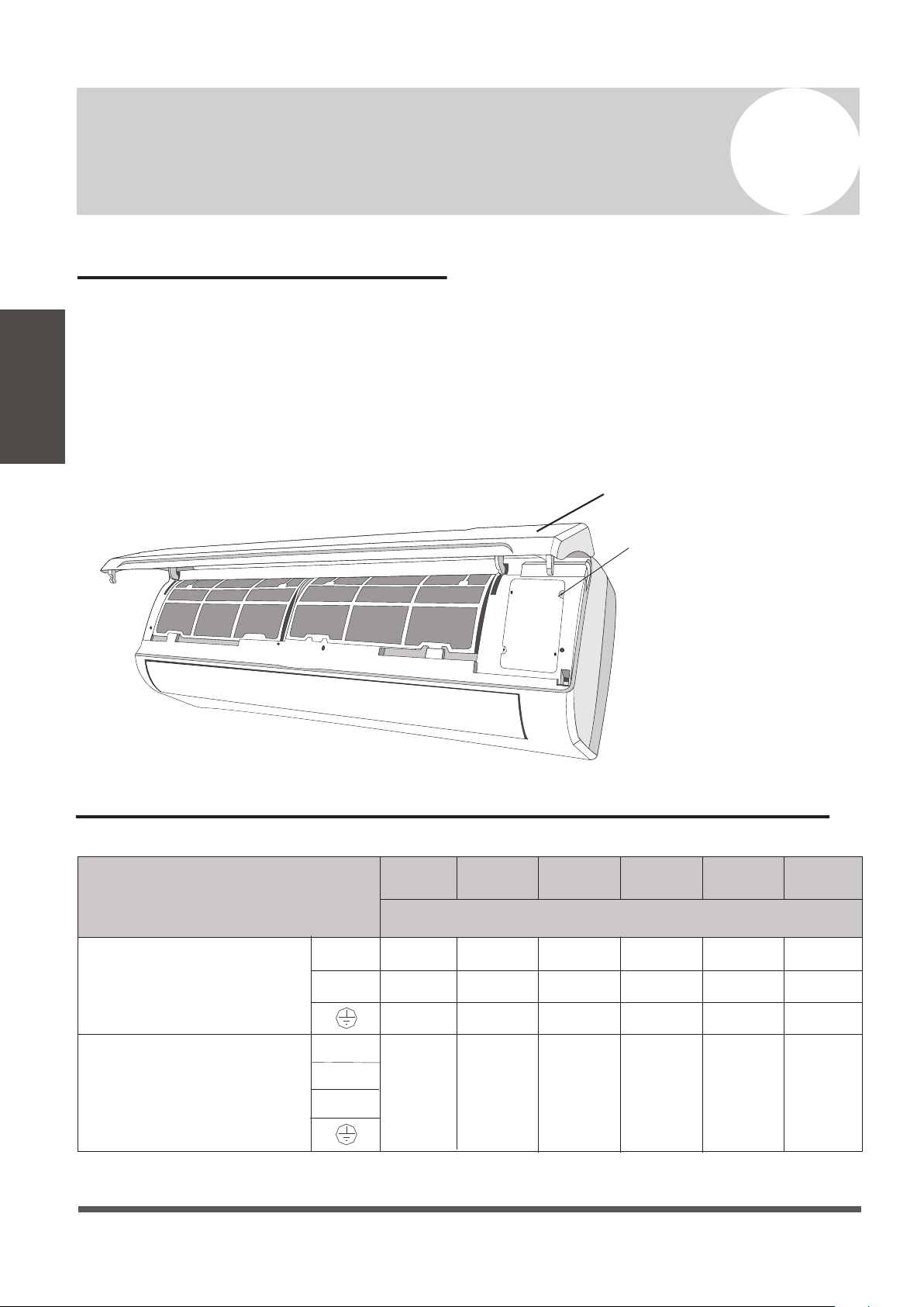
Emergency Manual Button And Auto-Restart Function
Emergency
Button
Front Panel
Emergency Manual Button
If the remote controller fails to operate the system, proceed as follows:
• Open and lift the front panel up at an angle to gain access to the
emergency button.
• Press the manual button once to start the unit in COOL mode.
• Press the button again within 3 seconds to start the unit in HEAT mode.
• Press a 3rd time within 5 seconds to turn off the unit.
Auto-Restart Feature
This appliance is programmed with an auto-restart function.
In case of sudden power failure, the control module will remember the
settings configured before power loss.
When power is restored, the unit will restart automatically, and will be
set to the previous settings, which were preserved with this memory
function.
The emergency button is located at
the terminal block cover of the unit
under the front panel.
Page 9
Owner’s
Manual
Operating Instructions
The display and some features of the remote control may
vary according to the model of the system.
The shape and positions of the buttons and indicators may
vary according to the model of the system, but the features
and functionality would remain the same.
The unit will confirm the successful reception of each button
command with a beep.
4
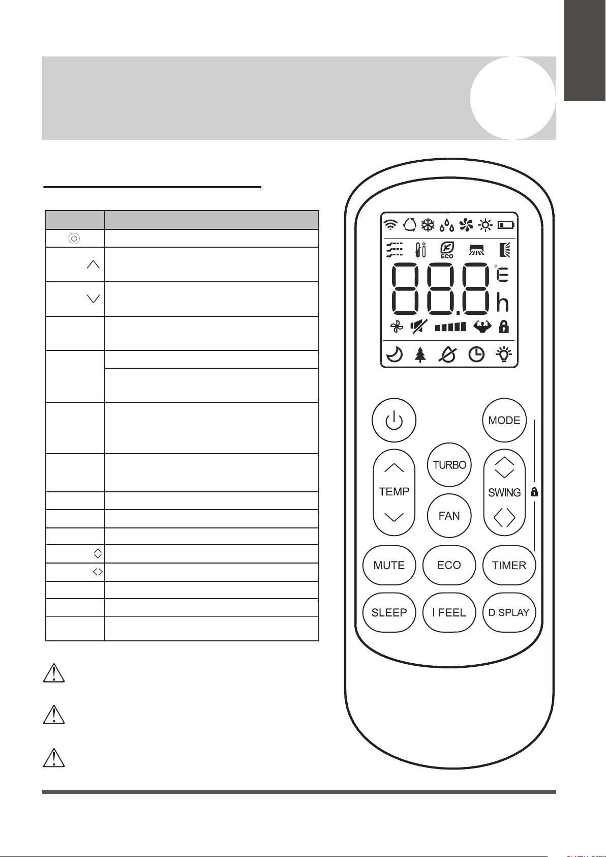
Remote Buttons Overview
Button Description
Turns the air conditioner on or off
Activates/deactivates the ECO feature
Configures the automatic on/off times
Toggles the system’s Sleep Mode
Turns the LED display on or off
Activates the up-down louver motor
Activates the left-right louver motor
Puts the system into silent mode
Press MODE+TIMER for child-lock
Activates the system’s Follow Me mode
Long press to activate the 46°F “Away
from Home” freeze protection setting.
Decreases set temperature, set timing,
or navigates the functional menu
Increases set temperature, set timing,
or navigates the functional menu
Selects the mode of operation (Auto,
Cool, Dry, Fan, and Heat modes)
Configures the fan speed
(Auto, Low, Mid, and High)
Activates/deactivates the TURBO
feature, which allows the system to
reach set temperatures quicker
MODE
TEMP
TEMP
DISPLAY
SWING
MUTE
LOCK
I FEEL
TURBO
FAN
TIMER
SLEEP
ECO
SWING
Page 10
4
NOTE ON ILLUSTRATIONS
The illustrations in this manual are strictly for explanatory purposes. The actual display and some
functions of the remote controller may vary according to the model purchased.
Operating Instructions
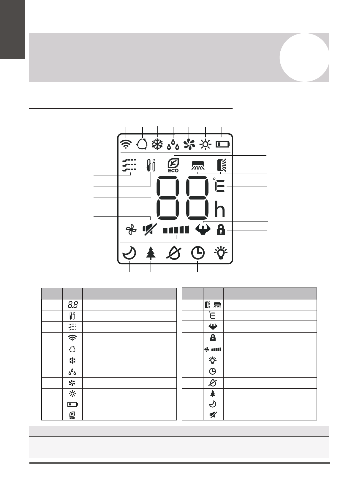
No.
Description
Icon
10
3
4
5
6
Auto Mode
Cooling Mode
Signal Transmit Indicator
Dry Mode
Fan Only Mode
7
8
9
Heating Mode
ECO Mode
Unit of Temperature (°C/°F)
Remote Controller LED Screen and Icons
Owner’s
Manual
No.
Description
Icon
2
1
12
11
Temperature Indicator
Battery Level Indicator
Mute Function
Turbo Mode
Child Lock Indicator
15
16
18
17
13
14
21
22
19
20
Directional Swing Indicators
Timer Active Indicator
LED Display On/Off
Health Funct. (Some Models)
Anti-Mildew (Some Models)
Sleep Function
I Feel/Follow Me Mode
Gentle Wind (Some Models)
Fan Speed (Auto or Fixed)
4
5
6
7
8
9
10
1
2
3
11
12
13
14
15
16
192021 1718
22
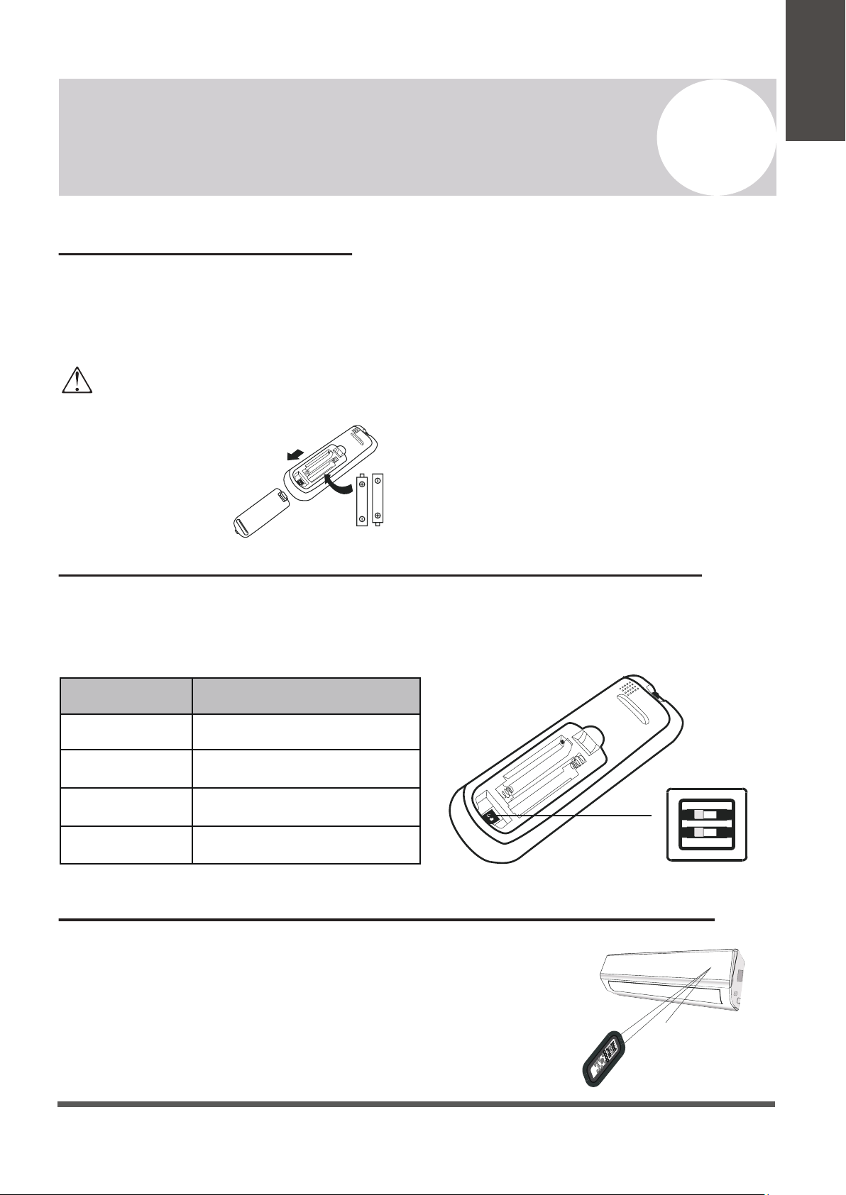
Depending on the system, the control type (Cooling Only or Heat Pump) and the unit of
Temperature (°C or °F) can be configured using the manual dip-switches below the battery
compartment. Operate as below:
Page 11
4
Operating Instructions
Owner’s
Manual
Replacement of Batteries
Remove the battery cover from the rear of the remote controller, by sliding it downward in
the direction of the arrow as depicted below. Install batteries according to the depicted
directions (+ and -) as shown on the remote controlller. The cover then slides back into place.
Configuring Remote Controller Settings (some models)
Use 2x AAA batteries. Do not use re-chargeable batteries. Replace old batteries with new ones of the same type when the
display is no longer legible. Do not dispose of batteries as unsorted municipal waste. Disposal of such waste separately
for special treatment is necessary. If the system will not be used for a long time, remove batteries to prevent leakage.
Note
Please remove batteries to avoid
leakage damage when not
being used for a long time.
Signal
receptor
DISPLAY 3D
HEAL
TH
Y
ON/O
FF
SWING
FAN
TIMER
SU
PER
SL
EE
P
M
ODE
EC
O
CLOCK
Operating the Remote Controller Sucessfully and Safely
• Ensure no objects come between the remote controller and signal
receptor of indoor unit.
• Keep the remote at least 3 ft away from televisions and other
electrical appliances.
• Always direct the remote controller toward the air conditioner.
• Don’t leave the remote exposed to sunrays.
Switch Position
°C
°F
COOL
HEAT
Functional Result
Temp. Units are Celsius
Temp. Units are Fahrenheit
Cooling Only Operation
Heating + Cooling Operation
4
Operating Instructions
Page 12
CAUTION
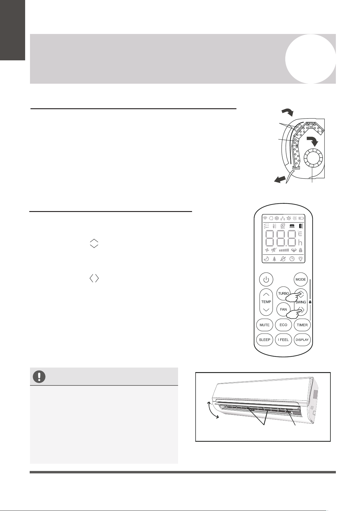
Regarding the Airflow of the Indoor Unit
The air that is pulled in by the fan (the “return air”) enters the
grille and is passed through the filter. It is then
cooled/dehumidified/heated through the heat exchanger.
The direction of the air output is manipulated up and down by the
motorized louver, and left to right via manually controlled vertical
deflectors. Some models may come with “dual-swing” capability,
which offers both a horizontal and vertical motorized air flow swing.
Controlling the System’s Airflow
1. Pressing the SWING buttons activates the louver.
• Press the Swing button to trigger the horizontal
flaps to swing up and down. Press this button again
to stop swing movement at the current angle.
• Press the Swing button to trigger the vertical
flaps to swing left and right. Press this button again
to stop swing movement at the current angle.
2. If the vertical deflectors (which are located
underneath the flaps) are adjusted manually,
they can be used to fix the airflow in a certain
vertical position before turning the system on.
Owner’s
Manual
Filter
Heat
Fan
• Do not manipulate the louvers themselves
manually, or serious damage may occur.
• Deflector adjustments should be made
only when the system is switched off.
• Never poke fingers, sticks, or other
objects into the air inlet/outlet vents.
Horizontal
Flaps
Flap
Movement
Vertical
Deflectors
Note: Some models possess a self-clean mode which is activated
by pressing and holding these two buttons together.
Page 13
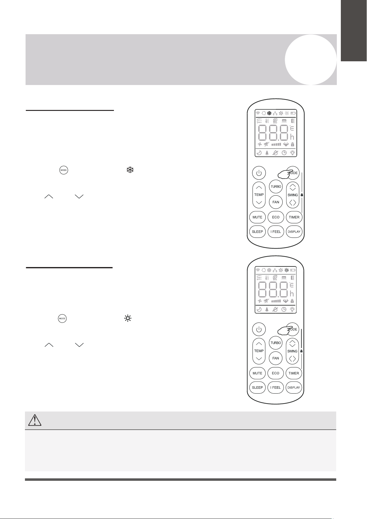
COOLING Mode
Cooling mode allows the air conditioner
to cool the room while also reducing
the humidity of the air in the room.
To put the system into cooling mode,
press the button until the symbol
appears on the remote’s display.
The and buttons can then be used to
set a temperature lower than that of the room.
4
Operating Instructions
Owner’s
Manual
HEATING Mode
Heating mode allows the air conditioner
to heat the room.
To put the system into heating mode,
press the button until the symbol
appears on the remote’s display.
The and buttons can then be used to
set a temperature higher than that of the room.
NOTE
In heating mode, the appliance will periodically enter a defrost cycle, which is essential in order to clean frosting
off the condenser and recover heat exchange capability. This process is normal and lasts for 2-10 minutes.
During defrosting, the indoor unit’s fan will cease operation. After the cycle is completed, the system will resume
its normal heat mode operation automatically. Press ECO 10 times within 8 seconds to trigger a forced defrost.
Page 14
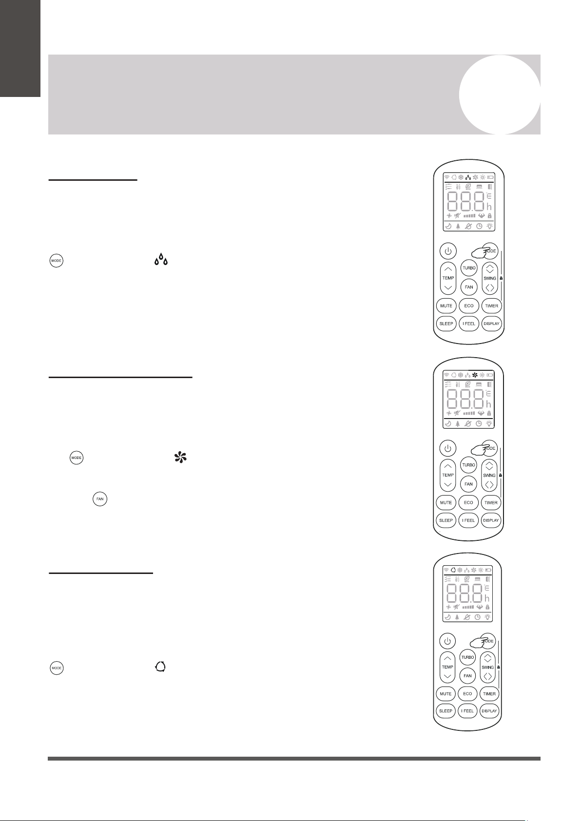
DRY Mode
Dry mode is a limited function that can rapidly
reduce the humidity/moisture of the room.
To put the system into dry mode, press the
button until the symbol appears on the
remote’s display.
An automatic preset of this mode is then
activated.
4
Operating Instructions
Owner’s
Manual
FAN-ONLY Mode
Fan-only mode is used to set the system to use
only air ventilation and no heating or cooling.
To put the system into fan-only mode, press
the button until the symbol
appears on the remote’s display.
Use the button to then set the desired fan
speed.
AUTO Mode
Auto mode will let the system determine the
running configuration based on the set
temperature and the current room temperature.
To put the system into AUTO mode, press the
button until the symbol appears on the
remote’s display.
Page 15
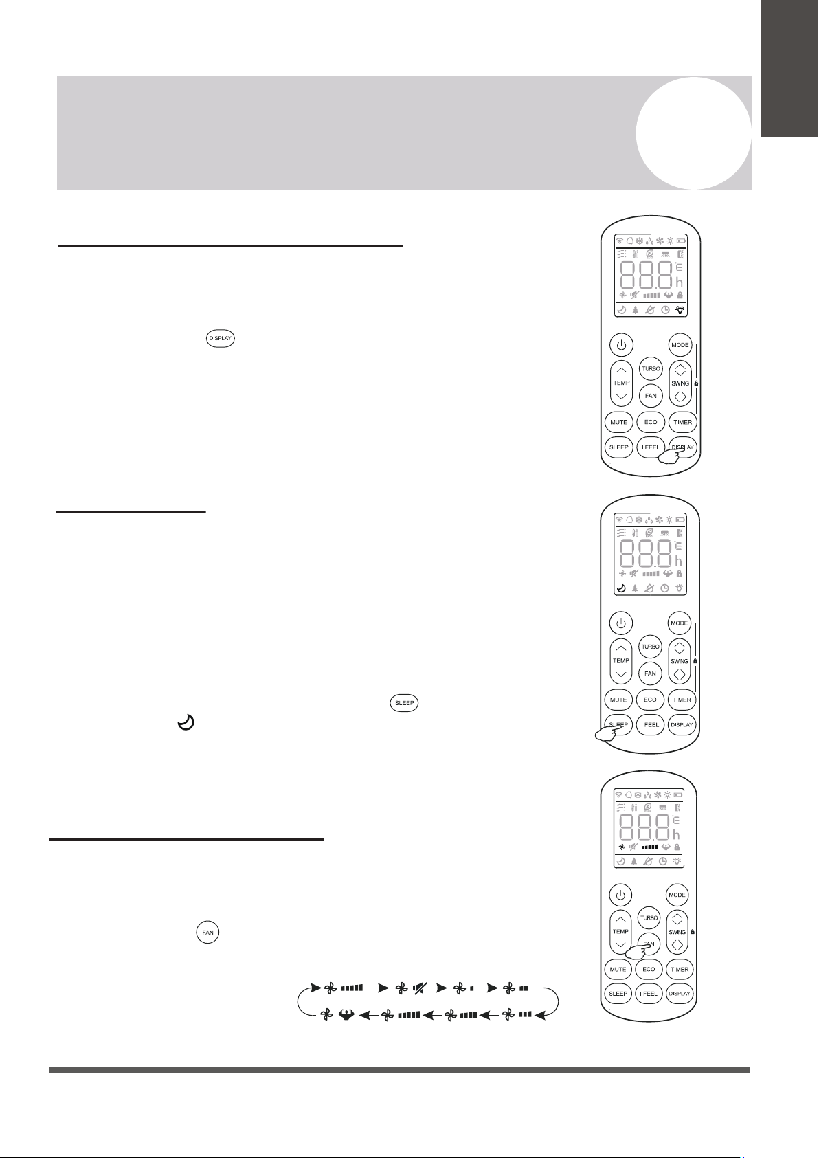
Turning the Display On or Off
The LED display on the front panel of the
system can be turned on or off as desired.
To do so, press the button in order to
switch off the LED display on the front panel.
This button can be pressed again to turn the
LED display back on.
4
Operating Instructions
Owner’s
Manual
SLEEP Mode
Sleep mode is generally meant for periods of lower
cooling requirements, such as during typical sleeping
hours. This mode will result in decreased energy use,
and can only be activated via remote control.
After 10 hours in sleep mode, the air conditioner will
revert back to the previously set mode.
To put the system into sleep mode, press the
button, and the symbol will appear on the display.
Press this button again to exit from this mode.
Changing the Fan Speed
The fan speed can be changed between AUTO, LOW, MID,
and HIGH speeds.
To do so, press the button. The running fan speed can
then be set. It follows the cycle of:
Auto>Mute>Low>Low-Mid>
Mid>Mid-High>High>Turbo
(Flash)
Page 16
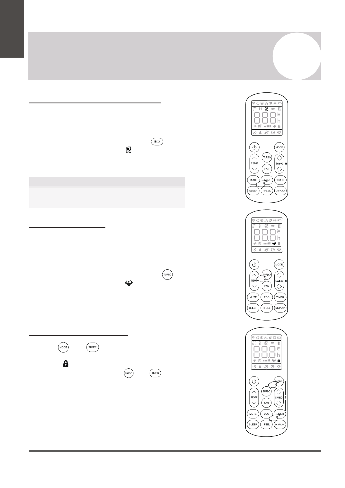
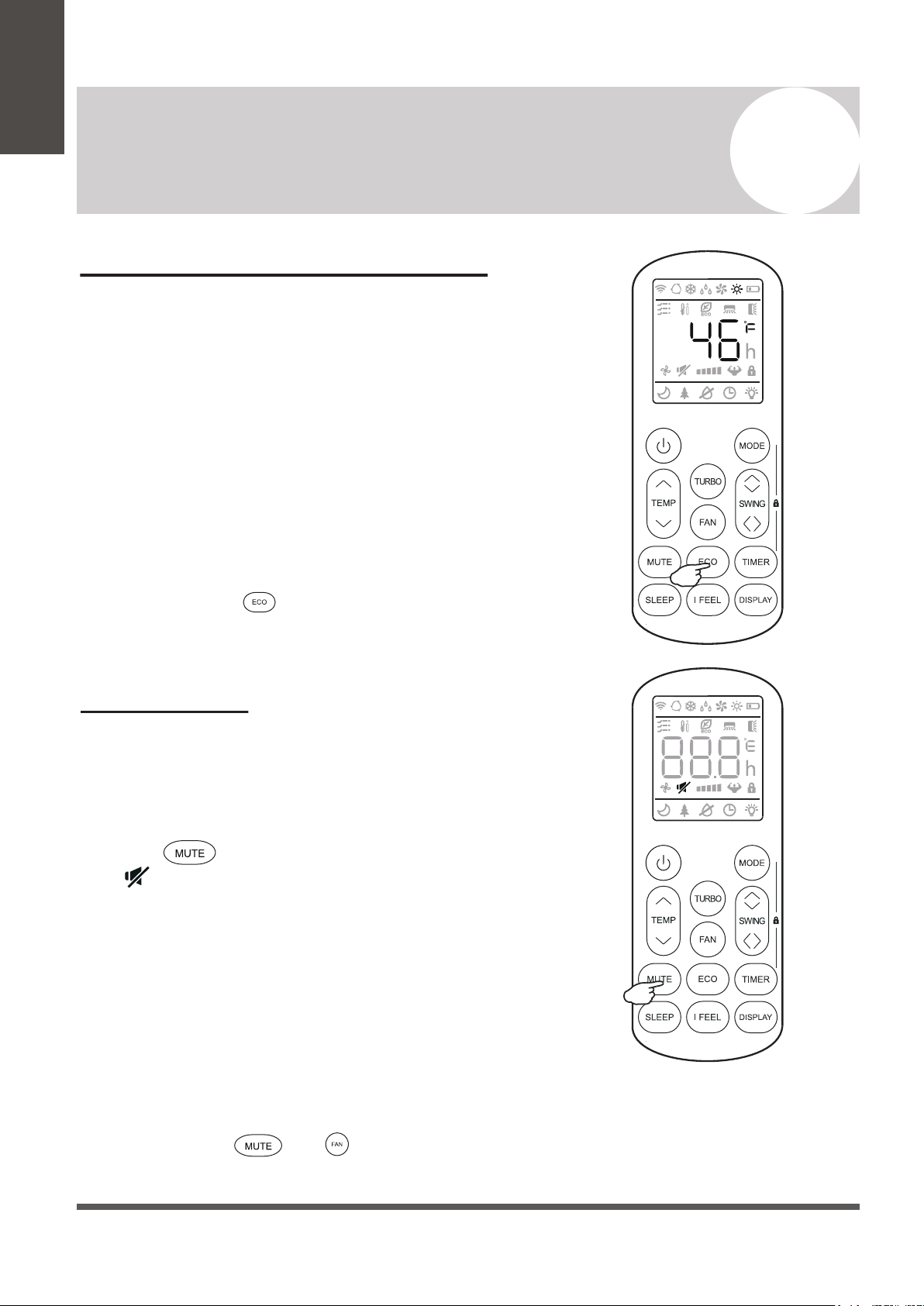
Energy Saver (ECO) Option
In this mode, the appliance will automatically
manage the operation in order to save energy.
To turn the ECO feature on, press the
button on the remote, and the icon will
appear. The system is now running in ECO,
and the process can be repeated to turn it off.
4
Operating Instructions
Owner’s
Manual
NOTE
The ECO feature is available in both COOLING
and HEATING modes.
TURBO Option
Child-Lock Function
In this mode, the appliance will operate using the
highest fan speed in order to maximize output
and reach the set temperature the quickest.
To turn the TURBO feature on, press the
button on the remote, and the icon will
appear. The system is now running in TURBO,
and the process can be repeated to turn it off.
Pressing and buttons together will acti-
vate the child-lock function. When this function is
active, the icon will be displayed, and no single
button will be active. Press the and buttons
together once more to de-activate the child-lock
function.
Page 17
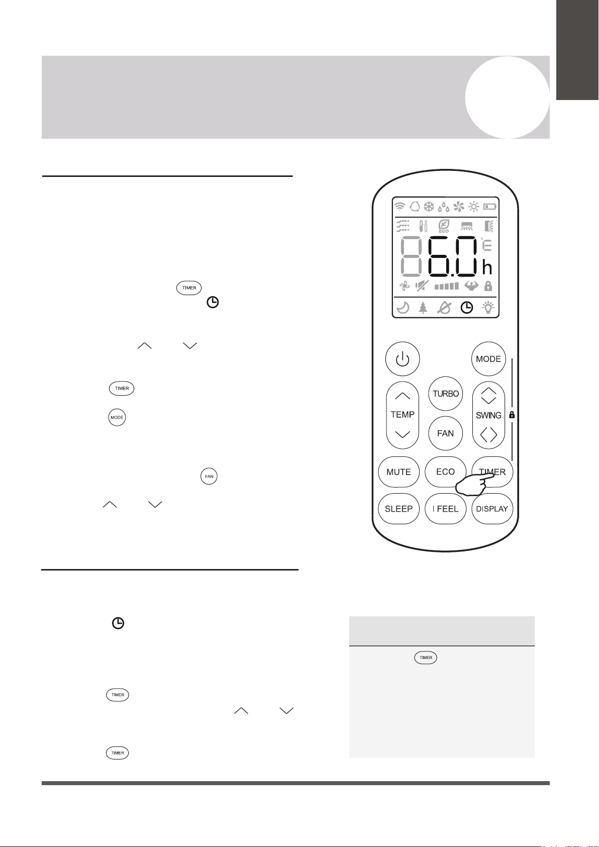
NOTE Regarding Timers
• Press the button to cancel
at any time in Timer Off.
• The programming will cancel
if no buttons are pressed after
5 seconds. This may require
restarting the process.
Using the Timer - TIMER ON
The TIMER feature allows you to set a time delay for
the system to turn itself on or off.
To set a time delay for the system to turn itself on in X
amount of hours:
1. Begin by pressing the button while the
system is powered off. The symbol will then
display flashing. The default setting is 6.0 hours.
2. Use the Temp and buttons to set the
needed time delay in 30 minute increments.
3. Press the button a second time to confirm.
4. Press the button to select the desired
operating mode that the unit should start up in.
5. Set the desired fan speed that the unit should
start up in by pressing the button.
6. Use the and buttons to set the desired
operation temperature. The unit is now primed.
Using the Timer - TIMER OFF
The TIMER OFF feature allows the appliance to
turn itself off after X amount of hours have passed.
The symbol will appear. To set a time delay for
the system to turn itself off in X amount of hours:
1. Confirm that the appliance is on and running.
2. Press the button to enter the prompt for
switching off the system. Use the and
buttons to configure the time delay setting.
3. Press the button again to confirm. It can
also be pressed once more to cancel the setting.
4
Operating Instructions
Owner’s
Manual
Page 18
4
Operating Instructions
Owner’s
Manual
46°F Freeze Protection Function
This feature is meant to be used to prevent
freezing while the user is away from home. When
turned on, it sets the system to keep a temperature
of 46°F. If the unit is in standby, then the setting
will automatically start the heating mode when the
room temperature is equal to or lower than 46°F.
It will set the system back to standby when the
room temperature reaches 48°F.
If the room temperature is ever 64°F or higher,
then the appliance will cancel or prevent this
feature automatically.
Press and hold the button for 3 seconds to
activate this feature. Repeat this to de-activate.
MUTE Mode
When the system is muted, the remote controller will
display AUTO fan speed, and the indoor unit will
operate at its lowest fan speed in order to
minimize operation noise.
Press the button in order to activate this mode.
The icon will display to indicate that the system is
muted.
This mode can be cancelled by pressing either the
FAN, TURBO, or SLEEP buttons.
Note: The MUTE feature cannot be activated when the
system is in DRY mode.
Note: Some models come equipped with a “Gentle Wind”
function, where the unit will auto-close the vertical
louver, and provide a softer air breeze. Activate this
by pressing the and buttons together for 3
seconds.
Page 19
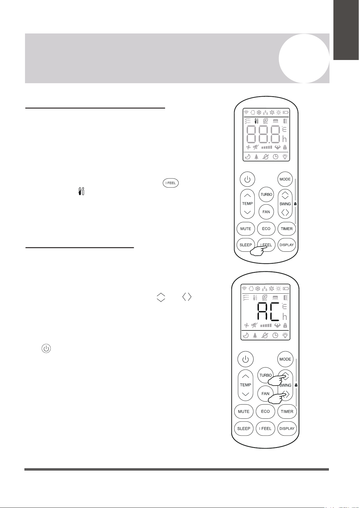
I FEEL - To Ensure Comfort
The I FEEL feature enables the remote to act as
the temperature sensor and relay the current air
temperature of where the remote is physically
placed within the room. In some cases, this can
aid with reducing thermal drift between the set
temperature and the actual room temperature.
In order to activate this feature, press the
button, and the icon will appear on the display.
Note: The I FEEL feature will automatically de-activate
itself 2 hours later.
SELF-CLEAN Feature
This feature helps carry away accumulated dust,
dirt, bacteria, and other microbial contents away
from the indoor evaporator.
To activate this feature, press the Swing and
buttons together until a beep is heard from the unit,
and AC is displayed on the unit and remote.
This procedure will run for approximately 30
minutes, before returning to the preset mode.
The button can be pressed to cancel this feature
during the process. Two beeps will be emitted from
the machine when it is finished, or cancelled.
This procedure can result in some uncommon noise
coming from the machine. This noise is normal as a
side effect of the plastics expanding and contracting
due to reactions with heat and cold.
It is recommended to use this function only when
indoor temperature is under 86°F and outside
temperature is between 41°F and 86°F.
It is suggested to run this feature once every 3 months.
4
Operating Instructions
Owner’s
Manual
Page 20
NOTE
After stopping and restarting the air conditioner, or after the mode is changed during operation, the system does
not restart immediately, and will come on when three minutes have elapsed (as a protection for the compressor).
4
Operating Instructions
Owner’s
Manual
An Important Note Regarding Operating Temperatures
The system is designed to run within a certain range of temperatures, which are listed below.
There are built-in protections with the system that may stop the appliance when the ambient
temperatures goes outside of these ranges.
Inverter Air Conditioner
Temperature
Operating
Mode
Current Room Temperature
Ambient Outdoor Temperature
COOLING Mode
63°F - 89°F
5°F - 127°F -13°F - 86°F
59°F - 127°F
32°F - 86°F
63°F - 89°F
HEATING Mode
DRYING Mode
Full system-rated capacity and efficiency is obtained at the standard rating conditions as developed by
the testing and rating agencies. Deviations from the rating conditions, especially the atmospheric
conditions, will be compensated by the variable speed compressor, within certain limitations.
Heat pump systems function by exchanging energy, in the form of heat, between the indoor air and
the outdoor ambient air (atmospheric). The system’s net cooling or heating capacities and efficiencies
change by atmospheric conditions, as well as the indoor air conditions (such as temperatures and
humidity levels).
Capacity of the system required for a specific area or application must be determined professionally
using detailed calculations, which are based on several internal and external factors.
To further optimize the performance of your unit, be sure to do the following:
• Keep doors and windows closed.
• Limit energy usage by using TIMER ON and TIMER OFF functions.
• Do not block air inlets or outlets.
• Regularly inspect and clean air filters.
In addition to the filters, the interior of the indoor unit itself as well as the inner coil should be
inspected every season. The front panel can be disconnected and removed from the top hinge
where the pegs connect. This will allow for easier inspection of the interior and behind the air
filters. The interior should be cleaned with damp cloth and neutral soaps. Do not use any sort
of aggressive solvents or detergents. Only a soft cloth that is lightly damp should be used.
Periodic Maintenance Is Essential For The System!
Maintaining the air conditioner will ensure that is stays efficient. Before carrying out any sort
of maintenance, always ensure that the power supply to the system is turned off.
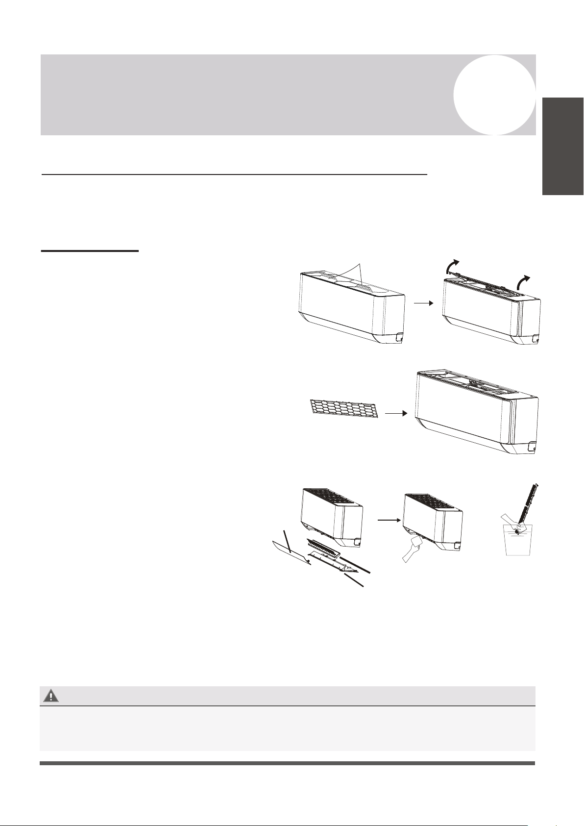
Indoor Unit
Anti-Dust Filters (Clean once every 2 weeks)
1. Approach the interior unit to reach the top
area, and grasp both the exposed handles.
2. Gently remove the single anti-dust filter by
pulling upwards and backwards as depicted.
3. The filter is washable and should be cleaned
with warm water (under 113°F).
4. Leave the filter to dry in a cool, dry place.
5. Afterwards, re-insert the filter into the same
location after it has sufficiently dried.
*Inner Bottom Air Components can be
cleaned and maintained similarly.
Any electrostatic or deodorizing filters, if installed, are not
washable and should be replaced once every 6 months.
Interior of the Indoor Air Handler
Page 21
5
Maintenance of the Air Conditioner
Maintenance
Instructions
Handles
BEFORE CLEANING OR MAINTENANCE
ALWAYS TURN OFF YOUR AIR CONDITIONER SYSTEM AND DISCONNECT ITS POWER SUPPLY
BEFORE PERFORMNG CLEANING OR MAINTENANCE. DO NOT SPRAY WATER DIRECTLY NEAR
THE INDOOR UNIT, AS IT CAN DAMAGE INSULATION AND ELECTRICAL COMPONENTS.
Anti-Dust Filter
+
Louver
Deflector Assembly
Bottom Plate
Wash with room
temperature water
Indoor Unit Installation Location Selection
Follow the below best practices for selecting an optimal space for installation the indoor unit:
• DO NOT install the unit on a wall that is subject to vibrations.
• DO NOT install the system near sources of heat, steam, or flammable gases.
• DO NOT install the indoor unit in a location that is exposed to direct sunlight.
• DO ensure that the inlet and outlet vents are not obstructed. The system should be able to
output air all across the room.
• DO minimize the distance between the indoor and outdoor unit and install the unit in a
place where connecting the indoor and outdoor unit will be as simple as possible.
• DO install the unit on a strong wall and where it is easy to drain the condensate water.
• DO install the unit in a location where it will be easy to service the machine and perform
any necessary maintenance.
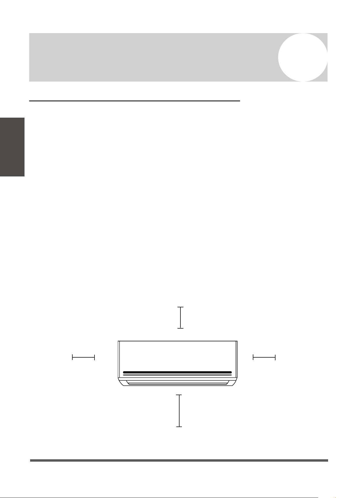
• DO obey the following tolerances depicted in the illustration below:
Page 22
6
Indoor Unit Installation Instructions
Indoor Unit
Installation
10-15 cm (4-6in)
or more
2.0 m (80 in) or more
10-15 cm (4-6 in)
or more
10-15 cm (4-6 in) or more
Installation Diagram
Before proceeding, it is important to consider the following height and length restrictions:
Before starting the installation, decide on the position of both the indoor and outdoor units.
Take into account the minimum clearance requirements for both the indoor and outdoor
units, which can be found in their respective sections of this manual.
Install the indoor unit inside the room to be air conditioned, avoiding corridors and
communal areas. Install the indoor unit at a height of at least 8 ft. off of the ground.
Page 23
6
Indoor Unit Installation Instructions
Indoor Unit
Installation
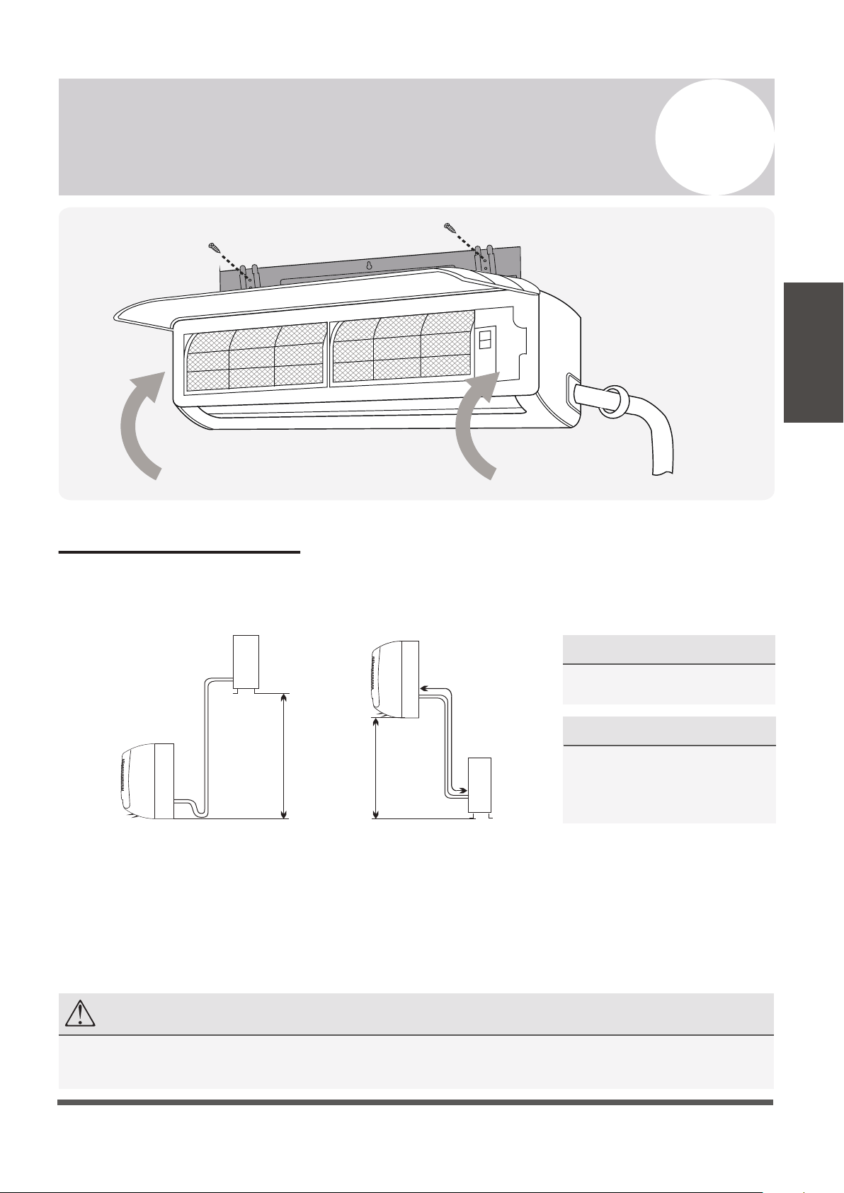
Outdoor Unit
Indoor Unit
Pipe length
is 50' max
Pipe length
is 50' max
Indoor Unit
Outdoor Unit
Height differential
must be less than 33 ft.
Height differential
must be less than 33 ft.
NOTE
Only persons and/or companies qualified and experienced in the installation, service, and repair of refrigerant
products should be permitted to do so. The purchaser must ensure the system is installed carefully and correctly.
For Systems of 18K and 24K BTU:
• The allowable height differential
increases to 49 ft.
• The allowable pipe length is 65 ft.
For Systems of 9K and 12K BTU:
• Follow the given constraints in the
figures to the left.
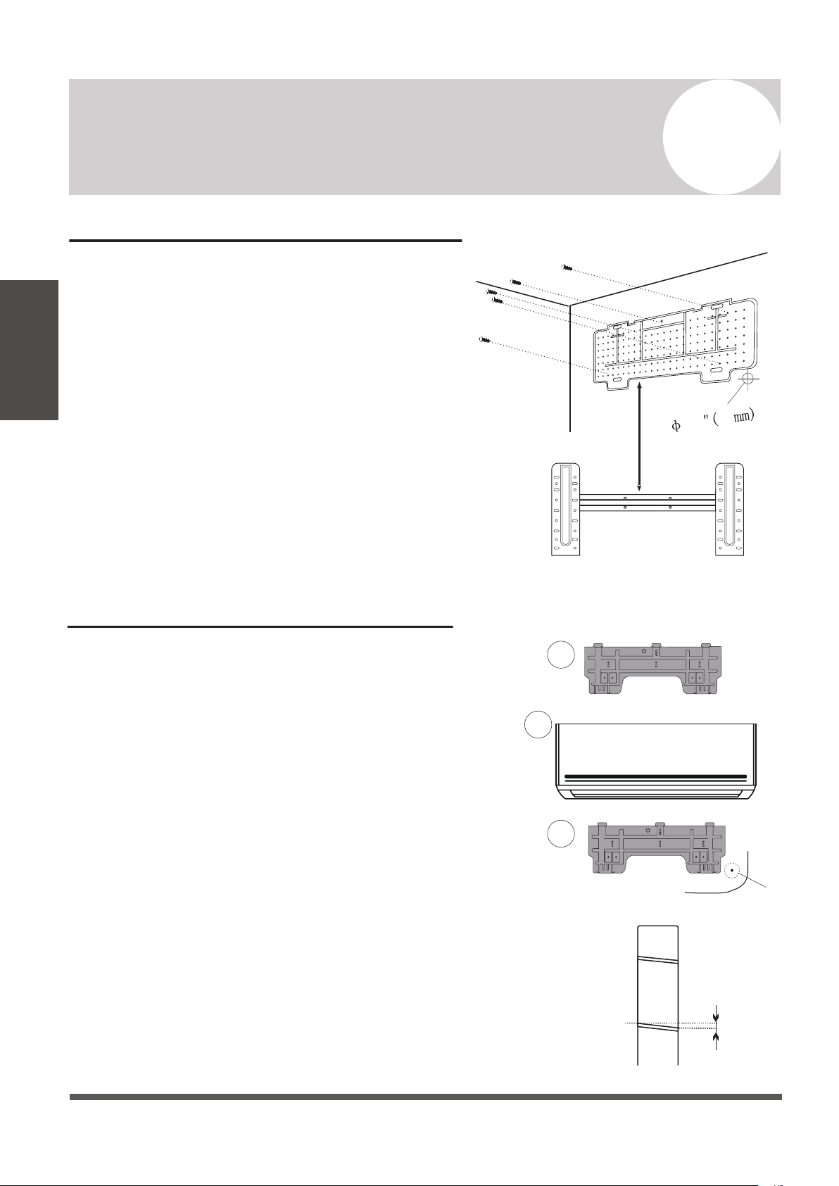
Installation of the Mounting Plate
1. Place the included mounting plate against the
wall where the system will hang that fulfills the
constraints on page 22. Use a level to ensure that
the plate is horizontally level.
2. Drill 1.3” deep holes for each screw to enter, the
locations are flexible but should be spaced well.
3. Insert the plastic anchors into each of the holes.
4. Fix the mounting plate to the wall by using the
included tapping screws. Check that it is secured.
Note: The actual appearance of the mounting plate
may differ slightly but the process is similar.
Drilling the Wall Hole for Piping
CHECK PAGES 43-44 FOR MOUNTING HOLE
GUIDELINES ACCORDING TO THE BRACKET.
1. With the mounting plate firmly affixed to the
wall, mount the indoor unit onto the mounting
plate temporarily in order to determine the
location of the wall hole in the next steps.
2. Using a pencil, lightly trace the bottom corner of
the indoor unit, depending on which side exit
the piping will go through (see Page 26).
3. Take the inside unit off of the plate, and make a
mark of where the hole will be (PG. 43-44), to ensure
ample clearance between the tracing and bracket.
4. Drill a 2.5” wall hole at a slight downward
angle using a core drill, being careful to avoid
wires, plumbing, and other sensitive materials.
The bottom of the inside hole should be ~1/4”
above the bottom of the outside hole.
Page 24
6
Indoor Unit Installation Instructions
Indoor Unit
Installation
Indoors
Outdoors
0.2
(5mm)
1
2
3
ø2.5”
If doing right side exit...
”
2.5 64
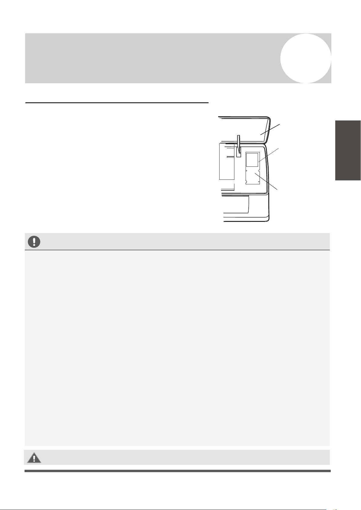
Electrical Connections - Indoor Unit
All systems will include a wiring diagram affixed to the
indoor unit. See Page 44 for more details.
1. Lift up the front panel of the indoor unit.
2. Remove the cover as indicated in the illustration.
3. For the electrical wiring, consult the circuit diagram
affixed to the elecrical cover.
4. Connect the cables to the wiring terminal by following
the numbering. Use wire gauge suitable for the
electrical power input. (see name plate on the unit).
Page 25
6
Indoor Unit Installation Instructions
Indoor Unit
Installation
BEFORE PERFORMING ELECTRICAL WORK, READ THESE REGULATIONS
1.
All wiring must comply with local and national electrical codes, and must be installed by a
licensed electrician.
2.
All electrical connections must be made according to the Electrical Connection Diagram
located on the panels of the indoor and outdoor units.
3.
If there is a serious safety issue with the power supply, stop work immediately. Explain your
reasoning to the client, and suspend all installation until the safety issue is properly resolved.
4.
Power voltage should be within 90-110% of rated voltage. Insufficient power supply can
cause malfunction, electrical shock, or fire.
5.
Connect power through fixed wiring, install a surge protector and a disconnect switch box,
and a dedicated circuit breaker with a capacity of 1.5 times the maximum current of the unit.
6.
A properly rated HACR-type fuse or circuit breaker that disconnects all poles and
has a contact separation of at least 1/8in (3mm) must be incorporated in the fixed wiring.
The qualified technician must use an approved circuit breaker or fuse.
7.
Only connect the unit to an individual branch circuit. Do not connect another appliance
to that outlet. This equipment requires its own dedicated and protected circuit.
8.
Make sure to properly ground the air conditioner.
9.
Every wire must be firmly connected. Loose wiring can cause the terminal to overheat,
resulting in product malfunction and possible fire.
10.
Do not let wires touch or rest against refrigerant tubing, the compressor, or any moving
parts within the unit.
WARNING:
BEFORE PERFORMING ANY ELECTRICAL OR WIRING WORK,
TURN OFF THE MAIN POWER TO THE SYSTEM.
Front Panel
Wiring Diagram
Terminal Block
Cover
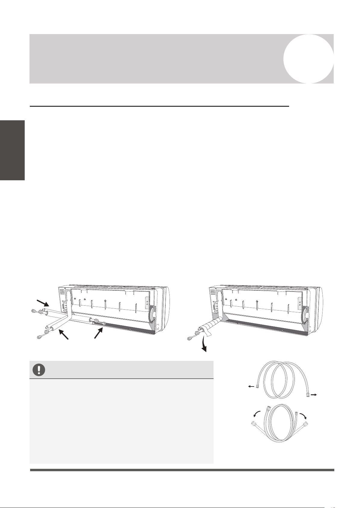
Preparing the Refrigerant Piping of the Indoor Unit
The piping “pigtails” pre-attached to the indoor unit can be run in 3 different ways as shown
in the illustration. Decide which type of configuration is most suitable before continuing.
By default it is routed for a left side exit as shown in #1. This method can either use the left
side knockout for a side exit, or a wall hole can be drilled on the left side of the unit’s rear.
Routing it straight through the back of the system (#2) will facillitate the connections to the
copper pipe extensions to be made outside. This is recommended to simplify the process.
#3 is a right side exit, but is not recommended as it involves a 180° bend of the piping, which
increases the risk of kinking or collapsing the lines dramatically. Bend slowly and cautiously.
If a side-exit is chosen, there are knock-out panels on either side of the unit that can be cut
out along the groove to provide a notch for the pipe to exit from. Use a cutter to do this.
For the method chosen, run the piping in the direction of the wall hole. Bind the copper
pipes, drain pipe, and power cables together with tape, with the drain pipe at the bottom so
that water can flow freely. Ensure that the bundle is exiting at a continuous downward pitch.
3
2 1
Downward
Inclination
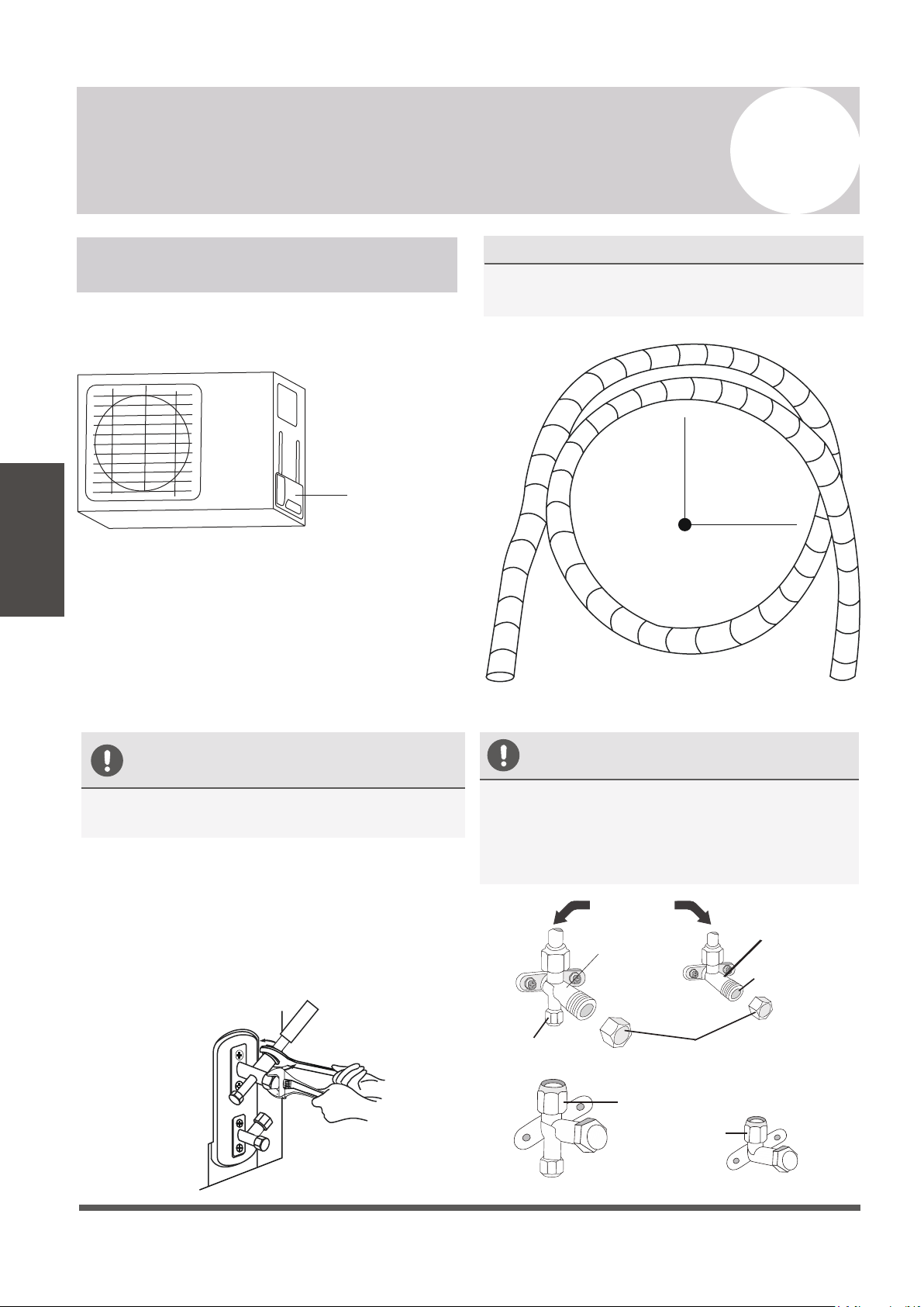
CAUTION
• Do not remove the cap from the pipe until it is time
to connect it, to avoid dampness or dirt from entering.
• If the pipe is bent/pulled too often, it will become stiff.
Do not bend the pipe more than three times at one
point. Be extremely careful not to kink any piping.
• When extending the coiled copper pipes, straighten
them by unwinding gently, as shown in the picture.
YES
NO
Unwind the coil gently
rather than pulling at ends
Page 26
6
Indoor Unit Installation Instructions
Indoor Unit
Installation
Connecting the Drain Hose
By default, the drain hose is attached to the left-hand side of
unit (”left” when facing the back of the unit). However, it can
also be attached to the right-hand side.
1.
To ensure proper drainage, attach the drain hose on the
same side that your refrigerant piping exits the unit.
2.
Attach any drain hose extensions (sold separately) to the
end of drain hose.
3.
Wrap the connection point firmly with Teflon tape to
create a good seal, and to prevent leaks.
4.
For the portion of the drain hose that will remain indoors,
wrap it with foam pipe insulation to prevent condensation.
5.
Remove the air filter and pour a small amount of water into
the drain pan to make sure that water flows from the unit
smoothly.
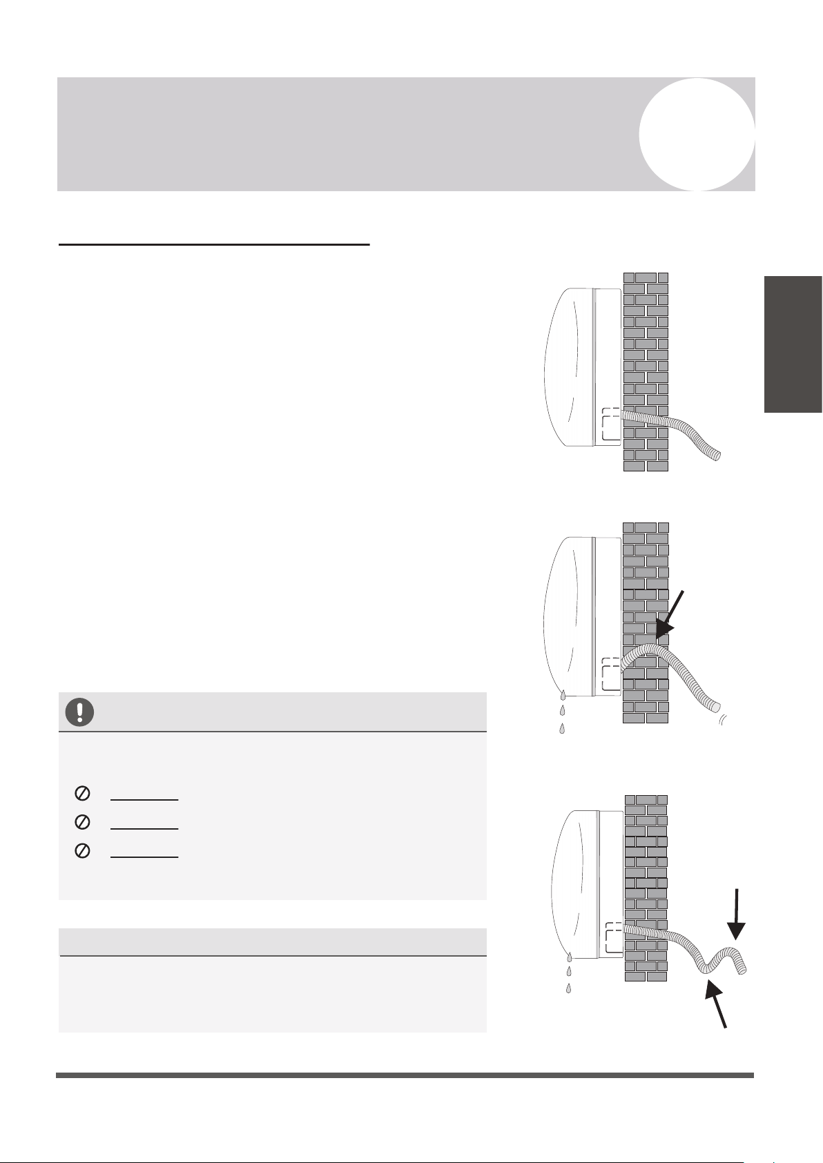
NOTE ON DRAIN HOSE PLACEMENT
Make sure to arrange the drain hose according
to
the illustrations.
DO NOT
kink the drain hose.
DO NOT
create a water trap (siphon).
DO NOT
put the end of the drain hose in
water or in a container that will collect water.
DUAL DRAIN HOLE LOCATIONS EXIST
The indoor unit has 2 drain connections on left and
right sides. Either one can be utilized. One side will
have a hose connected, while the other is plugged.
YES
NO
NO
Page 27
6
Indoor Unit Installation Instructions
Indoor Unit
Installation
Connecting the Signal Cable
Cable Wire Specifications (For Uncommon Configurations)
Color selection does not matter as much as matching number to number does. Consult the
diagram affixed to the indoor and outdoor unit respectively for specific wiring instructions.
There are 3 terminals (1, 2 , 3) and ground (G). Do not mix up the wires between each ends.
It is vital that the colors between the indoor and outdoor unit match for each terminal.
A simplified wiring diagram is included in the Appendix section of this manual on Page 44.
On the indoor unit, the wiring diagram is located underneath the front panel as shown below:
Page 28
6
Indoor Unit Installation Instructions
Indoor Unit
Installation
Front Panel
Wiring Diagram
18K
Power Supply Cable
24K
Connection Supply Cable
3(L)
2(N)
1(S)
N(L2)
L(L1)
Sectional Area (AWG)
Pioneer WYT Series Mini Split
9K/115V 12K/115V
16 AWG 16 AWG 16 AWG 16 AWG 16 AWG 16 AWG
9K/230V
12K/230V
12 AWG
12 AWG
12 AWG
12 AWG
12 AWG
12 AWG
12 AWG
12 AWG
12 AWG
12 AWG
12 AWG
12 AWG
12 AWG
12 AWG
12 AWG
12 AWG
12 AWG
12 AWG
Consult the nameplate on the system for detailed electrical specifications. Confirm wire size on Page 32.
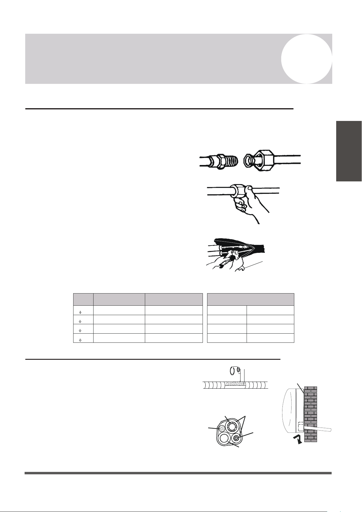
Connecting the Refrigerant Piping to the Indoor Unit
Wrapping the Lines and Mounting the Indoor Unit
Once the copper piping kit coil is unwound,
refer to the below instructions to proceed:
1. Bring the ends of both the copper line and
the indoor unit line together. Align the
centers of the pipes that will be connected.
2. Remove the indoor unit piping cap, and
check that no debris is inside. Some gas
may be heard escaping, it is just nitrogen.
3. Use any leak guard or leak sealant on the
flares of the piping if available. Attach the
flare nut and tighten as much as possible by
hand. Torque correctly to the specifications
found on the next page using two wrenches.
Repeat the process for the other copper line.
For mounting the indoor unit, proceed as follows:
1. Arrange the pipes, cables, and drain hose well.
2. Lag the pipe joints with insulation material, and
secure with vinyl tape as depicted in the figure.
3. Run the bound bundle through the wall hole,
and mount the indoor unit securely onto the
mounting plate. Press/push the lower part of the
indoor unit so it clicks onto the mounting plate.
Torque Wrench
Page 29
6
Indoor Unit Installation Instructions
Indoor Unit
Installation
TIGHTENING TORQUE FOR PROTECTION CAPS AND FLANGE CONNECTION
PIPE
1/4”
( 6.35)
3/8”
( 9.52)
1/2”
( 12.7)
5/8”
( 16)
TIGHTENING TORQUE
TIGHTENING TORQUE
[N x m]
[N x m]
CORRESPONDING STRESS
(using a 20 cm wrench)
15 - 20
31 - 35
35 - 45
75 - 80
Service Port Nut
Protection Caps
7 - 9
25 - 30
Wrist Strength
Arm Strength
Arm Strength
Arm Strength
Refrigerant
Pipe
Refrigerant
Pipe
Insulation
Sleeve
Connection
Cable
Condensed Water
Drain Pipe
Covered by Vinyl Tape
Mounting Plate
Outdoor Unit Installation Location Selection
Follow the below best practices for selecting an optimal space for installation the indoor unit:
• DO NOT install the unit near sources of heat, steam, or flammable gases.
• DO NOT install the system in areas prone to extreme winds or dust.
• DO NOT install the outdoor unit in an area that has many passersby.
• DO select a location where the air discharge and operating sound level will not disturb
others.
• DO install the system in a shaded area or utilize a cover/sun protection that will not
interfere with air flow. This will also protect the system from rain or snow.
• DO install the unit in a safe and sturdy location.
• DO install rubber vibration absorbers if the system will be subject to vibrations.
• DO obey the following tolerances depicted in the illustration below to ensure air flow:
Page 30
7
Outdoor Unit Installation Instructions
Outdoor Unit
Installation
Minimum Required Installation Space
20”
500mm
20”
500mm
12”
300mm
12”
300mm
79”
2000mm
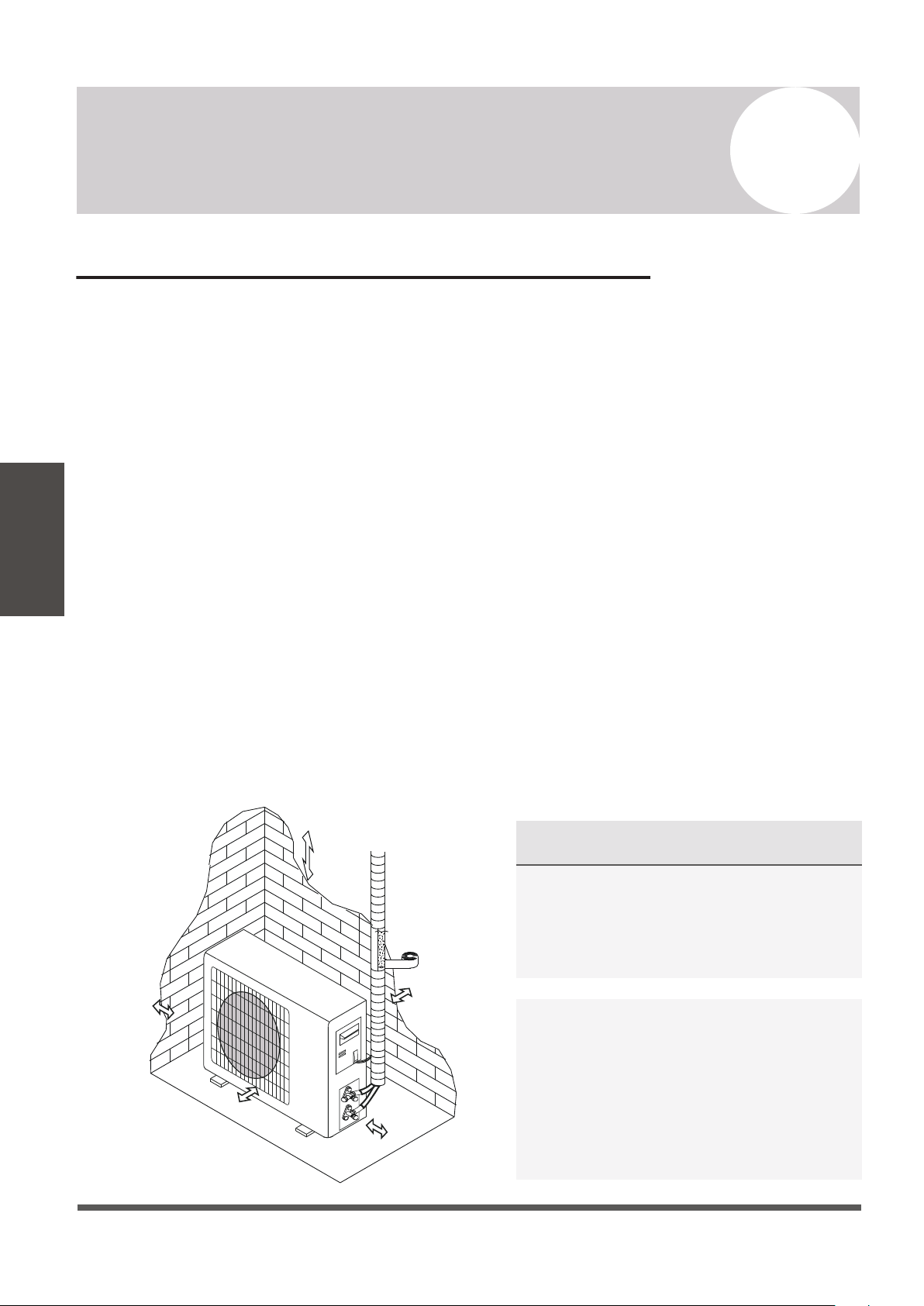
SPECIAL CONSIDERATIONS FOR EXTREME
WEATHER CONDITIONS
If the unit is exposed to heavy wind:
Install unit so that air outlet fan is at a
90° angle to the direction of the wind.
If needed, build a barrier in front of the
unit to protect it from extremely heavy winds.
If the unit is frequently exposed to heavy rain or
snow: Build a shelter above the unit to protect it
from the rain or snow. Be careful not to obstruct
air flow around the unit. If the unit is frequently
exposed to salty air (seaside air): Use specifically
approved anti-corrosion coating sprays onto the
heat exchanger surface in order to resist corrosion.
Mounting the Outdoor Unit to the Selected Location
The outdoor unit should be installed either on a pad or on a solid wall and fastened securely.
Follow the procedure below before connecting any pipes or cables:
• Decide what the best position on the wall or on the ground is, and leave enough space to be
able to carry out maintenance easily. Anchoring dimensions are provided on Page 42.
• If wall mounting, fasten the support brackets to the wall using hardware that is particularly
suited for the type of wall. Use the appropriate amount of hardware for the application.
• The unit must be installed following all national regulations.
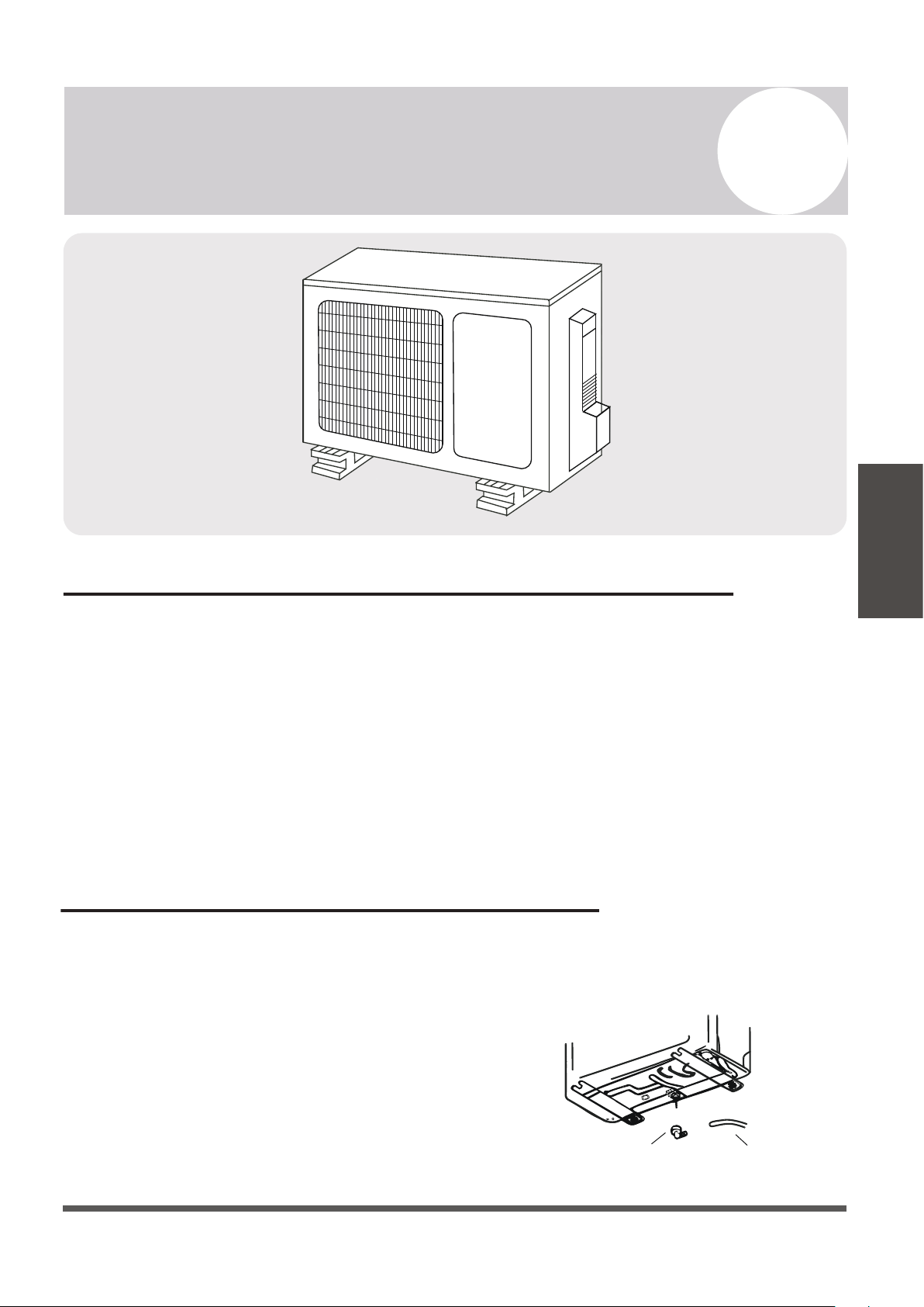
Outdoor Unit Condensate Water Drainage
The condensate water and the ice formed in the outdoor unit during heat mode can be
directed away using the optional drain pipe included with the system.
1. Fasten the drain port in the 1 inch port located
in the part of the unit depicted in the diagram.
2. Connect the drain port and the drain pipe.
3. Ensure the condensate will drain to a suitable place.
Page 31
7
Outdoor Unit Installation Instructions
Outdoor Unit
Installation
Drain Pipe
Drain Port
Page 32
7
Outdoor Unit Installation Instructions
Outdoor Unit
Installation
BEFORE PERFORMING
ANY ELECTRICAL WORK,
READ THESE REGULATIONS
1.
All wiring must comply with local and
national electrical codes, and must be
installed by a fully-licensed electrician.
2.
All electrical connections must be made
according to the Electrical Connection
Diagram located on the side panels of the
indoor and outdoor units.
3.
If there is a serious safety issue with the
power supply, stop work immediately.
Explain your reasoning to the client, and
suspend all installation of the unit until the
safety issue is properly resolved.
4.
Power voltage should be within 90-110% of
rated voltage. Insufficient power supply can
cause electrical shock or fire.
5.
Connect power through fixed wiring, install a
surge protector, and disconnect switch box.
Use a dedicated circuit breaker with a capacity
of 1.5 times the maximum current of the unit.
6.
A properly rated HACR-type fuse or circuit
breaker that disconnects all poles and has a
contact separation of at least 1/8in (3mm)
must be incorporated in the fixed wiring.
The qualified technician must use an
approved circuit breaker or switch.
7.
Only connect the unit to a dedicated individual
branch circuit breaker. Do not connect
another appliance to that same circuit.
8.
Be sure to properly ground the air conditioner.
9.
Every wire must be firmly connected. Loose
wiring can cause the terminal to overheat,
resulting in product malfunction and possible
fire.
10. Do not
let wires touch or rest against
refrigerant tubing, the compressor, or
any other moving parts within the unit.
WARNING
1. Prepare the cable for connection:
USE THE RIGHT CABLE
•
Outdoor Power Cable: H07RN-F
•
Signal Cable: H07RN-F
Minimum Cross-Sectional Area of
Power and Signal Cables
BEFORE PERFORMING ANY ELECTRICAL
OR WIRING WORK, TURN OFF THE MAIN
POWER TO THE SYSTEM.
North America
Appliance Amps (A)
AWG
10 18
13 16
15 14
20 12
30 10
Using wire strippers, strip the rubber jacket from
both ends of cable to reveal about 40mm (1.5 in)
of the wires inside. Strip the insulation from the
ends of the wires. Using a wire crimper, crimp
u-lugs on the ends of the wires. Note that some
cables come with preinstalled u-lugs from factory.
INDOOR UNIT TERMINAL POSITION #1 connects
to OUTDOOR UNIT TERMINAL POSITION #1.
INDOOR UNIT TERMINAL POSITION #2 connects
to OUTDOOR UNIT TERMINAL POSITION #2.
INDOOR UNIT TERMINAL POSITION #3 connects
to OUTDOOR UNIT TERMINAL POSITION #3.
INDOOR UNIT TERMINAL POSITION “GROUND”
connects to OUTDOOR UNIT GROUNDING LUG
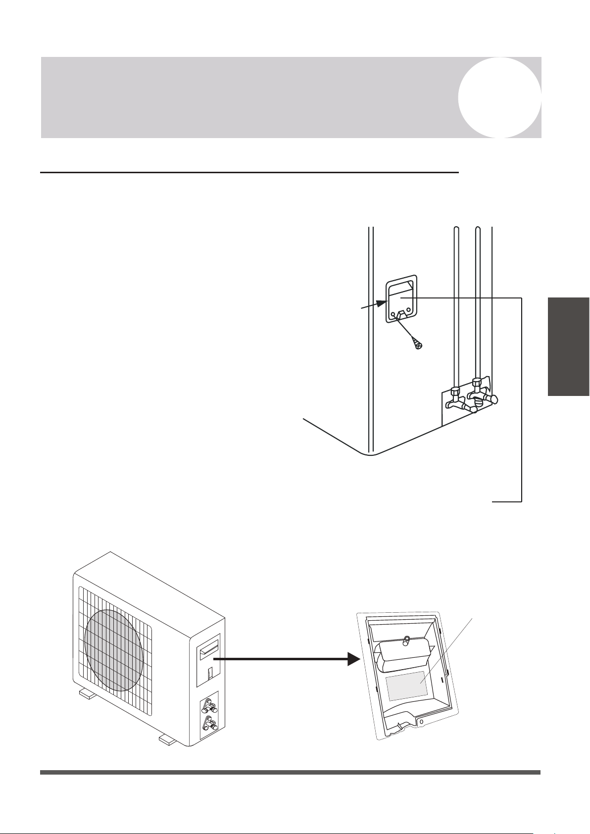
Power/Signal Electrical Wiring to the Outdoor Unit
On the outdoor unit, the wiring diagram is located in the inner side of the handle cover.
The outside unit’s terminal block is protected
by an electrical wiring cover on the side of
the unit. A comprehensive wiring diagram is
printed on the inside of the wiring cover.
1. Unscrew and remove the handle on the
right side plate of the outdoor unit.
2. Wire the system using the appropriate
gauge wire found on page 29/32 and the
wiring diagram found on the handle
cover. See page 43 for more details.
3. Fasten the power connection wires into
place using the supplied wire clamps.
4. Check the wiring against the diagram to
ensure it is wired correctly. A proper
ground must be established.
5. Rescrew and reinstall the cover handle.
Cover
Outdoor Unit Wiring Diagram
is located on the inside of the
wire cover on the outdoor unit.
Outdoor Handle Cover
Wiring Diagram
Page 33
7
Outdoor Unit Installation Instructions
Outdoor Unit
Installation
Connection of the Refrigerant Piping
The length of refrigerant piping will affect the performance and energy efficiency of the unit.
Nominal efficiency is tested on units with a pipe length of 5 meters (16 ft).
Refer to the table below for specifications on the maximum length and drop height of piping.
Page 34
7
Outdoor Unit Installation Instructions
Outdoor Unit
Installation
Pioneer WYT Series Mini Split
22 SEER series MODEL/Capacity (Btu/h)
9K 12K 18K
Liquid Pipe Diameter
24K
Gas Pipe Diameter
Length of Pipe with Standard Charge
Maximum Distance Between Indoor and Outdoor Unit
Max. Difference in Level Between Indoor and Outdoor Unit
Type of Refrigerant
1/4”
( 6.35)
1/4”
( 6.35)
3/8”
( 9.52)
3/8”
( 9.52)
1/4”
( 6.35)
1/2”
( 12.7)
7.5m / 25ft
15m / 49ft
20g/m
10m / 33ft
Additional Refrigerant Charge (For each add’l foot after 16 ft.)
R410A R410A
R410A
5/8”
( 15.88)
R410A
1/4”
( 6.35)
0.22oz/ft
7.5m / 25ft
15m / 49ft
20g/m
10m / 33ft
0.22oz/ft
7.5m / 25ft
20m / 65ft
20g/m
15m / 49ft
0.22oz/ft
7.5m / 25ft
20m / 65ft
20g/m
15m / 49ft
0.22oz/ft
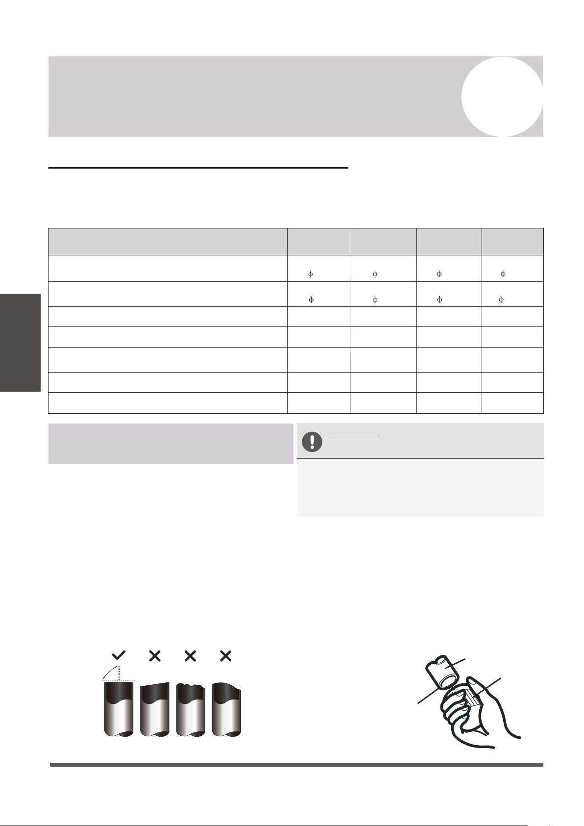
Connection Instructions –
Refrigerant Piping
Step 1: Cut pipes
When preparing refrigerant pipes, take extra care
to cut and flare them properly. This will ensure
efficient operation and minimize the need for
future maintenance.
1. Measure the distance between the indoor and
outdoor units.
2. Using a pipe cutter, cut the pipe a little
longer than the measured distance.
3. Make sure that the pipe is cut at a perfect 90°
angle. Refer below for bad cut examples:
Oblique Rough Warped
90°
DO NOT DEFORM PIPE
WHILE CUTTING
Be extra careful not to damage, kink, or
deform the pipe while cutting. This will
drastically reduce the efficiency and capacity
of the unit and may cause internal damage.
Step 2: Remove any burrs carefully.
Burrs can affect the air-tight seal of refrigerant
piping connection. They must be completely
removed. Follow these steps for proper deburring:
1.
Hold the pipe at a downward angle to
prevent burrs from falling into the pipe.
2.
Using a reamer or deburring tool, remove
all burrs from the cut section of the pipe.
Pipe
Reamer
Point down
Ensures no shavings
can fall inside of tubes
Page 35
7
Outdoor Unit Installation Instructions
Outdoor Unit
Installation
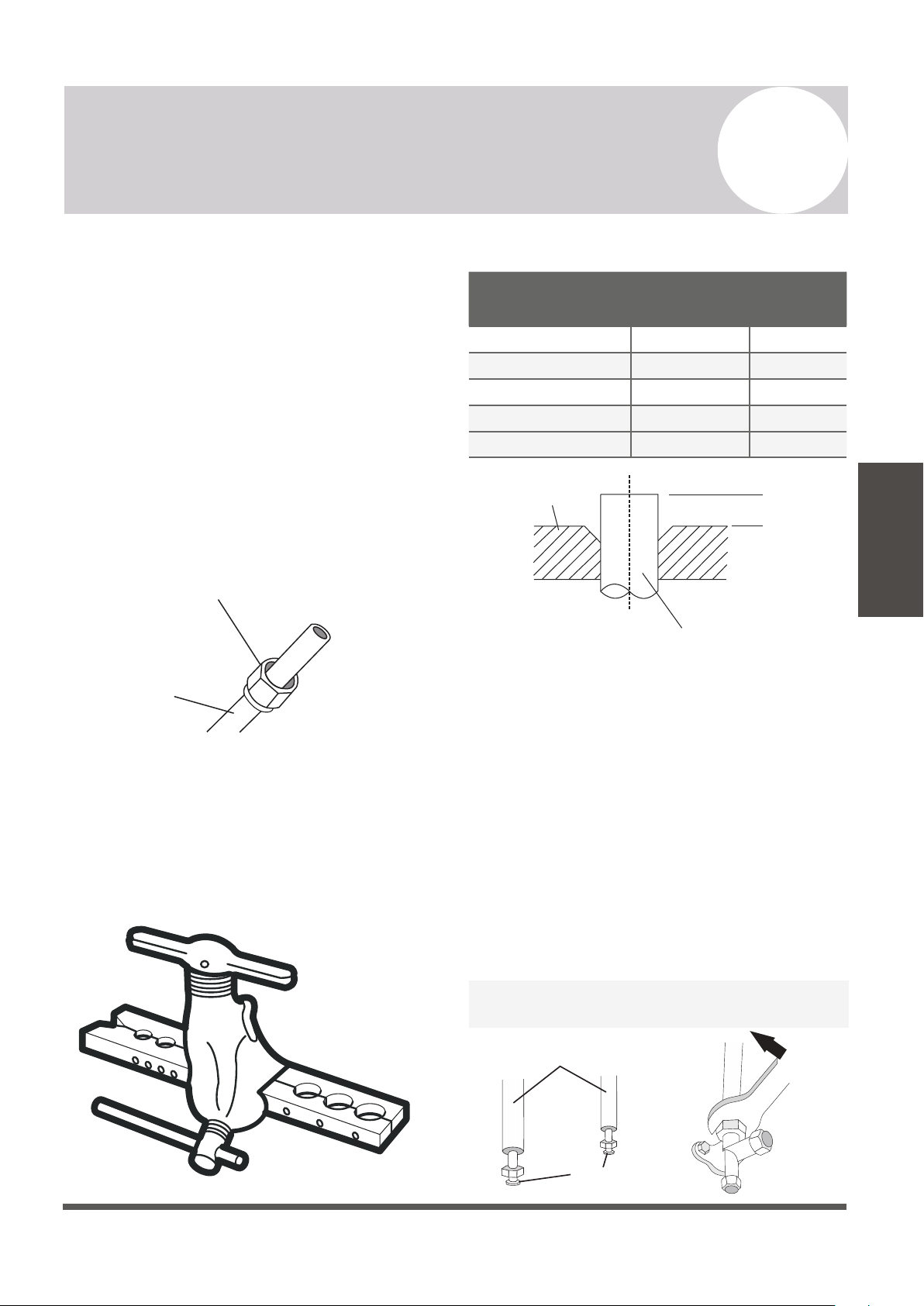
Step 3: Flare pipe ends
Proper flaring is essential to achieve an airtight
seal.
1.
After removing burrs from cut pipe, seal
the ends with PVC tape to prevent foreign
materials from entering the pipe.
2.
Sheath the pipe with insulating material.
3.
Place flare nuts on both ends of pipe. Make
sure they are facing the correct direction,
because they cannot be put on or have
their direction chaged after flaring.
Flare Nut
Copper Pipe
4.
Remove PVC tape from ends of pipe when
ready to perform flaring work.
5.
Clamp flare form on the end of the pipe.
The end of the pipe must extend beyond the
edge of the flare form in accordance with the
dimensions shown in the following table:
PIPING EXTENSION BEYOND FLARE FORM
Outer Diameter of
Pipe (mm)
A (mm)
Min. Max.
Ø 6.35 (Ø 1/4”) 0.7 (0.03”) 1.3 (0.05”)
Ø 9.52 (
Ø 3/8”)
1.0 (0.04”) 1.6 (0.06”)
Ø 12.7 (Ø 1/2”) 1.0 (0.04”) 1.8 (0.07”)
Ø 16 (Ø 5/8”)
Ø 19 (Ø 3/4”)
2.0 (0.08”) 2.2 (0.09”)
2.0 (0.08”) 2.4 (0.1”)
Flare Form
Pipe
A
6.
Place flaring tool onto the form.
7.
Turn the handle of the flaring tool
clockwise until the pipe is fully flared.
8.
Remove the flaring tool and flare form, then
inspect the end of the pipe for cracks and
successful, even flaring.
Step 4: Connect pipes
When connecting refrigerant pipes, be careful
not to use excessive torque, or to deform the
piping in any way. One should first connect the
low-pressure pipe, then the high-pressure pipe.
If provided by the supplier, apply leak
guard material on all flared mating surfaces.
Connection Pipes
Flare Nuts
Page 36
7
Outdoor Unit Installation Instructions
Outdoor Unit
Installation
MINIMUM BEND RADIUS
When bending connective refrigerant piping,
the minimum bending radius is 10 cm (4”).
Radius ≥10cm (4 in)
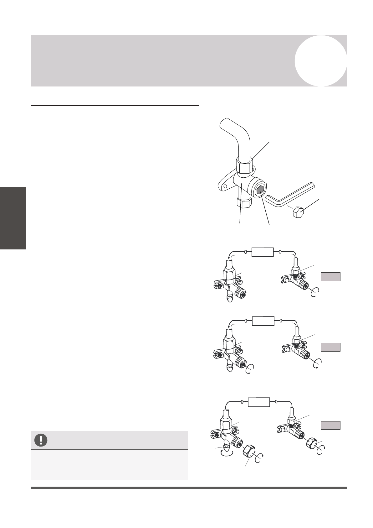
Instructions for Connecting Piping
to Outdoor Unit
1.
Unscrew the cover from the packed valve on
the side of the outdoor unit.
Valve Cover
2.
Remove protective caps from the valve ends.
3.
Align flared pipe end with each valve, and
tighten the flare nut as tightly as possible
by hand.
4.
Using a spanner, grab the body of the valve.
Do not grab the nut that seals the service
valve.
USE SPANNER TO GRAB THE
BODY OF THE SERVICE VALVE
Torque from tightening the flare nut can snap
off other parts of valve.
5.
While firmly gripping the body of the valve,
use a torque wrench to tighten the flare
nut according to the correct torque values.
6.
Loosen the flaring nut slightly, then tighten
again.
7.
Repeat Steps 3 to 6 for the remaining pipe.
DO NOT USE EXCESSIVE TORQUE
Excessive force can break the nut or damage
the refrigerant piping. You must not exceed
the torque requirements shown in the table
provided on page 29.
Gas Tap
Liquid Tap
Indoor Unit
Protection Caps
Liquid Valve
Gas Valve
Service Port Nut
Tap
Air Evacuation and Bleeding the Circuit
The air and/or humidity left inside the refrigeration circuit can contaminate the refrigerant
and cause abnormal spikes in pressure, leading to eventual compressor malfunction.
Therefore, after having connected the indoor and outdoor units to create a closed system, it is
necessary to bleed the air and humidity out of the circuit through the use of a vacuum pump.
Evacuation should be performed upon initial installation or when the unit is relocated.
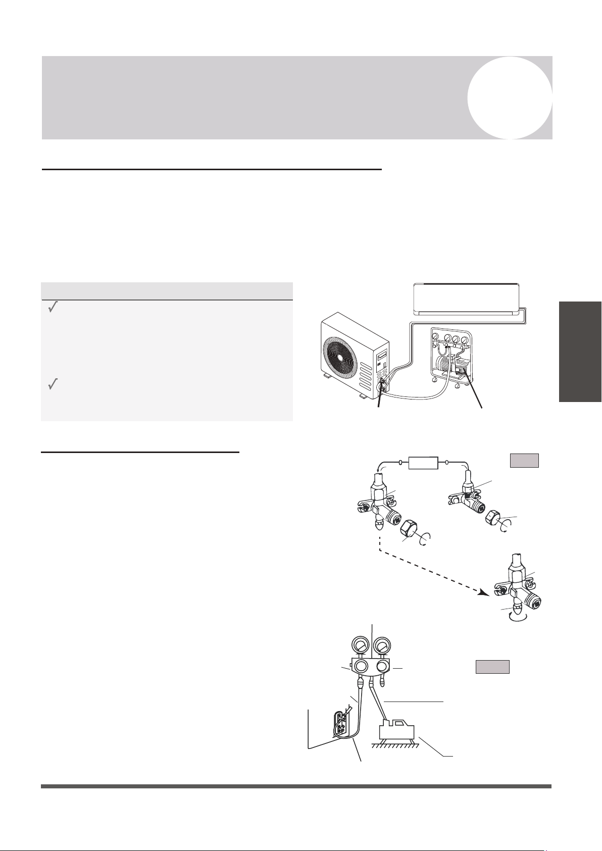
Evacuation Instructions
Before using a vacuum pump and manifold gauge,
read their operation manuals to become familiarized
with using them properly.
1) Unscrew and remove the caps from the
2-way and 3-way valves.
2) Unscrew and remove the cap from the
service port.
3)
Connect the blue (low) hose of the
manifold gauge to service port on the
outdoor unit’s 3-way valve (use an
adapter if needed). Ensure that the pin
fully engages the schrader valve.
4) Connect the yellow (middle) hose from the
manifold gauge to the vacuum pump.
5)
Open the low pressure valve of the manifold
gauge. Keep the high pressure valve closed.
Page 37
7
Outdoor Unit Installation Instructions
Outdoor Unit
Installation
Vacuum PumpService Port
BEFORE PERFORMING EVACUATION
Check to make sure that both high-pressure
and low-pressure pipes between the indoor
and outdoor units are connected properly
in accordance with the “Refrigerant Piping
Connection” section of this manual.
Check to make sure all wiring is connected
properly.
High Pressure
Valve
Service
Port Nut
3-Way
Valve
2-way
Valve
3-way Valve
Refrigerant Flow Direction
Indoor Unit
Valve Cap
Valve Cap
Yellow (middle) hose
Vacuum Pump
3-Way Valve
Blue (low) hose
Low Pressure
Valve
Low Pressure Gauge High Pressure Gauge
Manifold Gauge
[2] Turn
[1] Turn
[1] Turn
Step 2
Step 3-5
Step 1
Evacuation Instructions (Cont’d)
6.
Turn on the vacuum pump to evacuate the system.
7.
Run the vacuum for at least 15 minutes, or until the
Compound Meter reads -76cmHG (-100 kPa or -30
inHg).
8.
Close the low pressure side of the manifold gauge,
and turn off the vacuum pump.
9.
Wait for 5 minutes, then verify that there has been
no rise in the vacuum reading.
10.
If there is a rise in the system vacuum, refer to “Gas
Leak Check” section for information on how to check
for leaks. If no change in vacuum reading, unscrew
the cap from the service valve (high pressure valve).
11.
Insert a hexagonal wrench into the service valve (2-way
valve) and open the valve by turning the wrench in a
1/4 counterclockwise turn. Wait and listen for gas to
exit the system, then close the valve after 5 seconds.
12.
Watch the pressure gauge for a few minutes to make
sure that there is no drop in pressure. The Pressure
Gauge should now show higher than the
atmospheric pressure.
13.
Remove the charge hose from the service port.
14.
Using a hexagonal wrench, fully open both the high
pressure and low pressure valves.
15.
Tighten valve caps on all three valves (service port,
high pressure, low pressure) by hand. Tighten further
using a torque wrench if needed.
Service
Port Nut
Page 38
7
Outdoor Unit Installation Instructions
Outdoor Unit
Installation
OPEN VALVE STEMS GENTLY
When opening valve stems, turn the hexagonal
wrench until it comes into contact with stopper.
Do not try to force the valve to open further.
Flare Nut
Cap
Valve Body
Valve Stem
2-Way Valve
3-Way Valve
2-Way Valve
2-Way Valve
Valve Cap
Valve Cap
3-Way Valve
3-Way Valve
[11] Open 1/4 Turn
[15] Tighten
[15] Tighten
[15] Tighten
[14] Turn to Fully
Open Valve
[14] Turn to Fully
Open Valve
Indoor Unit
Step 11
Step 14
Step 15
Indoor Unit
Indoor Unit
Page 39
8
Electrical/Gas Leak Check and Test Run
Electrical/Gas
Leak Check
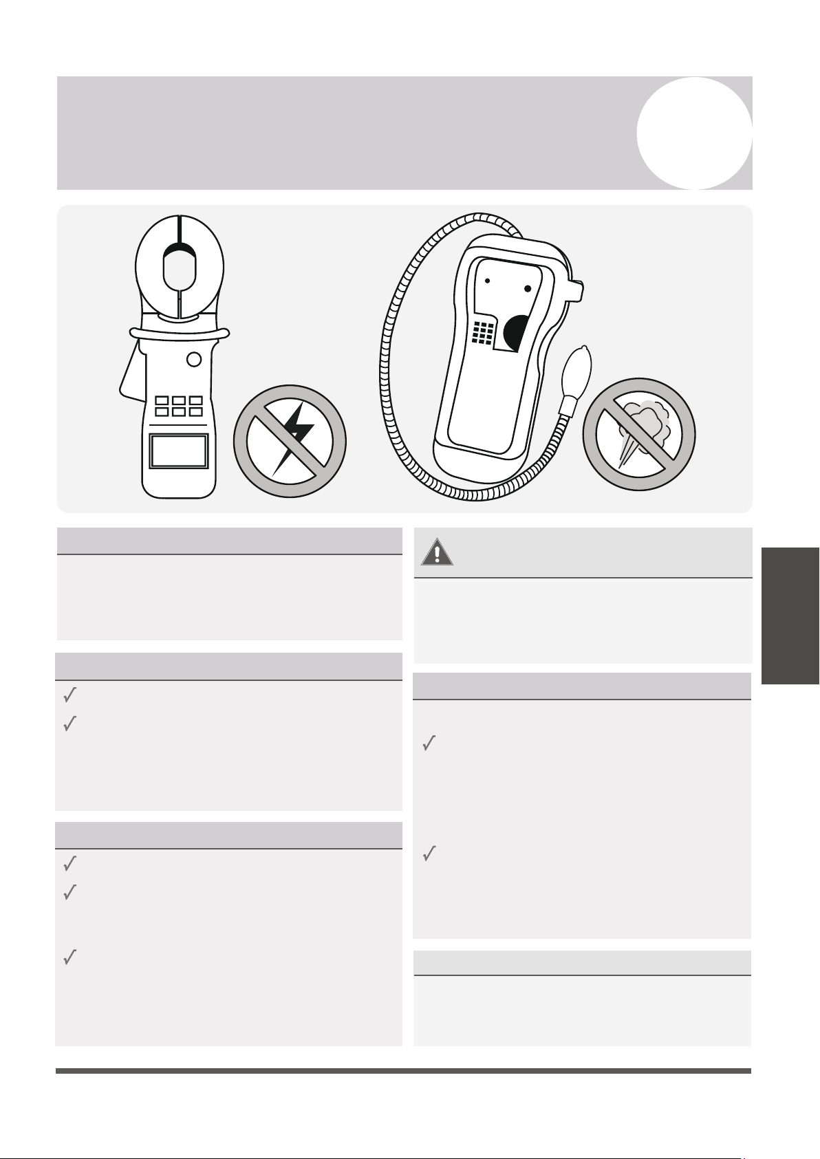
ELECTRICAL SAFETY CHECKS
After installation, confirm that all electrical wiring
is installed in accordance with local and national
regulations, and according to the Installation
Manual.
BEFORE TEST RUN
Check Grounding Work
Measure grounding resistance by visual
detection or with a grounding resistance tester.
Grounding resistance must be less than 4Ω.
Note: This may not be required in some locations.
DURING TEST RUN
Check for Electrical Leakage
During the Test Run, use an electroprobe and
and multi-meter to perform a comprehensive
electrical leakage test.
If electrical leakage is detected, turn off the
unit immediately and call a licensed electrician
to find and resolve the cause of the leakage.
Note: This may not be required in some locations.
GAS LEAK CHECKS
There are 2 methods to check for gas leakage:
Soap and Water Method
Leak Detector Method
WARNING – RISK OF
ELECTRIC SHOCK
ALL WIRING MUST COMPLY WITH
LOCAL AND NATIONAL ELECTRICAL
CODES, AND MUST BE INSTALLED BY
A LICENSED ELECTRICIAN.
Using a soft brush, apply soapy water or
liquid detergent to all pipe connection
points on the indoor unit and outdoor unit.
The presence of bubbles indicates a leak.
If using leak detector, refer to the device’s
operation manual for proper usage
instructions.
AFTER PERFORMING GAS LEAK CHECKS
After confirming that the all pipe connection
points DO NOT leak, replace the valve cover
on the outside unit.

Test Run
PASS/FAIL?
Page 40
8
Electrical/Gas Leak Check and Test Run
Test Run
BEFORE TEST RUN
Only perform a test run after the following
steps have been completed:
Electrical Safety Checks
Gas Leak Checks
No Electrical Leaks or Abnormal Noises
Unit is Properly Grounded
All Electrical Terminals Properly Covered
Indoor and Outdoor Units Securely Installed
All Pipe Connections Points Do Not Leak
Water Drains From Drain Hose Properly
All Piping is Properly Insulated
Indoor Unit Responds to Remote Controller
Indoor Unit Louvers Work Properly
System Works in Both HEAT + COOL mode
Confirm that the unit’s electrical system is
safe and is operating properly.
Check all flare nut connections and confirm
that the system is not leaking.
Opened Valves
Confirm that both the gas and liquid
valves (high/low) are 100% fully opened.
TEST RUN INSTRUCTIONS
The following test run should be performed
for 30 minutes:
AFTER TEST RUN COMPLETION
After the 10 boxes above have been checked as having PASSED, perform the following operation:
1. Using the remote control, return the system to a normal desired operating temperature.
2. Using insulation tape, wrap the indoor unit refrigerant pipe connections that were left uncovered
during the indoor unit installation process.
IF AMBIENT TEMPERATURES ARE TOO LOW TO RUN A COOLING TEST:
If outside temperatures are too low to permit COOLING mode on the remote, do the following:
1. Turn the unit on using the emergency button as depicted on Page 8.
2. Run the cooling mode test as normal, and turn the unit back off using the button when complete.
DOUBLE CHECK ALL PIPE CONNECTIONS
During operation, the pressure of the refrigerant circuit will increase. This may reveal leaks that
were not present during your initial leak check. Take time during the Test Run to double-check
that all copper pipe connection points are leak-free. Refer to the Leak Check page for instructions.
Cooling mode pressures should be 120-155 PSI. Heating mode pressures should be 320-440 PSI.
1. Connect power to the unit.
2.
Press the ON/OFF button on the remote
controller to turn it on.
4.
Let each function run for 5 minutes, and
perform the following checks:
3. Press the MODE button to scroll through
the following functions, one at a time:
• COOL – Select lowest possible temperature
• HEAT – Select highest possible temperature
Page 41
9
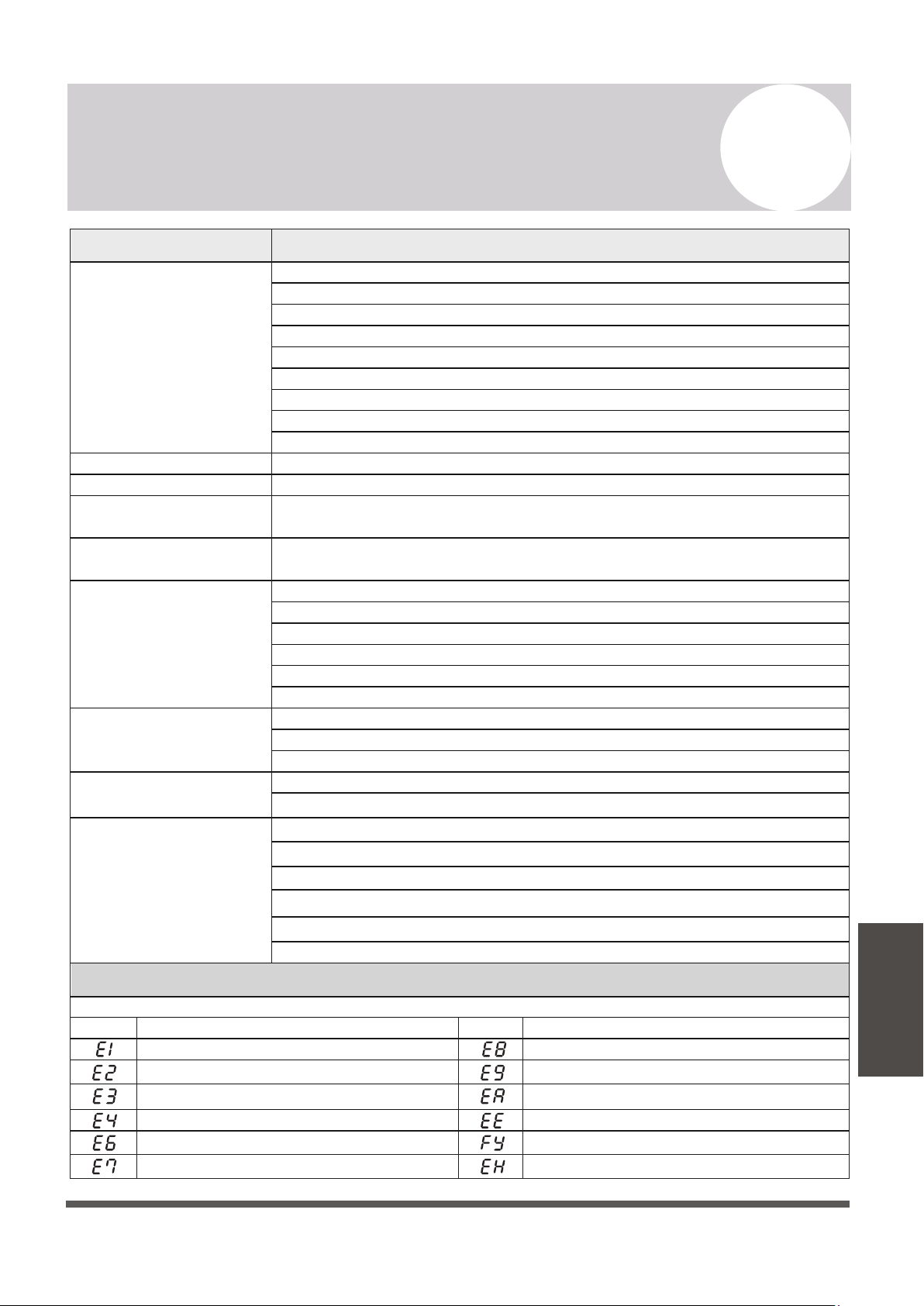
Troubleshooting
Troubleshooting
MALFUNCTION
If there are strange odors...
If there’s running water...
If the airflow is
insufficient, and the
air is not hot or cold
enough...
If the display is off...
If a fine mist is coming
from the air outlet...
If the appliance does not
respond to commands...
If the appliance
does not operate
or respond...
Switch off the air
conditioner immediately
and cut off the power
supply in the event of...
ERROR SIGNALS ON THE DISPLAY
POSSIBLE CAUSES
There is a power failure/plug pulled out
The indoor/outdoor unit fan motor was damaged
There is a faulty compressor or thermomagnetic circuit breaker
There is a faulty protective device or fuses
The electrical connections are loose
The system has entered a protection mode
The TIMER-ON function is active
The system has entered an overvoltage or undervoltage protection
The air filter is dirty
The electronic control board was damaged
There was a backflow of liquid into the refrigerant circulation.
This occurs when the air in the room becomes very cold, for example in
“COOLING” or “DEHUMIDIFICATION/DRY” modes
The temperature setting is unsuitable
The air conditioner intakes and outlets may be obstructed
This noise is made by the expansion or contraction of the front panel due
to variations in temperature, and if so, is normal
The fan speed may be set at the minimum
The air filter may be dirty
The system may be getting low on refrigerant, pressures should be checked
There may be too many other heat sources in the room
The remote control may not be close enough to the indoor unit
The batteries of remote control may need to be replaced
There are obstacles between remote control and indoor unit signal receiver
The DISPLAY button has been pressed
Strange noises not due to expansion/contraction are heard during operation
There has been a power failure
The electronic control board is faulty or malfunctioning
Any fuses or switches are faulty or malfunctioning
The sound of spraying water or objects are heard inside the appliance
The cables or plugs have overheated
There are very strong odors being emitted from the appliance
If strange noises are
being emitted...
Indoor temperature sensor fault
Description of the errorDisplay
Outdoor pipe temperature sensor fault
Indoor pipe temperature sensor fault
Malfunction of indoor fan motor
Refrigerant system leakage or fault
Outdoor air temperature sensor fault
Outdoor discharge temperature sensor fault
Outdoor IPM module fault
Display
Description of the trouble
Outdoor PCB EEPROM fault
Outdoor current detection fault
In case of error, the display on the indoor unit may show the following error codes:
Outdoor suction temperature sensor fault
Refrigerant Leak / Low Pressure Detected
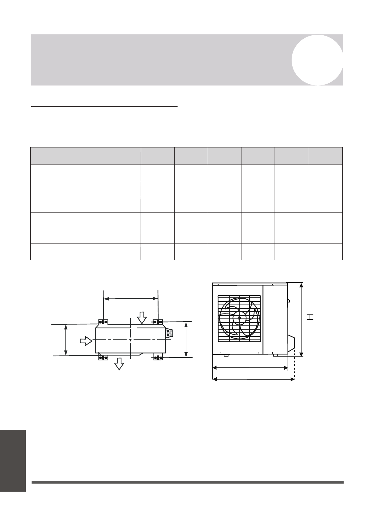
Pioneer WYT Series Mini Split
MODEL/Capacity (Btu/h)
A B D
YN009ALFI22RPD (9,000 BTU - 110/120V)
H
YN012ALFI22RPD (12,000 BTU - 110/120V)
YN009GLFI22RPD (9,000 BTU - 208/230V)
YN012GLFI22RPD (12,000 BTU - 208/230V)
YN024GLFI22RPD (24,000 BTU - 208/230V)
Air Inlet
Air Inlet
Air Outlet
438 mm
17-1/4 in.
438 mm
17-1/4 in.
438 mm
17-1/4 in.
438 mm
17-1/4 in.
586 mm
23-1/16 in.
607 mm
23-7/8 in.
278 mm
10-15/16 in.
278 mm
10-15/16 in.
278 mm
10-15/16 in.
278 mm
10-15/16 in.
347.5 mm
13-11/16 in.
390 mm
15-3/8 in.
254.8 mm
10 in.
254.8 mm
10 in.
254.8 mm
10 in.
254.8 mm
10 in.
312.7 mm
12-5/16 in.
397.2 mm
15-5/8 in.
546 mm
21-1/2 in.
546 mm
21-1/2 in.
546 mm
21-1/2 in.
546 mm
21-1/2 in.
699 mm
27-1/2 in.
804.2 mm
31-11/16 in.
727.6 mm
28-5/8 in.
727.6 mm
28-5/8 in.
727.6 mm
28-5/8 in.
727.6 mm
28-5/8 in.
850 mm
33-7/16 in.
910 mm
35-13/16 in.
810 mm
31-7/8 in.
810 mm
31-7/8 in.
810 mm
31-7/8 in.
810 mm
31-7/8 in.
927 mm
36-1/2 in.
978 mm
38-1/2 in.
YN018GLFI22RPD (18,000 BTU - 208/230V)
W1 W2
Anchoring the Outdoor Unit
The outdoor unit can be anchored to the ground or to wall-mounted brackets. The following
is a list of different outdoor unit sizes and the distance between their mounting feet. Prepare
the installation base of the unit according to the dimensions found below:
Page 42
A
Appendix
Outdoor Unit
Installation
Appendix
If installing the unit on the ground or on a
concrete mounting platform, do the following:
1. Mark the positions for four expansion bolts
based on dimensions in the “Unit Mounting
Dimensions” chart.
2. Pre-drill holes for expansion bolts.
3. Clean concrete dust away from holes.
4. Place a nut on the end of each expansion bolt.
5. Hammer expansion bolts into each hole.
6. Remove the nuts from expansion bolts, and
place the outdoor unit onto the bolts.
7. Put washers onto each expansion bolt, then
replace each of the nuts.
8. Using a wrench, tighten each nut until snug.
WHEN DRILLING INTO CONCRETE,
WEAR EYE PROTECTION AT ALL TIMES!
A
W
B
D
Air inlet
Air outlet
Air inlet
A
B
D
W1
W2
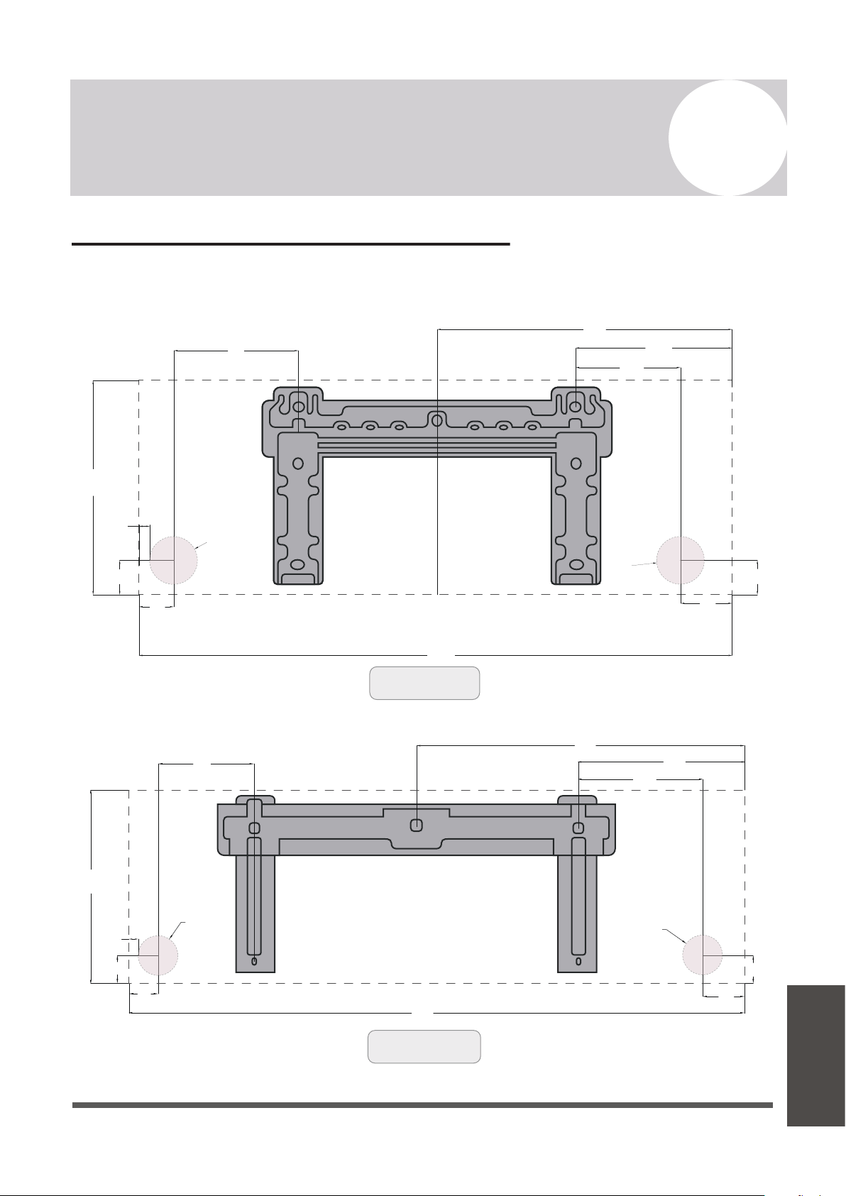
Guidelines for Drilling the Wall Hole
Below are the suggested locations for the wall hole for systems between 9,000 - 24,000 BTU.
Both left side/right side exits are considered. Confirm holes are appropriate by corner tracing.
Page 43
A
Appendix
5
7/8”
1
5/8”
12
1/16”
32
5/16”
1
3/4”
1
5/8”
6
11/16”
9
13/16”
17
1/4”
3
1/8”
Ø
2
1/2”
Ø
2
1/2”
1/2”
Left Side Exit
Left Side Exit
Right Side Exit
Right Side Exit
(For 9K BTU Systems)
All Distances in Inches
1
5/8”
1
3/4”
3
1/8”
17
1/4”
9
13/16”
6
11/16
”
1
5/8”
9
3/4”
12
1/16”
36
1/4”
Ø
2
1/2”
Ø
2
1/2”
1/2”
(For 12K BTU Systems)
All Distances in Inches
Appendix
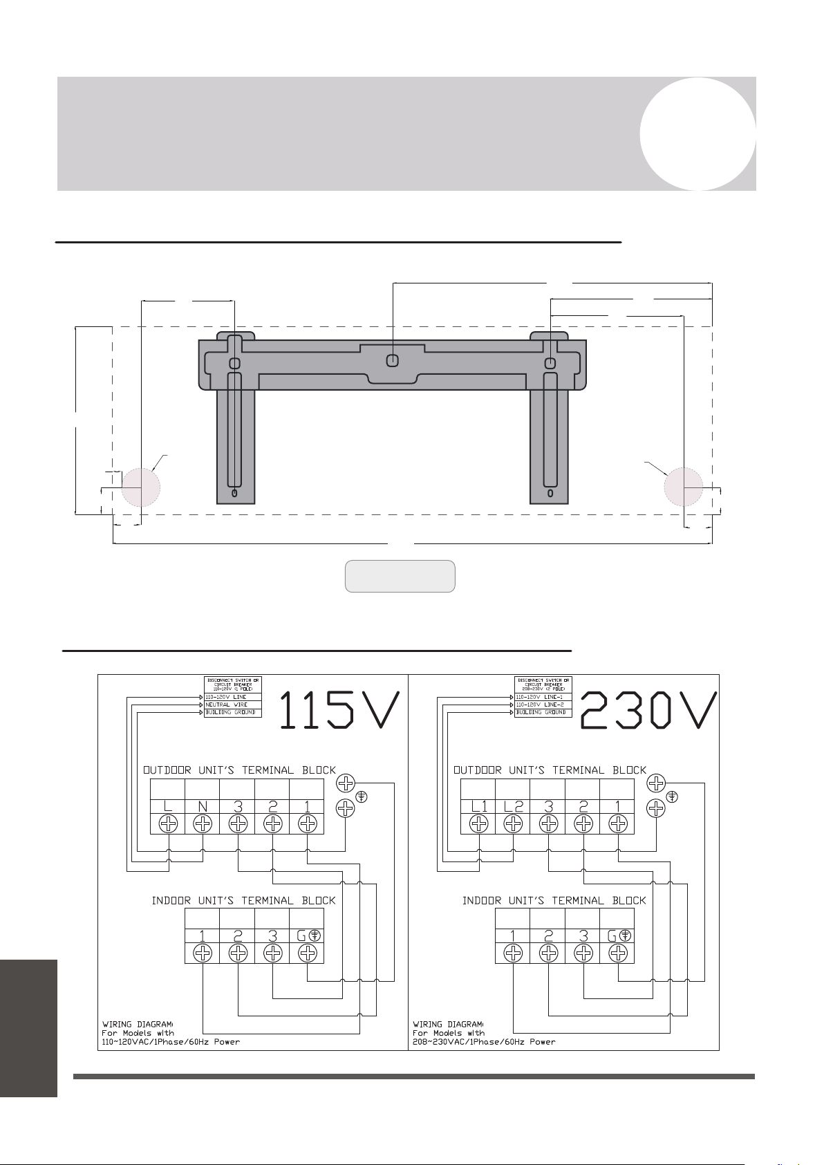
Left Side Exit Right Side Exit
1
5/8”
1
3/4”
2
1/8”
22
3/16”
11
7/8”
9
3/4
”
1
5/8”
8
3/4”
13
”
43
3/16”
Ø
2
1/2”
Ø
2
1/2”
1/2”
(For 18K-24K Systems)
All Distances in Inches
Appendix
Guidelines for Drilling the Wall Hole (continued)
Simplified Wiring Diagram (115V and 230V)
Page 44
A
Appendix
European Disposal Guidelines
This appliance contains refrigerant and other potentially hazardous materials. When disposing of
this appliance, the law requires special collection and treatment. Do not dispose of this product as
household waste or unsorted municipal waste.
When disposing of this appliance, you have the following options:
Page 45
A
Appendix
Appendix
• Dispose of the appliance at a designated municipal electronic waste collection facility.
• When buying a new appliance, the retailer takes back the old appliance free of charge.
• The manufacturer takes back the old appliance free of charge.
• Sell the appliance to certified scrap metal dealers.
Special Notice
Disposing of this appliance improperly, or in other natural surroundings, endangers your health
and is bad for the environment. Hazardous substances may leak into the ground water and enter
the food chain. Please follow proper disposal protocol.

The design and specifications of this product are subject to change without prior notice
as development continues. Consult with the sales agency or manufacturer for details.
Refer to the equipment nameplate for all other applicable specifications.
is a registered trademark of Parker Davis HVAC International, Inc.
Parker Davis HVAC International, Inc.
3250 NW 107 Avenue, Doral, FL 33172 - USA
Tel
: (305) 513-4488
Fax
Scan the below code to visit our support page
where you can find more installation materials:
Copyright 1995-2023, Parker Davis HVAC International, Inc., All rights reserved.
: (305) 513-4499
E-mail
: support@pdhvac.com
Website: https://www.pdhvac.com
Pioneer product line, parts, and supplie
sare
available online for convenient ordering at:
https://www.highseer.com
https://www.pioneerminisplit.com