Loading ...
Loading ...
Loading ...
5. Microphone port (pink). This port connects to a microphone.
6. Line Out port (lime). This port connects to a headphone or speaker. In a 4, 5.1, or
7.1-channel conguration, the function of this port becomes Front Speaker Out.
7. Line In port (light blue). This port connects to a tape, CD, DVD player, or other audio
sources.
Refer to the audio conguration table below for the function of the audio ports in the 2, 4, 5.1,
or 7.1-channel conguration.
Audio 2, 4, 5.1, or 7.1-channel conguration
Port Headset 2-channel 4-channel 5.1-channel 7.1-channel
Light Blue (Rear panel) - Rear Speaker Out Rear Speaker Out Rear Speaker Out
Lime (Rear panel) Front Speaker Out Front Speaker Out Front Speaker Out Front Speaker Out
Pink (Rear panel) - - Center/Subwoofer Center/Subwoofer
Black (Headphone,
Front panel)
- - - Side Speaker Out
8. Power connector. Plug the power cord to this connector.
RATING: • 115Vac/230Vac, 8A/4A, 50Hz/60Hz (WW, TW)
• 220Vac, 4A, 50Hz (Chinese Mainland)
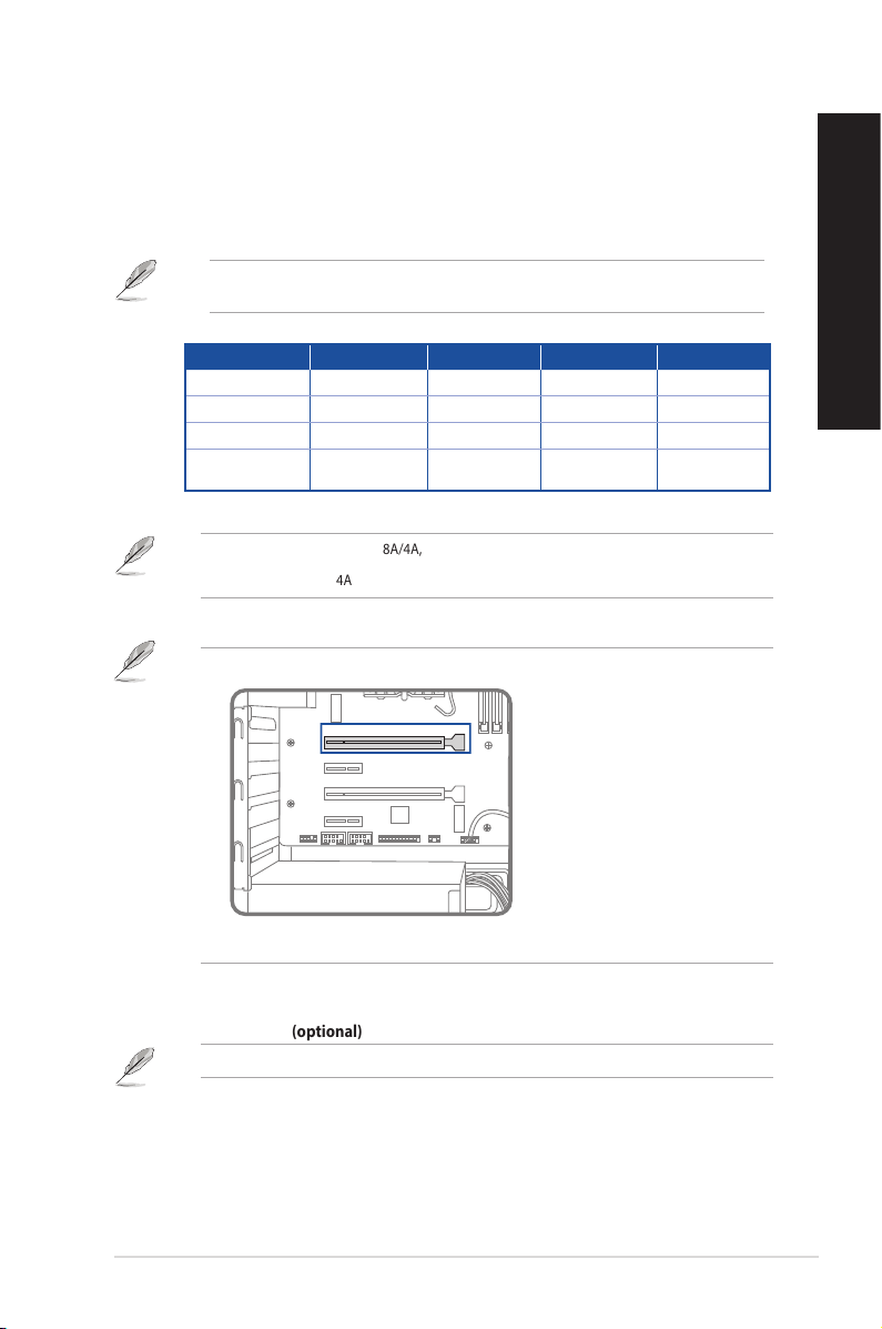
9. Expansion slot brackets. Remove these expansion slot brackets when installing expansion
cards.
• While installing the rst VGA card, please install it in PCIEX16 slot.
PCIEX16
PCIEX1_1
PCIEX16_2
PCIEX1_2
• Refer to Installing a graphics card in your computer for detailed instructions.
10. ASUS Graphics Cards (on selected models only). The display output ports on these
optional ASUS Graphics Cards may vary with dierent models.
11. Intel® Wi-Fi 6 ports (optional). These ports connect to Wi-Fi antennas.
Refer to the section Wi-Fi antennas installation in Chapter 4 for details.
ASUS Desktop PC 19
ENGLISH
ENGLISH
Loading ...
Loading ...
Loading ...