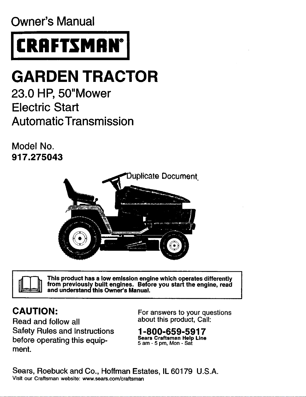
Owner's Manual
ICRIIFTSMIIN°J
GARDEN TRACTOR
23.0 HP, 50"Mower
Electric Start
AutomaticTransmission
Model No.
917.275043
Document
J _ This product has a low em.lssion engine which operates differently I
I
from previously bu,lt engines. Before you start the engine, read
I
and understand this Owner's Manual.
CAUTION:
Read and follow all
Safety Rules and Instructions
before operating this equip-
ment.
For answers to your questions
about this product, Call:
1-800-659-5917
Sears Craftsman Help Line
5 am - 5 pm, Mon- Sat
Sears, Roebuck and Co., Hoffman Estates, IL 60179 U.S.A.
Visit our Craftsman website: www.sears.com/craftsman
Warranty ............................................... 2
Safety Rules ......................................... 3
Product Specifications .......................... 6
Assembly/Pre-Operation ...................... 8
Operation ............................................ 12
Maintenance Schedule ...................... 19
Maintenance ....................................... 19
Service and Adjustments .................... 23
Storage ............................................... 31
Troubleshooting ................................. 32
Repair Parts. ....................................... 36
Sears Service ...................... Back Cover
LIMITED TWO YEAR WARRANTY ON CRAFTSMAN RIDING EQUIPMENT PARTS
For two (2) years from the date of purchase, if this Craftsman Riding Equipment is
maintained, lubricated and tuned up according to the instructions in the owner's
manual, Sears will repair or replace, free of charge, any parts found to be defective in
material or workmanship. Warranty service is available free of charge by returning your
Craftsman riding equipment to your nearest Sears Service Center. In-home warranty
service is available but a trip charge will apply. This warranty applies only while this
product is in the United States.
This Warranty does not cover:
• Expendable items which become worn during normal use, such as blades, spark
plugs, air cleaners, belts and oil filters.
• Tire replacement or repair caused by punctures from outside objects, such as nails,
thorns, stumps, or glass.
• Repairs necessary because of operator abuse, including but not limited to, damage
caused by towing objects beyond the capability of the dding equipment, impacting
objects that bend the frame or crankshaft, or over speeding the engine.
• Repairs necessary because of operator negligence, including but not limited to,
electrical and mechanical damage caused by improper storage, failure to use the
proper grade and amount of engine oil, failure to keep the deck clear of flammable
debris, or the failure to maintain the equipment according to the instructions con-
tained in the owner's manual.
• Engine (fuel system) cleaning or repairs caused by fuel determined to be contami-
nated or oxidized (stale). In general, fuel should be used within thirty (30) days of its
purchase date.
• Riding equipment used for commercial or rental purposes. A product is =used for
commercial purpose" if is used for any purpose other than single family household
dwellings or in usage where profit is made.
LIMITED 90 DAY WARRANTY ON BATTERY
For ninety (90) days from date of purchase, if any battery included with this riding
equipment proves defective in material or workmanship and our testing determines the
battery will not hold a charge, Sears will replace the battery at no charge. Warranty
service is available free of charge by returning your Craftsman riding equipment to
your nearest Sears Service Center. In-home warranty service is available but a trip
charge will apply. This warranty applies only while this product is in the United States.
TO LOCATE THE NEAREST SEARS SERVICE CENTER OR TO SCHEDULE IN-HOME
WARRANTY SERVICE, SIMPLY CONTACT SEARS AT 1-800-4-MY-HOME
This Warranty gives you specific legal rights, and you may also have other rights which
may vary from state to state.
Sears, Roebuck and Co., D/817 WA, Hoffman Estates, IL 60179
2
IMPORTANT: This cutting machine is capable of amputating hands and feet and
throwing, objects. Failure to observe the following safety instructions could result in
serious mlury or death.
Look for this symbol to point out
important safety precautions. It means
CAUTION!!! BECOMEALERT!!I YOUR
SAFETY IS INVOLVED.
CAUTION: In order to prevent
accidental starting when setting up,
transporting, adjusting or making repairs,
always disconnect spark plug wire and
place wire where it cannot contact spark
plug.
_, CAUTION: Do not coast down a hill
in neutral, you may lose control of the
tractor.
CAUTION: Tow only the attachments
that are recommended by and comply
with specifications of the manufacturer of
your tractor. Use common sense when
towing. Operate only at the lowest
possible speed when on a slope. Too
heavy of a load, while on a slope, is
dangerous. Tires can lose traction with
the ground and cause you to lose control
of your tractor.
WARNING: Engine exhaust, some of
its constituents, and certain vehicle
components contain or emit chemicals
known to the State of California to cause
cancer and birth defects or other repro-
ductive harm.
WARNING: Battery posts, terminals
and related accessories contain lead
and lead compounds, chemicals known
to the State of California to cause cancer
and birth defects or other reproductive
harm. Wash hands after handling.
I. GENERAL OPERATION
• Read, understand, and follow all
instructions in the manual and on the
machine before starting.
• Only allow responsible adults, who are
familiar with the instructions, to operate
the machine.
• Clear the area of objects such as rocks,
toys, wire, etc., which could be picked
up and thrown by the blade.
• Be sure the area is clear of other people
before mowing. Stop machine if anyone
enters the area.
• Never carry passengers.
3
• Do not mow in reverse unless absolutely
necessary. Always look down and
behind before and while backing.
• Be aware of the mower discharge
direction and do not point it at anyone.
Do not operate the mower without either
the entire grass catcher or the guard in
place.
• Slow down before tuming.
• Never leave a running machine
unattended. Always turn off blades, set
parking brake, stop engine, and remove
keys before dismounting.
•Tum off blades when not mowing.
• Stop engine before removing grass
catcher or unclogging chute.
• Mow only in daylight or good artificial
light.
• Do not operate the machine while under
the influence of alcohol or drugs.
• Watch for traffic when operating near or
crossing roadways.
• Use extra care when loading or unload-
ing the machine into a trailer or truck.
• Data indicates that operators, age 60
years and above, are involved in a large
percentage of riding mower-related
injuries. These operators should
evaluate their ability to operate the riding
mower safely enough to protect them-
selves and others from serious injury.
• Keep machine free of grass, leaves or
other debris build-up which can touch
hot exhaust / engine parts and bum. Do
not allow the mower deck to plow leaves
or other debris which can cause build-
up to occur. Clean any oil or fuel
spillage before operating or storing the
machine. Allow machine to cool before
storage.
II. SLOPE OPERATION
Slopes are a major factor related to loss-of-
control and tipover accidents, which can re-
sult in severe injury or death. All slopes
require extra caution. If you cannot back up
the slope or if you feel uneasy on it, do not
mow it.
DO:
• Mow up and down slopes,not across.
• Remove obstacles such as rocks, tree
limbs, etc.
• Watch for holes, ruts, or bumps. Uneven
terrain could ovedum the machine. Tall
grass can hide obstacles.
• Use slow speed. Choose a low gear so
that you will not have to stop or shift
while on the slope.
• Follow the manufacturer's recommenda-
tions for wheel weights or counter-
weights to improve stability.
• Use extra care with grass catchers or
other attachments. These can change
the stability of the machine.
• Keep all movement on the slopes slow
and gradual. Do not make sudden
changes in speed or direction.
• Avoid starting or stopping on a slope. If
tires lose traction, disengage the blades
and proceed slowly straight down the
slope.
DO NOT"
• Do not tum on slopes unless necessary,
and then, turn slowly and gradually
downhill, if possible.
• Do not mow near drop-offs, ditches, or
embankments. The mower could
suddenly turn over if a wheel is over the
edge of a cliff or ditch, or if an edge
caves in.
• Do not mow on wet grass. Reduced
traction could cause sliding.
• Do not try to stabilize the machine by
puffing your foot on the ground.
• Do not use grass catcher on steep
slopes.
III. CHILDREN
Tragic accidents can occur ifthe operator
is not alert to the presence of children.
Children are often attracted to the
machine and the mowing activity. Never
assume that children will remain where
you last saw them.
• Keep children out of the mowing area
and under the watchful care of another
responsible adult.
• Be alert and turn machine off if children
enter the area.
• Before and when backing, look behind
and down for small children.
• Never carry children. They may fall off
and be seriously injured or interfere
with safe machine operation.
• Never allow children to operate the
machine.
• Use extra care when approaching blind
corners, shrubs, trees, or other objects
that may obscure vision.
IV.SERVICE
• Use extra care in handling gasoline
and other fuels. They are flammable
and vapors are explosive.
-Use only an approved container.
- Never remove gas cap or add fuel
with the engine running. Allow
engine to cool before refueling. Do
not smoke.
- Never refuel the machine indoors.
- Never store the machine or fuel
container inside where there is an
open flame, such as a water heater.
• Never run a machine inside a closed
area.
• Keep nuts and bolts, especially blade
attachment bolts, tight and keep
equipment in good condition.
• Never tamper with safety devices.
Check their proper operation regularly.
• Keep machine free of grass, leaves, or
other debris build-up. Clean oil or fuel
spillage. Allow machine to cool before
storing.
• Stop and inspect the equipment if you
strike an object. Repair, if necessary,
before restarting.
• Never make adjustments or repairs
with the engine running.
• Grass catcher components are subject
to wear, damage, and deterioration,
which could expose moving parts or
allow objects to be thrown. Frequently
check components and replace with
manufacturer's recommended pads,
when necessary.
• Mower blades are sharp and can cut.
Wrap the blade(s) or wear gloves, and
use extra caution when servicing them.
• Check brake operation frequently.
Adjust and service as required.
4

• Be sure the area is clear of other
people before mowing. Stop machine if
anyone enters the area.
• Never carry passengers or children
even with the blades off.
• Do not mow in reverse unless abso-
lutely necessary. Always look down
and behind before and while backing.
• Never carry children. They may fall off
and be seriously injured or interfere
with safe machine operation.
• Keep children out of the mowing area
and under the watchful care of another
responsible adult.
• Be alert and turn machine off if children
enter the area.
• Before and when backing, look behind
and down for small children.
• Mow up and down slopes (15° Max),
not across.
• Remove obstacles such as rocks, tree
limbs, etc.
• Watch for holes, ruts, or bumps.
Uneven terrain could overturn the
machine. Tall grass can hide obstacles.
• Use slow speed. Choose a low gear so
that you will not have to stop or shift
while on the slope.
• Avoid starting or stopping on a slope. If
tires lose traction, disengage the
blades and proceed slowly straight
down the slope.
• If machine stops while going uphill,
disengage blades, shift into reverse
and back down slowly.
• Do not tum on slopes unless neces-
sary, and then, turn slowly and gradu-
ally downhill, if possible.
5
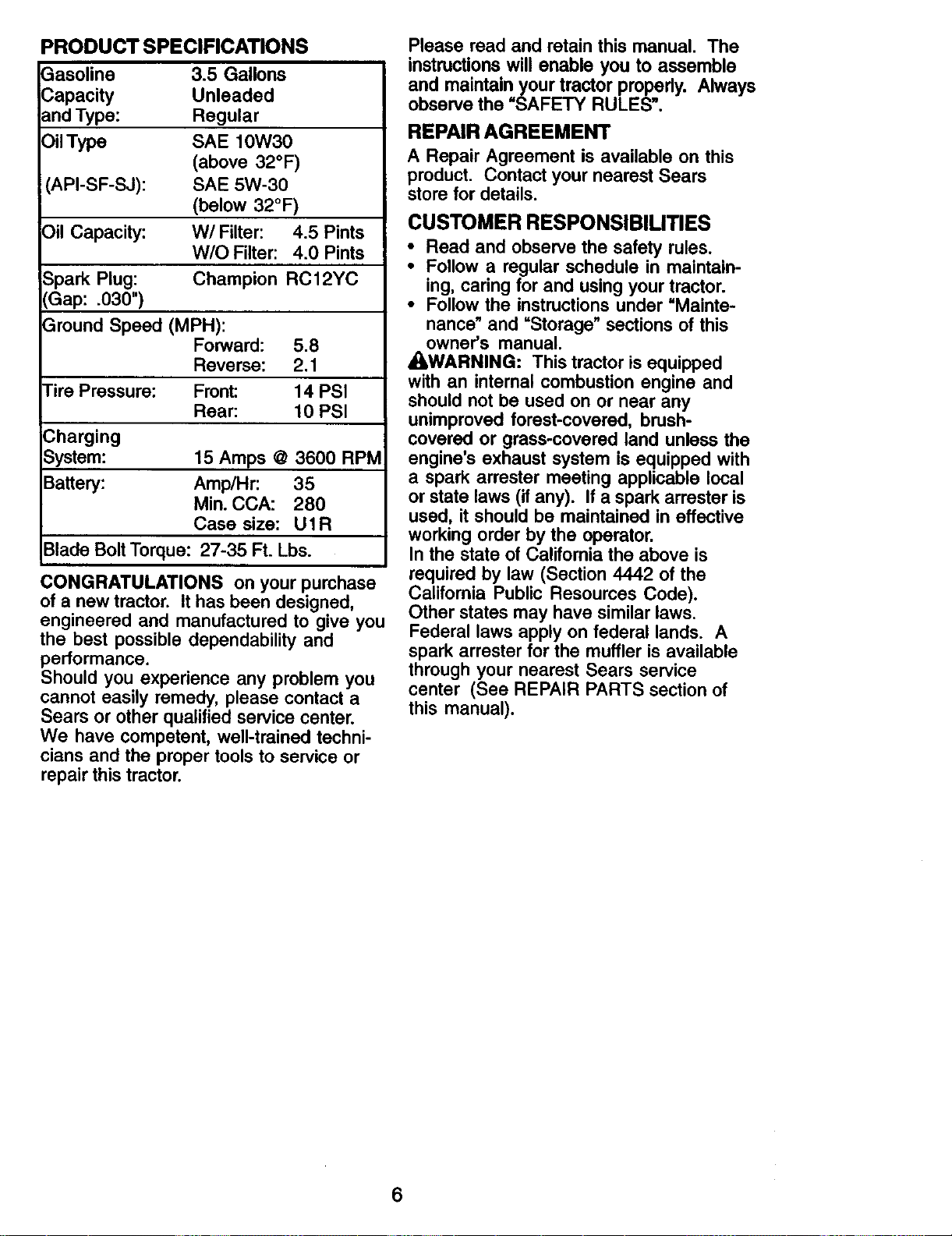
PRODUCT SPECIFICATIONS
Gasoline
Capacity
and Type:
Oil Type
3.5 Gallons
Unleaded
Regular
SAE 10W30
(above 32°F)
(API-SF-SJ): SAE 5W-30
(below 32°F)
_)il Capacity: W/Filter: 4.5 Pints
W/O Filter: 4.0 Pints
Spark Plug: Champion RC12YC
'_Gap: .030")
3round Speed (MPH):
Forward: 5.8
Reverse: 2.1
tire Pressure: Front: 14 PSI
Rear: 10 PSI
_harging
System: 15 Amps @ 3600 RPM
Battery: Amp/Hr: 35
Min. CCA: 280
Case size: U1R
Blade Bolt Torque: 27-35 Ft. Lbs.
CONGRATULATIONS on your purchase
of a new tractor. It has been designed,
engineered and manufactured to give you
the best possible dependability and
performance.
Should you experience any problem you
cannot easily remedy, please contact a
Sears or other qualified service center.
We have competent, well-trained techni-
cians and the proper tools to service or
repair this tractor.
Please read and retain this manual. The
instructionswill enable you to assemble
and maintainyour tractor properly. Always
observethe "SAFETY RULES'.
REPAIR AGREEMENT
A Repair Agreement is available on this
product. Contact your nearest Sears
store for details.
CUSTOMER RESPONSIBILITIES
• Read and observe the safety rules.
• Follow a regular schedule in maintain-
ing, caring for and using your tractor.
• Follow the instructions under "Mainte-
nance" and "Storage" sections of this
owner's manual.
_WARNING: This tractor is equipped
with an internal combustion engine and
should not be used on or near any
unimproved forest-covered, brush-
covered or grass-covered land unless the
engine's exhaust system is equipped with
a spark arrester meeting applicable local
or state laws (if any). If a spark arrester is
used, it should be maintained in effective
working order by the operator.
In the state of Califomia the above is
required by law (Section 4442 of the
Califomia Public Resources Code).
Other states may have similar laws.
Federal laws apply on federal lands. A
spark arrester for the muffler is available
through your nearest Sears service
center (See REPAIR PARTS section of
this manual).
6
Steering Wheel
Steering Sleeve
Steering Sleeve
Extension
Steering Wheel Insert
(1) Washer
17/32 x 1-3/16 x 12 Gauge
(1) Knob b
(2)Flanged
Pins
(1)Front Plate
Assembly
Mower
(5) Retainer Springs
oop)
2) Retainer Springs
single loop)
Gauge Wheels
B
(2) Shoulder
Bolts
Wheels
(2) Washers 3/8
x 7/8 x 14 Gauge
Q(2) Center-
lock Nuts
"7
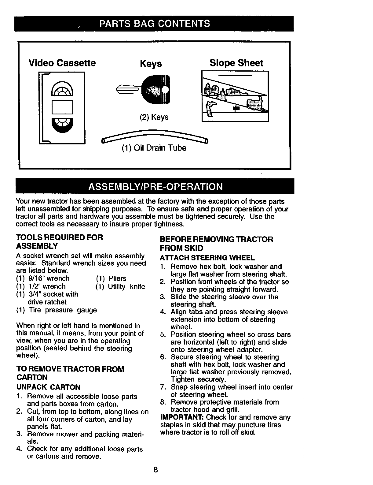
Video Cassette
Keys
Slope Sheet
Your new tractor has been assembled at the factory with the exception of those parts
left unassembled for shipping purposes. To ensure safe and proper operation of your
tractor all parts and hardware you assemble must be tightened securely. Use the
correct tools as necessary to insure proper tightness.
TOOLS REQUIRED FOR
ASSEMBLY
A socket wrench set will make assembly
easier. Standard wrench sizes you need
are listed below.
(1) 9/16" wrench (1) Pliers
(1) 1/2"wrench (1) Utility knife
(1) 3/4" socket with
drive ratchet
(1) Tire pressure gauge
When right or left hand is mentioned in
this manual, it means, from your point of
view, when you are in the operating
position (seated behind the steering
wheel).
TO REMOVE TRACTOR FROM
CARTON
UNPACK CARTON
1. Remove all accessible loose parts
and parts boxes from carton.
2. Cut, from top to bottom, along lines on
all four corners of carton, and lay
panels flat.
3. Remove mower and packing mated-
als.
4. Check for any additional loose parts
or cartons and remove.
BEFORE REMOVING TRACTOR
FROM SKID
ATTACH STEERING WHEEL
1. Remove hex bolt, lock washer and
large flat washer from steering shaft.
2. Position front wheels of the tractor so
they are pointing straight forward.
3. Slide the steering sleeve over the
steering shaft.
4. Align tabs and press steering sleeve
extension into bottom of steering
wheel.
5. Position steering wheel so cross bars
are horizontal (left to right) and slide
onto steering wheel adapter.
6. Secure steering wheel to steedng
shaft with hex bolt, lock washer and
large flat washer previously removed.
Tighten securely.
7. Snap steering wheel insert into center
of steering wheel.
8. Remove prote_;tive materials from
tractor hood and grill.
IMPORTANT: Check for and remove any
staples in skid that may puncture tires
where tractor is to roll off skid.
8
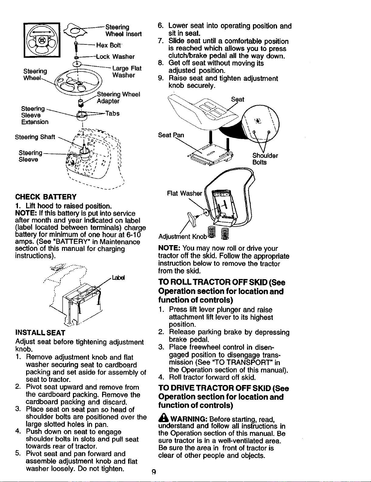
_-,'_ Wheel Insert
_[_-----H:x Bolt
€_------Lock Washer
Steering _ Large Flat
_/Steering Wheel
_" Adapter
Steedng -_ ,
Sleeve __=="-Tabs
Extension t
Steering Shaft
Steering
Sleeve
CHECK BA'rrERY
1. Lift hood to raised position.
NOTE: If this battery is put into service
after month and year indicated on label
(label located between terminals) charge
battery for minimum of one hour at 6-10
amps. (See "BATTERY" in Maintenance
section of this manual for charging
instructions).
"_;-'°. ....... ;,
, ::'-,, ,'" io"
INSTALL SEAT
Adjust seat before tightening adjustment
knob.
1. Remove adjustment knob and flat
washer securing seat to cardboard
packing and set aside for assembly of
seat to tractor.
2. Pivot seat upward and remove from
the cardboard packing. Remove the
cardboard packing and discard.
3. Place seat on seat pan so head of
shoulder bolts are positioned over the
large slotted holes in pan.
4. Push down on seat to engage
shoulder bolts in slots and pull seat
towards rear of tractor.
5. Pivot seat and pan forward and
assemble adjustment knob and flat
washer loosely. Do not tighten.
6. Lower seat into operating position and
sit in seat.
7. Slide seat until a comfortable position
is reached which allows you to press
clutcl'dbrake pedal all the way down.
8. Get off seat without moving its
adjusted position.
9. Raise seat and tighten adjustment
knob securely.
Seat
Seat
Bolts
Flat Washer t
NOTE: Youmay now rollor drive your
tractor offthe skid. Followthe appropriate
instructionbelow to removethe tractor
from the skid.
TO ROLL TRACTOR OFF SKID (See
Operation section for location and
function of controls)
1. Press lift lever plunger and raise
attachment lift lever to its highest
position.
2. Release parking brake by depressing
brake pedal.
3. Place freewheel control in disen-
gaged position to disengage trans-
mission (See =TO TRANSPORT" in
the Operation section of this manual).
4. Roll tractor forward off skid.
TO DRIVE TRACTOR OFF SKID (See
Operation section for location and
function of controls)
A
dUb.WARNING: Before starting read,
unoerstand and fo ow a l instructions in
the Operation section of this manual. Be
sure tractor is in a well-ventilated area.
Be sure the area in front of tractor is
clear of other people and objects.
_q
1. Be sure all the above assembly steps
have been completed.
2. Check engine oil level and fill fuel
tank with gasoline.
3. Place freewheel control in "transmis-
sion engaged" position (see "TO
TRANSPORT" in Operation section of
this manual).
4. Sit on seat in operating position,
depress brake pedal and set the
parking brake.
5. Press lift lever plunger and raise
attachment lift lever to its highest
position.
6. Start the engine. After engine has
started, move throttle control to idle
position.
7. Release parking brake.
8. Slowly move the motion control lever
forward and slowly drive tractor off
skid.
9. Apply brake to stop tractor and set
parking brake.
10.Turn ignition key to "STOP" position.
Continue with the instructions that follow.
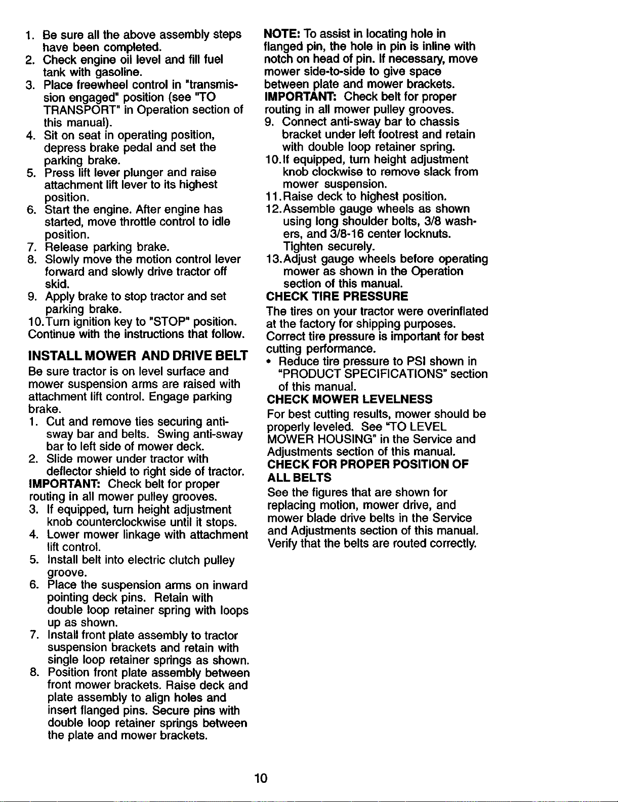
INSTALL MOWER AND DRIVE BELT
Be sure tractor is on level surface and
mower suspension arms are raised with
attachment lift control. Engage parking
brake.
1. Cut and remove ties securing anti-
sway bar and belts. Swing anti-sway
bar to left side of mower deck.
2. Slide mower under tractor with
deflector shield to right side of tractor.
IMPORTANT: Check belt for proper
routing in all mower pulley grooves.
3. If equipped, turn height adjustment
knob counterclockwise until it stops.
4. Lower mower linkage with attachment
lift control.
5. Install belt into electric clutch pulley
groove.
6. Place the suspension arms on inward
pointing deck pins. Retain with
double loop retainer spring with loops
up as shown.
7. Install front plate assembly to tractor
suspension brackets and retain with
single loop retainer springs as shown.
8. Position front plate assembly between
front mower brackets. Raise deck and
plate assembly to align holes and
insert flanged pins. Secure pins with
double loop retainer springs between
the plate and mower brackets.
NOTE: To assist in locating hole in
flanged pin, the hole in pin is inline with
notch on head of pin. If necessary, move
mower side-to-side to give space
between plate and mower brackets.
IMPORTANT: Check belt for proper
routing in all mower pulley grooves.
9. Connect anti-sway bar to chassis
bracket under left footrest and retain
with double loop retainer spring.
10.If equipped, tum height adjustment
knob clockwise to remove slack from
mower suspension.
11. Raise deck to highest position.
12.Assemble gauge wheels as shown
using long shoulder bolts, 3/8 wash-
ers, and 3/8o16 center Iocknuts.
Tighten securely.
13.Adjust gauge wheels before operating
mower as shown in the Operation
section of this manual.
CHECK TIRE PRESSURE
The tires on your tractor were overinflated
at the factory for shipping purposes.
Correct tire pressure is important for best
cutting performance.
• Reduce tire pressure to PSI shown in
"PRODUCT SPECIFICATIONS" section
of this manual.
CHECK MOWER LEVELNESS
For best cutting results, mower should be
propedy leveled. See "TO LEVEL
MOWER HOUSING" in the Service and
Adjustments section of this manual.
CHECK FOR PROPER POSITION OF
ALL BELTS
See the figures that are shown for
replacing motion, mower drive, and
mower blade drive belts in the Service
and Adjustments section of this manual.
Verify that the belts are routed correctly.
10
Sh0uUer
Bolt
Chassis
Bracket
Double Loop
Retainer
Gau
Wheel
Front
Suspension Mower
Arms Bracket
idler
Front Electric
Suspenl_n Clutch
Brackets Pulley
Front Plate
.P
3/8
Washer
3/8-16
Center
Locknut
Double
Loop
Retainer
Spring
Bar
Double Loop
Retainer Spring
(Inward pointing
deck pins)
Single
Loop
Retainer
Springs
Deflector
Shield
Down
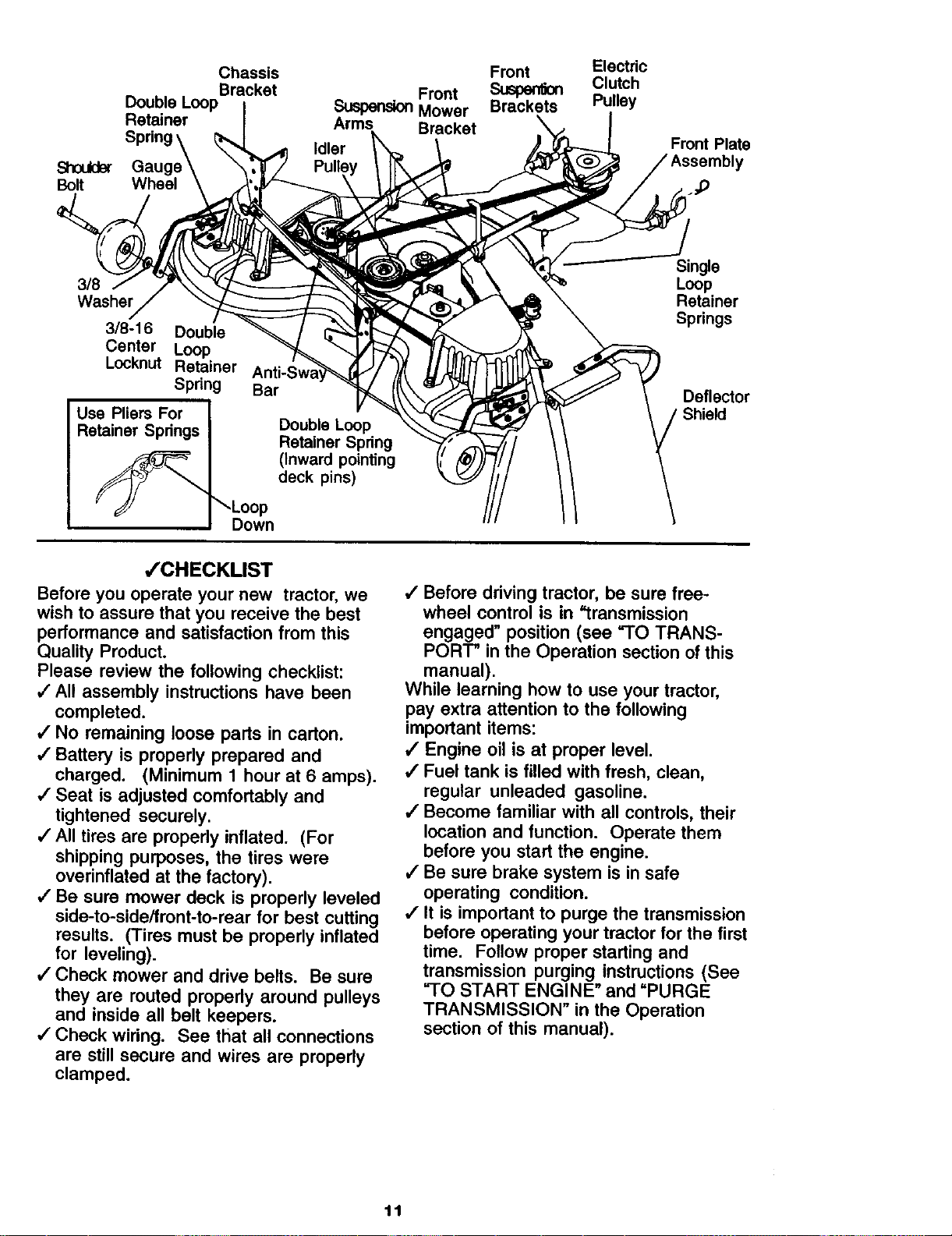
,/'CHECKLIST
Before you operate your new tractor, we
wish to assure that you receive the best
performance and satisfaction from this
Quality Product.
Please review the following checklist:
•/All assembly instructions have been
completed.
J' No remaining loose parts in carton.
•/ Battery is properly prepared and
charged. (Minimum 1 hour at 6 amps).
•/ Seat is adjusted comfortably and
tightened securely.
4 All tires are properly inflated. (For
shipping purposes, the tires were
overinflated at the factory).
•/" Be sure mower deck is properly leveled
side-to-side/front-to-rear for best cutting
results. (Tires must be properly inflated
for leveling).
4"Check mower and drive belts. Be sure
they are routed properly around pulleys
and inside all belt keepers.
,/Check wiring. See that all connections
are still secure and wires are properly
clamped.
4 Before driving tractor, be sure free-
wheel control is in "transmission
engaged" position (see "TO TRANS-
PORT" in the Operation section of this
manual).
While learning how to use your tractor,
pay extra attention to the following
important items:
,I Engine oil is at proper level.
,/Fuel tank is filled with fresh, clean,
regular unleaded gasoline.
4 Become familiar with all controls, their
location and function. Operate them
before you start the engine.
•/ Be sure brake system is in safe
operating condition.
,f It is important to purge the transmission
before operating your tractor for the first
time. Follow proper starting and
transmission purging instructions (See
"-I-O START ENGINE" and "PURGE
TRANSMISSION" in the Operation
section of this manual).
11
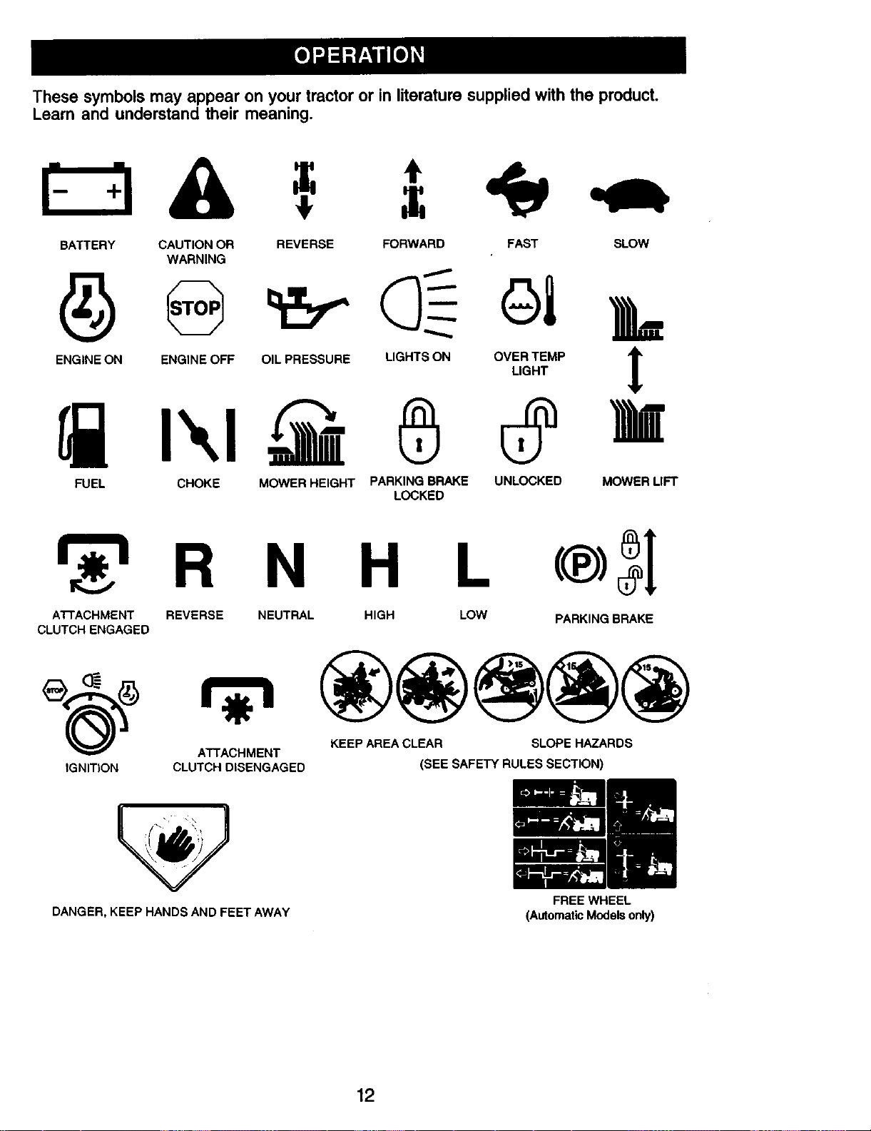
These symbols may appear on your tractor or in literature supplied with the product.
Learn and understand their meaning.
BATTERY CAUTION OR REVERSE FORWARD FAST SLOW
WARNING
A
ENGINE ON ENGINE OFF OIL PRESSURE LIGHTS ON OVER TEMP lr
LIGHT
FUEL CHOKE MOWER HEIGHT PARKING BRAKE UNLOCKED MOWER LIFT
LOCKED
N H L
A'I-rACHMENT REVERSE
CLUTCH ENGAGED
NEUTRAL HIGH LOW
PARKING BRAKE
ATTACHMENT KEEP AREA CLEAR SLOPE HAZARDS
IGNITION CLUTCH DISENGAGED (SEE SAFETY RULES SECTION)
DANGER, KEEP HANDS AND FEET AWAY
12
FREE WHEEL
(AutomaticModelsonly)
KNOW YOUR TRACTOR
READ THIS OWNER'S MANUAL AND SAFETY RULES BEFORE OPERATING
YOUR TRACTOR
Compare the illustrations with your tractor to familiarize yourself with the locations of
various controls and adjustments. Save this manual for future reference.
Motion Drive
Belt Tension
Handle
Choke
Control
Throttle
Control
Brake Pedal
Light Switch
Ammeter Ignition Position
Switch
Attachment
Clutch
Lift
Plunger
Attachment
Lift Lever
Parking Brake
Lever
Height
Adj
Knob
Free
Wheel
Control
Approx.
Speed:
1MPH
Motion Control
Lever
Our tractors conform to the safety standards of the
American National Standards Institute.
ATTACHMENT CLUTCH SWITCH -
Used to engage the mower blades, or
other attachments mounted to your
tractor.
LIGHT SWITCH POSITION- Turns the
headlights on and off.
THROTTLE CONTROL - Used to control
engine speed.
BRAKE PEDAL - Used for braking the
tractor and starting the engine.
CHOKE CONTROL - Used when starting
a cold engine.
HEIGHT ADJUSTMENT KNOB - Used to
adjust the mower cutting height.
IGNITION SWITCH - Used for starting
and stopping the engine.
ATTACHMENT LIFT LEVER - Used to
raise, lower, and adjust the mower deck
or other attachments mounted to your
tractor.
LIFT LEVER PLUNGER - Used to
release attachment lift lever when
changing its position.
AMMETER - Indicates charging (+) or
discharging (-) of battery.
PARKING BRAKE LEVER - Locks brake
pedal into the brake position.
MOTION CONTROL LEVER - Selects the
speed and direction of tractor.
FREEWHEEL CONTROL - Disengages
transmission for pushing or slowly
towing the tractor with the engine off.
MOTION DRIVE BELT TENSION
HANDLE-Used when changing motion
drive belt and, if necessary, starting
engine under extremely cold conditions.
1."4
The operation of any tractor can result in foreign objects thrown into the I
eyes, which can result in severe eye damage. Always wear safety glasses I
or eye shields while operating your tractor or performing any adjustments I
or repairs. We recommend standard safety glasses or a wide vision safety I
mask worn over spectacles. I
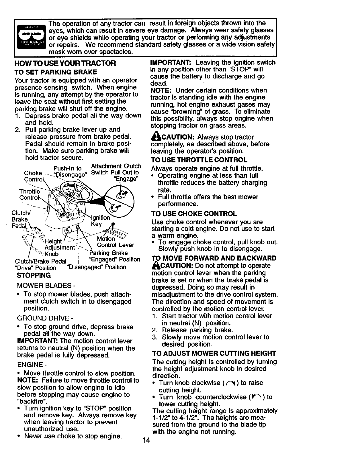
HOWTO USEYOURTRACTOR
TO SET PARKING BRAKE
Your tractor is equipped with an operator
presence sensing switch. When engine
is running, any attempt by the operator to
leave the seat without first setting the
parking brake will shut off the engine.
1. Depress brake pedal all the way down
and hold.
2. Pull parking brake lever up and
release pressure from brake pedal.
Pedal should remain in brake posi-
tion. Make sure parking brake will
hold tractor secure.
Push-In to Attachment Clutch
Choke ,,Disen,_a,_e, SwitchPullOut to
Control _.._ "Engage"
Clutch/ /_ _p]/I_- _ .....
Brake / _ -,y.,uu. --
Keyj
_L AFI'= t t: \ Control Lever
/ _Knob -Parking Brake
Clutch/Brake Pedal "Engaged" Position
"Drive" Position "Disengaged" Position
STOPPING
MOWER BLADES -
• To stop mower blades, push attach-
ment clutch switch in to disengaged
position.
GROUND DRIVE -
• To stop ground drive, depress brake
pedal all the way down.
IMPORTANT: The motion control lever
returns to neutral (N) position when the
brake pedal is fully depressed.
ENGINE -
• Move throttle control to slow position.
NOTE: Failure to move throttle control to
slow position to allow engine to idle
before stopping may cause engine to
"backfire".
• Turn ignition key to "STOP" position
and remove key. Always remove key
when leaving tractor to prevent
unauthorized use.
• Never use choke to stop engine.
IMPORTANT: Leaving the ignition switch
in any position other than "STOP" will
cause the battery to discharge and go
dead.
NOTE: Under certain conditions when
tractor is standing idle with the engine
running, hot engine exhaust gases may
cause "browning" of grass. To eliminate
this possibility, always stop engine when
stopping tractor on grass areas.
_IkCAUTION: Always stop tractor
completely, as described above, before
leaving the operator's position.
TO USE THROTTLE CONTROL
Always operate engine at full throttle.
• Operating engine at less than full
throttle reduces the battery charging
rate.
• Full throttle offers the best mower
performance.
TO USE CHOKE CONTROL
Use choke control whenever you are
starting a cold engine. Do not use to start
a warm engine.
• To engage choke control, pull knob out.
Slowly push knob in to disengage.
TO MOVE FORWARD AND BACKWARD
_L,CAUTION: Do not attemptto operate
motion control lever when the parking
brake is set or when the brake pedal is
depressed. Doing so may result in
misadjustment to the drive control system.
The direction and speed of movement is
controlled by the motion control lever.
1. Start tractor with motion control lever
in neutral (N) position.
2. Release parking brake.
3. Slowly move motion control lever to
desired position.
TO ADJUST MOWER CUTTING HEIGHT
The cutting height is controlled by turning
the height adjustment knob in desired
direction.
• Turn knob clockwise (F_) to raise
cutting height.
• Turn knob counterclockwise (l_)to
lower cutting height.
The cutting height range is approximately
1-1/2" to 4-1/2". The heights are mea-
sured from the ground to the blade tip
with the engine not running.
14
These heights are approximate and may
vary depending upon soil conditions,
height of grass and types of grass being
mowed.
• The average lawn should be cut to
approximately 2-1/2 inches during the
cool season and to over 3 inches
during hot months. For healthier and
better looking lawns, mow often and
after moderate growth.
• For best cutting performance, grass
over 6 inches in height should be
mowed twice. Make the first cut
relatively high; the second to desired
height.
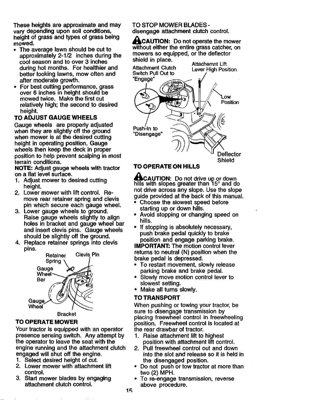
TO ADJUST GAUGE WHEELS
Gauge wheels are properly adjusted
when they are slightly off the ground
when mower is at the desired cutting
height in operating position. Gauge
wheels then keep the deck in proper
position to help prevent scalping in most
terrain conditions.
NOTE: Adjust gauge wheels with tractor
on a fiat level surface.
1. Adjust mower to desired cutting
height.
2. Lower mower with lift control. Re-
move rear retainer spring and clevis
pin which secure each gauge wheel.
3. Lower gauge wheels to ground.
Raise gauge wheels slightly to align
holes in bracket and gauge wheel bar
and insert clevis pins. Gauge wheels
should be slightly off the ground.
4. Replace retainer springs into clevis
pins.
Retainer Clevis Pin
Spring \
Gauge _ L
Gauge_ _
Wheel !
Bracket
TO OPERATE MOWER
Your tractor is equipped with an operator
presence sensing switch. Any attempt by
the operator to leave the seat with the
engine running and the attachment clutch
engaged will shut off the engine.
I. Select desired height of cut.
2. Lower mower with attachment lift
control.
3. Start mower blades by engaging
attachment clutch control.
TO STOP MOWER BLADES -
disengage attachment clutch control.
_CAUTION: Do not operate the mower
without either the entire grass catcher, on
mowers so equipped, or the deflector
shield in place.
Attachemnt Lift
Attachment Clutch Lever HighPosition
Switch PullOut to
_._-_, )lI=_ _// _-_j_,::'._ Position
: "_} )'Disengage"_" __lector
Shield
TO OPERATE ON RILLS
x_
_CAUTION: Do not drive up or down
hills with slopes greater than 15° and do
not drive across any slope. Use the slope
guide provided at the back of this manual.
• Choose the slowest speed before
starting up or down hills.
• Avoid stopping or changing speed on
hills.
• If stopping is absolutely necessary,
push brake pedal quickly to brake
position and engage parking brake.
IMPORTANT: The motion control lever
returns to neutral (N) position when the
brake pedal is depressed.
• To restart movement, slowly release
parking brake and brake pedal.
• Slowly move motion control lever to
slowest setting.
• Make all turns slowly.
TO TRANSPORT
When pushing or towing your tractor, be
sure to disengage transmission by
placing freewheel control in freewheeling
position. Freewheel control is located at
the rear drawbar of tractor.
1. Raise attachment lift to highest
position with attachment lift control.
2. Pull freewheel control out and down
into the slot and release so it is held in
the disengaged position.
• Do not push or tow tractor at more than
two (2) MPH.
• To re-engage transmission, reverse
above procedure.
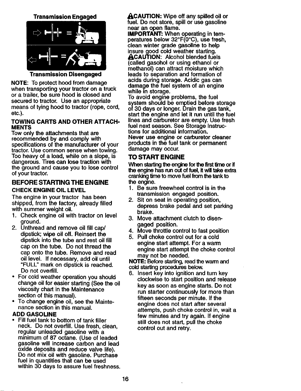
Transmission Engaged
Transmission Disengaged
NOTE: To protect hood from damage
when transporting your tractor on a truck
or a trailer, be sure hood is closed and
secured to tractor. Use an appropriate
means of tying hood to tractor (rope, cord,
etc.).
TOWING CARTS AND OTHER ATTACH-
MENTS
Tow only the attachments that are
recommended by and comply with
specifications of the manufacturer of your
tractor. Use common sense when towing.
Too heavy of a load, while on a slope, is
dangerous. "l]res can lose traction with
the ground and cause you to lose control
of your tractor.
BEFORE STARTING THE ENGINE
CHECK ENGINE OIL LEVEL
The engine in your tractor has been
shipped, from the factory, already filled
with summer weight oil.
1. Check engine oil with tractor on level
ground.
2. Unthread and remove oil fill cap/
dipstick; wipe oil off. Reinsed the
dipstick into the tube and rest oil fill
cap on the tube. Do not thread the
cap onto the tube. Remove and read
oil level. If necessary, add oil until
"FULL" mark on dipstick is reached.
Do not overfill.
• For cold weather operation you should
change oil for easier starting (See the oil
viscosity chart in the Maintenance
section of this manual).
• To change engine oil, see the Mainte-
nance section in this manual.
ADD GASOLINE
• Fill fuel tank to bottom of tank filler
neck. Do not overfill. Use fresh, clean,
re.gular unleaded gasoline with a
minimum of 87 octane. (Use of leaded
gasoline will increase carbon and lead
oxide deposits and reduce valve life).
Do not mix oil with gasoline. Purchase
fuel in quantities that can be used
within 30 days to assure fuel freshness.
_CAUTION: Wipe off any spilled oil or
fuel. Do not store, spill or use gasoline
near an open flame.
IMPORTANT: When operating in tem-
peratures below 32°F(0°C), use fresh,
clean winter grade gasoline to help
insure good cold weather starting.
ACAUTION: Alcohol blended fuels
(called gasohol or using ethanol or
methanol) can attract moisture which
leads to separation and formation of
acids during storage. Acidic gas can
damage the fuel system of an engine
while in storage.
To avoid engine problems, the fuel
system should be emptied before storage
of 3O days or longer. Drain the gas tank,
start the engine and let it run until the fuel
lines and carburetor are empty. Use fresh
fuel next season. See Storage Instruc-
tions for additional information.
Never use engine or carburetor cleaner
products in the fuel tank or permanent
damage may occur.
TO START ENGINE
When startingthe engine forthe firsttime or if
the enginehas runout of fuel, itwill take extra
cranking]time to move fuel from the tank to
the engine.
1. Be sure freewheel control is in the
transmission engaged position.
2. Sit on seat in operating position,
depress brake pedal and set parking
brake.
3. Move attachment clutch to disen-
gaged position.
4. Move throttle control to fast position
5. Pull choke control out for a cold
engine start attempt. For a warm
engine start attempt the choke control
may not be needed.
NOTE: Before starting, read the warm and
cold starting procedures below.
6. Insert key into ignition and turn key
clockwise to start position and release
key as soon as engine starts. Do not
run starter continuously for more than
fifteen seconds per minute. If the
engine does not start after several
attempts, push choke control in, wait a
few minutes and try again. If engine
still does not start, pull the choke
control out and retry.
16
WARM WEATHER STARTING (50° F and
above)
7. When engine starts, slowly push
choke control in until the engine
begins to run smoothly. If the engine
starts to run roughly, pull the choke
control out slightly for a few seconds
and then continue to push the control
in slowly.
• The attachments and ground drive can
now be used. If the engine does not accept
the load, restartthe engine and allow itto
warm upfor one minute using the choke
as described above,
COLD WEATHER STARTING (500 F and
below)
7. When engine starts, slowly push
choke control in until the engine
begins to run smoothly. Continue to
push the choke control in small steps
allowing the engine to accept small
changes in speed and load, until the
choke control is fully in. If the engine
starts to run roughly, pull the choke
control out slightly for a few seconds
and then continue to push the control
in slowly. This may require an engine
warm-up period from several seconds
to several minutes, depending on the
temperature.
NOTE: In extreme cold conditions, if
engine will not start you may need to
disengage the motion drive belt as
follows:
1. Be sure parking brake is engaged.
2. Remove retainer spring from the drive
belt tension handle to relieve belt
tension.
3. Start engine and allow it to warm up
for three (3) minutes.
4. Shut-oft engine and engage parking
brake.
5. Engage drive belt tension handle and
replace the retainer spring.
AUTOMATIC TRANSMISSION WARM UP
Before driving the unit in cold weather,
the transmission should be warmed up as
follows:
1. Be sure the tractor is on level ground.
2. Place the motion control lever in
neutral. Release the parking brake
and let the brake slowly return to
operating position.
3. Allow one minute for transmission to
warm up. This can be done during the
engine warm up period.
• The attachments can be used during
the engine warm-up pedod after the
transm,ssion has been warmed up and
may require the choke control be
pulled out slightly.
NOTE: If at a high altitude (above 3000
feet) or in cold temperatures (below 32 F)
the carburetor fuel mixture may need to
be adjusted for best engine performance.
(See "TO ADJUST CARBURETOR" in the
Service and Adjustments section of this
manual.)
PURGE TRANSMISSION
_bCAUTION: Never engage or disen-
gage freewheel lever while the engine is
running.
To ensure proper operation and perfor-
mance, it is recommended that the
transmission be purged before operating
tractor for the firsttime. This procedure will
remove any trapped air inside the trans-
mission which may have developed during
shipping of your tractor.
IMPORTANT: Should your transmission
require removal for service or replacement,
it should be purged after reinstailation
before operating the tractor.
1. Place tractor safely on level surface
with engine off and parking brake set.
2. Disengage transmission by placing
freewheel control in disengaged
position (See "TO TRANSPORT" in
this section of manual).
3. Sitting in the tractor seat, start engine.
After the engine is running, move
throttle control to slow position.
Disengage parking brake.
4. Move motion control lever to full
forward position and hold for five (5)
seconds. Move lever to full reverse
position and hold for five (5) seconds.
Repeat this procedure three (3) times.
NOTE: During this step there will be no
movement of drive wheels. The air is being
removed from hydraulic drive system.
5. Move motion control lever to neutral
(N) position, Shutoff engine and set
parking brake.
6. Engage transmission by placing
freewheel control in engaged position
(See "TO TRANSPORT" in this section
of manual).
7. Sitting in the tractor seat, start engine.
After the engine is running, move
throttle control to half (1/2) speed.
Disengage parking brake.
1"7
8. Slowly move motion control lever f
forward, after the tractor moves A
approximately five (5) feet, slowly
l
move motion control lever to reverse
position. After the tractor moves
approximately five (5) feet retum the
motion control lever to the neutral (N) _-_.
position. Repeat this procedure with
the motion control lever three (3)
times.
Your transmission is now purged and now
ready for normal operation.
MOWING TIPS
• Mower shouldbe properlyleveled for
best mowing performance. See =TO
LEVEL MOWER HOUSING" in the
Service and Adjustments section of this
manual.
• The left hand side of mower shouldbe
used for trimming.
• Drive so that clippingsare discharged
onto the area that has already been
cut. Have the cut area to the rightof the
tractor. This wilt resultin a more even
distributionof clippingsand more
uniformcutting.
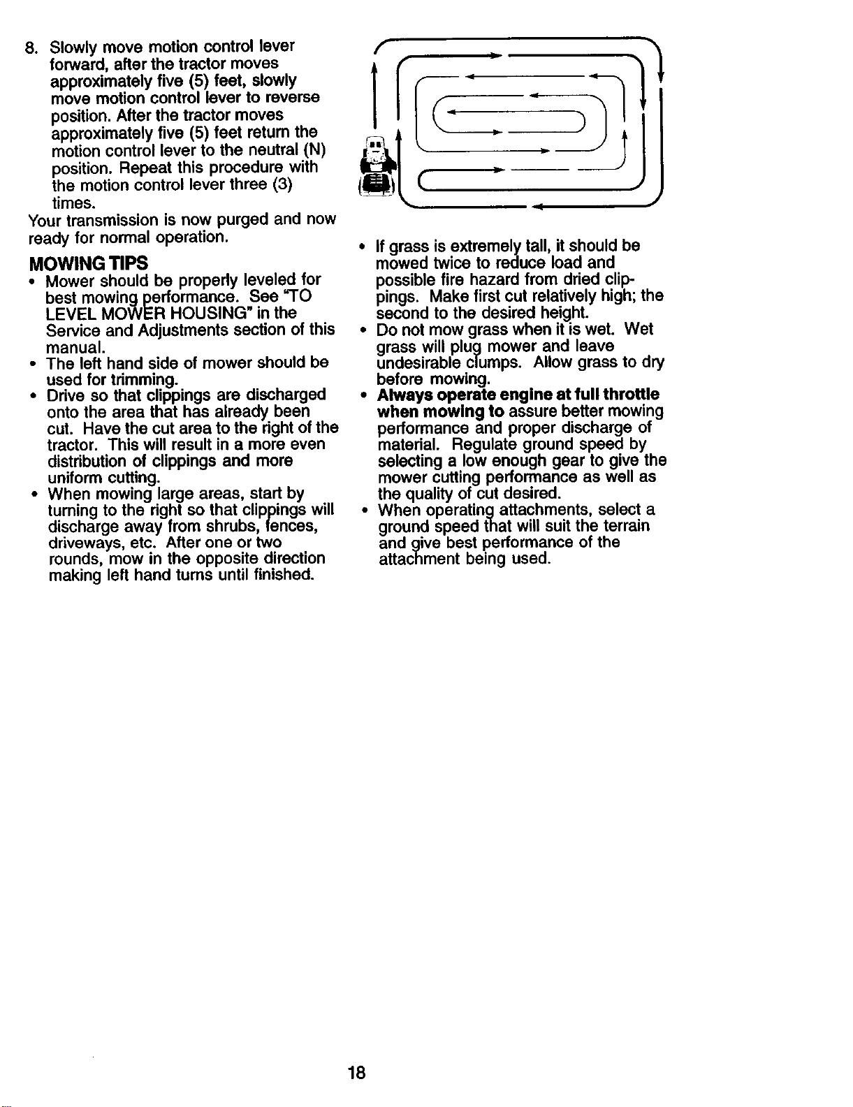
• When mowing large areas, start by
tuming to the rightso that clippingswill
dischargeaway from shrubs, fences,
driveways, etc. After one or two
rounds, mow in the opposite direction
making left hand turns untilfinished.
D
• If grass is extremely tall, it should be
mowed twice to reduce load and
possible fire hazard from dried clip-
pings. Make first cut relatively high; the
second to the desired height.
• Do not mow grass when it is wet. Wet
grass will plug mower and leave
undesirable clumps. Allow grass to dry
before mowing.
• Always operate engine at full throttle
when mowing to assure better mowing
performance and proper discharge of
material. Regulate ground speed by
selecting a low enough gear to give the
mower cutting performance as well as
the quality of cut desired.
• When operatingattachments, select a
ground speed that will suit the terrain
and give best performance of the
attachment being used.
18
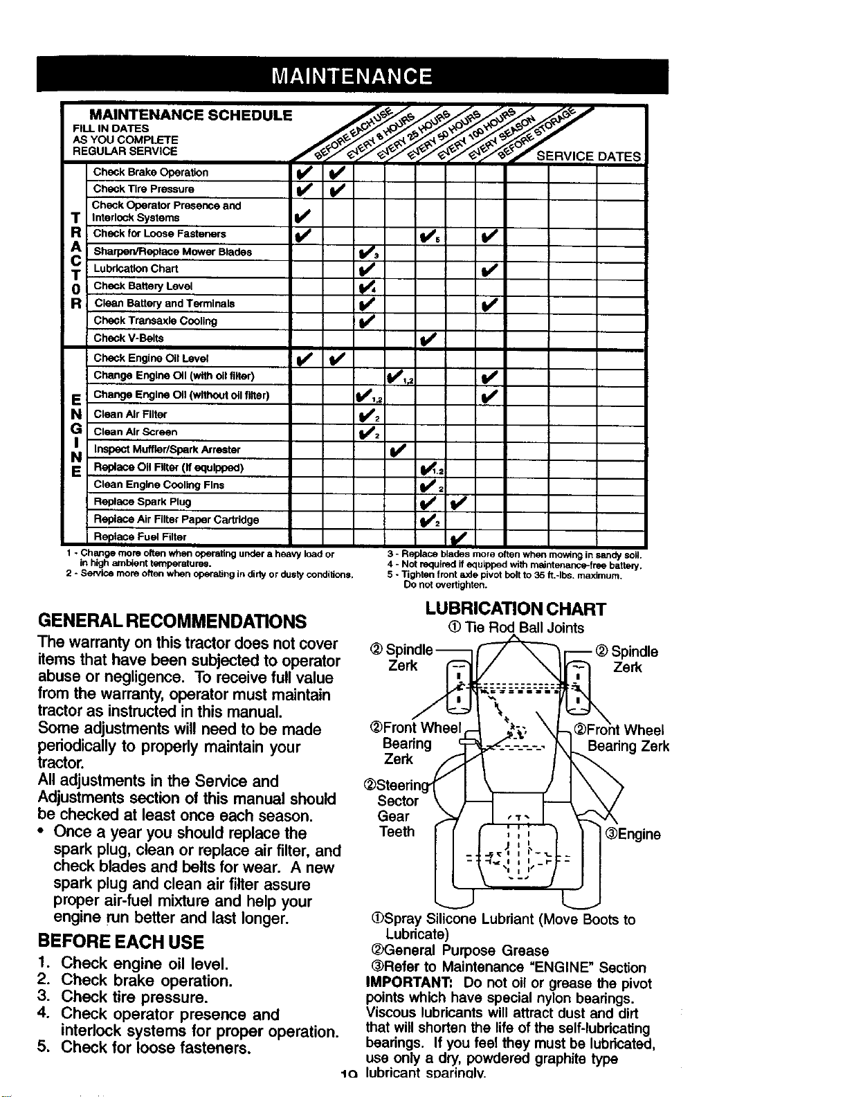
MAINTENANCE SCHEDULE /_-_- _,_. ____'_°_
FILL IN DATES
AS YOU COMPLETE ___ j______. _ _
REGULAR SERVICE
Check Brake Operation
Check Tire Pressure _' _
Check Operator Presence and
T Interlock Systems
R Check for Loose Fasteners
A Sharpen/Replace Mower Blades
T Lubrication Chart
0 Check Battery Level
R c_een Battery and Terminals
Check Transaxle Cooling
Check V-Belts
Check Engine Oil Level
Change Engine 011 (with oil finer)
E Change Engine OII (without oll filter)
N creenAirFilter
G clean Air Screen
i_ Inspect Muffler/Spark
Arrester
E Replace OII Riter (If equipped)
Clean Engine Cooling Fins
Replace Spark Plug
Replace Air Filter Paper Cartridge
Replace Fuel Filter
1 * Change more often when operating under a heavy load or 3 - Replace blades more often when mowing in sandy soil.
in high ambient temperatures. 4 - Not required if equipped with maintenance-free battenj.
2 - Service more often when operat}ng in dirty or dusty conditions. 5 - Tighten front axle pivot bolt to 35 ft.-Ibs, maximum.
Do not overtighten.
_' v', v'
l/
v'
v'
v' i,,
;
=/
I/2
V'
GENERAL RECOMMENDATIONS
The warranty on this tractor does not cover
items that have been subjected to operator
abuse or negligence. To receive full value
from the warranty, operator must maintain
tractor as instructed in this manual.
Some adjustments will need to be made
periodically to property maintain your
tractor.
All adjustments in the Service and
Adjustments section of this manual should
be checked at least once each season.
• Once a year you should replace the
spark plug, clean or replace air filter, and
check blades and belts for wear. A new
spark plug and clean air filter assure
proper air-fuel mixture and help your
engine run better and last longer.
BEFORE EACH USE
1. Check engine oil level.
2. Check brake operation.
3. Check tire pressure.
4. Check operator presence and
interlock systems for proper operation.
5. Check for loose fasteners.
LUBRICATION CHART
"13eRod BallJoints
(_FrontWheel c-
Bearing c
Zerk f
(_Steedng_ /
Sector \
Gear t
Teeth
_ _F_- _ Spindle
=__.:::=::_ Zerk
_, -'_=--'_-'-'2;:.
a,:
S,'_,_ Whos'
='_'------'-.--.- Beadng Zerk
'',I I ®Engina
"-,_" j
(DSpray SiliCone Lubriant (MoveBoots to
Lubricate)
(_General Purpose Grease
(3_Refer to Maintenance "ENGINE" Section
IMPORTANT: Do not oil or grease the pivot
points which have special nylon bearings.
Viscous lubricants will attract dust and dirt
that will shorten the life of the self-lubricating
bearings. If you feel they must be lubricated,
use only a dry, powdered graphite type
t<_ lubricant sDarinelv.
TRACTOR
Always observe safety rules when
performing any maintenance.
BRAKE OPERATION
If tractor requires more than six (6) feet
stopping distance at high speed in
highest gear, then brake must be ad-
justed. (See "TO ADJUST BRAKE" in the
Service and Adjustments section of this
manual).
TIRES
• Maintain proper air pressure in all tires
(See "PRODUCT SPECIFICATIONS"
section of this manual).
• Keep tires free of gasoline, oil, or insect
control chemicals which can harm
rubber.
• Avoid stumps, stones, deep ruts, sharp
objects and other hazards that may
cause tire damage.
NOTE: To seal tire punctures and prevent
flat tires due to slow leaks, tire sealant
may be purchased from your local parts
dealer. Tire sealant also prevents tire dry
rot and corrosion.
OPERATOR PRESENCE SYSTEM
Be sure that operator presence and
interlock systems are working properly. If
your tractor does not function as de-
scribed below, repair the problem
immediately.
• The engine should not start unless the
brake pedal is fully depressed and
attachment clutch control is in the
disengaged position.
• When the engine is running, any
attempt by the operator to leave the
seat without first setting the parking
brake should shut off the engine.
• When the engine is running and the
attachment clutch is engaged, any
attempt by the operator to leave the
seat should shut off the engine.
• The attachment clutch should never
operate unless the operator is in the
seat.
BLADE CARE
For best results mower blades must be
kept sharp. Replace bent or damaged
blades.
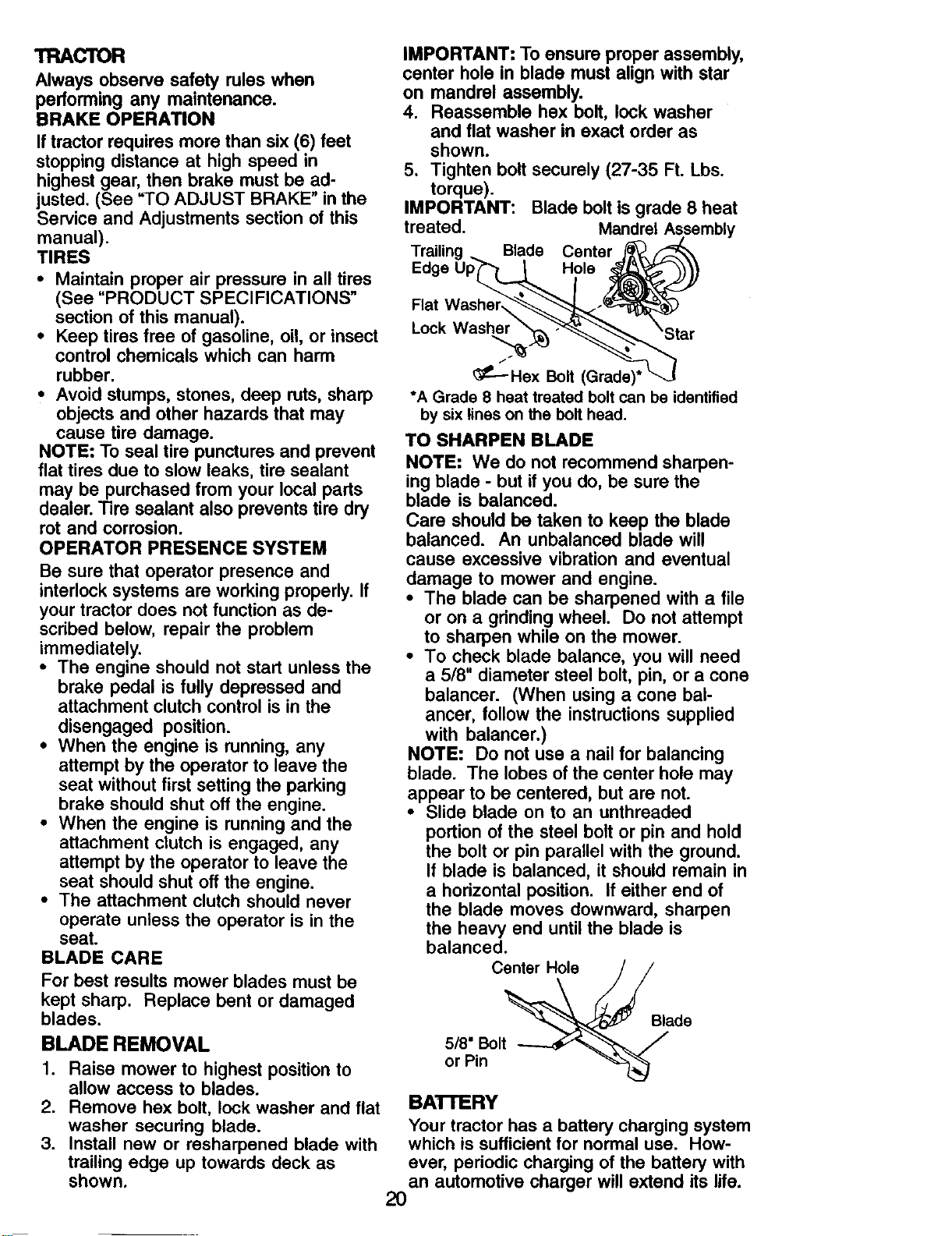
IMPORTANT: To ensure proper assembly,
center hole in blade must align with star
on mandrel assembly.
4. Reassemble hex bolt, lock washer
and flat washer in exact order as
shown.
5. Tighten bolt securely (27-35 Ft. Lbs.
torque).
IMPORTANT: Blade bolt is grade 8 heat
treated. Mandrel Assembly
Trailing Blade Center
Edge Hole
Flat
Lock Washer
/
Hex Bolt (Grade)*
*A Grade 8 heat treated boltcan be identified
by sixlines onthe bolthead.
TO SHARPEN BLADE
NOTE: We do not recommend sharpen-
ing blade - but if you do, be sure the
blade is balanced.
Care should be taken to keep the blade
balanced. An unbalanced blade will
cause excessive vibration and eventual
damage to mower and engine.
• The blade can be sharpened with a file
or on a grinding wheel. Do not attempt
to sharpen while on the mower.
• To check blade balance, you will need
a 5/8" diameter steel bolt, pin, or a cone
balancer. (When using a cone bal-
ancer, follow the instructions supplied
with balancer.)
NOTE: Do not use a nail for balancing
blade. The lobes of the center hole may
appear to be centered, but are not.
• Slide blade on to an unthreaded
portion of the steel bolt or pin and hold
the bolt or pin parallel with the ground.
If blade is balanced, it should remain in
a horizontal position. If either end of
the blade moves downward, sharpen
the heavy end until the blade is
balanced.
Center Hole
Blade
BLADE REMOVAL
1. Raise mower to highest position to
allow access to blades.
2. Remove hex bolt, lock washer and flat
washer securing blade.
3. Install new or resharpened blade with
trailing edge up towards deck as
shown.
5/8" Bolt
or Pin
BAI"rERY
Your tractor has a battery charging system
which is sufficient for normal use. How-
ever, periodic charging of the battery with
an automotive charger will extend its life.
2O
• Keep battery and terminals clean.
• Keep battery bolts tight.
• Keep small vent holes open.
• Recharge at 6-10 amperes for 1 hour.
NOTE: The original equipment battery on
your tractor is maintenance free. Do not
attempt to open or remove caps or covers.
Adding or checking level of electrolyte is
not necessary.
TO CLEAN BATTERY AND TERMINALS
Corrosion and dirt on the battery and
terminals can cause the battery to "leak"
power.
1. Remove terminal guard.
2. Disconnect BLACK battery cable first
then RED battery cable and remove
battery from tractor.
3. Rinse the battery with plain water and
dry.
4. Clean terminals and battery cable
ends with wire brush until bright.
5. Coat terminals with grease or petro-
leum jelly.
6. Reinstall battery (See "REPLACING
BATTERY" in the SERVICE AND
ADJUSTMENTS section of this
manual).
TRANSAXLE COOLING
The transmission fan and cooling fins
should be kept clean to assure proper
cooling.
Do not attempt to clean fan or transmis-
sion while engine is running or while the
transmission is hot. To prevent possible
damage to seals, do not use high
pressure water or steam to clean
transaxle.
• Inspect cooling fan to be sure fan
blades are intact and clean.
• Inspect cooling fins for dirt, grass
clippings and other materials. To
prevent damage to seals, do not use
compressed air or high pressure
sprayer to clean cooling fins.
TRANSAXLE PUMP FLUID
The transaxle was sealed at the factory
and fluid maintenance is not required for
the life of the transaxle. Should the
transaxle ever leak or require servicing,
contact your nearest Sears or other
qualified service center.
V-BELTS
Check V-belts for deterioration and wear
after t00 hours of operation and replace
if necessary. The belts are not adjustable.
Replace belts if they begin to slip from
wear.
ENGINE
LUBRICATION
Only use high quality detergent oil rated
with API service classification SF-SJ.
Select the oil's SAE viscosity grade
according to your expected operating
temperature.
Change the oil after every 50 hours of
operation or at least once a year if the
tractor is not used for 50 hours in one
year.
Check the crankcase oil level before
starting the engine and after each eight
(8) hours of operation. "13ghtenoil fill cap/
dipstick securely each time you check the
oil level.
TO CHANGE ENGINE OIL
Determine temperature range expected
before oil change. All oil must meet API
service classification SF-SJ.
• Be sure tractor is on level surface.
• Oil will drain more freely when warm.
• Catch oil in a suitable container.
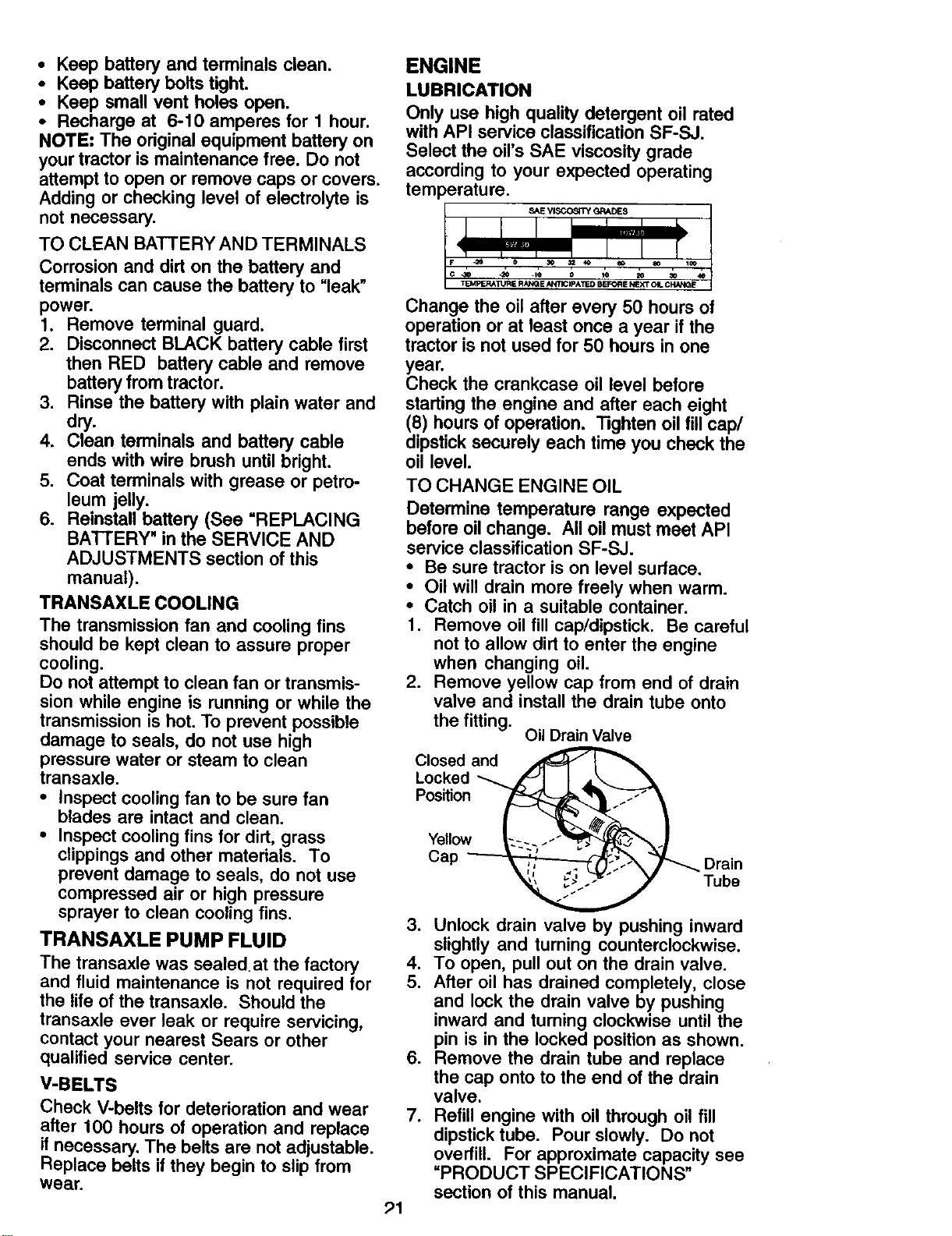
1. Remove oil fill cap/dipstick. Be careful
not to allow dirt to enter the engine
when changing oil.
2. Remove yellow cap from end of drain
valve and install the drain tube onto
the fitting.
Oil Drain Valve
Closed and
Locked
Position
Yellow
Cap
Drain
Tube
91
3. Unlock drain valve by pushing inward
slightly and turning counterclockwise.
4. To open, pull out on the drain valve.
5. After oil has drained completely, close
and lock the drain valve by pushing
inward and turning clockwise until the
pin is in the locked position as shown.
6. Remove the drain tube and replace
the cap onto to the end of the drain
valve.
7. Refill engine with oil through oil fill
dipstick tube. Pour slowly. Do not
overfill. For approximate capacity see
"PRODUCT SPECIFICATIONS"
section of this manual.
8. Use gauge on oil fill cap/dipstick for
checking level. Insert dipstick into the
tube and rest the oil fill cap on the
tube. Do not thread the cap onto the
tube when taking reading. Keep oil
at =FULL" line on dipstick. Tighten cap
onto the tube securely when finished.
ENGINE OIL FILTER
Replace the engine oil filter every season
or every other oil change if the tractor is
used more than 100 hours in one year.
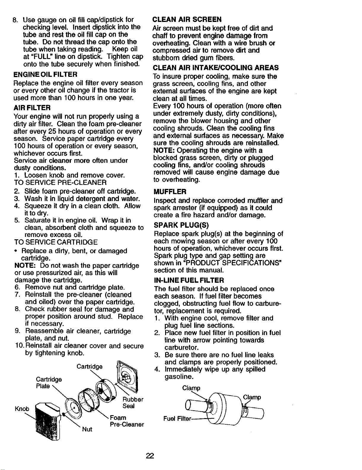
AIR FILTER
Your engine will not run properly using a
dirty air filter. Clean the foam pre-cleaner
after every 25 hours of operation or every
season. Service paper cartridge every
100 hours of operation or every season,
whichever occurs first.
Service air cleaner more often under
dusty conditions.
1. Loosen knob and remove cover.
TO SERVICE PRE-CLEANER
2. Slide foam pre-cleaner off cartridge.
3. Wash it in liquid detergent and water.
4. Squeeze it dry in a clean cloth. Allow
itto dry.
5. Saturate it in engine oil. Wrap it in
clean, absorbent cloth and squeeze to
remove excess oil.
TO SERVICE CARTRIDGE
• Replace a dirty, bent, or damaged
cartridge.
NOTE: Do not wash the paper cartridge
or use pressurized air, as this will
damage the cartridge.
6. Remove nut and cartridge plate.
7. Reinstall the pre-cleaner (cleaned
and oiled) over the paper cartridge.
8. Check rubber seal for damage and
proper position around stud. Replace
if necessary.
9. Reassemble air cleaner, cartridge
plate, and nut.
10. Reinstall air cleaner cover and secure
by tightening knob.
Cartridge
Cartridge
Plate
Knob
Rubber
Seal
'- Foam
Pre-Cleaner
Nut
CLEAN AIR SCREEN
Air screen must be kept free of dirt and
chaff to prevent engine damage from
overheating. Clean with a wire brush or
compressed air to remove dirt and
stubborn dried gum fibers.
CLEAN AIR INTAKE/COOLING AREAS
To insure proper cooling, make sure the
grass screen, cooling fins, and other
external surfaces of the engine are kept
clean at all times.
Every 100 hours of operation (more often
under extremely dusty, dirty conditions),
remove the blower housing and other
cooling shrouds. Clean the cooling fins
and external surfaces as necessary. Make
sure the cooling shrouds are reinstalled.
NOTE: Operating the engine with a
blocked grass screen, dirty or plugged
cooling fins, and/or cooling shrouds
removed will cause engine damage due
to overheating.
MUFFLER
Inspect and replace corroded muffler and
spark arrester (if equipped) as it could
create a fire hazard and/or damage.
SPARK PLUG(S)
Replace spark plug(s) at the beginning of
each mowing season or after every 100
hours of operation, whichever occurs first.
Spark plug type and gap setting are
shown in =PRODUCT SPECIFICATIONS"
section of this manual,
IN-LINE FUEL FILTER
The fuel filter should be replaced once
each season. If fuel filter becomes
clogged, obstructing fuel flow to carbure-
tor, replacement is required.
1. With engine cool, remove filter and
plug fuel line sections.
2. Place new fuel filter in position in fuel
line with arrow pointing towards
carburetor.
3. Be sure there are no fuel line leaks
and clamps are properly positioned.
4. Immediately wipe up any spilled
gasoline.
Cl_mp
Fuel Filter.__ _J
22
CLEANING
• Clean engine,battery, seat,finish, etc.
of all foreign matter.
• Keep finishedsurfaces and wheels free
of all gasoline, oil, etc.
• Protect painted surfaces with automo-
tivetype wax.
We do not recommend using a garden
hose to clean your tractor unless the
electrical system, muffler, air filter and
carburetor are covered to keep water out.
Water in engine can result in a shortened
engine life.
,i_ WARNING: TO AVIOD INJURY, BEFORE PERFORMING ANY
SERIOUS
SERVICE OR ADJUSTMENTS.
1. Depress brake pedal fully and set parking brake.
2. Place attachment clutch in =DISENGAGED" position.
3. Tum ignition key "OFF" and remove key.
4. Make sure the blades and all moving parts have completely stopped.
5. Disconnect spark plug wire from spark plug and place wire where it cannot
come in contact with plug.
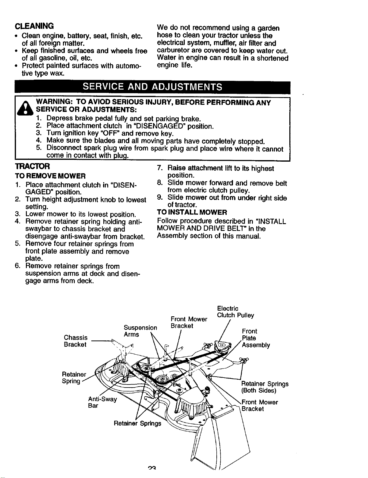
TRACTOR
TO REMOVE MOWER
1. Place attachment clutch in "DISEN-
GAGED" position.
2. Turn height adjustment knob to lowest
setting.
3. Lower mower to its lowest position.
4, Remove retainer spring holding anti-
swaybar to chassis bracket and
disengage anti-swaybar from bracket.
5. Remove four retainer springs from
front plate assembly and remove
plate.
6. Remove retainer springs from
suspension arms at deck and disen-
gage arms from deck.
7. Raise attachment lift to its highest
position.
8. Slide mower forward and remove belt
from electric clutch pulley.
9. Slide mower out from under right side
of tractor.
TO INSTALL MOWER
Follow procedure described in =INSTALL
MOWER AND DRIVE BELl" in the
Assembly section of this manual.
Suspension
Chassis Arms
Bracket --_"-
Front Mower
Bracket
Electric
Clutch Pulley
Front
Plate
Retainer
Spring
Anti-Sway
Bar
Retainer Springs
Retainer Springs
(Both Sides)
Mower
Bracket
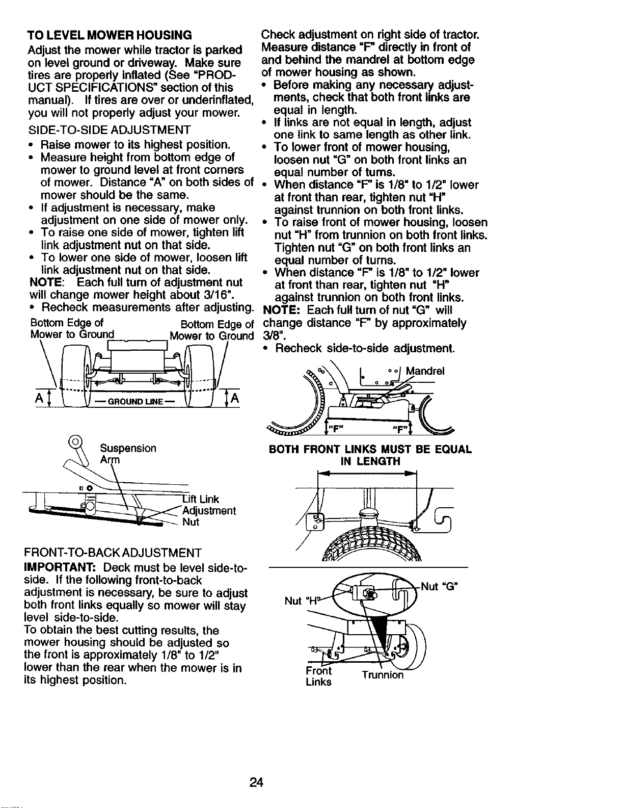
TO LEVEL MOWER HOUSING
Adjust the mower while tractor is parked
on level ground or driveway. Make sure
tires are propedy inflated (See "PROD-
UCT SPECIFICATIONS" section of this
manual). If tires are over or underinflated,
you will not properly adjust your mower.
SIDE-TO-SIDE ADJUSTMENT
• Raise mower to its highest position. •
• Measure height from bottom edge of
mower to ground level at front corners
of mower. Distance "A" on both sides of •
mower should be the same.
• If adjustment is necessary, make
adjustment on one side of mower only. •
• To raise one side of mower, tighten lift
link adjustment nut on that side.
• To lower one side of mower, loosen lift
link adjustment nut on that side. •
NOTE: Each full tum of adjustment nut
will change mower height about 3/16".
Check adjustment on right side of tractor.
Measure distance "F" directly in front of
and behind the mandrel at bottom edge
of mower housing as shown.
• Before making any necessary adjust-
ments, check that both front links are
equal in length.
• If links are not equal in length, adjust
one link to same length as other link.
To lower front of mower housing,
loosen nut "G" on both front links an
equal number of turns.
When distance "F_ is 1/8" to 1/2" lower
at front than rear, tighten nut "H"
against trunnion on both front links.
To raise front of mower housing, loosen
nut "H" from trunnion on both front links.
Tighten nut "G" on both front links an
equal number of turns.
When distance "F" is 1/8" to 1/2" lower
at front than rear, tighten nut "H"
against trunnion on both front links.
• Recheck measurements after adjusting. NOTE: Each full tum of nut =G" will
BottomEdgeof BottomEdge of change distance "F" by approximately
Mower to Ground Mower to Ground 3/8".
• Recheck side-to-side adjustment.
Mandrel
(_ Suspension
JR .,...nk
_Adjustment
_Nut
FRONT-TO-BACK ADJUSTMENT
IMPORTANT: Deck must be level side-to-
side. If the following front-to-back
adjustment is necessary, be sure to adjust
both front links equally so mower will stay
level side-to-side.
To obtain the best cutting results, the
mower housing should be adjusted so
the front is approximately 1/8" to 1/2"
lower than the rear when the mower is in
its highest position.
BOTH FRONT LINKS MUST BE EQUAL
IN LENGTH
Nut
Trunnion
Links
24
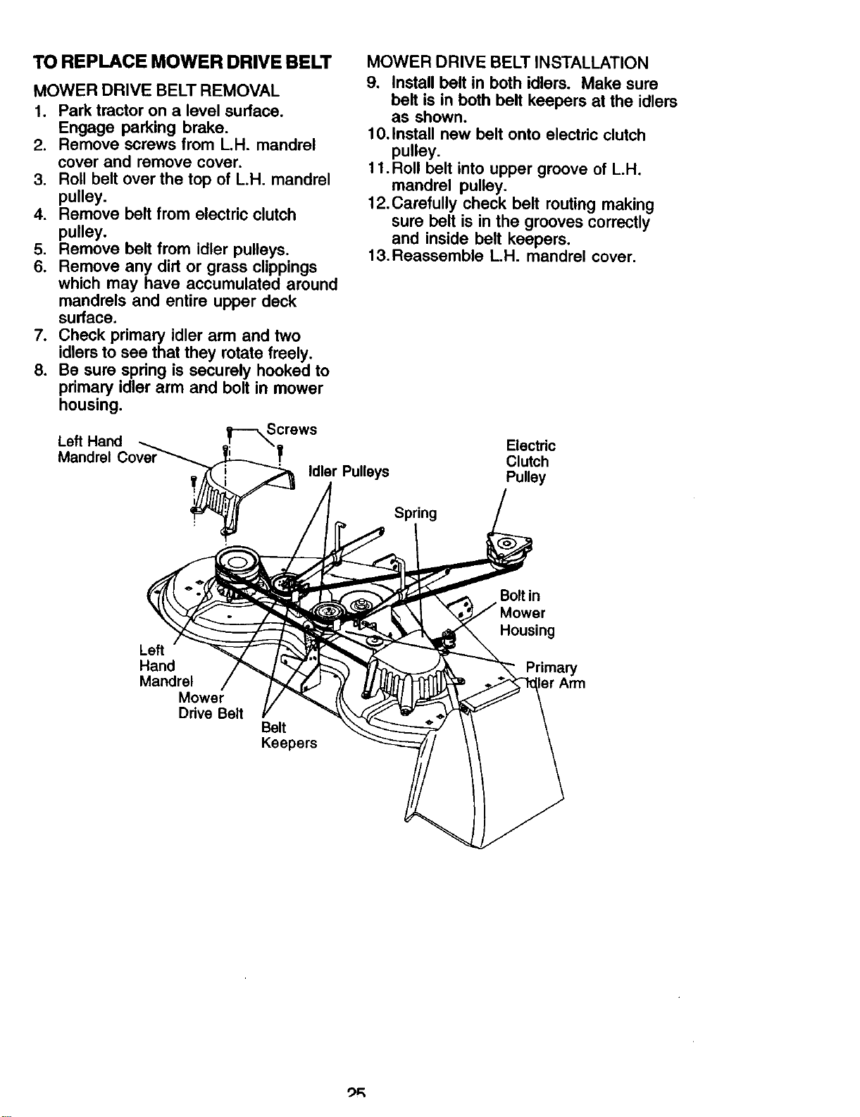
TO REPLACE MOWER DRIVE BELT
MOWER DRIVE BELT REMOVAL
1. Park tractor on a level surface.
Engage parking brake.
2. Remove screws from L.H. mandrel
cover and remove cover.
3. Roll belt over the top of L.H. mandrel
pulley.
4. Remove belt from electric clutch
pulley.
5. Remove belt from idler pulleys.
6. Remove any dirt or grass clippings
which may have accumulated around
mandrels and entire upper deck
surface.
7. Check primary idler arm and two
idlers to see that they rotate freely.
8. Be sure spring is securely hooked to
primary idler arm and bolt in mower
housing.
MOWER DRIVE BELT INSTALLATION
9. Install belt in both idlers. Make sure
belt is in both belt keepers at the idlers
as shown.
10. Install new belt onto electric clutch
pulley.
11.Roll belt into upper groove of L.H.
mandrel pulley.
12. Carefully check belt routing making
sure belt is in the grooves correctly
and inside belt keepers.
13. Reassemble L.H. mandrel cover.
Screws
Left Hand -- _ \
Mandrel Cover_ _ "T
_ Idler Pulleys
Spring
Electric
Clutch
Pulley
Left
Hand
Mandrel
Mower
Drive Belt
Belt
Keepers
Bolt in
Housing
Primary
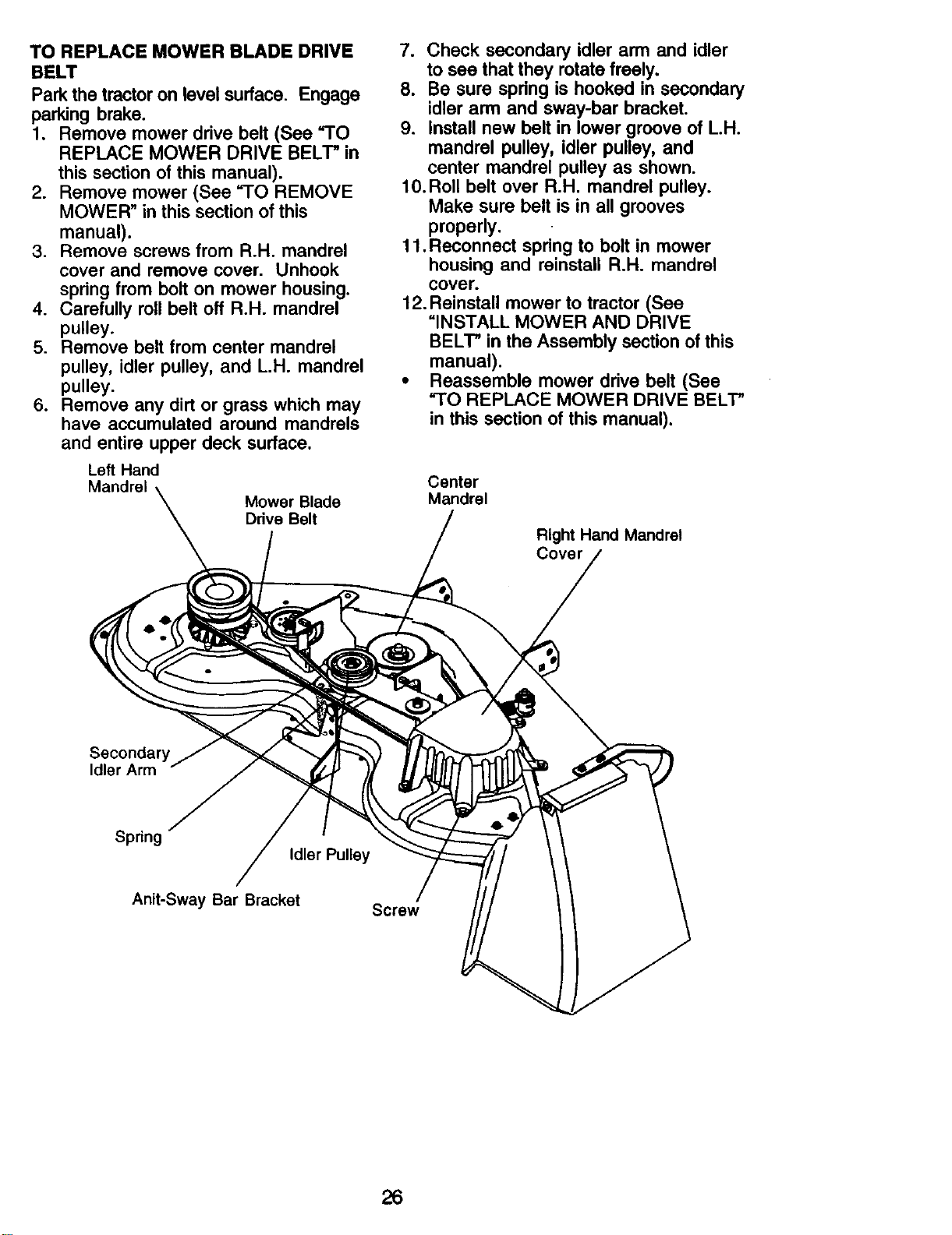
TO REPLACE MOWER BLADE DRIVE
BELT
Park the tractor on level surface. Engage
parking brake.
1. Remove mower drive belt (See "TO
REPLACE MOWER DRIVE BELT" in
this section of this manual).
2. Remove mower (See "TO REMOVE
MOWER" in this section of this
manual).
3. Remove screws from R.H. mandrel
cover and remove cover. Unhook
spring from bolt on mower housing.
4. Carefully roll belt off R.H. mandrel
pulley.
5. Remove belt from center mandrel
pulley, idler pulley, and L.H. mandrel
pulley.
6. Remove any dirt or grass which may
have accumulated around mandrels
and entire upper deck surface.
Left Hand
Mandrel
Mower Blade
Drive Belt
7. Check secondary idler arm and idler
to see that they rotate freely.
8. Be sure spdng is hooked in secondary
idler arm and sway-bar bracket.
9. Install new belt in lower groove of L.H.
mandrel pulley, idler pulley, and
center mandrel pulley as shown.
10.Roll belt over R.H. mandrel pulley.
Make sure belt is in all grooves
properly.
11. Reconnect spdng to bolt in mower
housing and reinstall R.H. mandrel
cover.
12. Reinstall mower to tractor (See
"INSTALL MOWER AND DRIVE
BELT" in the Assembly section of this
manual).
• Reassemble mower drive belt (See
"TO REPLACE MOWER DRIVE BELT"
in this section of this manual).
Center
Mandrel
Right Hand Mandrel
Cover
Secondary
Idler Arm
Spnng
Idler Pulley
Anit-Sway Bar Bracket
Screw
26
TO ADJUST ATTACHMENT CLUTCH
The electdc clutch should provide years
of service. The clutch has a built-in brake
that stops the pulley within 5 seconds.
Eventually, the internal brake will wear
which may cause the mower blades to
not engage, or, to not stop as required.
Adjustments should be made by your
nearest authorized service center/
department.
1. Make sure attachment clutch and
ignition switches are in =OFF" position.
2. Adjust the three nylon Iocknuts until
space between clutch plate and rotor
measures .012" at all three slot
locations cut in the side of brake plate.
NOTE: After installing a new electric
clutch, run tractor at full throttle and
engage and disengage electric clutch 10
cycles to wear in clutch plate.
Rotor ClutchPlate
Nylon
Locknut _> _"_, Plate
(3)
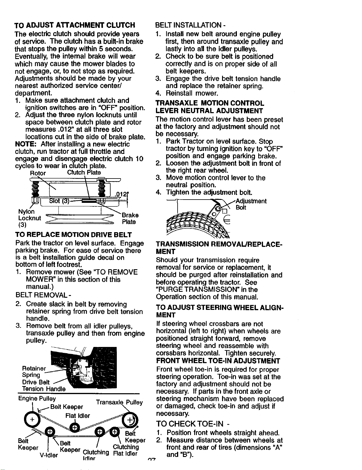
TO REPLACE MOTION DRIVE BELT
Park the tractor on level surface. Engage
parking brake. For ease of service there
is a belt installation guide decal on
bottom of left footrest.
1. Remove mower (See "TO REMOVE
MOWER" in this section of this
manual.)
BELT REMOVAL-
2. Create slack in belt by removing
retainer spring from ddve belt tension
handle.
3. Remove belt from all idler pulleys,
transaxle pulley and then from engine
pulley.
Retainer_
Spring -- _Z ,_
Drive Belt _
Tension Handle
Engine Pulley
Keeper
Transaxle Pulley
Flat ldler
Belt _Belt Keeper
Clutching
Keeper Keeper Clutching Flat Idler
V-Idler IdlAr
BELT INSTALLATION -
1. Install new belt around engine pulley
first, then around transaxle pulley and
lastly into all the idler pulleys.
2. Check to be sure belt is positioned
correctly and is on proper side of all
belt keepers.
3. Engage the drive belt tension handle
and replace the retainer spdng.
4. Reinstall mower.
TRANSAXLE MOTION CONTROL
LEVER NEUTRAL ADJUSTMENT
The motion control lever has been preset
at the factory and adjustment should not
be necessary.
1. Park Tractor on level surface. Stop
tractor by turning ignition key to "OFF"
position and engage parking brake.
2. Loosen the adjustment bolt in front of
the dght rear wheel.
3. Move motion control lever to the
neutral position.
4. Tighten the adjustment bolt.
_i _, _Adjustment
Belt
TRANSMISSION REMOVAL/REPLACE-
MENT
Should your transmission require
removal for service or replacement, it
should be purged after reinstallation and
before operating the tractor. See
"PURGE TRANSMISSION" in the
Operation section of this manual.
TO ADJUST STEERING WHEEL ALIGN-
MENT
If steering wheel crossbars are not
horizontal (left to right) when wheels are
positioned straight forward, remove
steedng wheel and reassemble with
corssbars horizontal. "l]ghten securely.
FRONT WHEEL TOE-IN ADJUSTMENT
Front wheel toe-in is required for proper
steering operation. Toe-in was set at the
factory and adjustment should not be
necessary. If parts in the front axle or
steering mechanism have been replaced
or damaged, check toe-in and adjust if
necessary.
TO CHECK TOE-IN -
1. Position front wheels straight ahead.
2. Measure distance between wheels at
front and rear of tires (dimensions "A"
and "B").
t'_'-I
• Front dimension =A"should be 1/8" to
1/4" less than rear dimension =B'.
TO ADJUST TOE-IN -
1. Loosen jam nuts at adjustment
sleeves on tie rod.
2. Adjust tie rod until dimension =A" is
1/8" to 1/4" less than dimension "B".
3. Tighten jam nuts securely.
FRONT WHEEL CAMBER
The front wheel camber is not adjustable
on your tractor. If damage has occurred to
affect the front wheel camber, contact
your nearest authorized service center/
department.
•,----_-- B-_----_
A----"---_
Adjustment Sleeves
Jam Nuts
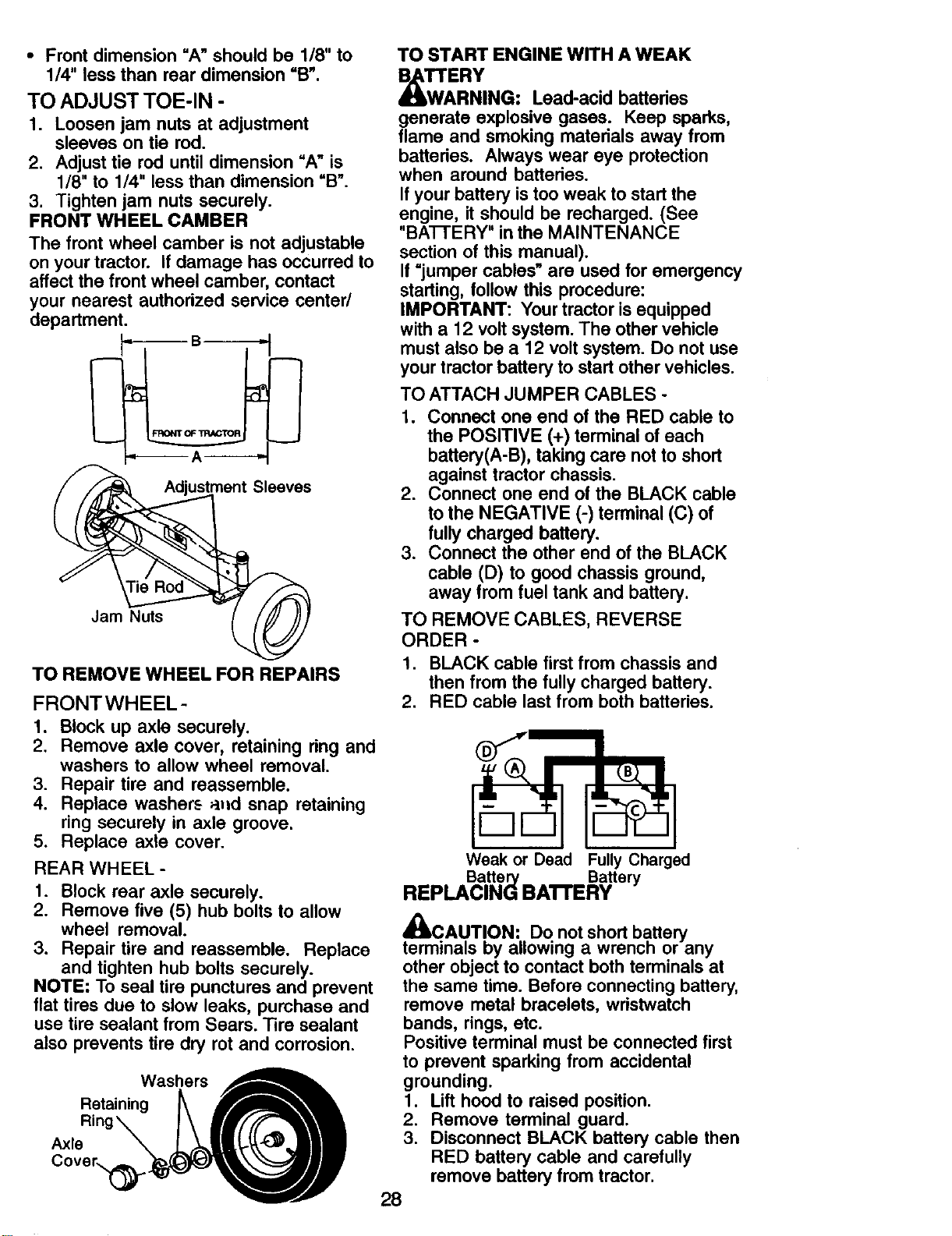
TO START ENGINE WITH A WEAK
_W'_'AERY
RNING: Lead-acid batteries
generate explosive gases. Keep sparks,
flame and smoking materials away from
batteries. Always wear eye protection
when around batteries.
If your battery is too weak to start the
engine, it should be recharged. (See
"BAI-IERY" in the MAINTENANCE
section of this manual).
If =jumper cables" are used for emergency
starting, follow this procedure:
IMPORTANT: Your tractor is equipped
with a 12 volt system. The other vehicle
must also be a 12 volt system. Do not use
your tractor battery to start other vehicles.
TO ATTACH JUMPER CABLES -
1. Connect one end of the RED cable to
the POSITIVE (+) terminal of each
battery(A-B), taking care not to short
against tractor chassis,
2. Connect one end of the BLACK cable
to the NEGATIVE (-) terminal (C) of
fully charged battery.
3. Connect the other end of the BLACK
cable (D) to good chassis ground,
away from fuel tank and battery.
TO REMOVE CABLES, REVERSE
ORDER-
TO REMOVE WHEEL FOR REPAIRS
FRONTWHEEL-
1. BLACK cable first from chassis and
then from the fully charged battery.
2. RED cable last from both batteries.
1. Block up axle securely.
2. Remove axle cover, retaining ring and
washers to allow wheel removal.
3. Repair tire and reassemble.
4. Replace washers a_ld snap retaining
ring securely in axle groove.
5. Replace axle cover.
REAR WHEEL -
1. Block rear axle securely.
2. Remove five (5) hub bolts to allow
wheel removal.
3. Repair tire and reassemble. Replace
and tighten hub bolts securely.
NOTE: To seal tire punctures and prevent
flat tires due to slow leaks, purchase and
use tire sealant from Sears. Tire sealant
also prevents tire dry rot and corrosion.
Weak or Dead Fully Charged
Batte Battery
REPLACIN_ BAI'rERY
='t
4DLCAUTION: Do not short battery
terminals by allowing a wrench or any
other object to contact both terminals at
the same time. Before connecting battery,
remove metal bracelets, wristwatch
bands, rings, etc.
Positive terminal must be connected first
to prevent sparking from accidental
Washers
Reta,n,og 1
Ring_ I\ IrlrfffZll 2.
Axle \ k *m lI 3.
grounding.
Lift hood to raised position.
Remove terminal guard.
Disconnect BLACK battery cable then
RED battery cable and carefully
remove battery from tractor.
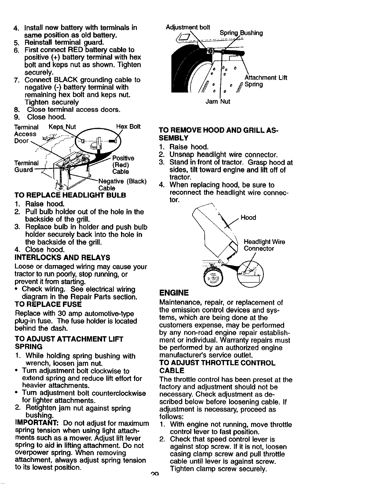
4. Install new battery with terminals in
same position as old battery.
5. Reinstall terminal guard.
6. Firstconnect RED batterycable to
positive(+) batteryterminal with hex
bolt and keps nut as shown.Tighten
securely.
7. Connect BLACK grounding cable to
negative (-) battery terminal with
remaining hex bolt and keps nut.
Tighten securely
8. Close terminal access doors.
9. Close hood.
Adjustment bolt
AttachmentLift
* /Spring
Jam Nut
Terminal KepsNut _ Hex Bolt
Access . __-:-.,,,...--__">_/" _ _X" TO REMOVE HOOD AND GRILL AS-
Door _.._.,---i _ SEMBLY
."_ ;"- i" 1. Raise hood.
." _ Positive 2. Unsnap headlight wire connector.
Terminal _ (Red) 3. Stand in front of tractor. Grasp hood at
Guard _ C:able sides, tilt toward engine and lift off of
tractor.
"_Lr j_-Negative (Black) 4. When replacing hood, be sure to
_-_" Cable
TO REPLACE HEADLIGHT BULB reconnect the headlight wire connec-
1. Raise hood.
2. Pull bulb holder out of the hole in the
backside of the grill.
3. Replace bulb in holder and push bulb
holder securely back into the hole in
the backside of the grill.
4. Close hood.
INTERLOCKS AND RELAYS
Loose or damaged widng may cause your
tractor to run poorly, stop running, or
prevent itfrom starting.
• Check wiring. See electrical wiring
diagram in the Repair Parts section.
TO REPLACE FUSE
Replace with 30 amp automotive-type
plug-in fuse. The fuse holder is located
behind the dash.
TO ADJUST ATTACHMENT LIFT
SPRING
1. While holding spring bushing with
wrench, loosen jam nut.
• Turn adjustment bolt clockwise to
extend spring and reduce lift effort for
heavier attachments.
• Turn adjustment bolt counterclockwise
for lighter attachments.
2. Retighten jam nut against spring
bushing.
IMPORTANT: Do not adjust for maximum
spring tension when using light attach-
ments such as a mower. Adjust lift lever
spring to aid in lifting attachment. Do not
overpower spring. When removing
attachment, always adjust spring tension
to its lowest position.
tot.
Hood
Headlight Wire
Connector
ENGINE
Maintenance, repair, or replacement of
the emission control devices and sys-
tems, which are being done at the
customers expense, may be performed
by any non-road engine repair establish-
ment or individual. Warranty repairs must
be performed by an authorized engine
manufacturer's service outlet.
TO ADJUST THROTTLE CONTROL
CABLE
The throttle control has been preset at the
factory and adjustment should not be
necessary. Check adjustment as de-
scribed below before loosening cable. If
adjustment is necessary, proceed as
follows:
1. With engine not running, move throttle
control lever to fast position.
2. Check that speed control lever is
against stop screw. If it is not, loosen
casing clamp screw and pull throttle
cable until lever is against screw.
Tighten clamp screw securely.
OO
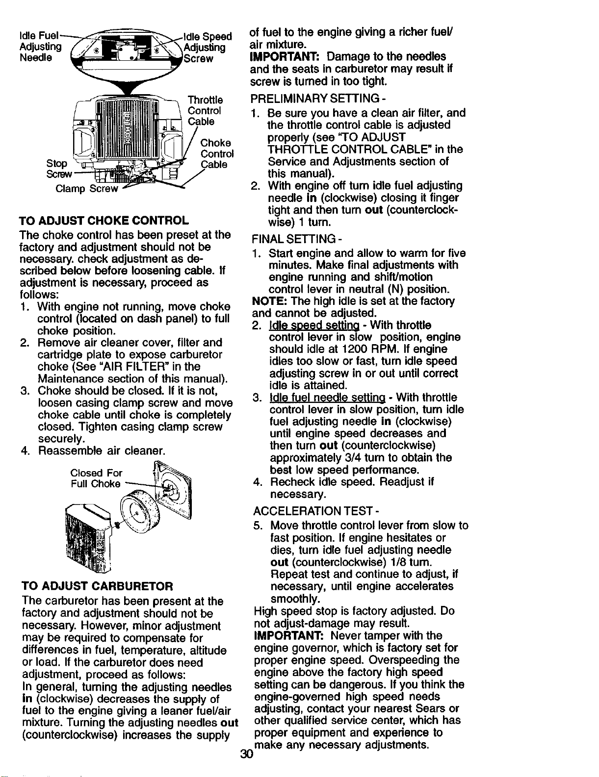
Adjusting
Needle
of fuel to the engine givinga richer fuel/
air mixture.
IMPORTANT: Damage to the needles
and the seats in carburetormay result if
screw isturned intoo tight.
Stop
Clamp Screw
Throttle
Control
Cable
Choke
Control
Cable
TO ADJUST CHOKE CONTROL
The choke control has been preset at the
factory and adjustment should not be
necessary, check adjustment as de-
scribed below before loosening cable. If
adjustment is necessary, proceed as
follows:
1. With engine not running, move choke
control (located on dash panel) to full
choke position.
2. Remove air cleaner cover, filter and
cartridge plate to expose carburetor
choke (See "AIR FILTER" in the
Maintenance section of this manual).
3. Choke should be closed. If it is not,
loosen casing clamp screw and move
choke cable until choke is completely
closed. Tighten casing clamp screw
securely.
4. Reassemble air cleaner.
Closed For
Full Choke
TO ADJUST CARBURETOR
The carburetor has been present at the
factory and adjustment should not be
necessary. However, minor adjustment
may be required to compensate for
differences in fuel, temperature, altitude
or load. If the carburetor does need
adjustment, proceed as follows:
In general, turning the adjusting needles
in (clockwise) decreases the supply of
fuel to the engine giving a leaner fuel/air
mixture. Turning the adjusting needles out
(counterclockwise) increases the supply
PRELIMINARY SETTING -
1. Be sure you have a clean air filter, and
the throttle control cable is adjusted
properly (see "TO ADJUST
THROTTLE CONTROL CABLE" in the
Service and Adjustments section of
this manual).
2. With engine off tum idle fuel adjusting
needle in (clockwise) closing it finger
tight and then turn out (counterclock-
wise) 1 turn.
FINAL SETTING -
1. Start engine and allow to warm for five
minutes. Make final adjustments with
engine running and shift]motion
control lever in neutral (N) position.
NOTE: The high idle is set at the factory
and cannot be adjusted.
2. Idle speed setting - With throttle
control lever in slow position, engine
should idle at 1200 RPM. If engine
idles too slow or fast, turn idle speed
adjusting screw in or out until correct
idle is attained.
3. Idle fuel needle setting - With throttle
control lever in slow position, tum idle
fuel adjusting needle in (clockwise)
until engine speed decreases and
then turn out (counterclockwise)
approximately 3/4 turn to obtain the
best low speed performance.
4. Recheck idle speed. Readjust if
necessary.
ACCELERATION TEST -
5. Move throttle control lever from slow to
fast position. If engine hesitates or
dies, turn idle fuel adjusting needle
out (counterclockwise) 1/8 turn.
Repeat test and continue to adjust, if
necessary, until engine accelerates
smoothly.
High speed stop is factory adjusted. Do
not adjust-damage may result.
IMPORTANT: Never tamper with the
engine governor, which is factory set for
proper engine speed. Overspeeding the
engine above the factory high speed
setting can be dangerous. If you think the
engine-governed high speed needs
adjusting, contact your nearest Sears or
other qualified service center, which has
proper equipment and experience to
make any necessary adjustments.
30
Immediately prepare your tractor for
storage at the end of the season or if the
tractor will not be used for 30 days or
more.
_CAUTION: Never store the tractor with
gasoline in the tank inside a building
where fumes may reach an open flame or
spark. Allow the engine to cool before
storing in any enclosure.
TRACTOR
Remove mower from tractor for winter
storage. When mower is to be stored for
a period of time, clean it thoroughly,
remove all dirt, grease, leaves, etc. Store
in a clean, dry area.
1. Clean entire tractor (See =CLEANING"
in the Maintenance section of this
manual).
2. Inspect and replace belts, if necessary
(See belt replacement instructions in
the Service and Adjustments section
of this manual).
3. Lubricate as shown in the Mainte-
nance section of this manual.
4. Be sure that all nuts, bolts and screws
are securely fastened. Inspect moving
parts for damage, breakage and wear.
Replace if necessary.
5. Touch up all rusted or chipped paint
surfaces; sand lightly before painting.
BATFERY
• Fully charge the battery for storage.
• After a period of time in storage, battery
may require recharging.
• To help prevent corrosion and power
leakage during long periods of storage,
battery cables should be disconnected
and battery cleaned thoroughly (see
"TO CLEAN BATTERY AND TERMI-
NALS" in the Maintenance section of
this manual).
• After cleaning, leave cables discon-
nected and place cables where they
cannot come in contact with battery
terminals.
• If battery is removed from tractor for
storage, do not store battery directly on
concrete or damp surfaces.
ENGINE
FUEL SYSTEM
IMPORTANT: It is important to prevent
gum deposits from forming in essential
fuel system parts such as carburetor, fuel
hose, or tank during storage. Also,
31
alcohol blended fuels (called gasohol or
using ethanol or methanol) can attract
moisture which leads to separation and
formation of acids during storage, Acidic
gas can damage the fuel system of an
engine while in storage.
1. Drain the fuel tank.
2. Start the engine and let it run until the
fuel lines and carburetor are empty.
• Never use engine or carburetor cleaner
products in the fuel tank or permanent
damage may occur.
• Use fresh fuel next season.
NOTE: Fuel stabilizer is an acceptable
alternative in minimizing the formation of
fuel gum deposits during storage. Add
stabilizer to gasoline in fuel tank or
storage container. Always follow the mix
ratio found on stabilizer container. Run
engine at least 10 minutes after adding
stabilizer to allow the stabilizer to reach
the carburetor. Do not drain the gas tank
and carburetor if using fuel stabilizer.
ENGINE OIL
Drain oil (with engine warm) and replace
with clean engine oil. (See =ENGINE" in
the Maintenance section of this manual).
CYLINDER(S)
1. Remove spark plug(s).
2. Pour one ounce of oil through spark
plug hole(s) into cylinder(s).
3. Turn ignition key to start position for a
few seconds to distribute oil.
4. Replace with new spark plug(s).
OTHER
• Do not store gasoline from one season
to another.
• Replace your gasoline can if your can
starts to rust. Rust and/or dirt in your
gasoline will cause problems.
• If possible, store your tractor indoors
and cover it to give protection from dust
and dirt.
• Cover your tractor with a suitable
protective cover that does not retain
moisture. Do not use plastic. Plastic
cannot breathe which allows conden-
sation to form and will cause your
tractor to rust.
IMPORTANT: Never cover tractor while
engine and exhaust areas are still warm.
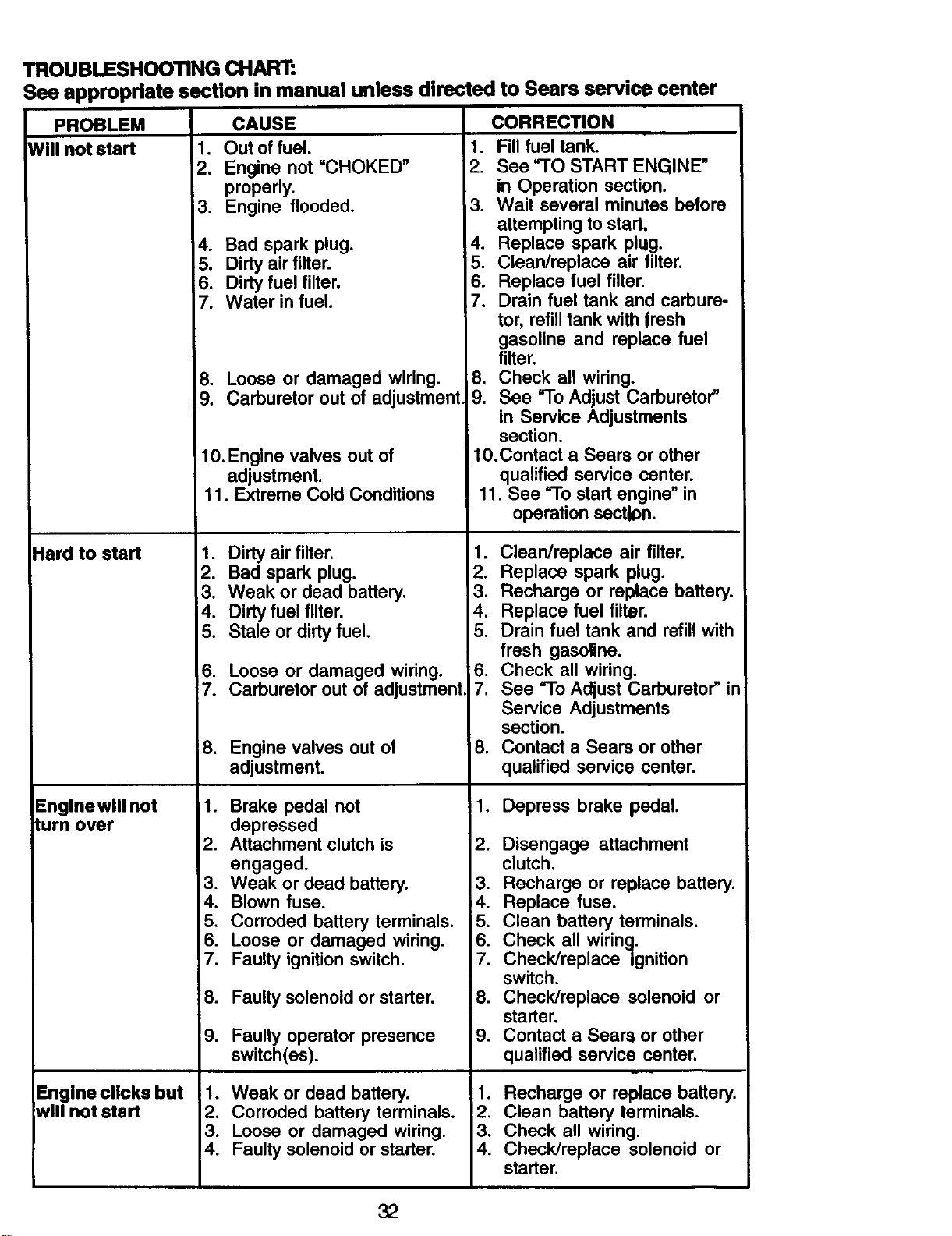
TROUBLESHOOTING CHART:
See appropriate section in manual unless directed to Sears service center
PROBLEM CAUSE CORRECTION
Will not start 1. Out of fuel.
Hard to start
Enginewill not
turn over
Engine clicks but
will not start
2. Engine not "CHOKED"
properly.
3. Engine flooded. 3.
4. Bad spark plug. 4.
5. Dirty air filter. 5.
6. Dirty fuel filter. 6.
7. Water in fuel. 7.
8. Loose or damaged wiring. 8.
9. Carburetor out of adjustment
10.Engine valves out of
adjustment.
11. Extreme Cold Conditions
1. Dirty air filter. 1.
2. Bad spark plug. 2.
3. Weak or dead battery. 3.
4. Dirty fuel filter. 4.
5. Stale or dirty fuel. 5.
Loose or damaged wiring. 6.
Carburetor out of adjustment. 7.
1. Fill fuel tank.
2. See "TO START ENGINE"
in Operation section.
Wait several minutes before
attempting to start,
Replace spark plug.
Clean/replace air filter.
Replace fuel filter.
Drain fuel tank and carbure-
tor, refill tank with fresh
gasoline and replace fuel
filter.
Check all widngo
9. See "To Adjust Carburetor"
in Service Adjustments
section.
10.Contact a Sears or other
qualified service center.
11. See "To start engine" in
operation sect_n.
Clean/replace air filter.
Replace spark plug.
Recharge or replace battery.
Replace fuel filter.
Drain fuel tank and refillwith
fresh gasoline.
Check all wiring.
See "To Adjust Carburetor"in
8. Engine valves out of
adjustment.
1. Brake pedal not
depressed
2. Attachment clutch is
engaged.
3. Weak or dead battery.
4. Blown fuse.
5.
6.
7.
,
Service Adjustments
section.
Contact a Sears or other
qualified service center.
1. Depress brake pedal.
.
3.
4.
Corroded battery terminals. 5.
Loose or damaged wiring. 6.
Faulty ignition switch. 7.
Disengage attachment
clutch.
Recharge or replace battery.
Replace fuse.
Clean battery terminals.
Check all wiring.
Check/replace Ignition
8. Faulty solenoid or starter.
9. Faulty operator presence
switch(es).
1. Weak or dead battery.
2. Corroded battery terminals.
3. Loose or damaged wiring.
4. Faulty solenoid or starter.
switch.
8. Check/replace solenoid or
starter.
=9. Contact a Sears or other
qualified service center.
1. Recharge or replace battery.
2. Clean battery terminals.
3. Check all wiring.
4. Check/replace solenoid or
starter.
32
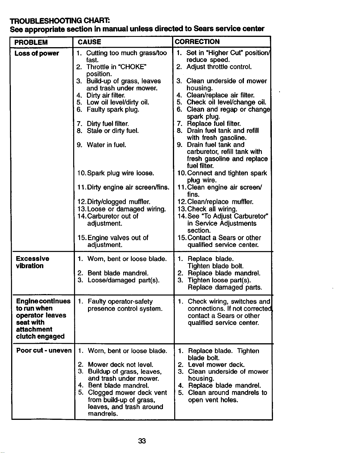
PROBLEM
Loss of power 1. Cuttingtoo much grass/too 1. Set in =Higher Cut" position/
TROUBLESHOOTING CHART:
See appropriate section in manual unless directed to Sears service center
CAUSE CORRECTION
Excessive
vibration
Enginecontinues
to run when
operator leaves
seat with
attachment
clutch engaged
Poor cut - uneven
fast.
2. Throttle in =CHOKE" 2.
position.
3. Build-up of grass, leaves 3.
and trash under mower.
4. Dirty air filter. 4.
5. Low oil level/dirty oil. 5.
6. Faulty spark plug. 6.
7. Dirty fuel filter. 7.
8. Stale or dirty fuel. 8.
9. Water in fuel. 9.
lO.Spark plug wire loose.
11 .Dirty engine air screen/fins.
12. Dirty/clogged muffler.
13.Loose or damaged wiring.
14.Carburetor out of
adjustment.
15. Engine valves out of
adjustment.
1. Worn, bent or loose blade. 1.
2. Bent blade mandrel. 2.
3. Loose/damaged part(s). 3.
1. Faulty operator-safety 1.
presence control system.
1. Worn, bent or loose blade. 1.
2. Mower deck not level. 2.
3. Buildup of grass, leaves, 3.
and trash under mower.
4. Bent blade mandrel. 4.
5. Clogged mower deck vent 5.
from build-up of grass,
leaves, and trash around
mandrels.
reduce speed.
Adjust throttle control.
Clean underside of mower
housing.
Clean/replace air filter.
Check oil level/change oil.
Clean and regap or change
spark plug.
Replace fuel filter.
Drain fuel tank and refill
with fresh gasoline.
Drain fuel tank and
carburetor, refill tank with
fresh gasoline and replace
fuel filter.
10. Connect and tighten spark
plug wire.
11 .Clean engine air screen/
fins.
12.Clean/replace muffler.
13.Check all wiring.
14, See "To Adjust Carburetor"
in Service Adjustments
section.
15. Contact a Sears or other
qualified service center.
Replace blade.
Tighten blade bolt.
Replace blade mandrel.
Tighten loose part(s).
Replace damaged parts.
Check wiring, switches and
connections. If not correctec
contact a Sears or other
qualified service center.
Replace blade. Tighten
blade bolt.
Level mower deck.
Clean underside of mower
housing.
Replace blade mandrel.
Clean around mandrels to
open vent holes.
33
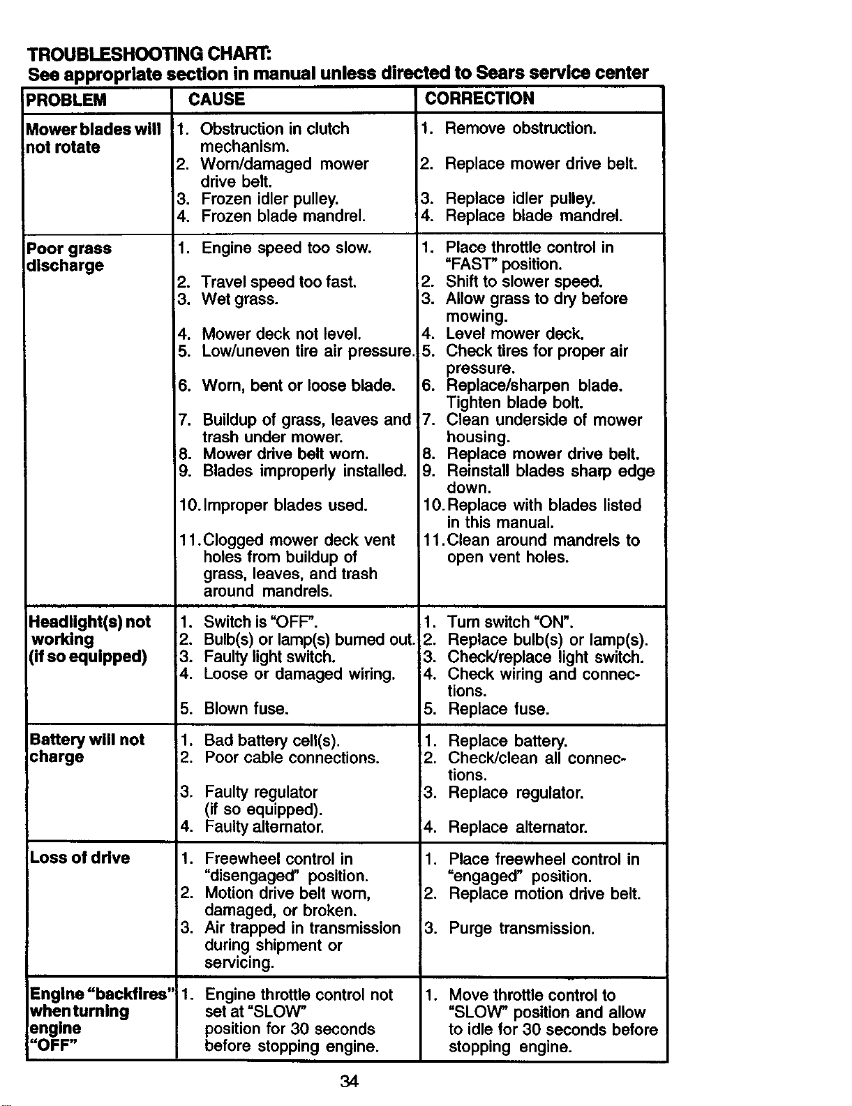
TROUBLESHOOTING CHART:
See appropriate section in manual unless directed to Sears service center
CAUSE CORRECTIONPROBLEM
Mower blades will
not rotate
Poor grass
discharge
Headlight(s) not
working
(if so equipped)
Battery will not
charge
Loss of drive
Engine "backfires"
whenturnlng
engine
"OFF"
!1. Obstruction in clutch 1. Remove obstruction.
mechanism.
2. Worn/damaged mower
drive belt.
3. Frozen idler pulley.
4. Frozen blade mandrel,
1. Engine speed too slow.
2. Travel speed too fast.
3. Wet grass.
4. Mower deck not level.
5. Low/uneven tire air pressure.
6. Wom, bent or loose blade.
7. Buildup of grass, leaves and
trash under mower.
8. Mower drive belt wom.
9. Blades improperly installed.
10. Improper blades used.
11.Clogged mower deck vent
holes from buildup of
grass, leaves, and trash
around mandrels.
1. Switch is "OFF".
2. Bulb(s) or lamp(s) bumed out.;
3. Faulty light switch.
4. Loose or damaged wiring.
5. Blown fuse.
1.
12.
!3.
.
Bad battery cell(s).
Poor cable connections.
Faulty regulator
(if so equipped).
Faulty alternator.
1. Freewheel control in
"disengaged" position.
2. Motion drive belt wom,
damaged, or broken.
3. Air trapped in transmission
during shipment or
servicing.
.
Engine throttle control not
set at "SLOW"
position for 30 seconds
before stopping engine.
2. Replace mower drive belt.
3. Replace idler pulley.
4. Replace blade mandrel.
1. Place throttle control in
"FAST" position.
2. Shift to slower speed.
3. Allow grass to dry before
mowing.
4. Level mower deck.
5. Check tires for proper air
pressure.
6. Replace/sharpen blade.
Tighten blade bolt.
7. Clean underside of mower
housing.
8. Replace mower drive belt.
9. Reinstall blades sharp edge
down.
10. Replace with blades listed
in this manual.
11.Clean around mandrels to
open vent holes.
1. Turn switch "ON".
2. Replace bulb(s) or lamp(s).
3. Check/replace light switch.
4. Check wiring and connec-
tions.
5. Replace fuse.
1. Replace battery.
2. Check/clean all connec-
tions.
3. Replace regulator.
4. Replace alternator.
1. Place freewheel control in
"engaged" position.
2. Replace motion drive belt.
3. Purge transmission.
1. Move throttle control to
"SLOW" position and allow
to idle for 30 seconds before
stopping engine.
34
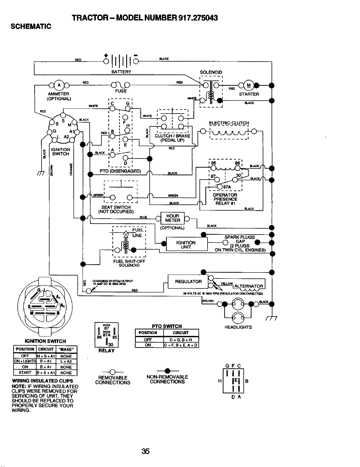
SCHEMATIC
TRACTOR- MODEL NUMBER 917.275043
RED
BATTERY SOLENOID
IGNmON SWITCH
POSmONSmONI CIRCUIT "MAKE"
O_F IM+G+ A1 NONE
ON+TOA_T B+A1 L+A2
ON B + A1 NONE
S B+S+A1 NONE
WIRING INSULATED CUPS
NOTE: IF WIRING INSULATED
CLIPS WERE REMOVED FOR
SERVICING OF UNIT, THEY
SHOULD BE REPLACED TO
PROPERLY SECURE YOUR
WIRING.
_R_NG Sy_RE_ICO'PUT _t
15/d_lP[X_0 _00 RPM
RELAY
PTO SWWCH
POS_N CIRCU_
OFF C+G,B+H
ON C+FrB+E,A+D
REGULATOR
21 VOLTS _C 0 3_0 RPM (R{,GK_ATOR D_CONN_11_O)
HEADUGHTS
REMOVABLE NON-REMOVABLE
CONNECTIONS CONNECTIONS
GFC
DA
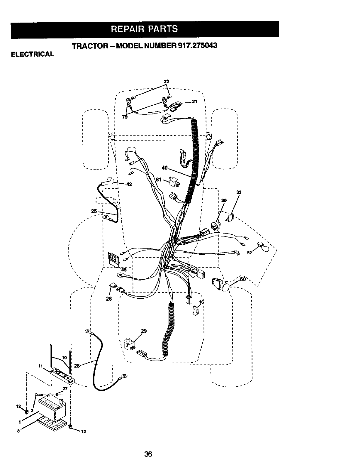
TRACTOR - MODEL NUMBER 917.275043
ELECTRICAL
22
iI
I I
I I
I I
I I
i \ L
I
• t
!
r- _r_ I
I___ \l
25 I
L
1
26
33
I
I
I
I
a6
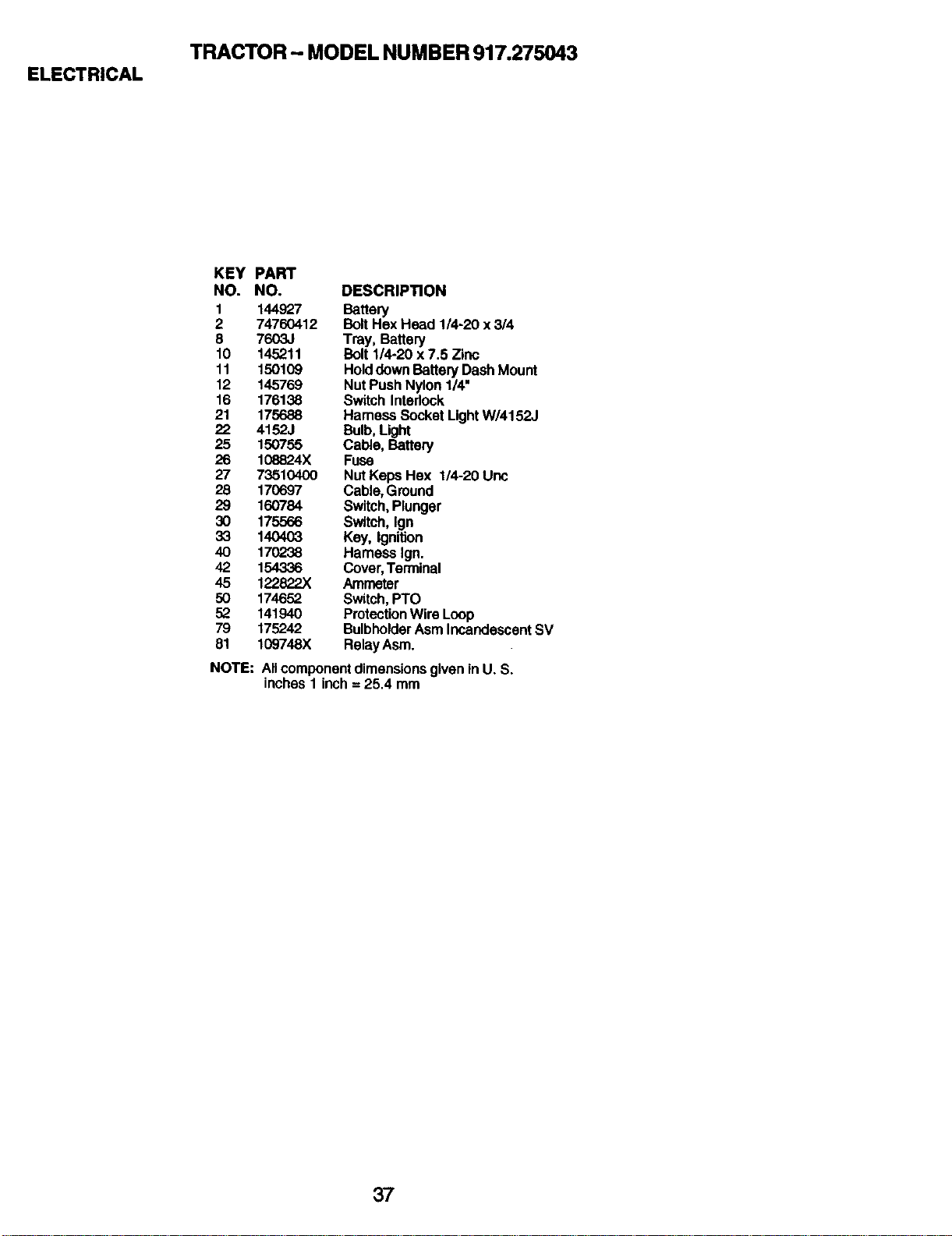
ELECTRICAL
TRACTOR - MODEL NUMBER 917.275043
KEY PART
NO. NO. DESCRIPTION
1 144927 Battery
2 74760412 Bolt Hex Head 1/4-20 x 3/4
8 7603J Tray, Battery
10 145211 Bolt 1/4-20 x 7.5 Zinc
11 150109 Hold down Battery Dash Mount
12 145769 Nut Push Nylon 1/4"
16 176138 Switch Intedock
21 175688 Hameas Socket Light W/4152J
22 4152J Bulb, Light
25 150755 Cable, Battery
26 108824X Fuse
27 73510400 Nut Keps Hex 1/4-20 Uric
28 170697 Cable, Ground
29 160784 Switch, Plunger
30 175566 Switch, Ign
33 140403 Key, Ignition
40 170238 Harness Ign.
42 154336 Cover, Terminal
45 122822X Ammeter
50 174652 Switch, PTO
52 141940 Protection Wire Loop
79 175242 Bulbholdar Asm Incandescent SV
81 109748X RalayAsm.
NOTE: All component dimensions given in U. S.
inches 1 inch = 25.4 mm
37
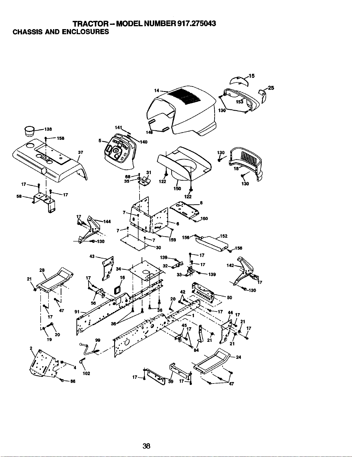
TRACTOR - MODEL NUMBER 917.275043
CHASSIS AND ENCLOSURES
138
37
28
21 17
2
102
86
38
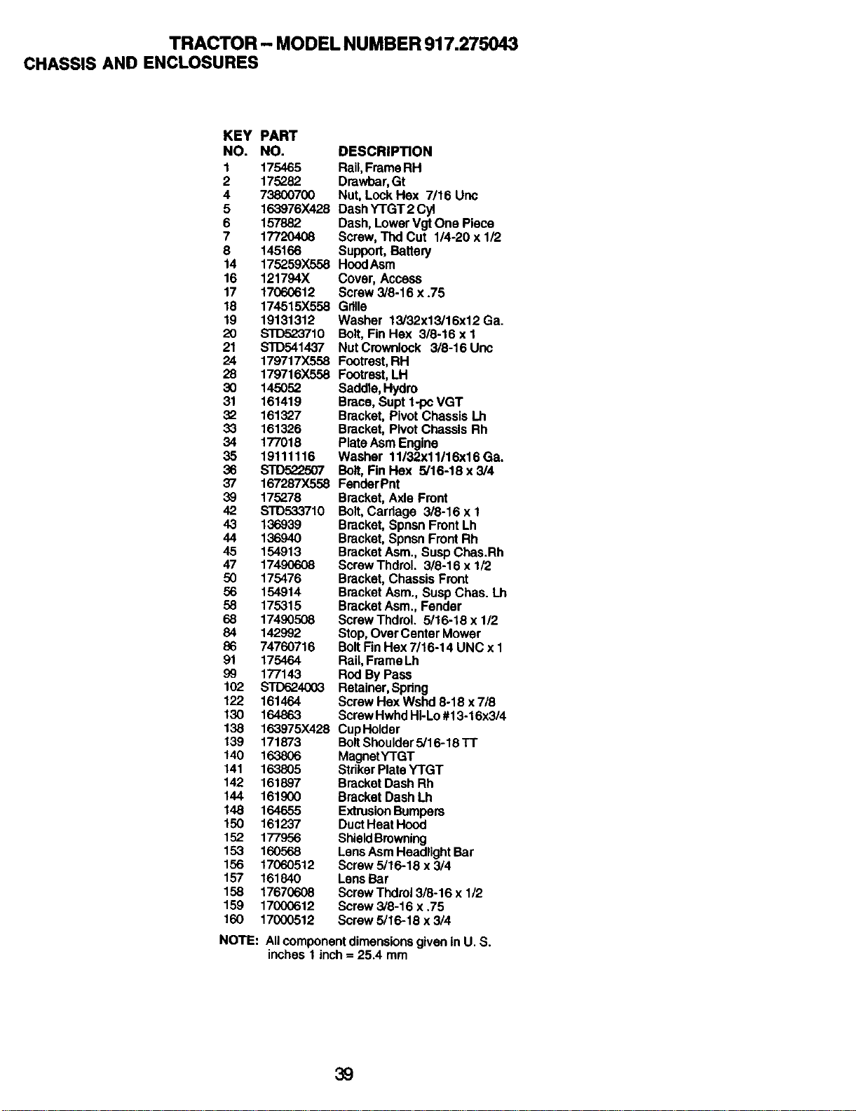
TRACTOR- MODEL NUMBER 917.275043
CHASSIS AND ENCLOSURES
KEY PART
NO. NO. DESCRIPTION
1 175465 Rail, Frame RH
2 175282 Dmwbar, Gt
4 73800700 Nut, Lock Hex 7/16 Uric
5 163976X428 Dash YTGT2 Cyl
6 157882 Dash, Lower Vgt One Piece
7 17720408 Screw, Thd Cut 1/4-20 x 1/2
8 145166 Support, Battery
14 175259X558 HoodAsm
16 121794X Cover, Access
17 17060612 Screw 3/8-16 x .75
18 174515X558 Grille
19 19131312 Washer 13/32x13/16x12 Ga.
20 STD523710 Bolt, Fin Hex 3/8-16 x 1
21 STD5414,37 Nut Crownlock 3/8-16 Uric
24 179717X558 Footrest, RH
28 179716X558 Footrest, LH
30 145052 Saddle, Hydro
31 161419 Brace, Supt 1-pc VGT
32 161327 Bracket, Pivot Chassis Lh
33 161326 Bracket, Pivot Chassis Rh
34 177018 Plate Asm Engine
35 19111116 Washer 11/32x11/16x16 Ga.
36 STDr-r_'_507 Bolt, Fin Hex 5/16-18 x 3/4
37 167287X558 FanderPnt
39 175278 Bracket, Axle Front
42 s'rD533710 Bolt, Carriage 3/8-16 x 1
43 136939 Bracket, Spnsn Front Lh
44 136940 Bracket, Spnsn Front Rh
45 154913 Bracket Asm., Susp Chas.Rh
47 17490608 Screw Thdrol. 3/8-16 x 1/2
50 175476 Bracket, Chassis Front
56 154914 Bracket Asm., Susp Chas. Lh
58 175315 Bracket Asm., Fender
68 17490508 Screw ThdroL 5/16-18 x 112
84 142992 Stop, Over Center Mower
86 74760716 Bolt Fin Hex 7/16-14 UNC x 1
91 175464 Rail, Frame Lh
99 177143 Rod By Pass
102 STD624003 Retainer, Spring
122 161464 Screw Hex Wshd 8-18 x 7/8
130 164863 Screw Hwhd HI-Lo #13-16x3/4
138 163975X428 CupHolder
139 171873 Bolt Shoulder 5/16-18 TT
140 163806 MagnetYTGT
141 163805 Striker Plata YTGT
142 161897 Bracket Dash Rh
144 161900 Bracket Dash Lh
148 164655 Extrusion Bumpers
150 161237 Duct Heat Hood
152 177956 Shield Browning
153 160568 Lens Asm Headlight Bar
156 17060512 Screw5/16-18 x 3/4
157 161840 Lens Bar
158 176706o08 Screw Thdrol 3/8-16 x 1/2
159 17000612 Screw3/8-16 x.75
160 17000512 Screw 5/16-18 x 3/4
NOTE: AllcomponentdimensionsgiveninU. S.
inches1 inch= 25.4 mm
39
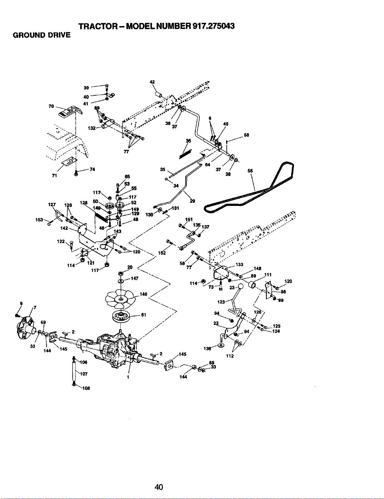
TRACTOR- MODEL NUMBER 917.275043
GROUND DRIVE
33
42
77
38 37
6
46
8
111
120
/
/
t
112
144
69
1 144
40
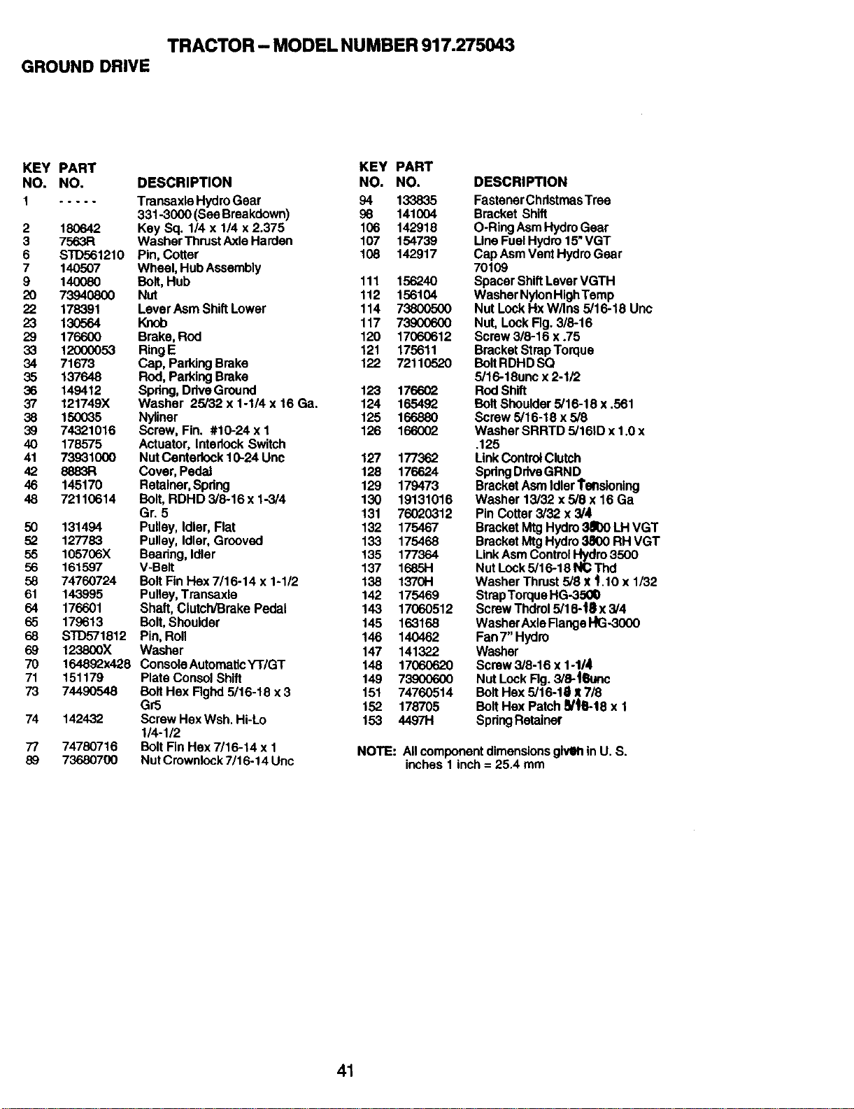
TRACTOR - MODEL NUMBER 917.275043
GROUND DRIVE
KEY PART KEY PART
NO. NO. DESCRIPTION NO. NO.
I ..... TraneaxlaHydroGear 94 133835
331-3000 (SeaBreakdown) 98 141004
2 180642 Key Sq. 1/4 x 1/4 x 2.375 106 142918
3 7563R WasherThrustAxleHarden 107 154739
6 STD561210 Pin,Cotter 108 142917
7 140507 Wheel,HubAssembly
9 140080 Bolt,Hub 111 156240
20 73940800 Nut 112 156104
22 178391 LeverAsmShiftLower 114 73800500
23 130564 Knob 117 73900600
29 176600 Brake,Rod 120 17060612
33 12000053 RingE 121 175611
34 71673 Cap,ParkingBrake 122 72110520
35 137648 Rod,ParkingBrake
36 149412 Spdng,DdveGround 123 176602
37 121749X Washer 25/32 x 1-1/4 x 16 Ga. 124 165492
38 150035 Nyliner 125 166880
39 74321016 Screw, Fin. #10-24 x I 126 166002
40 178575 Actuator,InterlockSwitch
41 73931000 NutCenterlock10-24 Unc 127 177362
42 8883R Cover,PedaJ 128 176624
46 145170 Retalner,Spdng 129 179473
48 72110614 Bolt,RDHD 3/8-16x 1-3/4 130 19131016
Gr. 5 131 76020312
50 131494 Pulley,Idlar,Flat 132 175467
52 127783 Pulley,Idler,Grooved 133 175468
55 105706X Beadng,Idler 135 177364
56 161597 V-Belt 137 16851-1
58 74760724 BoltFinHex7/16-14 x 1-1/2 138 1370H
61 143995 Pulley,Transaxle 142 175469
64 176601 Shaft,Clutch/BrakePedal 143 17060512
65 179613 Bolt, Shoulder 145 163168
68 STD571812 Pin,Roll 146 140462
69 123800X Washer 147 141322
70 164892x428 ConsolaAutomaticY'r/GT 148 17060620
71 151179 PlateCoo.solShift 149 73900600
73 74490548 Bolt Hex Rghd 5/16-18 x 3 151 74760514
Gr5 152 178705
74 142432 Screw HexWsh. Hi-Lo 153 4497H
114-1/2
77 74780716 Bolt FinHex7/16-14 x 1
89 73680700 NutCrownlock 7/16-14 Unc
DESCRIPTION
FastenerChristmasTree
BracketShift
O-Ring AsmHydroGear
LineFuelHydro15"VGT
Cap AsmVentHydroGear
70109
SpacerShiftLever VGTH
WasherNylon HighTemp
Nut LockHxW/Ins 5/16-18 Unc
Nut,LockFig.3/8-16
Screw3/8-16 x .75
BracketStrapTorque
BoltRDHDSQ
5/16-18unc x 2-1/2
ROdShift
Bolt Shoulder5/16-18 x .561
Screw5/16-18 x 5/8
WasherSRRTD 5/161Dx 1.0x
.125
LinkControl Clutch
SpringDriveGRND
BracketAsmIdlerTensioning
Washer 13/32x 5/8 x 16 Ga
Pin Cotter3/32 x 3/4
BracketMtg Hydro3_1)0LH VGT
BracketMtgHydro3800 RH VGT
LinkAsmControlI-_tdm3500
NutLock5/16-18 N_ Thd
WasherThrust5/8 x t 10x 1/32
StrapTorqueHG-350_
Screw Thdrol5/16-|8 x 3/4
WasherAxleFlangeHG-3000
Fan7"Hydro
Washer
Screw3/8-16 x 1-1/4
Nut LookRg. 3,'8-4_mc
Bolt Hex 5/16-1il X7/8
Bolt Hex Patch_/_B-18x 1
SpringRetainer
NOTE: AllcomponentdimensionsglvmtinU. S.
inches1 inch= 25.4 mm
41
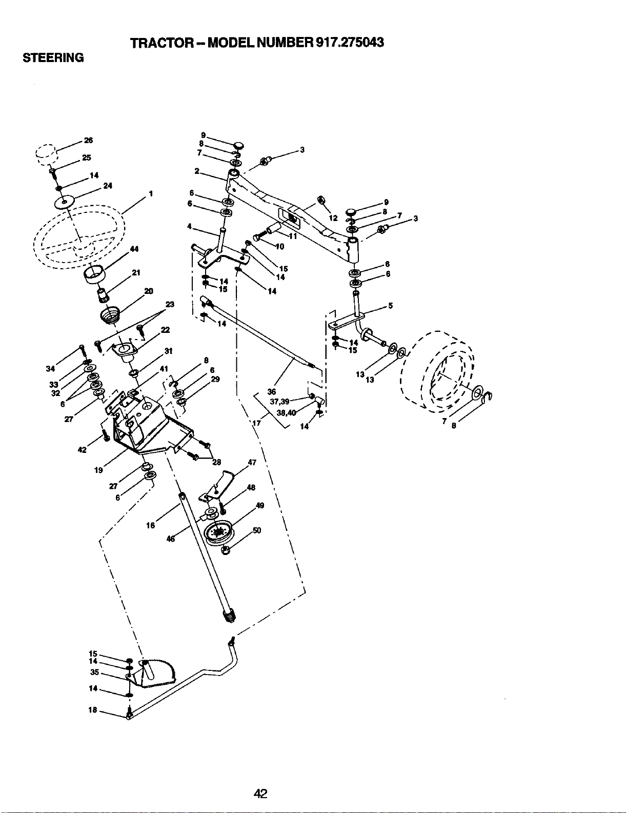
STEERING
TRACTOR - MODEL NUMBER 917.275043
23
34
33
32
27
42
22
i
i
i
19
\
\
47\
\
\
\
\
\
i
J
1313'
42
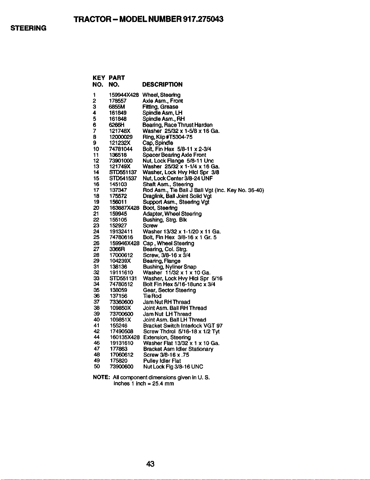
STEERING
TRACTOR - MODEL NUMBER 917.275043
KEY PART
NO. NO. DESCRIPTION
1 159944X428
2 178557
3 6855M
4 161849
5 161848
6 62661"!
7 121748X
8 12(X)0029
9 121232X
10 74781044
11 136518
12 73901000
13 121749X
14 STD551137
15 STD541537
16 145103
17 137347
18 175572
19 156011
20 163887X428
21 159945
22 155105
23 152927
24 19132411
25 74780616
26 159946X428
27 3366R
28 17000612
29 104239X
31 138136
32 19111610
33 STD551131
34 74780512
35 138059
36 137156
37 73360600
38 109850X
39 73700600
40 109851X
41 155246
42 17490508
44 160135X428
46 19131610
47 177863
48 17060612
49 175820
5O 739OO6OO
Wheel, Steering
Axle Asm., Front
Fitting, Grease
Spindle Asm, LH
Spindle Asm., RH
Beadng, RaceThrust Harden
Washer 25/32 x 1-5/8 x 16 Ga.
Ring, Kiip#T5304-75
Cap, Spindle
Bolt, Fin Hax 5/8-11 x 2-3/4
Spacer Bearing Axle Front
Nut, Lock Flange 5/8-11 Unc
Washer 25/32 x 1-1/4 x 16 Ga.
Washer, Lock Hvy Hlcl Spr 3/8
Nut, Lock Canter 3/8-24 UNF
Shaft Asm., Steering
Rod Asm., Tie Ball J Ball Vgt (Inc. Key No. 36-40)
Draglink, Ball Joint Solid Vgt
Support Asm., Steadng Vgt
Boot, Stearlng
Adapter, Wheel Steering
Bushing, Strg. BIk
Screw
Washer 13/32 x 1-1/20 x 11 Ga.
Bolt, Fin Hax 3/8-16 x 1 Gr. 5
Cap, Wheel Steadng
Beadng, Col. Strg.
Screw, 3/8-16 x 3/4
Bearing, Flange
Bushing, Nyliner Snap
Washer 11/32 x 1 x 10 Ga.
Washer, Lock Hvy Hlcl Spr 5/16
Bolt Fin Hex 5/16-18unc x 3/4
Gear, Sector Steadng
Tie Rod
Jam Nut RH Thread
Joint Asm. Ball RH Thread
Jam Nut LH Thread
Joint Asm. Ball LH Thread
Bracket Switch Interlock VGT 97
Screw Thdrol 5/16-18 x 1/2 Tyt
Extension, Steadng
Washer Flat 13/32 x 1 x 10 Ga.
Bracket Asm Idler Stationary
Screw 3/8-16 x .75
Pulley Idler Flat
Nut Lock Fig 3/8-16 UNC
NOTE: All component dimensions given In U. S.
inches 1 inch = 25.4 mm
43
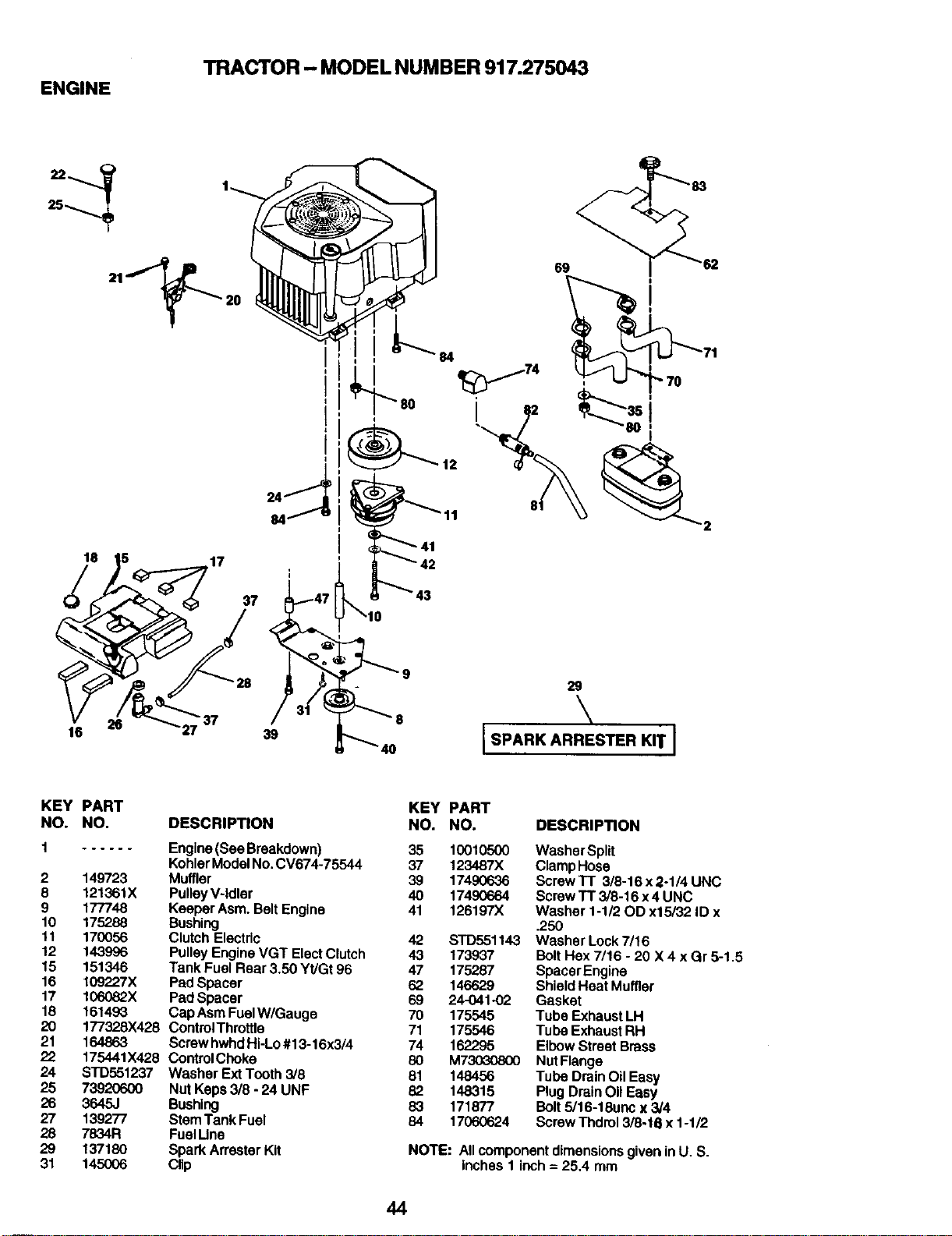
ENGINE
TRACTOR - MODEL NUMBER 917.275043
25
18
16
17
37
39
84
80 i
29
\
ISpA.KA.R S .KITI
KEY
NO.
2
8
9
10
11
12
15
16
17
18
2O
21
22
24
25
26
27
28
29
31
PART
NO. DESCRIPTION
...... Engine (Bee Breakdown)
Kohler Model No. CV674-75544
149723 Muffler
121361X Pu|ley V-|d|er
177748 Keeper Asm. Belt Engine
175288 Bushing
170056 Clutch Electdc
143996 Pulley Engine VGT Elect Clutch
151346 Tank Fuel Rear 3.50 Yt/Gt 96
109227X Pad Spacer
106082X Pad Spacer
161493 Cap Asm FuelW/Gauge
177328X428 ControlThrotUe
164863 Screw hwhd Hi-Lo #13-16x3/4
175441X428 ControlChoke
STD551237 Washer Ext Tooth 3/8
73920600 Nut Keps 3/8 - 24 UNF
3645J Bushing
139277 Stem Tank Fuel
7834R Fuel I.Jne
137180 Spark An'ester Kit
145006 Clip
KEY PART
NO. NO. DESCRIPTION
35 10010500 Washer Split
37 123487X Clamp Hose
39 17490636 Screw TT 3/8-16 x 2-1/4 UNC
40 17490664 Screw TT 3/8-16 x 4 UNC
41 126197X Washer 1-112 OD x15/32 ID x
.250
42 STD551143 Washer Lock 7/16
43 173937 Bolt Hex 7/16 - 20 X 4 x Gr 5-1.5
47 175287 Spacer Engine
62 146629 Shield Heat Muffler
69 24-041-02 Gasket
70 175545 Tube Exhaust LH
71 175546 Tube Exhaust RH
74 162295 Elbow Street Brass
80 M73030800 Nut Flange
81 148456 Tube Drain Oil Easy
82 148315 Plug Drain OII Easy
83 171877 Bolt 5/16-18un0 x 3/4
84 17060624 Screw Thdml 3/8-16 x 1-1/2
NOTE: All component dimensions given in U. S.
Inches 1 inch = 25,4 mm
44
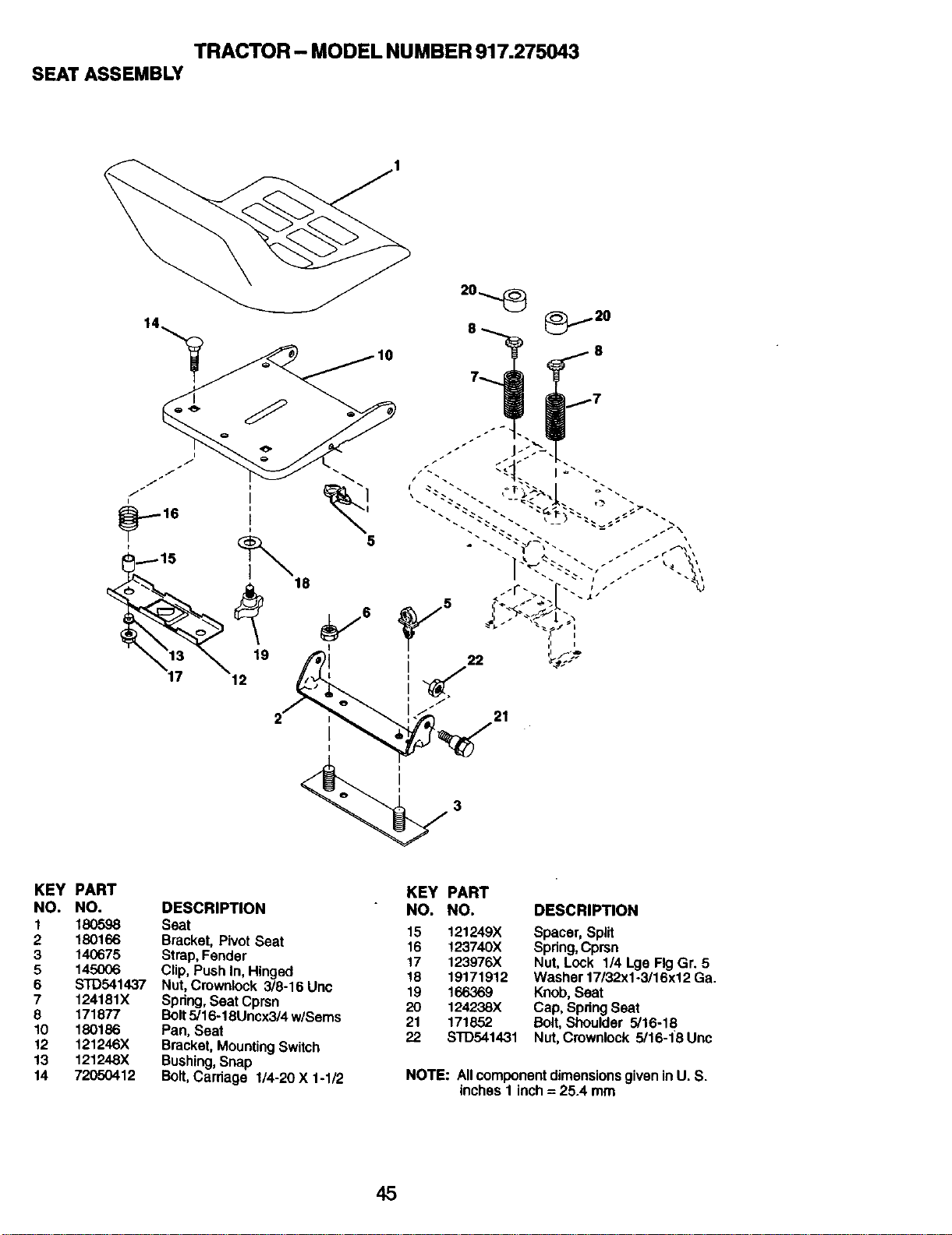
TRACTOR - MODEL NUMBER 917.275043
SEAT ASSEMBLY
12
21
KEY
NO,
I
2
3
5
6
7
8
1o
12
13
14
PART
NO.
18O598
180166
140675
145006
STD541437
124181X
171877
180186
121246X
121248X
72050412
DESCRIPTION
Seat
Bracket,PivotSeat
Strap,Fender
Clip,PushIn,Hinged
Nut,Crownlock3/8-16 Unc
Spdng,Seat Cprsn
Bolt5/16-18Uncx3/4w/Sems
Pan, Seat
Bracket,MountingSwitch
Bushing,Snap
Bolt, Carriage 1/4-20X 1-1/2
KEY PART
NO. NO. DESCRIPTION
15 121249X Spacer, Spilt
16 !23740X Spring, Cprsn
17 123976X Nut, Lock 1/4 Lge Fig Gr. 5
18 19171912 Washer 17/32x1-3/16x12 Ga.
19 166369 Knob, Seat
20 124238X Cap, Spring Seat
21 171852 Bolt, Shoulder 5/16-18
22 S'FD541431 Nut, Cmwnlock 5/16-18 Unc
NOTE: Allcomponentdimensionsgivenin U. S.
inchesI inch= 25.4 mm
45
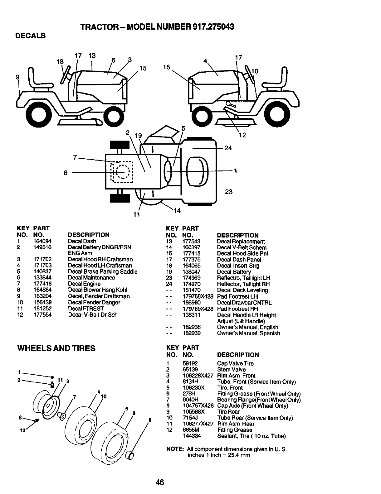
DECALS
TRACTOR- MODEL NUMBER 917.275043
9
18
17 13
3
15 15
17
I0
KEY PART
NO. NO.
1 164094
2 149516
3 171702
4 171703
5 140837
6 133644
7 177416
8 164884
9 163204
10 156439
11 181252
12 177554
8
12
-- 24
-- 23
KEY PART
DESCRIPTION NO. NO.
DecalDash 13 177543
DecalBatteryDNGP,/PSN 14 160397
ENGAsm 15 177415
DecaIHood RHCraftsman 17 177375
Decal HoodLHCraftsman 18 164065
DecalBrakeParkingSaddle 19 138047
DecalMaintenance 23 174969
DecalEngine 24 174970
DecalBlowerHsngKohl - - 181470
Decal,FenderCraftsman - - 179768X428
DecalFenderDanger - - 166960
DecalFTREST - - 179769X428
DecalV-BeltDr Sch - - 138311
. - 182938
- - 182939
WHEELSAND RES
7
3
4
10
5
9
a
DESCRIPTION
DecalReplacement
DecaIV-BeltSchem
DecalHoodSidePnl
DecalDashPanel
Decal InsertStrg
DecalBattery
Refiectro,TaillightLH
Reflector,TailightRH
Decal Deck Leveling
Pad FootrestLH
DecalDrawbarCNTRL
PadFootrestRH
DecalHandleLftHeight
Adjust(LiftHandle)
Owner'sManual,English
Owner'sManual,Spanish
KEY PART
NO. NO. DESCRIPTION
1 59192 Cap Valve Tire
2 65139 Stem Valve
3 106228)(.427 Rim Asm Front
4 8134H Tube, Front (Service Item Only)
5 106230X Tire, Front
6 278H Fitting Grease (Front Whee| Only)
7 9040H Beadng Flange(Front Wheel Only)
8 104757)(428 Cap Axle (Front Wheel Only)
9 105588X Tire Rear
10 7154J Tube Rear (Service Item Only)
11 106277X427 RimAsm Rear
12 6856M FittingGrease
- - 144334 Sealant, Tire ( 10 oz. Tube)
NOTE: A11componentdimensions g|ven in U. S.
inches1 inch= 25.4 mm
46
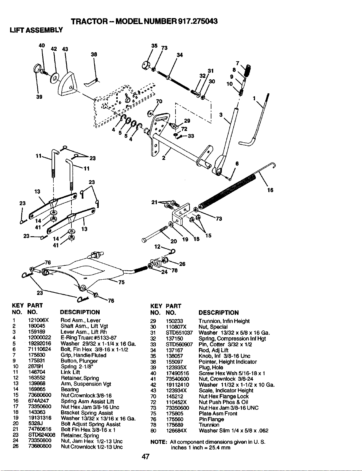
TRACTOR - MODEL NUMBER 917.275043
LIFT ASSEMBLY
4O
39
42 43
38
36 73
7
8
9
_.. 10
• 1
I \
29 _
4 72
20 19 16
15
16
75
KEY PART
NO. NO. DESCRIPTION
I 121006X Rod Asm., Lever
2 180045 Shaft Asm., Lift Vgt
3 159189 Lever Asm., Lift Rh
4 12000022 E-RingTruarc #5133-87
5 19292016 Washer 29/32 x 1-1/4 x 16 Ga.
6 71110624 Bolt, Fin Hex 3/8-16 x 1-1/2
7 175830 Grip, Handle Fluted
9 175831 Button, Plunger
10 2676H Spring 2-1/8"
11 146704 Link Lift
12 163.552 Retainer, Spring
13 139868 Arm, Suspension Vgt
14 169865 Bearing
15 73680600 Nut Crownlock 3/8-16
16 674A247 Spdng Asm Assist Lift
17 73350600 Nut Hex Jam 3/8-16 Unc
18 143363 Bracket Spring Assist
19 19131316 Washer 13/32 x 13/16 x 16 Ga.
20 5328J Bolt Adjust Spdng Assist
21 74760616 Bolt Fin Hex 3/8-16 x 1
23 STD624008 Retainer, Spring
24 73350800 Nut, Jam Hex 1/2-13 Unc
26 73680800 NutCmwnlock 1/2-13 Unc
KEY PART
NO. NO.
29 150233
30 110807X
31 s"rD551037
32 137150
33 STD560907
34 137167
35 138057
38 155097
39 123935X
40 17490516
41 73540600
42 19112410
43 123934X
70 145212
72 110452X
73 73350600
75 175805
76 175560
78 175689
80 126684X
DESCRIPTION
Trunnion, Infin Height
Nut, Special
Washer 13/32 x 5/8 x 16 Ga.
Spring, Compression Inf Hgt
Pin, Cotter 3/32 x 1/2
Rod, Adj Lift
Knob, Inf 3/8-16 Uric
Pointer, Height Indicator
Plug, Hole
Screw Hex Wsh 5/16-18 x 1
Nut, Crownlock 3/8-24
Washer 11/32 x 1-1/2 x 10 Ga.
Scale, Indicator Height
Nut Hex Flange Lock
Nut Push Phos & Oil
Nut Hex Jam 3/8-16 UNC
Plate Asm Front
Pin Flange
Trunnion
Washer Slim 1/4 x 5/8 x .062
NOTE: All component dimensions given in U. S.
inches I inch = 25.4 mm
47
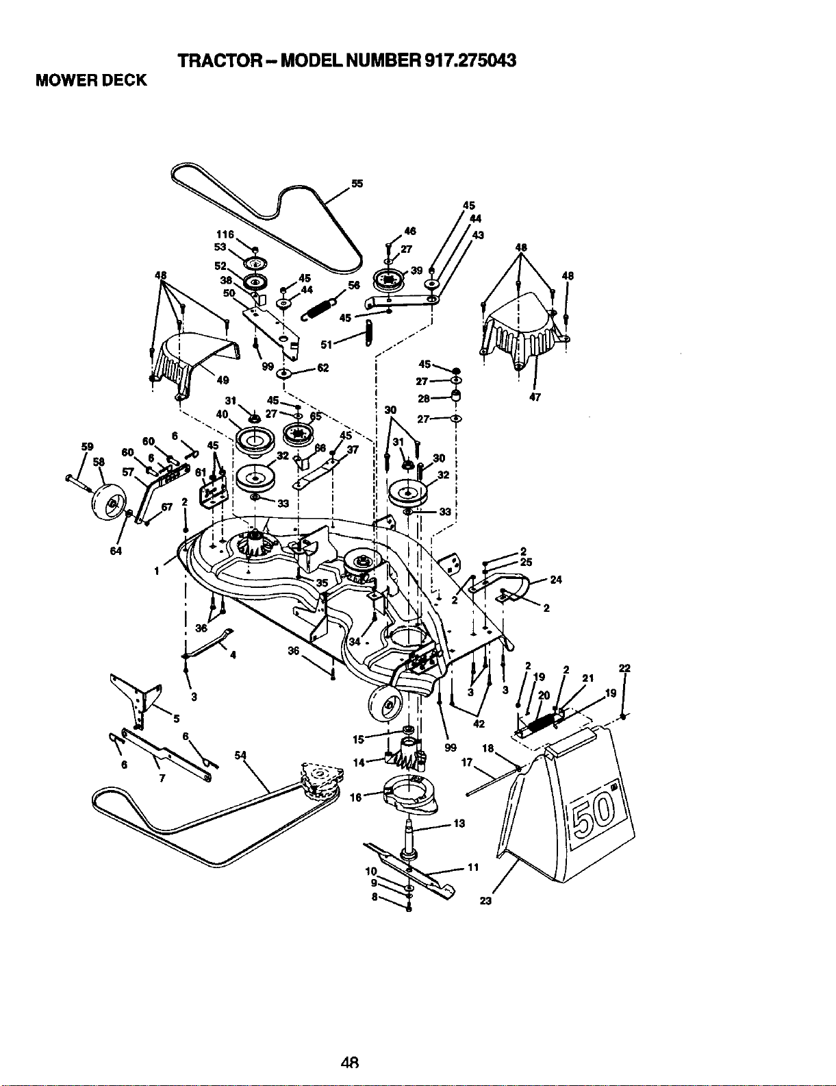
MOWER DECK
TRACTOR - MODEL NUMBER 917.275043
55
45
44
59
99\
48
47
64
2
36
2 2 22
21
6
99
23
dR
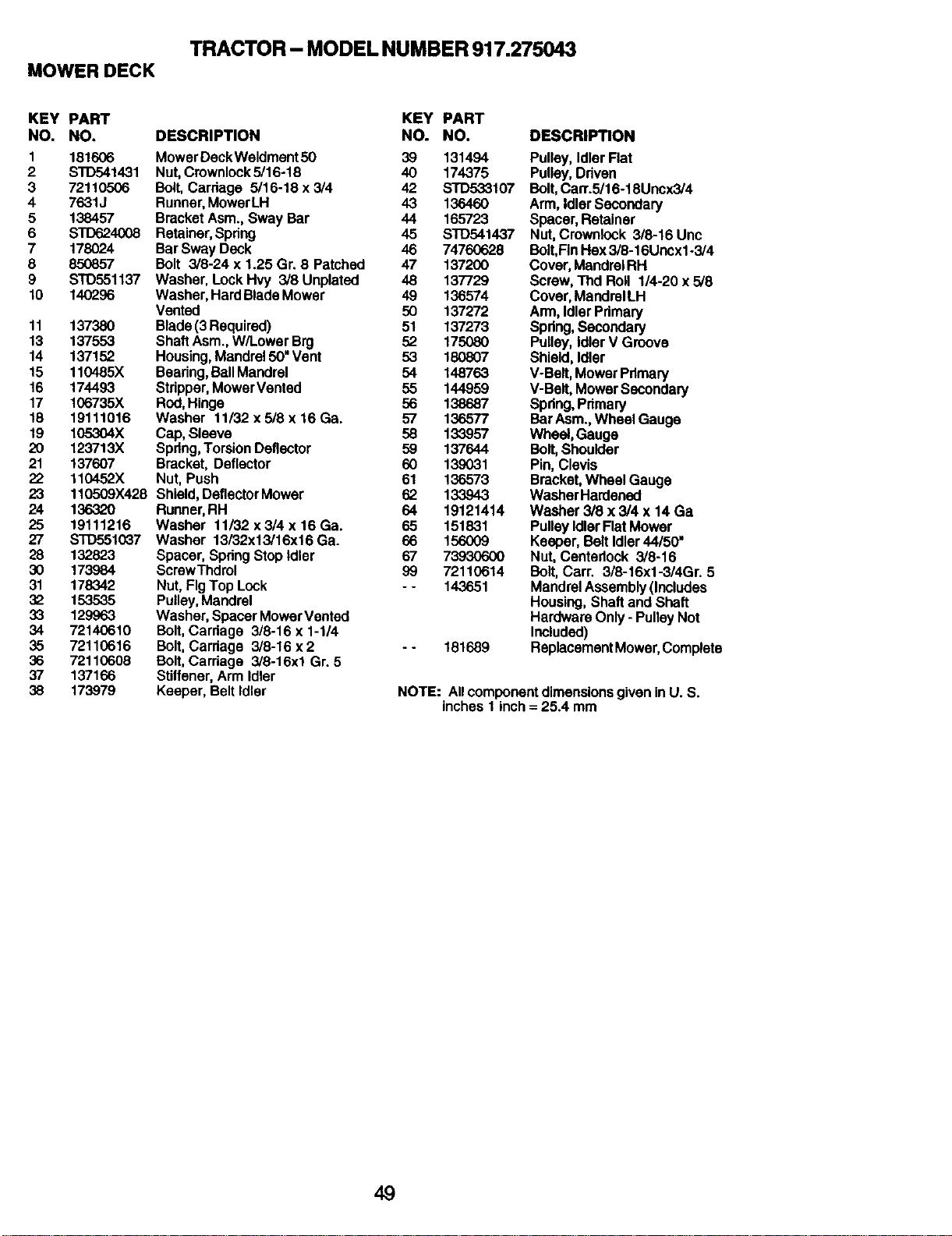
MOWERDECK
TRACTOR - MODEL NUMBER 917.275043
KEY PART
NO. NO.
1 181606
2 STD541431
3 72110506
4 7631J
5 138457
6 STD624008
7 178024
8 850857
9 STD551137
10 140296
11 137380
13 137553
14 137152
15 110485X
16 174493
17 106735X
18 19111016
19 105,,-.-.-.-.-.-.-.-__ X
20 123713X
21 137607
22 110452X
23 110ro09X428
24 13632O
25 19111216
27 8TD551037
28 132823
30 173984
31 178342
32 153535
33 129963
34 72140610
35 72110616
36 72110608
37 137166
38 173979
DESCRIPTION
KEY PART
NO. NO.
MowerDeckWeldment50 39 131494
Nut,Crownlock5/16-18 40 174375
Bolt,Carriage 5/16-18x3/4 42 STD533107
Runner,MowerLH 43 136460
BracketAsm.,Sway Bar 44 165723
Retainer,Spdng 45 STD541437
BarSwayDeck 46 74760628
Bolt 3/8-24 x 1.25 Gr. 8 Patched 47 137200
Washer, LockHvy 3/8 Unplated 48 137729
Washer,HardBlade Mower 49 136574
Vented 50 137272
Blade(3 Required) 51 137273
ShaftAsm.,W/LowerBrg 52 175080
Housing,Mandrel50"Vent 53 180807
Bearing,BallMandrel 54 148763
Stripper,MowerVented 55 144959
Rnd,Hinge 56 138687
Washer 11/32 x 5/8 x 16 Ga. 57 136577
Cap,Sleeve 58 133957
Spring,TorsionDeflector 59 137644
Bracket,Deflector 60 139031
Nut,Push 61 136573
Shield,DeflectorMower 62 133943
Runner,RH 64 19121414
Washer 11/32 x 3/4 x 16 Ga. 65 151831
Washer 13/32x13/16x16 Ga. 66 156009
Spacer,SpringStopIdler 67 73930600
ScrewThdrol 99 72110614
Nut,FigTop Lock - - 143651
Pulley,Mandrel
Washer,SpacerMowerVented
Bolt,Carriage 3/8-16 x 1-1/4
Bolt,Carriage 3/8-16 x 2 - - 181689
Bolt, Cardage 3/8-16xl Gr.5
Stiffener,Arm Idler
Keeper, BeltIdler
DESCRIPTION
Pulley, IdlerFlat
Pulley,Driven
Bolt, Cart.5/16-18Uncx3/4
Arm,Idler Secondary
Spacer, Retainer
Nut,Crownlock 3/8-16 Unc
Bolt,Fin Hex 3/8-16Uncx1-3/4
Cover, MandrelRH
Screw, Thd Roll 1/4-20 x 5/8
Cover, MandrelLH
Arm,Idler Primary
Spdng, Secondary
Pulley, Idler V Groove
Shield, Idler
V-Belt, MowerPrimary
V-Belt, Mower Secondary
Spdng, Primary
Bar Asm.,Wheel Gauge
Wheel, Gauge
Bolt,Shoulder
Pin, Clevis
Bracket, Wheel Gauge
Washer Hardened
Washer 3/8 x 3/4 x 14Ga
Pulley IdlerFlatMower
Keeper, BeltIdler 44/50"
Nut, Centedock 3/8-18
Bolt, Carr. 3/8-16x1-3/4Gr. 5
Mandrel Assembly (Includes
Housing, Shaft and Shaft
Hardware Only - Pulley Not
Included)
ReplacementMower,Complete
NOTE: All component dimensions given in U. S.
inches 1 inch = 25.4 mm
49
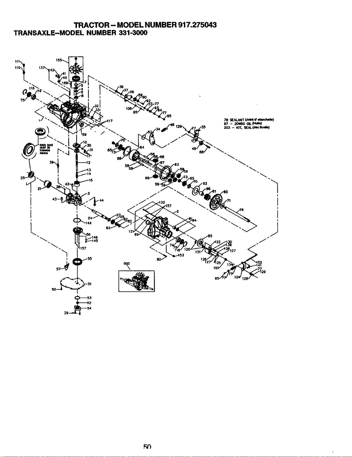
TRACTOR- MODEL NUMBER 917.275043
TRANSAXLE-MODEL NUMBER 331-3000
I
12
F,N
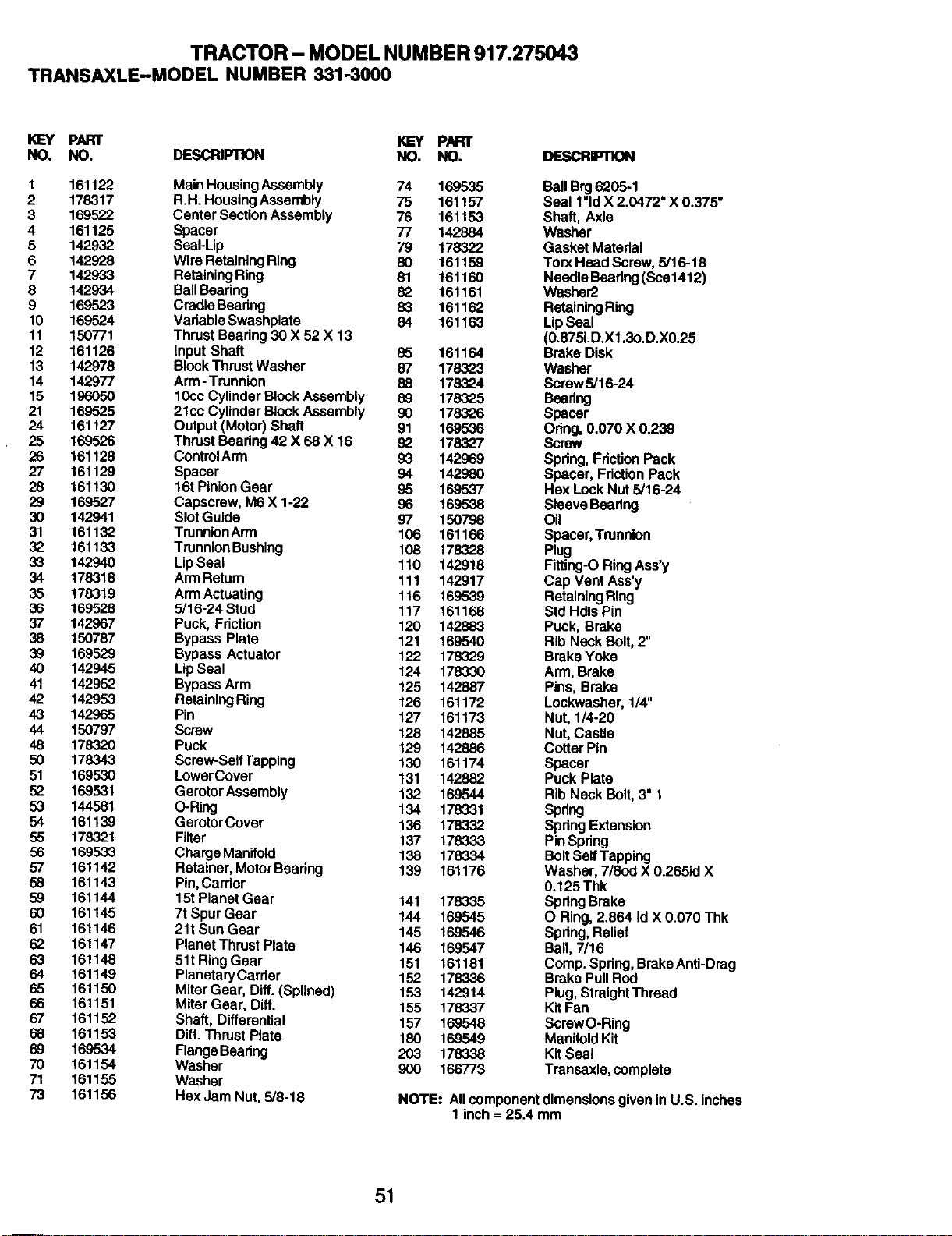
TRACTOR- MODEL NUMBER 917.275043
TRANSAXLE-MODEL NUMBER 331-3000
KEY PART KEY PART
NO. NO. DESCRIPTION NO. NO.
1 161122 Main Housing Assembly 74 169535
2 178317 R.H. Housing Assembly 75 161157
3 169522 Center Section Assembly 76 161153
4 161125 Spacer 77 142884
5 142932 Seal-Lip 79 178322
6 142928 Wire Retaining Ring 80 161159
7 142933 Retaining Ring 81 161160
8 142934 Ball Bearing 82 161161
9 169523 Cradle Beadng 83 161162
10 169524 Vadable Swashplate 84 161163
11 150771 Thrust Beadng 30 X 52 X 13
12 161126 Input Shaft 85 161164
13 142978 Block Thrust Washer 87 178323
14 142977 Arm-Trunnion 88 178324
15 196050 10cc Cylinder Block Assembly 89 178325
21 169525 21cc Cylinder Block Assembly 90 178326
24 161127 Output (Motor) Shaft 91 169536
25 169526 Thrust Bearing 42 X 68 X 16 92 178327
26 161128 ControlArm 93 142969
27 161129 Spacer 94 142980
28 161130 16t Pinion Gear 95 169537
29 169527 Capscrew, M6 X 1-22 96 169538
30 142941 Slot Guide 97 150798
31 161132 TrunnionArm 106 161166
32 161133 Trunnion Bushing 108 178328
33 142940 Lip Seal 110 142918
34 178318 Arm Retum 111 142917
35 178319 Arm Actuating 116 169539
36 169528 5/16-24 Stud 117 161168
37 142967 Puck, Friction 120 142883
38 150787 Bypass Plate 121 169540
39 169529 Bypass Actuator 122 178329
40 142945 Lip Seal 124 178330
41 142952 Bypass Arm 125 142887
42 142953 Retaining Ring 126 161172
43 142965 Pin 127 161173
44 150797 Screw 128 142885
48 178320 Puck 129 142886
50 178343 Screw-Self Tapping 130 161174
51 169530 LowerCover 131 142882
52 169531 Gemtor Assembly 132 169544
53 144581 O-Ring 134 178331
54 161139 GerotorCover 136 178332
55 178321 Filter 137 178333
56 169533 Charge Manifold 138 178334
57 161142 Retainer, Motor Beadng 139 161176
58 161143 Pin,Carrier
59 161144 15t Planet Gear 141 178335
60 161145 7tSpurGear 144 169545
61 161146 21t SunGear 145 169546
62 161147 Planet Thrust Plate 146 169547
63 161148 51t Ring Gear 151 161181
64 161149 PlanetaryCarder 152 178336
65 161150 MitarGear, Diff. (Spllned) 153 142914
66 161151 MitarGear, Diff. 155 178337
67 161152 Shaft, Differential 157 169548
68 161153 Diff. Thrust Plate 180 169549
69 169534 Flange Beadng 203 178338
70 161154 Washer 900 166773
71 161155 Washer
73 161156 Hex Jam Nut, 5/8-18
BollBrg6206-1
Seal l"ld X 2.0472" X 0.375"
Shaft, Axle
Washer
GasketMatedal
Ton(HeadScrew,5/16-18
NeedleBearing(SCO1412)
Washer2
RetainingRing
LipSeal
(0.875LD.X1.3o.D.X0.25
Brake Disk
Washer
Screw5/16-24
Bearing
Spacer
Odng, 0.070 X 0.239
Screw
Spdng,FrictionPack
Spacer, FdctionPack
HexLockNut 5/16-24
SleeveBeadng
Oil
Spacer,Trunnion
Plug
Fiffing-ORingAss'y
Cap VentAss'y
RetainingRing
StdHdlsPin
Puck, Brake
RibNeckBolt,2"
BrakeYoke
Arm,Brake
Pins,Brake
Lockwasher,1/4"
Nut,1/4-20
Nut,Castle
CofferPin
Spacer
PuckPlate
RibNeckBolt,3" 1
Spnng
SpringExtension
PinSpring
BoltSelfTapping
Washer,7/8od X 0.2651dX
0.125Thk
SpringBrake
O Ring,2.864 Id X 0.070 Thk
Spring,Relief
Ball,7/16
Comp.Spdng,BrakeAnti-Drag
BrakePullRod
Plug,StraightThread
KitFan
ScrewO-Ring
ManifoldKit
KitSeal
Transaxle,complete
NOTE: All component dimensions given in U.S. inches
1 inch = 25,4 mm
51
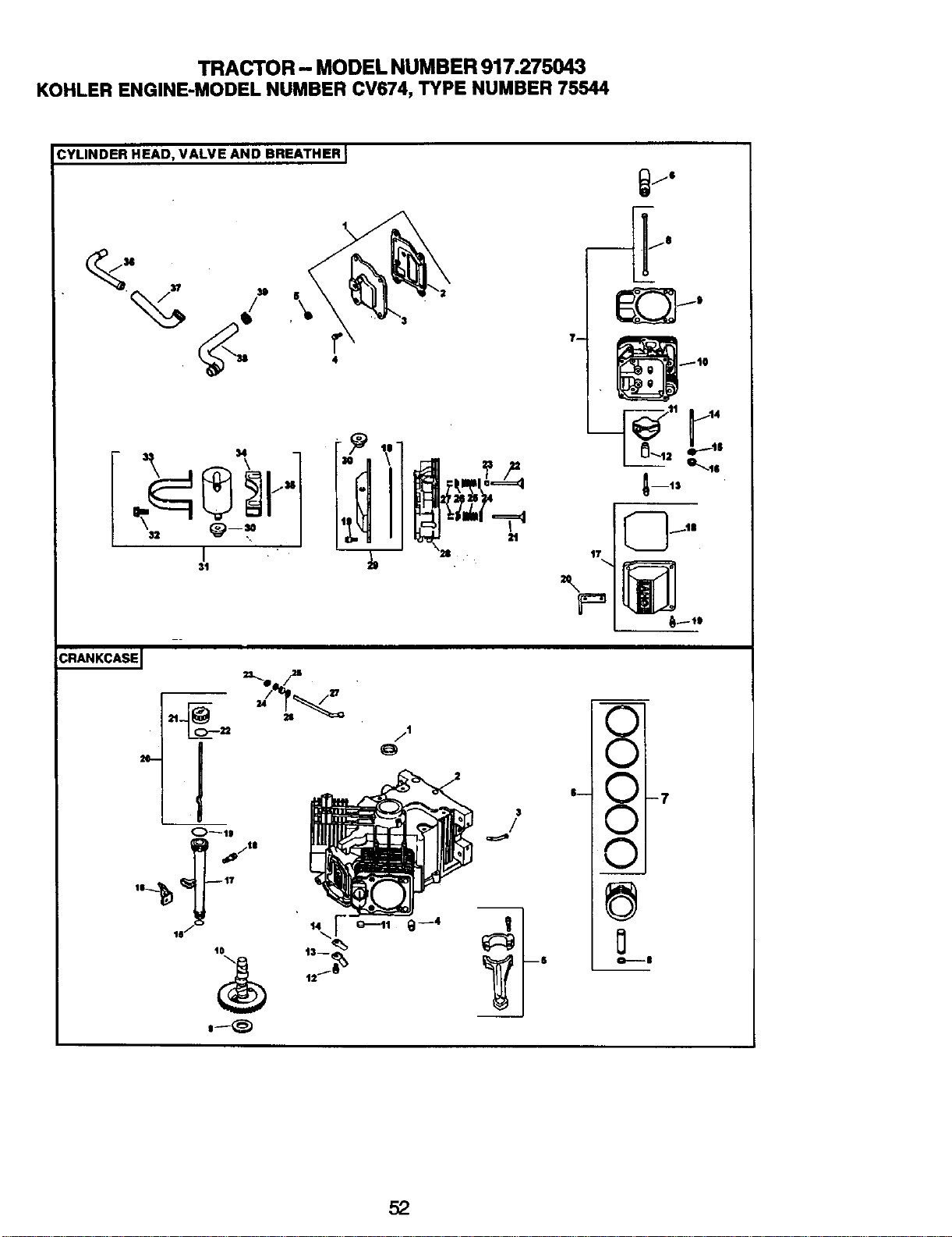
TRACTOR- MODEL NUMBER 917.275043
KOHLER ENGINE-MODEL NUMBER CV674,TYPE NUMBER 75544
:YLINDER HEAD, VALVE AND BREATHER I
37
31)
4
31 -
CRANKCASEJ
11)
$
/1
o
$
/
_m13
17
'- _1-7
v I
o----B
52
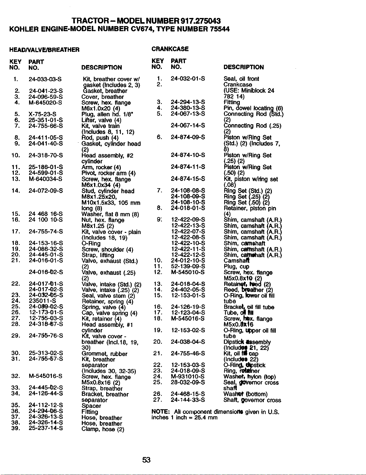
TRACTOR - MODEL NUMBER 917.275043
KOHLER ENGINE-MODELNUMBER CV674,TYPE NUMBER 75544
HEAD/VALVE/BREATHER
KEY PART
NO. NO.
1. 24-033-03-S
2. 24-041-23-S
3. 24-096-59-S
4. M-645020-S
5. X-75-23-S
6o 25-351-01 -S
7. 24-755-66-S
8. 24-411-05-S
9. 24-041-40-S
10. 24-318-70-S
11. 25-186-01 -S
12. 24-599-01 -S
13. M-640034-S
14. 24-072-09-S
15. 24 468 16-S
16. 24 100 10-S
17. 24-755-74-S
18. 24-153-16-S
19. 24-086-32-S
20. 24-445-O1-S
21. 24o016-01-S
24-016-02-S
22. 24-017-01-S
24-017-02-S
23. 24-032-05-S
24. 235011 -S
25. 24-089-02-S
26. 12-173-01-S
27. 12-755-03-S
28. 24-318-67-S
29. 24-755"76"S
30. 25-313-02-S
31. 24-755-57-S
32. M-545016-S
33. 24-445-_2-S
34. 24-126-44-S
35. 24-112-12-S
36. 24-294-06-S
37. 24-326-13-S
38. 24-326-14-S
39. 25-237-14-S
DESCRIPTION
CRANKCASE
KEY PART
NO. NO.
Kit, breather cover w/ 1.
_asket (includes 2, 3) 2.
asker, breather
Cover, breather
Screw, hex. flange 3. 24-294-13-S
4. 24-380-13-S
M6xl.0x20 (4)
Plug, allen hd. 1/8" 5. 24-067-13-S
Lifter, valve (_4)
Kit, valve tram 24-067-14-S
_dClUdes 8, 11, 12)
, push !4) 6. 24-874-09-S
Gasket, cyhnder head
2)
ead assembly, #2 24-874-10-S
cylinder
Awn,rocker (4) 24-874-11-S
Pivot, rockerarm (4)
Screw, hex. flange 24-874-15-S
M6x1.0x34 (4)
Stud, cylinder head 7. 24-108-08-S
M8x1.25x20, 24-108-09-S
M10x1.5x33, 105 mm 24-108-10-S
8. 24-018-01-S
long (8)
Washer, flat 8 mm (8)
Nut, bex. flange 9. 12-422-09-S
12-422-13-S
M8x1.25 (2)
Kit, valve cover - plain 12-422-07-S
(Includes 18, 19) 12-422-O8-S
O-Ring 12-422-10-S
Screw, shoulder (4) 12-422-11-S
Strap, lifting 12-422-12-S
Valve, exhaust (Std.) 10. 24-012.10-S
(2) 11. 52-139-09-S
Valve, exhaust (.25) 12. M-545010-S
(2)
Valve, intake (Std.) (2) 13. 24-018-04-S
Vah/e, intake (.25) (2) 14. 24-402-05-S
15. 12-153-01-S
Seal, valve stem (2)
Retainer, spring (4)
Spdng, valve (4) 16. 24-126-19-S
Cap, valve spring (4) 17. 12-123-O4-S
Kit, retainer (4) 18. M-545016-S
Head assembly, #1 19. 12-153-02-S
_dlinder
, valve cover -
breather (Inc1.18, 19, 20. 24-038-04-S
30)
Grommet, rubber 21. 24-755-46-S
Kit, breather
separator 22. 12-153-03-S
(Includes 30, 32-35) 23. 24-018-09-S
Screw, hox. flange 24. M-931010-S
M5x0.8x16 (2) 25. 28-032-09-S
Strap, breather
Bracket, breather 26. 24-468-15-S
separator 27. 24.:44-33-S
Spacer
Fitting
Hose, breather
Hose, breather
Clamp, hose (2)
DESCRIPTION
24-032-01-S Seal, oil front
Crankcase
(USE: Miniblock 24
782 14)
Fitting
Pin, dowel locating (6)
Connecting Rod (Std.)
"o)nne ngRod<.aS)
w/R,ngSel
(Std.) (2) (Includes 7,
8_ston w/Ring Set
_25) (2)
ston w/Ring Set
(.50) (2)
Kit, piston wiring set
_i_ Set (Std.) (21
Ring Set (.25) (2)
RingSet(.so)(2)
Retainer, piston pin
_"h)im,camshaft (A.R.)
Shim, camshaft (A.R,)
Shim, camshaft (A.R.)
Shim, camshaft (A.R.)
Shim, camshaft
sh,m,c=...aftI":":l
Shim, cantehaft
Camshalt
Plug, cup
Screw, hex. flange
MSx0.8xl0 (2)
RetainS0 tiled (2)
Reed, bl_ather (2)
O-Ring, lower oil fill
tube
Bracke|,.oil fill tube
Tube, oll fill
Screw, hex. flange
M5X0.81Lt6
O-Ring, ul:)peroil fill
tube
Dipstick tssembly
(|nclud_l_ 21, 22)
Kit,oil fillcap
(Inctudoe 22)
O-Ring, _pstick
Ring, r_lther
Washeft hylon (top)
Sea!z governor cross
shaft
Waslt_' (bottom)
Shaft, governor cross
NOTE: All corrtponent dimensioll= given in U.S.
inches 1 inch = 25.4 mm
53
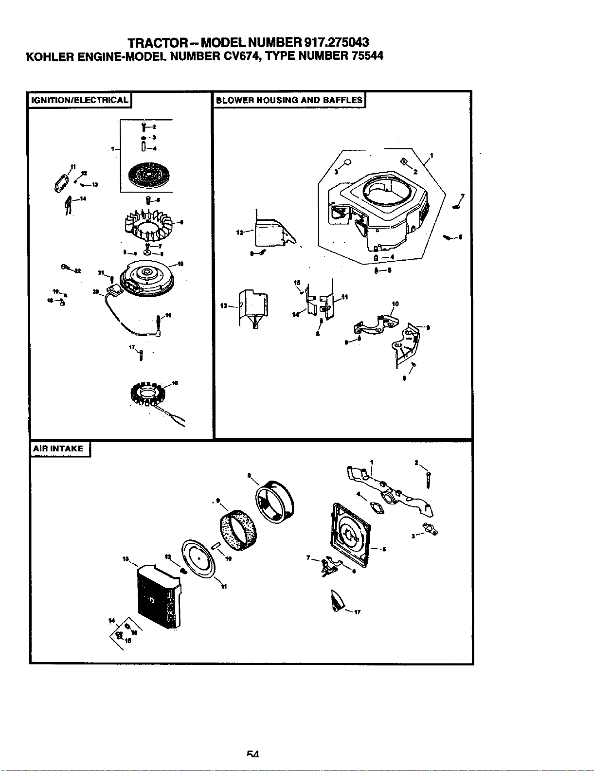
TRACTOR- MODEL NUMBER 917.275043
KOHLER ENGINE-MODEL NUMBER CV674, TYPE NUMBER 75544
IGNITIONIELECTRICAL I
#_ljz
4 _4
1T
AIR INTAKE I
14
BLOWER HOUSING AND BAFFLES I
1o
11
IF-"|
14
--10
|
$
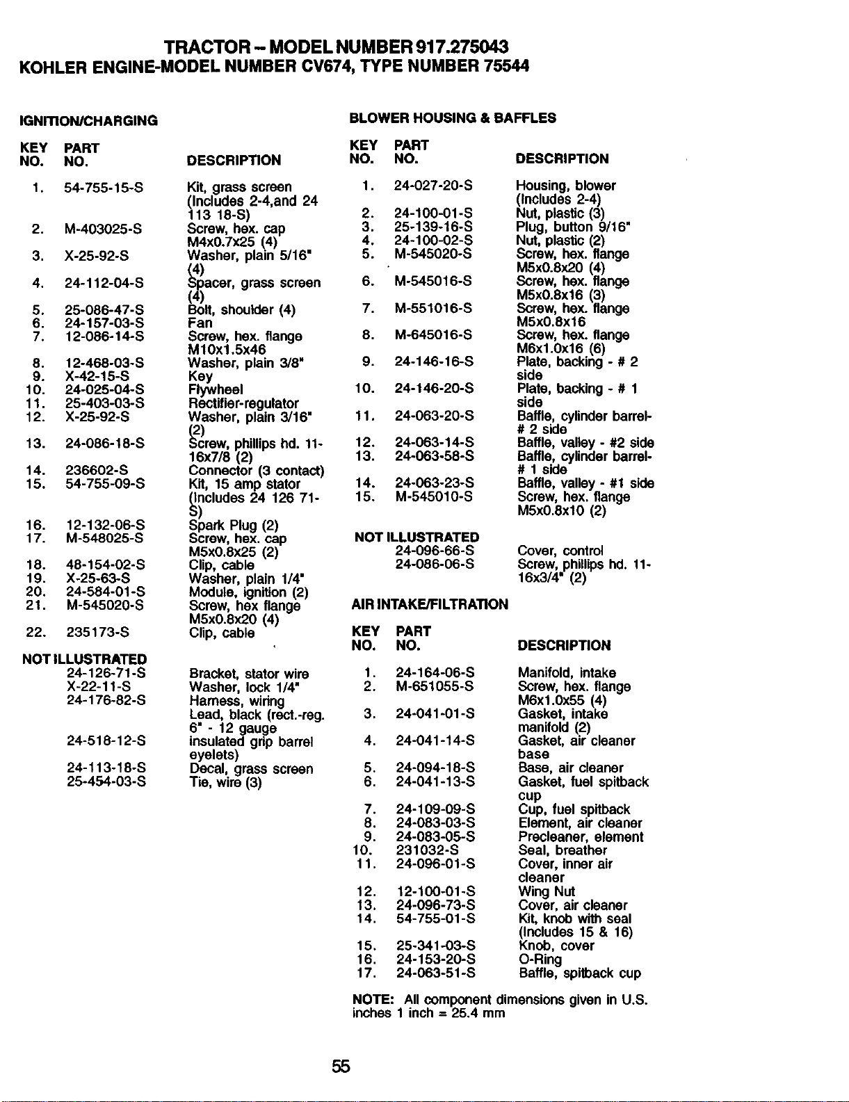
TRACTOR - MODEL NUMBER 917.275043
KOHLER ENGINE-MODEL NUMBER CV674, TYPE NUMBER 75544
IGNITION/CHARGING
KEY PART
NO. NO.
1. 54-755-15-S
2. M-403025-S
3. X-25-92-S
4. 24-112-04-S
5. 25-086-47-S
6. 24-157-03-S
7. 12-086 -14°S
8. 12-468-03-S
9. X-42-15-S
10. 24-025-04-S
11. 25-403-03-S
12. X-25-92-S
13. 24-086-18-S
14. 236602-S
15. 54-755-09-S
16. 12-132-06-S
17. M-548025-S
18. 46-154-02-S
19. X-25-63-S
20. 24-584-01-S
21. M-545020-S
22. 235173-S
NOT ILLUSTRATED
24-126-71-S
X-22-11-S
24-176-82-S
24-518-12-S
24-113-18-S
25-454-03-S
DESCRIPTION
Kit, grass screen
(includes 2-4,and 24
113 18-S)
Screw, hex. cap
M4x0.7x25 (4)
Washer, plain 5/16"
acer, grass screen
Bolt, shoulder (4)
Fan
Screw, hex. flange
M10xl.5x46
Washer, plain 3/8"
Key
Flywheel
Rectifier-regulator
Washer, plain 3/16"
_rew, phillipshd. 11-
16x7/6 (2)
Connector (3 contact)
Kit, 15 amp stator
_ncludes 24 126 71-
) 2
Spark Plug ( )
Screw, hex. cap
M5x0,8x25 (2)
Cl_p,cable
Washer, plain 1/4"
Module, ignition (2)
Screw, hex flange
M5x0.ex20 (4)
Clip, cable
Bracket, stator wire
Washer, lock 1/4"
Hamess, wiring
Lead, black (rect.-reg.
6" - 12 gauge
insulated grip barrel
eyelets)
Decal, grass screen
Tie, wire (3)
BLOWER HOUSING & BAFFLES
KEY PART
NO. NO.
DESCRIPTION
1. 24-027-20-S
2. 24-100-01-S
3. 25-139-16-S
4. 24-100-02-S
5. M-545020-S
6. M-545016-S
7. M-551016-S
8. M-645016-S
9. 24-146-16-S
10. 24-146-20-S
11, 24-063-20-S
12. 24-063-14-S
13. 24-063-58-S
14. 24-063-23-S
15. M-545010-S
NOT ILLUSTRATED
24-096-66-S
24-086-06-S
Housing, blower
(Includes 2-4)
Nut, plastic (3) ,
Plug, button 9/16
Nut, plastic (2)
Screw, hex. flange
M5x0.8x20 (4)
Screw, hex. flange
M5x0.Sxf6 (3)
Screw, hex. flange
M5x0.8x16
Screw, hex. flange
M6xl.0x16 (6)
Plate, backing - # 2
side
Plate, backing - # 1
side
Baffle, cylinder barrel-
# 2 side
Baffle, valley - #2 side
Baffle, cylinder barrel-
# 1 side
Baffle, valley - #1 side
Screw, hex. flange
M5x0.exl0 (2)
Cover, control
Screw, phillipshd. 11-
16x3/4" (2)
AIR INTAKE/FILTRATION
KEY PART
NO. NO, DESCRIPTION
1. 24-164°06-S Manifold, intake
2. M-651055-S Screw, hex. flange
M6xl.0x55 (4)
3. 24-041°01 "S Gasket, intake
manifold (2)
4. 24-041-14-S Gasket, air cleaner
base
5. 24-094-18-S Base, air cleaner
6. 24-041-13-S Gasket, fuel spitback
cup
7. 24-109-09-S Cup, fuel spitback
8. 24-083-03-S Element, air cleaner
9. 24-083-05-S Precleener, element
10. 231032-S Seal, breather
11. 24°096-01-S Cover, inner air
cleaner
12. 12-100-01-S Wing Hut
13. 24-096-73-S Cover, air cleaner
14. 54-755-01-S Kit, knob with seal
(Includes 15 & 16)
15. 25-341-03-S Knob, cover
16. 24-153-20-S O-Ring
17. 24-063-51-S Baffle, spitback cup
NOTE: All component dimensions given in U.S.
inches 1 inch = 25.4 mm
55
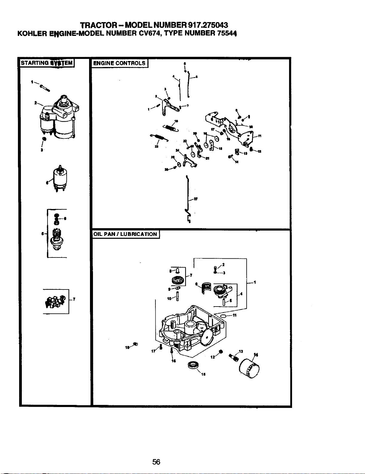
TRACTOR - MODEL NUMBER 917.275043
KOHLER ENGINE-MODEL NUMBER CV674, TYPE NUMBER 75544
S:AWrnNGi-_S-TEMJ
$
ENGINE CONTROLS I s - -
OIL PAN I LUBRICATION J
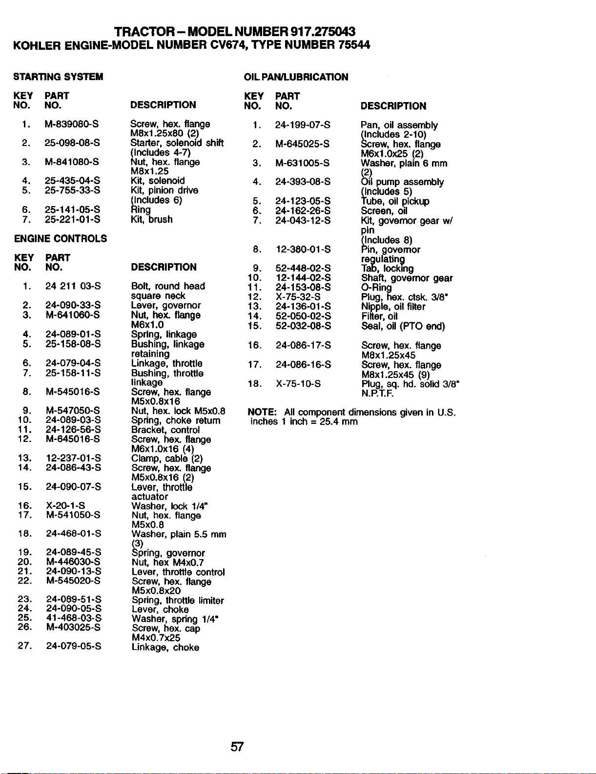
TRACTOR - MODEL NUMBER 917.275043
KOHLER ENGINE-MODEL NUMBER CV674, TYPE NUMBER 75544
STARTING SYSTEM
KEY PART
NO. NO.
1. M-839080-S
2. 25-098-08-S
3. M-841080-S
4. 25-435-04-S
5. 25-755-33-S
6. 25-141-05-S
7. 25-221-01-S
ENGINE CONTROLS
KEY PART
NO. NO.
1. 24 211 03-S
2. 24-090-33-S
3. M-641060-S
4. 24-089-01-S
5. 25-158-08-S
6. 24-079-04-S
7. 25-158-11-S
8. M-545016-S
9. M-547050-S
10. 24-089-03-S
11. 24-126-56-S
12. M-645016-S
13. 12-237-01-S
14. 24-086-43-S
15. 24-090-07-S
16. X-20-1-S
17. M-541050-S
18. 24-468-01-S
19. 24-089-45-S
20. M-446030-S
21. 24-090-13-S
22. M-545020-S
23. 24-089-51-S
24. 24-090-05-S
25. 41-468-03-S
26. M-403025-S
27. 24-079-05-S
OIL PAN/LUBRICATION
KEY PART
DESCRIPTION NO. NO.
Screw, hex. flange 1. 24-199-07-S
MSx1.25x80 (2)
Starter, solenoid shift 2. M-645025-S
(Includes 4-7)
Nut, hex. flange 3. M-631005-S
M8xl.25
Kit, solenoid 4. 24-393-08-S
Kit, pinion drive
_.ncludes 6) 5. 24-123-05-S
Hing 6. 24-162-26-S
Kit, brush 7. 24-043-12-S
DESCRIPTION
Bolt, round head
square neck
Lever, governor
Nut, hex. flange
M6x1.0
Spring, linkage
Bushing, linkage
retaining
Linkage, throttle
Bushing, throttle
linkage
Screw, hex. flange
M5xO.8xl 6
Nut, hsx. lock M5x0.8
Spring, choke retum
Bracket, control
Screw, bex. flange
M6xl.0x16 (4)
Clamp, cable (2)
Screw, hex. flange
M5xO.8x16 (2)
Lever, throttle
actuator
Washer, lock 1/4"
Nut, hex. flange
M5x0.8
Washer, plain 5.5 mm
_ring, governor
Nut, hex M4x0.7
Lever, throttle control
Screw, bex. flange
M5x0.8x20
Spring, throttle limiter
Lever, choke
Washer, spring 1/4"
Screw, bex. cap
M4xO.7x25
Linkage, choke
DESCRIPTION
8, 12-380-01-S
9. 52-448-02-S
10. 12-144-02-S
11. 24-153-08-S
12. X-75-32-S
13. 24-136-01-S
14. 52-050-02-S
15. 52-032-08-S
Pan, oil assembly
,_.cludes 2-10)
rew, hex. flange
M6xl.0x25 (2)
Washer, plain 6 mm
2)
il pump assembly
(Includes 5)
Tube, oil pickup
Screen, oil
Kit, governor gear w/
pin
_ncludes 8)
in, governor
regulating
Tab, locking
Shaft, governor gear
O-Ring
Plug, hex. ctsk. 3/8"
Nipple, oil filter
Filter, oil
Seal, oil (PTO end)
16. 24-086-17-S Screw, hex. flange
M8x1.25x45
17. 24-086-16-S Screw, hex. flange
M8x1.25x45 (9)
18. X-75-10-S Plug, sq. hd. solid 3/8"
N.P.T.F.
NOTE: All component dimensions given in U.S.
inches 1 inch = 25.4 mm
57
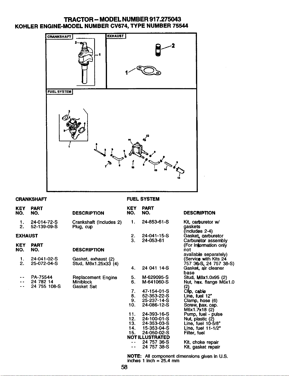
TRACTOR - MODEL NUMBER 917.275043
KOHLER ENGINE-MODEL NUMBER CV674, TYPE NUMBER 75544
CRANKSHAFT I
i
-1
EXHAUSTJ
FUEL SYSTEM [
• .
16
CRANKSHAFT
KEY PART
NO. NO.
1. 24-014-72-S
2. 52-139-09-S
EXHAUST
KEY PART
NO. NO.
1. 24-041-02-S
2. 25-072-04-S
-- PA-75544
-- 24 782 14
-- 24 755 108-S
DESCRIPTION
Crankshaft (includes 2)
Plug, cup
DESCRIPTION
Gasket, exhaust (2)
Stud, MSx1.25x33 (4)
Replacement Engine
Miniblock
Gasket Set
FUEL SYSTEM
KEY PART
NO. NO.
DESCRIPTION
1. 24-853-61-S
2. 24-041-15-S
3. 24-053-61
4. 24041 14-S
5. M-629095-S
6. M-641060-S
7. 47-154-01-S
8. 52-353-22-S
9. 25-237-14-S
10. 24-086-12-S
11. 24-393-16-S
12. 24-100-01-S
13. 24-353-03-S
14. 15-353-04-S
15. 24-050-02-S
NOTILLUSTRATED
-- 24 757 36-S
-- 24 75738-S
Kit, carburetor w/
_askets
ncludes 2-4)
Gasket, narburetor
Carburetor assembly
(For inlon'nationonly
not
available separately)
(Service with Kits 24
757 36-S, 24 757 38-S)
Gasket, air cleaner
base
Stud, MBx1.0x95 (2)
Nut, hex. flange M6xl.0
Line, fuel 12'
Clamp, hose (6)
Screw, bex. cap.
M6x1.7x18 (2)
Pump, fuel - pulse
Nut, plastic (2)
Line, fuel 10-5/8"
Line, fuel 11-1/2"
Filter, fuel
Kit, choke repair
Kit, gasket repair
NOTE: All component dimensions given in U.S.
inches 1 inch = 25.4 mm
58

SUGGESTED GUIDE FOR SIGHTING SLOPES FOR SAFE OPERATION
1. Fold this page along dotted line indicated above.
2. Hold page before you so that its left edge Is vertically parallel to a tree
trunk or other upright structure.
3. Sight across the fold in the direction of hill elope you want to measure.
4. Compare the angle of the fold with the slope of the hill.

Get it fixed, at your home or ours!
Forrepairof majorbrandappliancesInyour own home...
nomatterwhomadeit,nomatterwhosoldrd
1-800-4-MY-HOME _ Any,r_ dayorn_t
(1-8004694663) (U.S_. andCanada)
_m _Jmlllll_=l
For repairofcarry-inproductslikevacuums, lawnequipment, and
electronics,callfor the nearest Seam Paris and Re_ Center.
1-800-488-1222 /_ne, dayorniglt(U.SAorgy)
w.8omlLcont
Forthereplacementparts,accessoriesandowner'smanuals
thatyou need to do-it-yourself,callSears PartsDirectSM!
1-800-366-PART 6a.m.-11 p.m., 7daysaweek
(1-800-366-7278) (U_S.A.only)
www_mct
TopurchaseorinquireaboutaSearsServiceAgreement
orSearsMaintananceAgreemant:
1-800-827-6655 (U.SA) 1-800-361-6665 (Canada)
7 am.- 5 pJ_.,CST, MOR- Sat. 9 a_n.- 8 pJ_. EST, M - F, 4 p.m.Sat.
Parapecirsen4ciode repara:k_ a
domlcio, y pera ordenarpieza=
1.888.SU.flOGAR sM
0-e_-7e4-6427)
Au_ pourse_ce enfmr_Cs:
1.eOO.LE.FOYERMc
(1_00_3-_37)
www.sesm.ca
©Sea_ Boeb_andCo.
® Registered Trademark / Trademark / Service Mark of Seam, Roebuck and Co.
® Marca Registrada / TMMarca de Fdbrica / sMMama de Servicio de Seam, Roebuck and Co,
MC MD
Marque de commerce / Marque d_pos_a de Sears, Roebuck and Co.
182938 2.11.02 RD Printed in U.S.A.


