Loading ...
MODEL LA553WH
Page 2
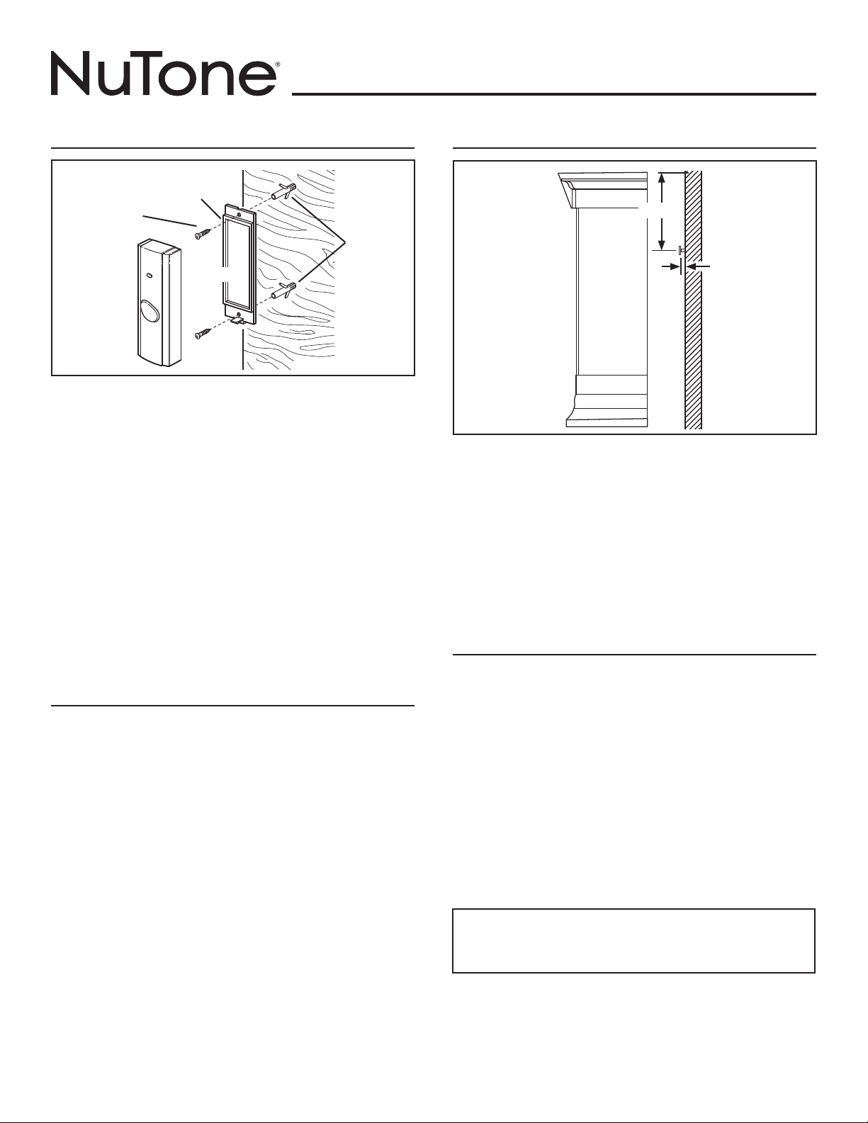
Figure 6
MOUNT PUSHBUTTON
Refer to Figures 1 and 6.
1. After selecting usable locations in previous section, go to pushbutton
location.
2. Insert small, flat-blade screwdriver into bottom of pushbutton and twist
to separate its mounting base.
3. Make sure pushbutton mounting location is level.
4. Position pushbutton mounting base with “TOP” arrow correctly
oriented and mark base mounting holes locations.
5. Drill two (2) holes, 1/16” diameter if using supplied screws alone or
3/16” diameter if using supplied plastic anchors and screws, at base
mounting hole locations.
6. If 3/16” diameter holes were drilled, insert supplied plastic anchors.
7. Secure pushbutton base to mounting location with two (2) supplied
screws.
8. Make sure black O-ring is completely seated in its mounting base
groove with round edge at top and flat edge at bottom.
9. Hook pushbutton top catch onto top of base, swing pushbutton into
position and press bottom of pushbutton until it securely snaps onto
base.
SET VOLUME PROCEDURE
Refer to Figure 5.
There are four (4) volume levels which are accessed sequentially.
1. Press and release pushbutton to sound chime tone.
2. Press and release “Volume” button to hear the next volume setting.
3. If chime tone is not sounding when “Volume” button is pressed then
chime will sound a beep to indicate volume setting.
4. Volume setting cycles from loud to medium-loud, medium-soft and soft
then back to loud.
5. Repeat Step 2 until desired volume level is set.
6. Last volume setting is remembered.
7. Press and release pushbutton to sound chime tone and confirm
desired volume setting.
BASE
PLASTIC
ANCHORS
TOP
BLACK
“O” RING
MOUNTING
SCREWS
This device complies with Part 15 of the FCC rules.
Operation is subject to the following two conditions:
1. This device may not cause harmful interference, and
2. This device must accept any interference received, including
interference that may cause undesired operation.
Regulatory Information
The user is cautioned that changes or modifications not expressly
approved by the party responsible for regulatory compliance
could void the user’s authority to operate this equipment.
MOUNT CHIME
Refer to Figure 7.
1. Go to selected chime location.
2. Measure 1-15/16” down and centered from top of chime location and
mark mounting screw position.
3. Drill a hole, 1/16” diameter if using supplied screw alone or 3/16”
diameter if using supplied plastic anchor and screw, at marked
mounting screw location.
4. If 3/16” diameter hole was drilled, insert supplied plastic anchor.
5. Insert and tighten top mounting screw until 1/8” remains protruding.
6. Place chime keyhole slot over mounting screw and apply slight
downward force to seat keyhole slot on mounting screw.
7. Level chime.
TROUBLESHOOTING GUIDE
1. Chime does not sound:
a. If pushbutton LED doesn’t light when pushbutton is pressed then:
1. Check battery polarity in pushbutton.
2. Replace battery in pushbutton.
b. Replace batteries in chime.
c. Bring pushbutton in area of chime and test:
1. If chime sounds then change location of chime.
2. If chime does not sound then conduct erase procedure per note
at end of “Learn” Procedure then conduct “Learn” Procedure,
Steps 1 through 9.
2. Chime loses volume or changes tone:
a. Change batteries in chime.
3. Chime sounds when pushbutton is not pressed:
a. Release pushbutton catch at bottom and check inside for signs of
moisture; check O-ring for cracks or damage.
b. Conduct erase procedure per note at end of “Learn” Procedure then
conduct “Learn” Procedure, Steps 1 through 9.
Figure 7
1/8”
1-15/16”
Loading ...
Loading ...
Loading ...