Evolve
™
monitor arm series
UNIVERSAL INSTALLATION INSTRUCTIONS

IMPORTANT SAFETY INSTRUCTIONS AND WARNINGS
Read before using!
Read and follow all instructions and warnings before use. Save these instructions for future reference.
• Use this product only in the manner intended by the manufacturer. If you have questions, contact the
manufacturer.
• This product contains small items that could be a choking hazard if swallowed. Keep away from
children.
• Make sure the desk or mounting surface can support the combined weight of the mount and the
screens.
• Do not extend monitors behind the base.
• Never exceed the maximum load capacity.
• Minimum load capacity must be reached for each motion arm.
• Load capacity may vary depending on the type of installed monitor or accessory.
• There can be no more than two monitor arms in a monitor arm assembly.
• The motion arm is always the nal arm in a monitor arm assembly; there can be no xed arms after a
motion arm is used.
• Current Evolve congurations are limited to a maximum of six monitors.
• Hand tighten screws only. Do not use power tools.
• When connecting and routing monitor cables and power cords, make sure the cables and cords are
long enough to accommodate the full range of motion of the monitor arms.
• Check joint parts every two months to make sure the screws have not loosened.
• This product is only compatible with Fellowes Evolve monitor arm accessories.
• This product is intended for indoor use only.
Page 2
Please review these instructions before beginning the installation. Check that all the components needed for installation
were provided with your order. Refer to the illustrations for component identication and the table for component quantity
for the model you are installing. Contact your supplier if any parts are missing. Do not discard the packaging until the
product works to your satisfaction.
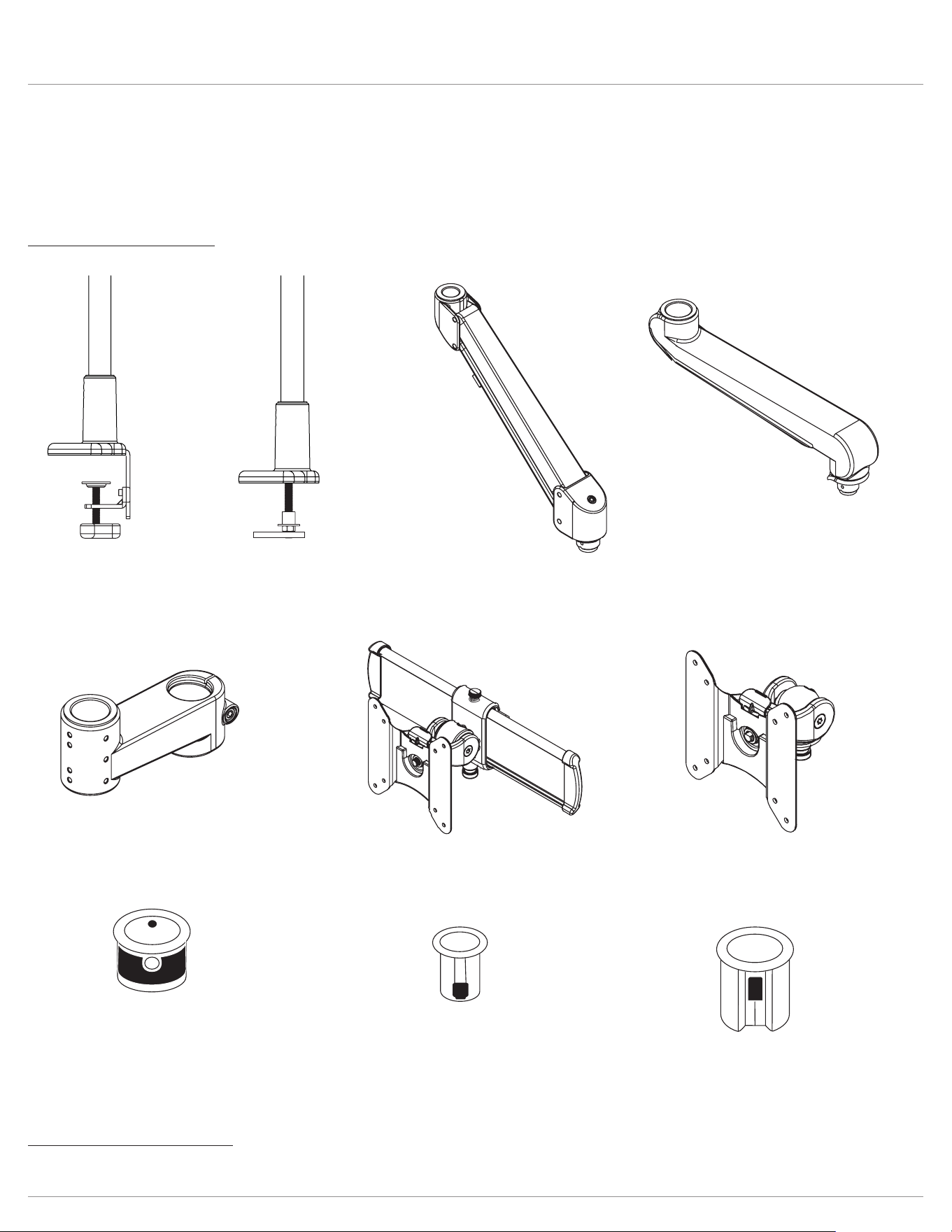
Components and tools
Additional tools required
• Phillips screwdriver
Evolve Components and tools
desk clamp
grommet mount
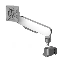
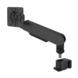
motion arm
xed arm
arm stem
vesa mount
slider mount
standard bushing
preinstalled on stem arm
& xed arm
small bushing
For VESA & slidermounts
reducer bushing
For VESA & slidermounts
Page 3
IMPORTANT: When a monitor arm assembly consists of two individual monitor arms, a xed arm is always the rst
component attached to the single or dual stem.
Here are a few more model number examples:
Model numbers
The model number for each of the Evolve models communicates essential information about the product: how many
monitor arm assemblies, the specic type(s) of monitor arms in an assembly, and whether a VESA mount or slider mount is
used. Having an understanding of the model numbers helps you to visualize the installation.
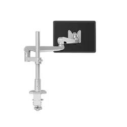
Evolve Introduction
Evolve2–FMS
Evolve2–FMS
Evolve2–FMS
Evolve2–FMS
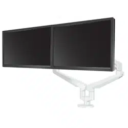
Evolve2-FMS indicates two monitor arm assemblies,
each consisting of a motion arm connected to a fixed arm,
with a slider mount connected to the motion arms.
example:
number of monitor arm assemblies: 1, 2, or 3
type of monitor arm(s): F=fixed and/or M=motion
S indicates slider mount; its absence indicates VESA mount
Evolve1–M
Evolve2–FS
Evolve3–FF
Evolve1-M indicates one monitor arm assembly consisting of a motion arm with a VESA mount connected to it.
Evolve2-FS indicates two monitor arm assemblies, each consisting of a fixed arm with a slider mount connected to it.
Evolve3-FF indicates three monitor arm assemblies, consisting of two fixed-fixed arms with VESA mount, plus one VESA mount
connected to a single stem. When three monitors are used, the third arm is always a VESA mount connected to a single stem.
This is true even with Evolve3-FMS when the other two assemblies are topped with a slider mount.
Conguration pages
The congurations shown on the following
pages show the basic assembly of the major
components for each of the Evolve models.
The illustrations are designed to
assist you when following the detailed
assembly steps that begin on page 10.
Before beginning the assembly, always
refer to the conguration page for the model
number you are installing.
Assembly steps
The assembly steps beginning on page 10 show the details of component assembly and also cover intermediate steps.
These include procedures for applying a rubber pad to the pole base, attaching VESA plates to monitors, organizing cables
and power cords, and making adjustments.
The assembly steps are general instructions that can be applied to each of the specic models. For example, most of
the illustrations show VESA mounts. The same procedures apply to slider mounts, as well. Similarly, when a xed-motion
monitor arm assembly is shown, the same principles apply to xed-xed arm assemblies or to single arm assemblies. The
key is to refer to the conguration page for the specic model being installed.
models page number
Evolve1-F
Evolve2-F
Evolve2-FS
5
Evolve1-M
Evolve1-MS
Evolve2-M
Evolve2-MS
Evolve4-MS
6
Evolve1-FF
Evolve2-FF
Evolve3-FF
Evolve4-FF
Evo l v e 6 - FF
7
Evolve1-FM
Evolve2-FM
Evolve2-FMS
Evolve3-FMS
Evolve4-FM
Evolve4-FMS
Evolve6-FMS
8
Evolve-Stubby 9
Evolve1-F
Evolve2-F
Evolve2-FS
stem
stem
BUILD 1ST
Completes Evolve1-F assembly
BUILD 2ND
Completes Evolve2-F assembly
or
Completes Evolve2-FS
assembly
reducer
bushing
reducer
bushing
slider or VESA
slider or VESA
1
2
3
5
4
4
Configuration page example:
Page 4
Evolve Congurations
Component assembly
1. Secure pole mount to worksurface.
2. Slide stem arm over pole and secure in place with the
5mmAllenkey.
3. Insert xed arm to armstem.
4. Attach reducer bushing to VESA or slider. Insert VESA
or slider to xed arm.
5. For dual display congurations, reverse the second
stem arm on the pole, then repeat conguration on
second stem arm.
6. Attach VESA plate to back of monitor.
7. Attach displays using the quick release feature.
8. Adjust tension on VESA or slider.
Evolve1-F
Evolve2-F
Evolve2-FS
Evolve1-F
Evolve2-F
Evolve2-FS
stem
stem
BUILD 1ST
Completes Evolve1-F assembly
BUILD 2ND
Completes Evolve2-F assembly
or
Completes Evolve2-FS
assembly
reducer
bushing
reducer
bushing
slider or VESA
slider or VESA
1
2
3
5
4
4
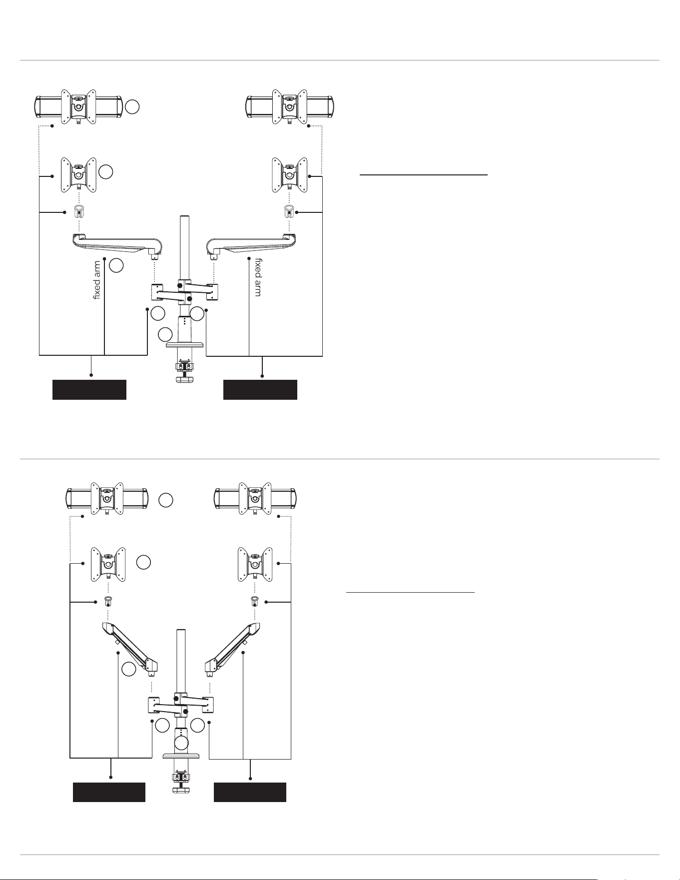
Evolve1-M
Evolve1-MS
Evolve2-M
Evolve2-MS
Evolve4-MS
motion arm
stem
stem
motion arm
BUILD 1ST
Completes Evolve1-M assembly
or
Completes Evolve1-MS assembly
BUILD 2ND
Completes Evolve2-M assembly
or
Completes Evolve2-MS assembly
Small
bushing
Small
bushing
slider or VESA
slider or VESA
4
4
3
1
52
Evolve1-M
Evolve1-MS
Evolve2-M
Evolve2-MS
Evolve4-MS
Component assembly
1. Secure pole mount to worksurface.
2. Slide stem arm over pole and secure in place with the
5mmAllenkey.
3. Insert motion arm to armstem.
4. Attach reducer bushing to VESA or slider. Insert VESA or
slider to xed arm.
5. For dual display congurations, reverse the second stem
arm on the pole, then repeat conguration on second stem
arm.
6. Attach VESA plate to back of monitor.
7. Attach displays using the quick release feature.
8. Adjust tension on VESA or slider.
Page 5
Evolve Congurations
Evolve1-FF
Evolve2-FF
Evolve3-FF
Evolve4-FF
Evolve6-FF
Component assembly
1. Secure pole mount to worksurface.
2. Slide stem arm over pole and secure in place with the
5mmAllenkey.
3. Insert xed arm to stem arm.
4. Insert xed arm to xedarm.
5. Attach reducer bushing to VESA or slider. Insert VESA
or slider to xed arm.
6. For dual display congurations, reverse the second
stem arm on the pole, then repeat conguration on
second stem arm.
7. For triple display congurations, reverse the second
stem arm on the pole, then add a third stem arm. Attach
reducer bushing to VESA and insert VESA to third
stem arm.
8. Attach VESA plate to back of monitor.
9. Attach displays using the quick release feature.
10. Adjust tension on VESA or slider.
Evolve1-FF
Evolve2-FF
Evolve3-FF
Evolve4-FF
Evolve6-FF
stem
VESA
stem
stem
BUILD 1ST BUILD 2ND
BUILD 3RD
reducer
bushing
reducer
bushing
reducer
bushing
Completes Evolve1-FF assembly Completes Evolve2-FF assembly
slider or VESA
slider or VESA
Completes Evolve3-FF assembly
1
2 6
7
4
5
5
3
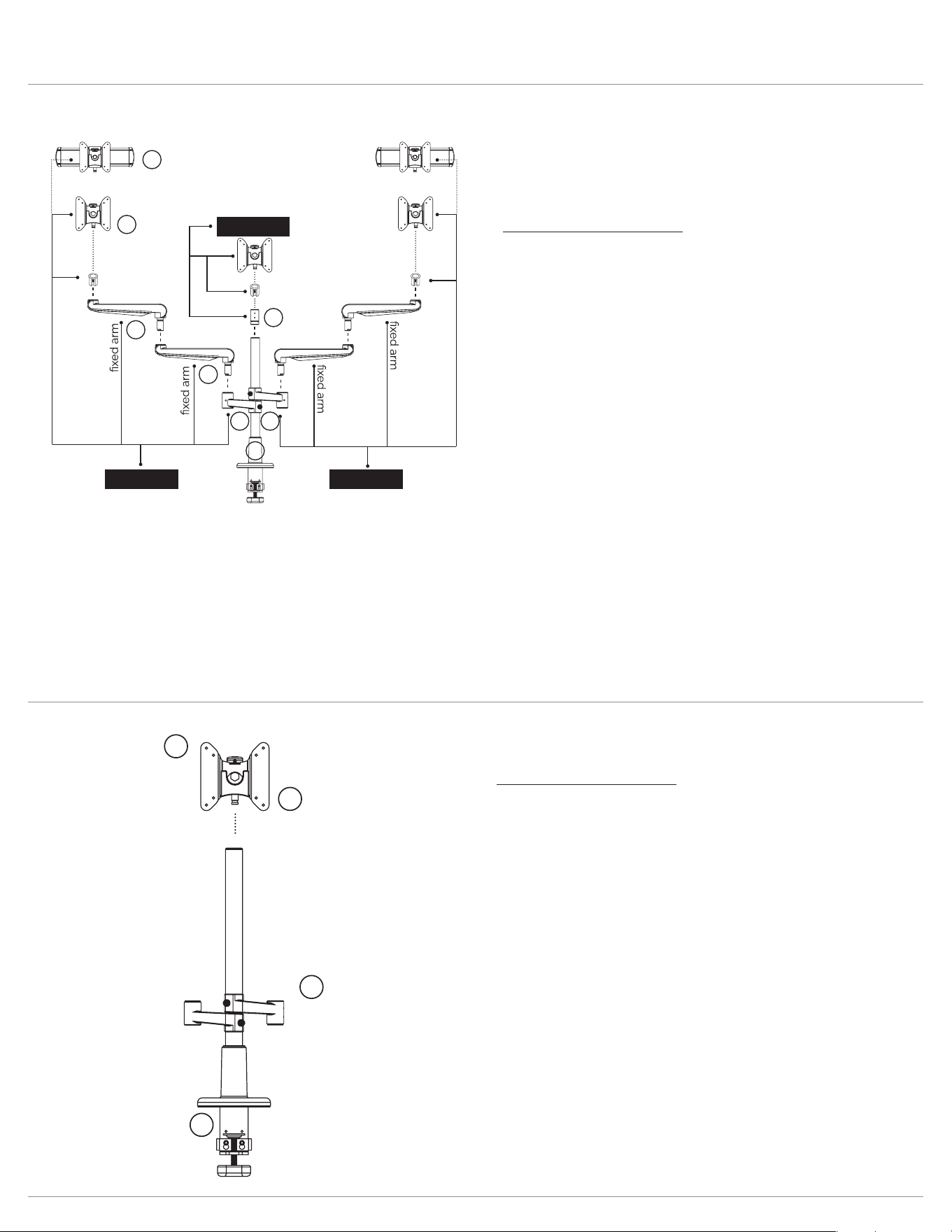
Evolve-Stubby
stem
VESA
4
3
1
2
Component assembly
1. Secure pole mount to worksurface.
2. Slide stem arm over pole and secure in place with the
5mmAllenkey.
3. Attach VESA plate to back of monitor.
4. Adjust tension on VESA.
Evolve-Stubby
Page 6
Evolve Congurations and pole mount
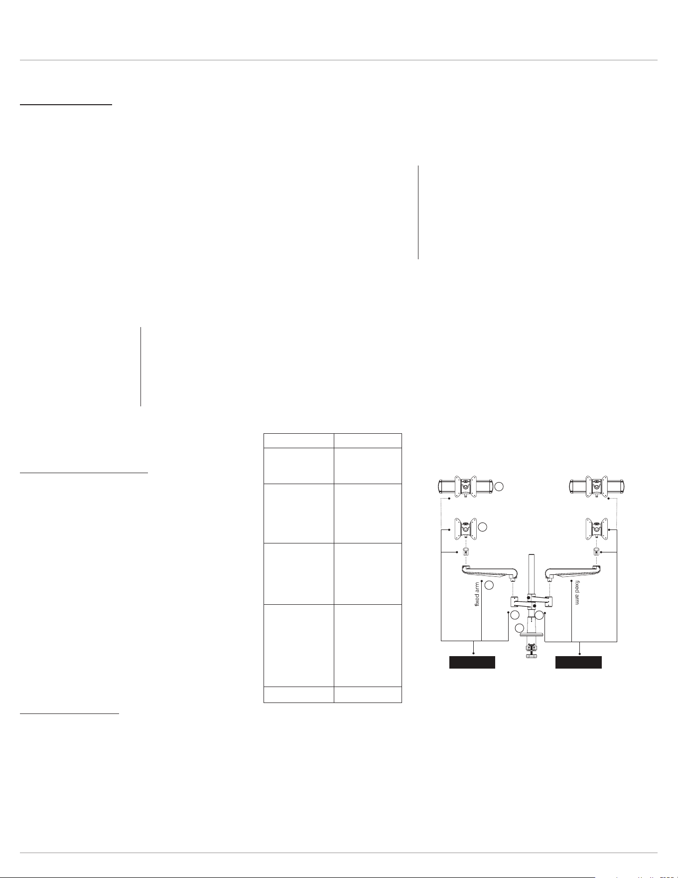
Evolve1-FM
Evolve2-FM
Evolve2-FMS
Evolve3-FMS
Evolve4-FM
Evolve4-FMS
Evolve6-FMS
motion arm
stem
motion arm
stem
BUILD 1ST BUILD 2ND
VESA
BUILD 3RD
reducer
bushing
small
bushing
small
bushing
slider or VESA
slider or VESA
Completes Evolve1-FM assembly Completes Evolve2-FM assembly
or
Completes Evolve2-FMS assembly
Completes Evolve3-FMS assembly
5
5
4
7
3
2
6
1
Evolve1-FM
Evolve2-FM
Evolve2-FMS
Evolve3-FMS
Evolve4-FM
Evolve4-FMS
E v o l v e 6 - F M S
Component assembly
1. Secure pole mount to worksurface.
2. Slide stem arm over pole and secure in place with the
5mmAllenkey.
3. Insert xed arm to stem arm.
4. Insert motion arm to xedarm.
5. Attach small bushing to VESA or slider. Insert VESA or
slider to motion arm.
6. For dual display congurations, reverse the second
stem arm on the pole. Then, repeat conguration on
second stem arm.
7. For triple display congurations, reverse the second
stem arm on the pole, then add a third stem arm. Attach
reducer bushing to VESA and insert VESA to third
stem arm.
8. Attach VESA plate to back of monitor.
9. Attach displays using the quick release feature.
10. Adjust tension on motionarm. Adjust tension on VESA
and/or slider.
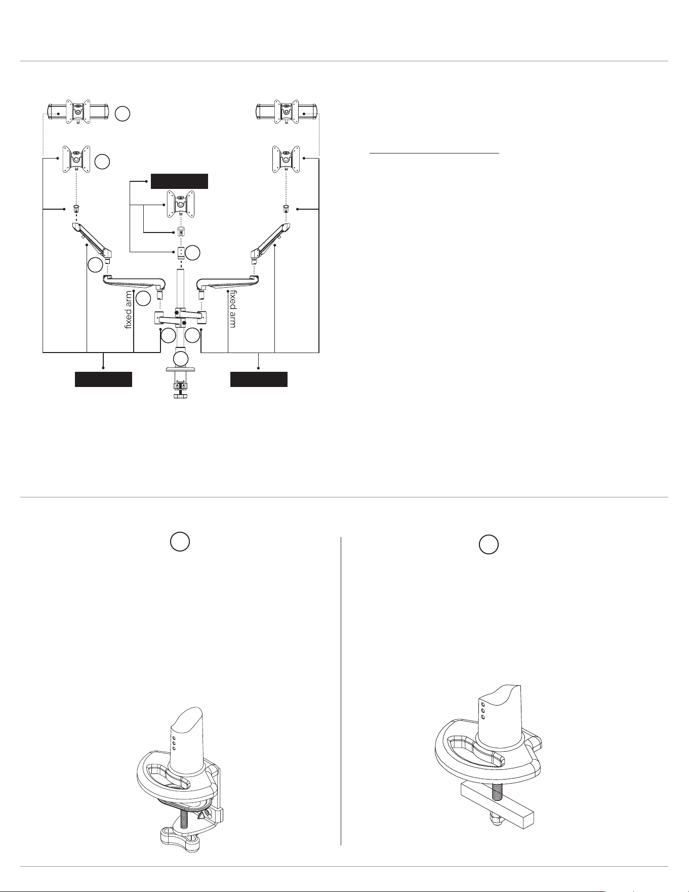
You will receive parts to accommodate either the desk clamp mount or the grommet mount.
Option 2
Grommet mount
Convert the desk clamp
mount to a grommetmount
For worksurfaces up to
1.5” thick.
Option 1
Desk clamp
Secure pre-assembled desk clamp
mount
to worksurface.
For worksurfaces between
0.6" - 2.99" thick.
1
2
Page 7
Evolve Assembly (desk clamp)
Step 2B
Replace the clamping
component in the lower
position and secure with
the 4mmAllenkey.
Step 2A
Remove the clamping
component from the
upper position with the
4mmAllenkey.
Optional adjustment
for thicker worksurfaces
1.38”-2.99”
Step 1
Adhere the adhesive pad
underneath the base to
protect the worksurface.
Step 2 (optional)
Adjust clamp positioning
to accommodate a thicker
worksurface.
Step 3
Slide onto worksurface
to desired position.
Step 4
Twist to tighten the desk
clamp on the worksurface.
1
1
2
3
3
2
4
4
For worksurface 0.66”- 2.2” For worksurface up to 1.5”
Page 8
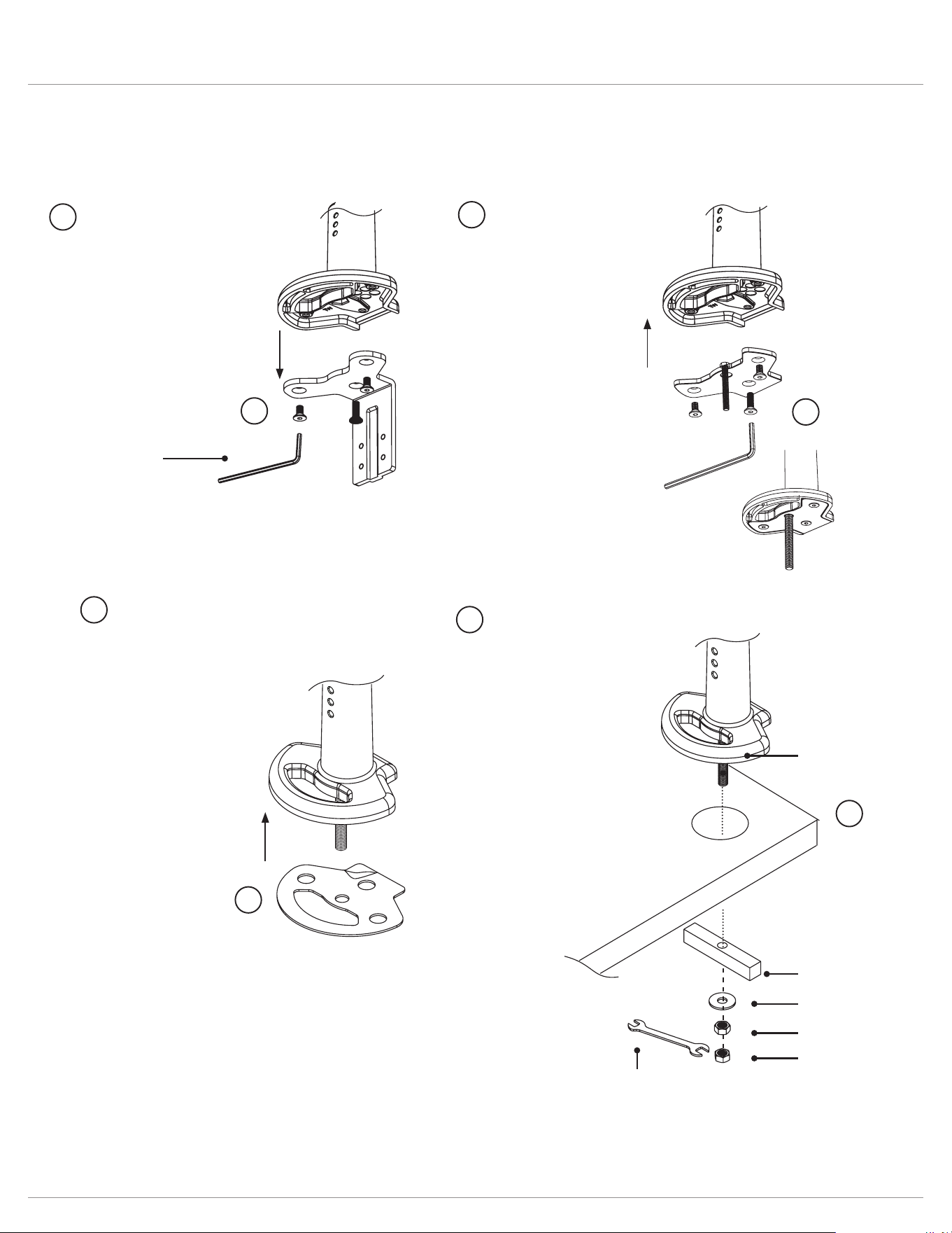
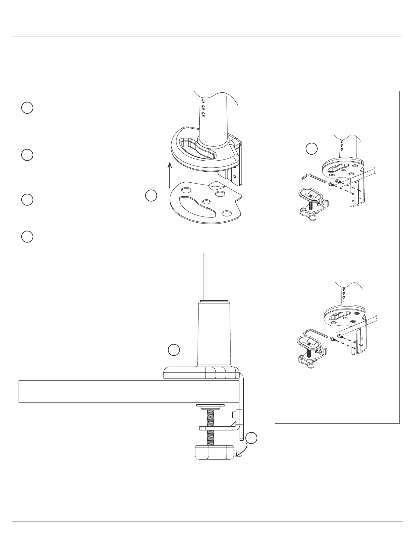
Evolve Assembly (grommet mount)
4mm Allen key
(Included)
Step 1
Remove the 3 screws with
the 4mmAllenkey.
Step 3
Adhere the adhesive pad
underneath the base to
protect the worksurface.
Step 2
Insert the large screw to
the grommet plate and
reattach the 3 screws with
the 4mmAllenkey.
Step 4
Complete the grommet
mount assembly with the
remaining components.
(bolt should be visible
under worksurface)
14 mm nut
14 mm nut
washer
plate
14 mm
wrench
(Included)
bolt
For worksurface up to 1.5”
1
2
2
3
4
3
4
1
Page 9
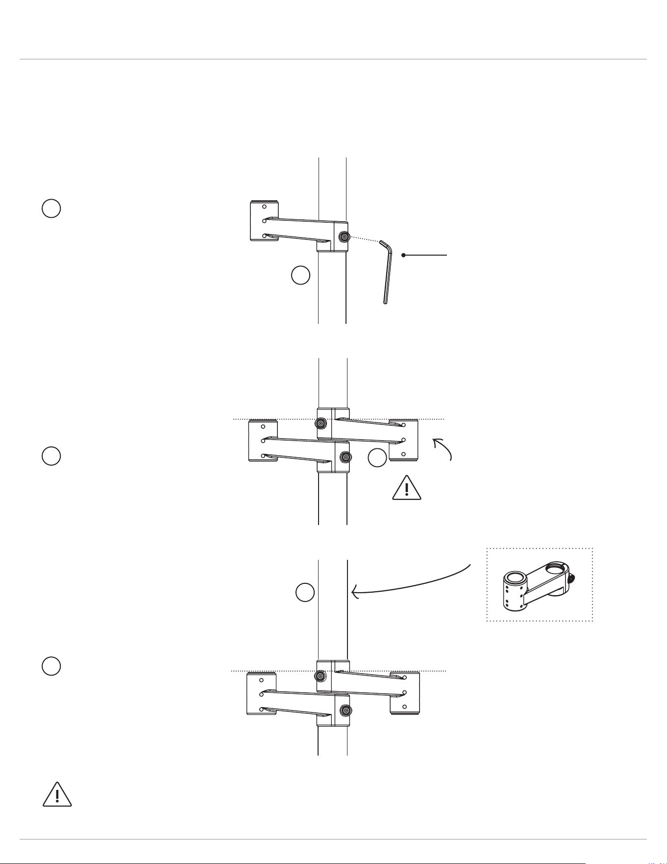
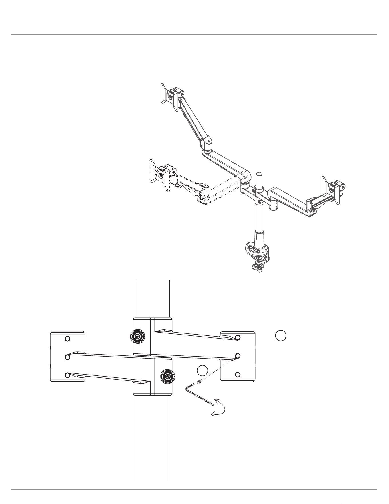
Evolve Stem arm
NOTE
Stem arm is reversed
for even alignment
Step 1
Slide stem arm over
pole and secure with the
5mmAllenkey.
Step 2
Reverse the second stem
arm over pole as shown
and secure with the
5mmAllenkey.
Step 3
Slide VESA stem arm
over pole and secure
with the 5mmAllenkey.
Stem arm is stacked on top
to hold center monitor.
Each diagram/step may not applicable to your product conguration.
Single display conguration
Dual display conguration
Triple display conguration
5mm Allen key
(Included)
NOTE: armstems must be secured to pole before attaching additional components
1
1
2
3
3
2
Page 10
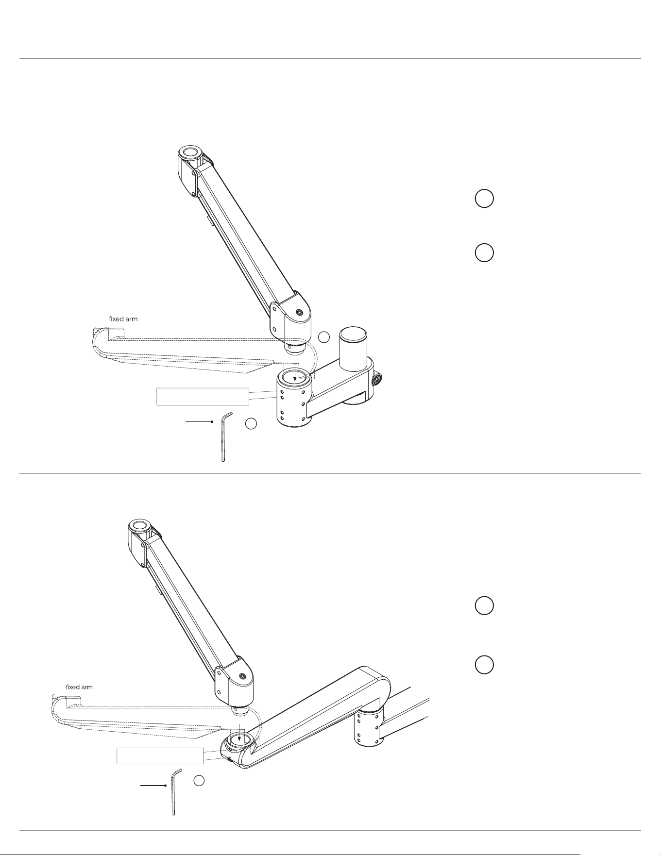
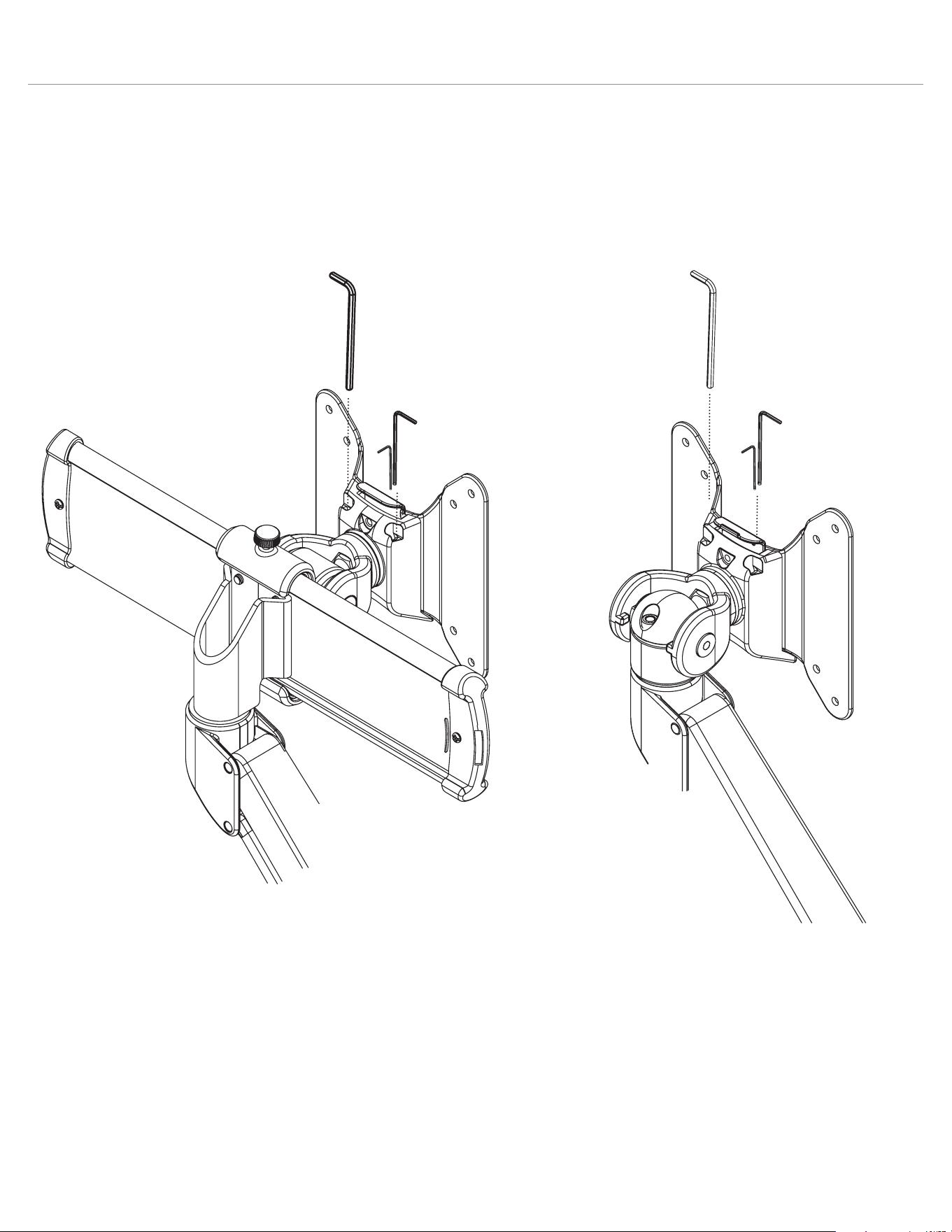
Evolve Attach arms
Each diagram/step may not applicable to your product conguration.
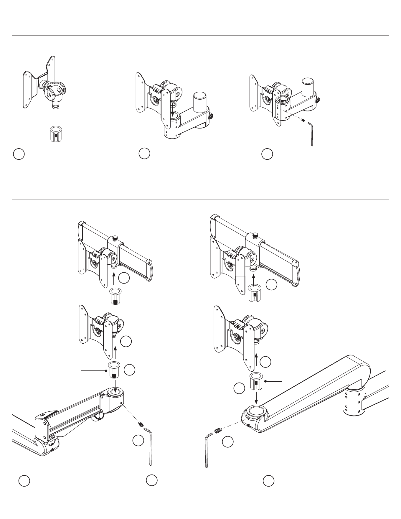
Insert a motion arm or xed arm into a stem arm.
Step 1
Insert motion arm or
xed arm to stem arm.
Step 2
Secure the screw using
the 2mmAllenkey.
1
2
2mm Allen key
(included)
motion arm
1. Rotation tension adjustment
2. Secure arms
2
1
Insert a motion arm or xed arm into a xed arm
Step 1
Insert motion arm or
xed arm to xed arm.
Step 2
Secure the screw using
the 2mmAllenkey.
1
2
2mm Allen key
(included)
motion arm
1. Rotation tension adjustment
2. Secure arms
2
Page 11
Evolve Assembly
Insert VESA to a stem arm.
Step 2
Insert VESA mount to armstem.
Step 3
Secure the screw using the
2mmAllenkey.
Step 1
Attach reducer bushing onto VESA
mount. For detailed instructions on
how to attach the reducer bushing
please reference the slider mount
instructions.
Insert VESA or slider to a motion or xed arm.
small bushing
reducer bushing
Motion arm
Fixed arm
Step 2
Insert slider mount to
motion arm or xed arm.
Step 3
Secure the screw using
the 2mmAllenkey.
Step 1
Attach bushing onto VESA or slider.
1
2
3
1
2
3
1
1
2
3
1
1
2
3
Page 12
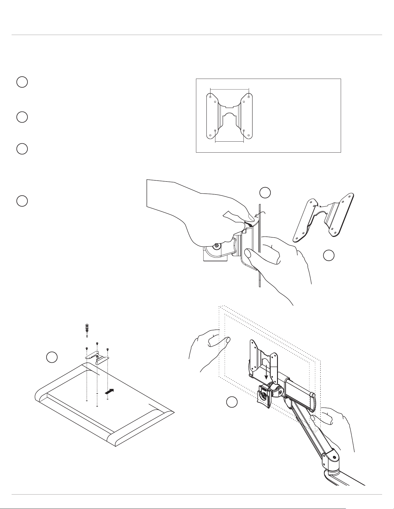
Evolve Attach display
VESA plate is pre-drilled to accommodate varying monitor standards.
Step 3
Place the monitor face down
on a at surface. Align the
VESA plate holes with the
back of the monitor and attach
using the screws provided.
Step 4
With the monitor attached,
reinsert the quick release VESA
plate. Ensure the monitor “clicks”
securely in place.
Step 2
Pull the quick release VESA
plate upward to detach.
Step 1
Pull the tab to release the
quick release VESA plate.
100mm
75mm
Two options of pre-drilled
holes to accommodate
varying monitor standards
monitor
(face down)
3
4
Upward
1
2
3
4
2
1
Page 13
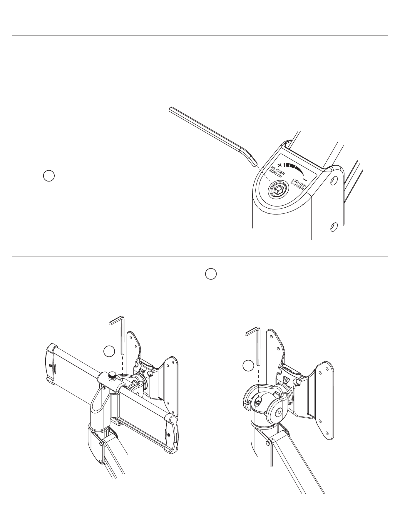
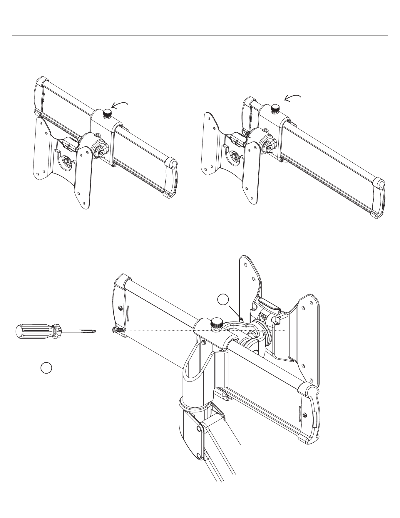
Evolve Adjust tension
Adjusting the tension on your motion arm allows for smooth adjustments.
Tension adjustment supports monitors weighing 6.6 - 17.6 lbs.
Step 2
Use the 4mmAllenkey to adjust the tension to
correspond to the weight of the monitor. Twist
the Allen key in a clockwise direction for heavier
monitors; counterclockwise for lighter monitors.
Adjust mount tilt tension
Adjust motion arm tension
Step 1
Use the 5mmAllenkey
to adjust the tension to
correspond to the weight
of the monitor.
1
2
2
2
Page 14
Evolve Lock features
Optional features
The 180
º
lock-out feature allows
90
º
rotation towards the user, but
prevents 90
º
rotation away from the
user.
Step 1
Fasten the screw with the
2mmAllenkey on the
armstem and then move
the Allen key backward
one circle motion to limit
arm rotation.
180° lock monitor arm
loosen
tighten
1
1
Page 15
Evolve Lock features
If desired, the slider mount can be
secured to prevent the slider
function.
This will lock a monitor in position.
Lock slider plate
lock screw
lock screw
Step 1
To prevent the quick
release function, insert
the screw to the back of
the VESA mount.
Prevent VESA mount quick release
1
1
Page 16
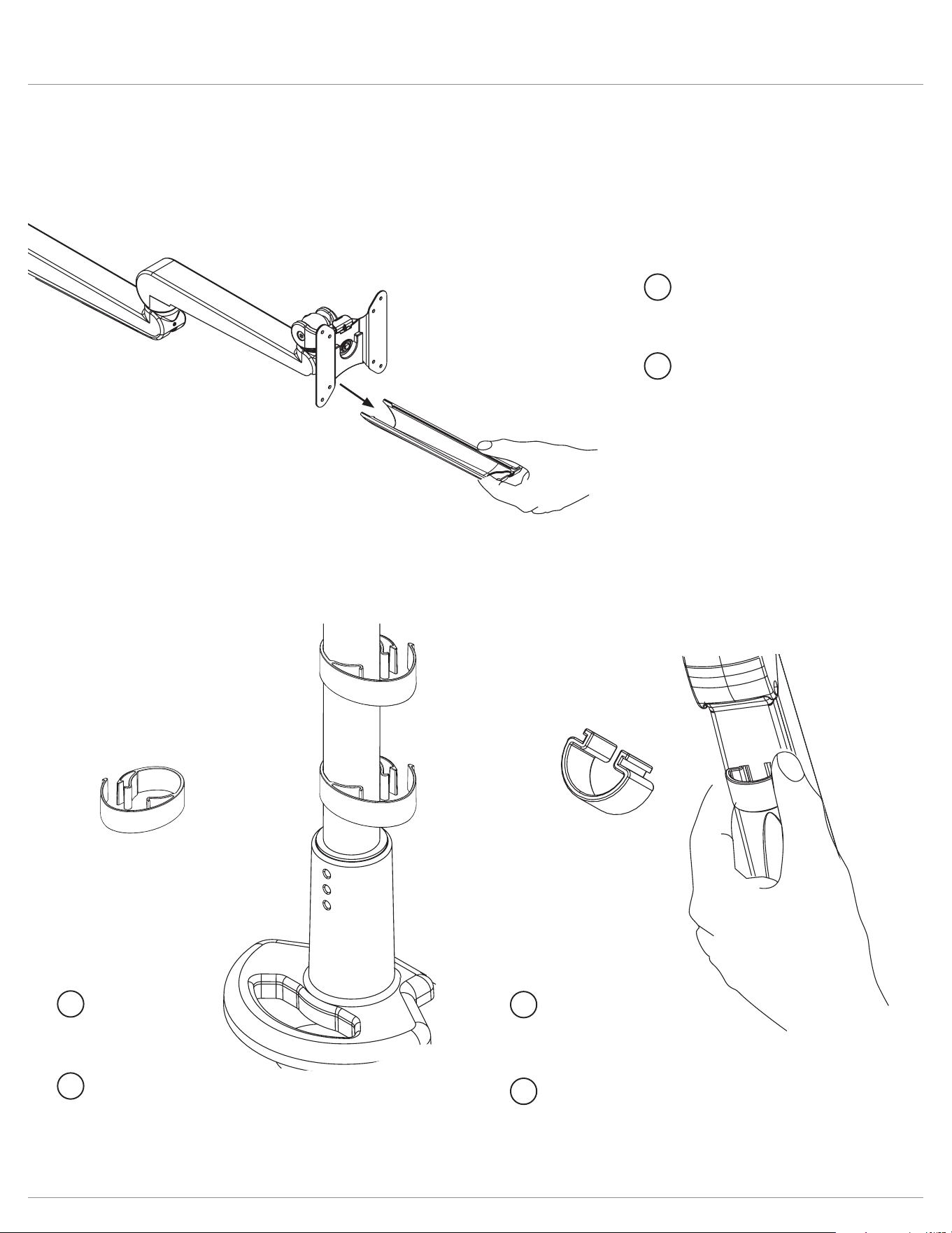
Evolve Cable management
Page 21
Page 20
Step 2
Route cables through
cable clip and reattach
to pole.
Step 2
Route cables through
xed arm tray and
reattach.
Step 1
Slide cable tray outward
to detach from xed arm.
Step 2
Route cables through clip
and reattach.
Step 1
Squeeze clip then pull to
detach the clip from the
motion arm.
Step 1
Detach pole clip
and route cables.
Optional features
pole
clips
1
2
1
2
1
2
Page 17
Evolve Additional features
Page 18
Once assembly is complete, place the
Allen keys in the slots located on the back
side of the VESA and slider mounts.
Insert the two
smaller Allen keys
simultaneously.
Allen key storage


© 2022 Fellowes, Inc. | Part #412822
To contact a Fellowes
®
service representative, call 1-800-833-3746
Warranty information can be found by contacting customer service, your sales representative or by visiting www.fellowes.com