™
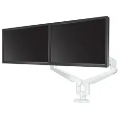
dual monitor arm
ASSEMBLY AND ADJUSTMENT INSTRUCTIONS
IMPORTANT SAFETY INSTRUCTIONS AND WARNINGS
Read before using!
•
•
•
•
•
•
•
•
•
motion arm is used.
•
•
•
•
•
PLEASE REVIEW
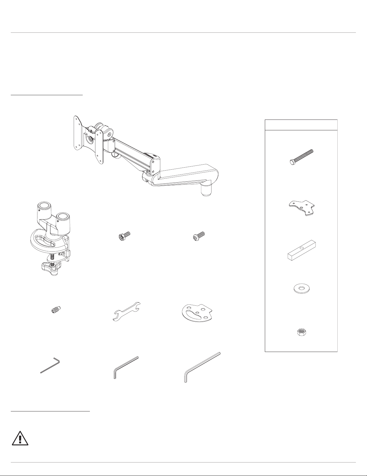
Components and tools
Additional tools required
•
grommet mount plate ()
grommet bar ()
grommet bolt ()
x
3
/8-
grommet bolt washer ()
Mx
9
/16 x
3
/8-
grommet bolt nuts ()
mm allen key ()mm allen key ()mm allen key ()
base assembly ()
Mx
VESA plate screws ()
Mx
VESA locking screws ()
clamp pad ()
mm wrench ()
Mx
180° locking screws ()
monitor arm assembly ()
optional grommet mounting
grommet mount plate ()
grommet bar ()
grommet bolt ()
x
3
/
8
-
grommet bolt washer ()
Mx
9
/16 x
3
/8-
grommet bolt nuts ()
mm allen key ()mm allen key ()mm allen key ()
base assembly ()
Mx
VESA plate screws ()
Mx
VESA locking screws ()
clamp pad ()
mm wrench ()
Mx
180° locking screws ()
monitor arm assembly ()
optional grommet mounting
CAUTION:not
peel and
adhere
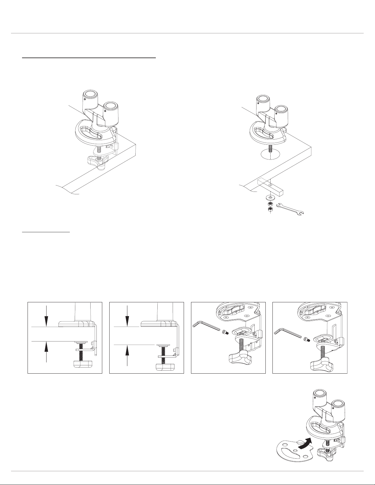
Clamp Method
•
•
CAUTION:
bottom
clamp
assembly
upper attachment
position (standard)
lower attachment
position (optional)
to change: 1) remove
upper attachment screws
2) re-install screws with
clamp in lower position
bottom
clamp
assembly
remove
re-install
upper
attachment
lower
attachment
1.38" – 3"
(35mm – 76mm)
0.6" – 2.2"
(15mm – 56mm)
grommet
method
clamp
method
grommet
method
clamp
method
• Grommet method.
Two Base Assembly Attachment Methods
• Clamp method.
Attach Clamp Pad
•
Install Base Assembly
•
• Proceed to “Install Monitor Arm Assemblies” on page 6.
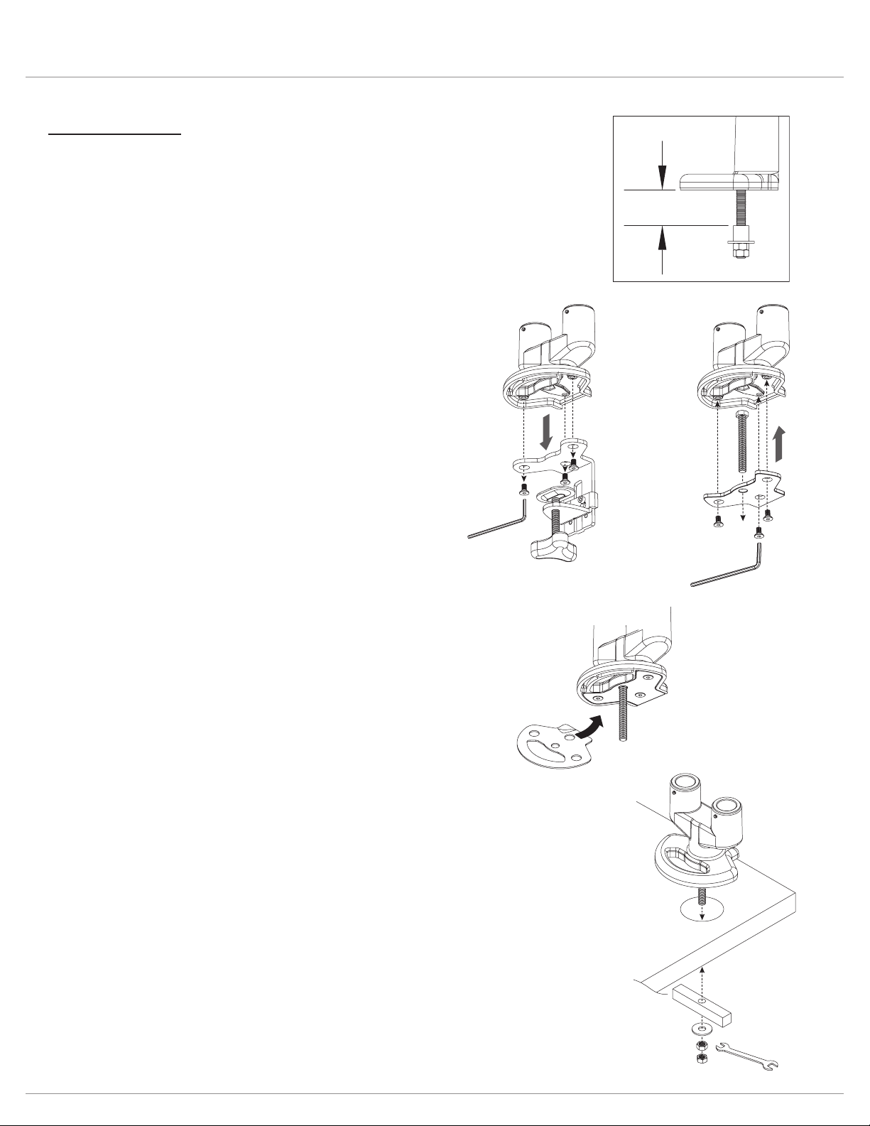
Grommet mount
Grommet Method
.
Remove Clamp Assembly
•
Attach Grommet Assembly
•
•
0.6" – 1.4"
(15mm – 36mm)
remove
clamp
assembly
attach
grommet
assembly
peel and
adhere
base
assembly
grommet
bar
washer
nuts
wrench
Install Base Assembly
•
•
•
—
—
• Proceed to “Install Monitor Arm Assemblies” on page 6.
Attach Clamp Pad
•
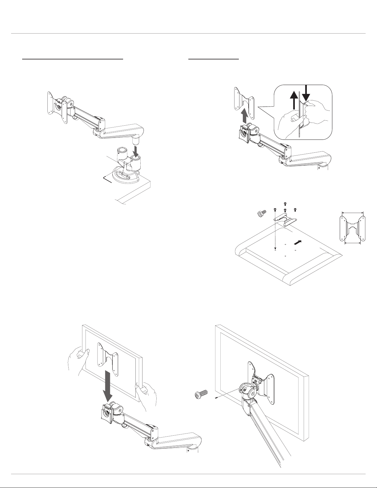
Install Monitor Arm Assemblies
•
•
tighten
set screw
VESA
plate
1.
2.
VESA
plate
screw
VESA plate
3.9"
(100mm)
3"
(75mm)
monitor
(face down)
Upward
Install Monitors
•
•
—
•
— Optional:
VESA
Locking
Screw
(Optional)
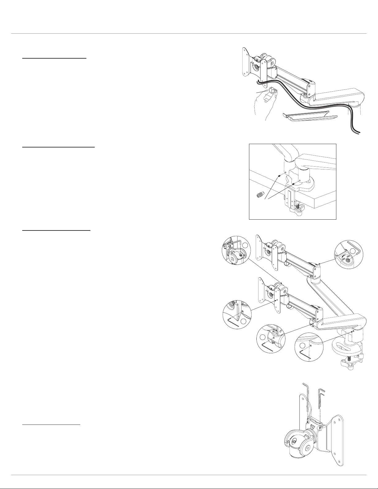
180° Lock-Out Feature
• to
Cable Management
•
•
motion
arm
cable cover
cable
clip
fixed
arm
180° locking
screws
Tension Adjustments
1. Monitor swivel adjustment
—
monitor rotation.
2. Motion arm swivel adjustment
—
motion arm rotation.
3. Fixed arm swivel adjustment
—
4. Monitor tilt adjustment
—
5. Monitor arm weight adjustment
—
—
tension
adjustments
behind
VESA
plate
4
1
5
3
2
store
allen keys
for future
adjustments
Allen Key Storage
•
—

© 2022 Fellowes, Inc. | Part # 412841
To contact a Fellowes
®
service representative, call 1-800-833-3746
Warranty information can be found by contacting customer service, your sales representative or by visiting www.fellowes.com