Loading ...
Loading ...
Loading ...
31-5000572 Rev. 1 27
ENGLISH
INSTALLATION INSTRUCTIONS
Electric Wiring and Applications Cont.
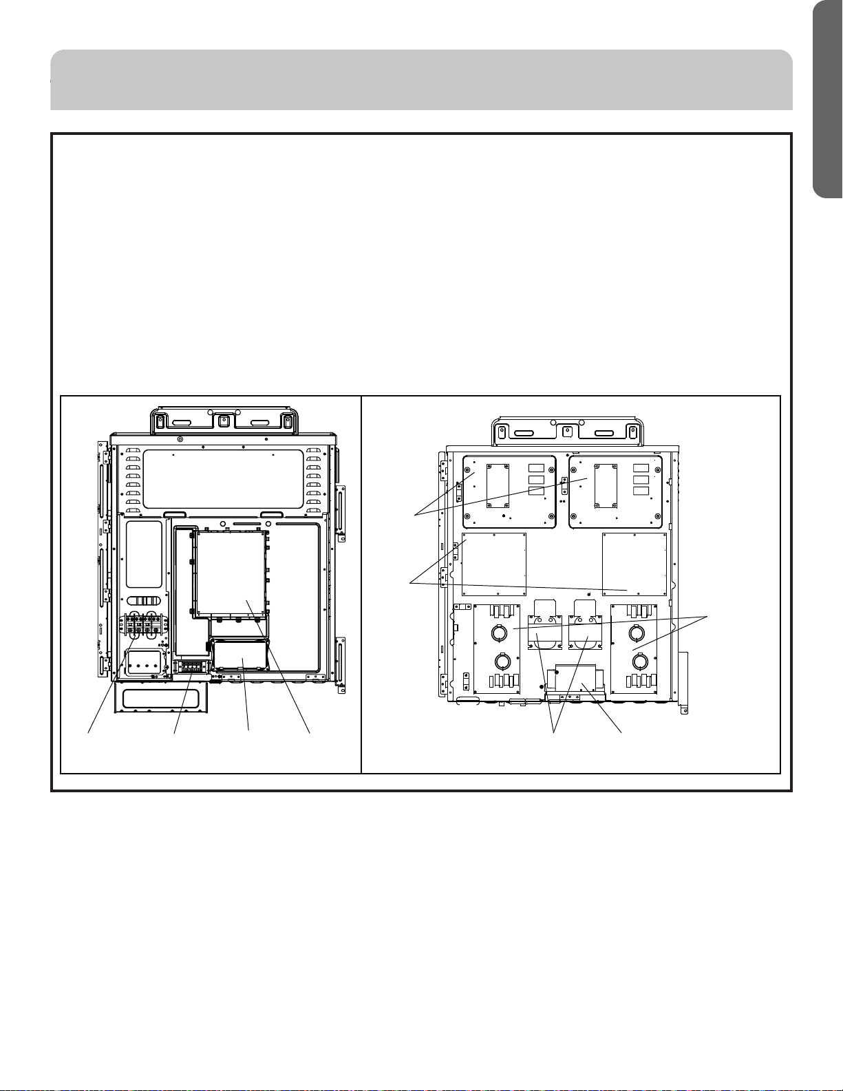
Internal Layout of Electric Box
Outdoor Dip Switch Configuration:
• Main Unit: Main Unit is identified by setting dip switch BM1-7, 8 to zero.
• Function main unit: The outdoor unit, whose priority is set as 0, operates with the highest priority.
• Physical sub unit: By setting the dip switch, the unit number is not 0.
• Functional sub unit: the outdoor without the highest priority of running, the priority class is 1-3.
• Group class setting: physical main unit setting is valid, which can be used for all units. For example, silence, snow-proof,
piping length, etc. setting. Set all kinds of state on the physical main unit as a representative.
• Single class setting: only be used for the single unit, instead of the whole group. For example, sensor backup running,
inverterboard selection etc.
• In the following table, 1 is ON, 0 is OFF.
Power
Terminal
Communication
Terminal
PCB Main Control
Board
Compressor
Drive Module
Capacitor
Plate
Reactor Transformer (only for units
applied voltage with 460V)
Filter Board
Loading ...
Loading ...
Loading ...