Loading ...
Loading ...
Loading ...
MANUEL D’INSTALLATION
INSTALLATION
30
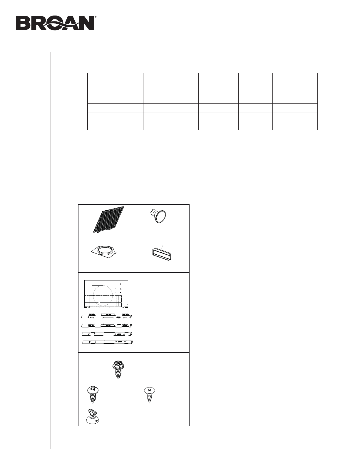
Contenu
Avant de procéder à l’installation, vérifier le contenu de la boîte. Si des articles sont manquants
ou endommagés, contacter le manufacturier.
S’assurer que les articles suivants sont inclus :
Longueurs maximales de conduit recommandées
pour obtenir une efficacité d’évacuation de 80%
LONGUEUR MAXIMALE
DE CONDUIT
DE 3¼ PO X 10 PO,
HORIZONTAL
LONGUEUR MAXIMALE
DE CONDUIT
DE 3¼ PO X 10 PO,
VERTICAL
LONGUEUR
MAXIMALE DE
CONDUIT DE
7 PO ROND
CAPUCHON
DE MUR OU
DE TOIT AVEC
CLAPET
COUDE(S)* DE
(90° ET/OU 45°)
68 pi 51 pi 57 pi 1 0
60 pi 42 pi 42 pi 1 1
51 pi 33 pi 28 pi 1 2
* Coudes standards de rayon interne de 1 po.
NOTE : Il est possible d’utiliser des conduits ronds de 6 po mais l’efficacité de l’évacuation
pourrait être diminuée.
C
L
AB
Apoyar este borde contra la pared de atrás
Place this edge against back wall
VERTICAL EXHAUST
= 3¼” x 10”
= 3¼” x 14”
R
ECTANGULAR
D
UCTING
7” R
OUND
D
UCTING
OR
Use this template for marking; do not attempt to cut out the ducting hole through it.
NOTE: These cutouts are clearance holes; they do not need to be the exact size of ducting.
= 3¼ po x 10 po
= 3¼ po x 14 po
CONDUIT RECTANGULAIRECONDUIT ROND DE 7 PO
OU
= 3¼ pulg. x 10 pulg.
= 3¼ pulg. x 14 pulg.
C
ONDUCTO
RECTANGULAR
C
ONDUCTO
REDONDO
DE 7 PULG.
O
Appuyer ce bord au mur arrière
Utiliser ce gabarit pour marquer vos repères; ne pas tenter de découper
le trou pour le conduit à travers le gabarit.
NOTE : Les découpes incluent le jeu nécessaire à l’installation; elles ne doivent pas
être du format exact des conduits.
Use esta plantilla para crear marcados; no trate de cortar el
agujero del conducto a través de la plantilla.
NOTA: To be translated in Spanish.
MARK WHERE INDICATED
FOR
THE
APPROPRIATE
SIZE
DUCT
OPENING
M
ARQUER
LES
REPÈRES
AUX
ENDROITS
INDIQUÉS
SELON
LE
FORMAT
DE
CONDUIT
UTILISÉ
T
ITLE
TO
BE
TRANSLATED
IN
S
PANISH
Electrical access hole center
A = single blower hood
B = double blower hood
Centre du trou pour fil
d’alimentation électrique
A = hotte ventilateur simple
B = hotte ventilateur double
To be translated in Spanish
Electrical access hole center
A = single blower hood
B = double blower hood
4¼”
10½”
14½”
8”
7½”
C
C
C
Bend template along graduated
scale when installing to framed
cabinet.
Pour une installation sous une
armoire à fond en retrait, utiliser les
lignes pour mesurer l’épaisseur du
décalage causé par le mur de
l’armoire et plier le gabarit en
conséquence.
To be translated in Spanish.
(2) AMPOULES DEL
(4 W, GU10)
(INSTALLÉES SUR LA HOTTE)
(1) VENTOUSE
(1) ADAPTATEUR/VOLET
3¼ PO X 10 PO
* À L’INTÉRIEUR DE LA HOTTE
(1) 7” ROUND
DUCT CONNECTOR
(2) FILTRES À GRAISSES
COMPOSANTS EZ1
(2) S
UPPORTS D’INSTALLATION**
POUR ARMOIRE
AVEC FOND EN RETRAIT
(2) SUPPORTS D’INSTALLATION**
POUR ARMOIRE AVEC FOND RÉGULIER
(1) GABARIT POUR CONDUITS
(IMPRIMÉ SUR LES DEUX CÔTÉS)
** LES SUPPPORTS D’INSTALLATION EZ1 SONT FIXÉS À L’INTÉRIEUR DE LA HOTTE
(1) SAC DE PIÈCES*** COMPRENANT :
(6) VIS À BOIS
À TÊTE RONDE
N° 8 X 5/8 PO
(4) VIS À MÉTAUX
N° 8-18 X 1/2 PO
(6) VIS À BOIS
À TÊTE FRAISÉE
N° 8 X 1/2 PO
*** LE SAC DE PIÈCES SE TROUVE
DERRIÈRE L’ADAPTATEUR/VOLET,
À L’INTÉRIEUR DE LA HOTTE
Loading ...
Loading ...
Loading ...