Loading ...
Loading ...
Loading ...
9
14. MCT Input: Used to transfer signals from
McIntosh products with an MCT connector. Required
for SACD audio.
15. HDMI (ARC) Input: Connect an HDMI cord
here to share control and connectivity with a compat-
ible ARC TV.
Note: The HDMI ARC functionality of the MA8950
is only compatiable with ARC TVs. Other
devices will not work.
16. USB Audio Input: A USB Type-B connector will
go here to receive a digital signal from a computer.
17. Service Port: This USB Type-B port will be used
for service purposes only.
18. Data Ports (1-4): Using 3.5mm data cables (see
next section), you can plug other McIntosh devices
into these ports and control them with your McIntosh
Remote Control.
19. RS232 Port: Using a 3.5mm-to-DB9 cable
(see next section), you can connect the device to a
computer or another controller device through here.
20. IR In Port: Connect an external IR sensor here
with a 3.5mm connector (see next section).
21. Trigger Ports (1 and 2): Connecting external
components to these ports via a 3.5mm connection
(see next section) will allow you to send a signal to
turn those devices On or Off from a signal sent by the
MA8950.
22. Passthru Input: Connecting other devices with
a 3.5mm connector (see next section), in addition to
their main connection, will enable Passthru Mode
when enabled in the Setup Menu (see Page 13),
producing unaltered audio.
23. Main Output Control Port: McIntosh devices
can turn each other On and Off when connected via a
3.5mm connector (see next section) to these ports.
Connector and Cable Information
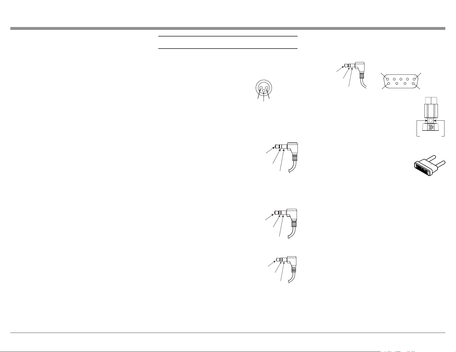
XLR Connectors
Below is the Pin configuration for the XLR Balanced
Input Connectors on the MA8950. Refer to the dia-
gram for connection:
PIN 1: Shield/Ground
PIN 2: + Output
PIN 3: - Output
Power Control and Trigger Connectors
The Power Control Trigger Output Jacks send and
Passthru Input Jack receives Power
On/Off Signals (+12 volt/0 volt)
when connected to other McIntosh
Components. An additional connec-
tion is for controlling the illumina-
tion of the Power Output Meters
on McIntosh Power Amplifiers. A
3.5mm stereo mini phone plug is
used for connection to the Power Control, Trigger and
Passthru Outputs.
Data Port Connectors
The Data Out Ports send Remote
Control Signals to Source Compo-
nents. A 3.5mm stereo mini phone
plug is used for connection.
IR IN Port Connectors
The IR IN Port also uses a 3.5mm
stereo mini phone plug and allows
the connection of other brand IR
Receivers to the MA8950.
RS232-C Data Port Cable
The RS232 Data Cable is a 3.5mm stereo mini phone
plug to a sub miniature DB 9 connector:
Output Terminal Connector
When cables with spade lugs are used
for Loudspeaker Connection, the spade
lugs need an opening of at least 3/10 inch
(7.6m m)
McIntosh Plug-In Jumper Connector
(x2 Included)
The MA8950 utilizes two phono style
Plug-In Jumpers to connect the Preampli-
fier Output to the Power Amplifier Input.
Note: Additional or replacement Jumper Connectors can
be obtained from the McInotsh Parts Department
under Part No. 117781.
PIN 1
PIN 2
PIN 3
Power
Control
Meter
Illumination
Control
Ground
Main, Trig 1&2
and Pass-Thru
Data
Signal
N/C
Data
Ground
IR Data
Control
Ground
N/C
PIN 1
PIN 6
PIN 5
PIN 9
Data In
(DB9-pin2)
Ground
(DB9-pin5)
Data Out
(DB9-pin3)
DB9
(male connector)
3/10 of an inch
(7.6millimeters)
Loading ...
Loading ...
Loading ...