Loading ...
Loading ...
Loading ...
Well Pipe Installation
SUCTIONJ
PIPE
PRIMING PLUG _ CHECK
PRIMING TEE _VALVE
fl STEEL
DING WATER I I
-P4HI -- LEVEL I I
I ] (PUMPOFF) [ I
I I II DRAWDOWNWATER I I
(PUMP ON) coD#/VlEN G
I III f EI -WEL,
_1 @ST 5 FEET _ POINT
II DRIVEN POINT
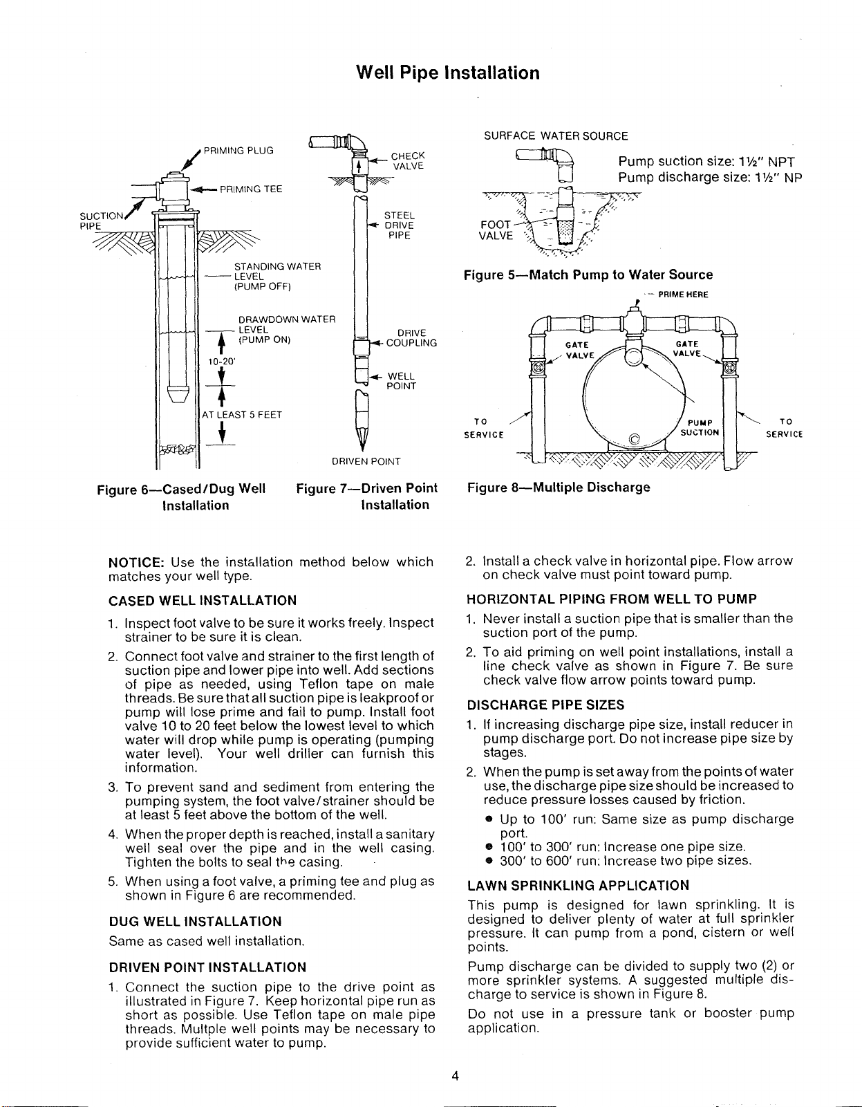
Figure 6--Cased/Dug Well
Installation
Figure 7--Driven Point
Installation
SURFACE WATER SOURCE
Pump suction size: 11/2"NPT
Pump discharge size: 11/2"NP
VALVE "- . ""
!ALVE __"
Figure 5--Match Pump to Water Source
--- PRIME HERE
TO
SERVICE
TO
SERVICE
Figure 8--Multiple Discharge
NOTICE: Use the installation method below which
matches your well type.
CASED WELL INSTALLATION
1.
2
.
Inspect foot valve to be sure it works freely. Inspect
strainer to be sure it is clean.
Connect foot valve and strainer to the first length of
suction pipe and lower pipe into well. Add sections
of pipe as needed, using Teflon tape on male
threads. Be sure that all suction pipe is leakproof or
pump will lose prime and fail to pump. Install foot
valve 10 to 20 feet below the lowest level to which
water will drop while pump is operating (pumping
water level). Your well driller can furnish this
information.
To prevent sand and sediment from entering the
pumping system, the foot valve/strainer should be
at least 5 feet above the bottom of the well.
4. When the proper depth is reached, install a sanitary
well seal over the pipe and in the well casing.
Tighten the bolts to seal the casing.
5. When using a foot valve, a priming tee and plug as
shown in Figure 6 are recommended.
DUG WELL INSTALLATION
Same as cased well installation.
DRIVEN POINT INSTALLATION
1. Connect the suction pipe to the drive point as
illustrated in Figure 7. Keep horizontal pipe run as
short as possible. Use Teflon tape on male pipe
threads. Multple well points may be necessary to
provide sufficient water to pump.
2. Install a check valve in horizontal pipe. Flow arrow
on check valve must point toward pump.
HORIZONTAL PIPING FROM WELL TO PUMP
1. Never install a suction pipe that is smaller than the
suction port of the pump.
2. To aid priming on well point installations, install a
line check valve as shown in Figure 7. Be sure
check valve flow arrow points toward pump.
DISCHARGE PIPE SIZES
1.
.
If increasing discharge pipe size, install reducer in
pump discharge port. Do not increase pipe size by
stages.
When the pump is set away from the points of water
use, the discharge pipe size should be increased to
reduce pressure losses caused by friction•
e Up to 100' run: Same size as pump discharge
port•
• 100' to 300' run: Increase one pipe size.
• 300' to 600' run: Increase two pipe sizes.
LAWN SPRINKLING APPLICATION
This pump is designed for lawn sprinkling. It is
designed to deliver plenty of water at full sprinkler
pressure. It can pump from a pond, cistern or well
points.
Pump discharge can be divided to supply two (2) or
more sprinkler systems. A suggested multiple dis-
charge to service is shown in Figure 8.
Do not use in a pressure tank or booster pump
application.
Loading ...
Loading ...
Loading ...