

Owner's Manual
GARDEN TRACTOR
23.0 HP, 50" Mower
ElectricStart
6 Speed
Model No.
917.275033
This product has a low emission engine which operates
I_ differently from previously built engines. Before start the en-you
gine, read and understand this Owner's Manual,
CAUTION:
Read and follow all Safety
Rules and Instructions before
operating this equipment.
For answers to your questions
about this product, Call:
1-800-659-5917
Sears Craftsman Help Line
5 am - 5 pm, Mon - Sat
SEARS, ROEBUCKAND CO., HOFFMAN ESTATES, IL60179 U.S.A.
Visit our Craftsman website:www.sears.com/craftsman

Warranty ............................................... 2
Safety Rules ......................................... 3
Product Specifications .......................... 6
Assembly/Pre-Operation ...................... 8
Operation ............................................ 12
Maintenance Schedule ...................... 18
Maintenance ....................................... 18
Service and Adjustments .................... 22
Storage ............................................... 29
Troubleshooting ................................. 30
Repair Parts ........................................ 34
Sears Service ...................... Back Cover
LIMITED TWO YEAR WARRANTY ON CRAFTSMAN RIDING EQUIPMENT PARTS
For two (2) years from the date of purchase, if this Craftsman Riding Equipment is
maintained, lubricated and tuned up according to the instructions in the owner's
manual, Sears will repair or replace, free of charge, any parts found to be defective in
material or workmanship. Warranty service is available free of charge by returning your
Craftsman riding equipment to your nearest Sears Service Center. In-home warranty
service is available but a trip charge will apply. This warranty applies only while this
product is in the United States.
This Warranty does not cover:
• Expendable items which become worn during normal use, such as blades, spark
plugs, air cleaners, belts and oil filters.
• Tire replacement or repair caused by puncture_ from outside objects, such as nails,
thoms, stumps, or glass.
• Repairs necessary because of operator abuse, including but not limited to, damage
caused by towing objects beyond the capability of the riding equipment, impacting
objects that bend the frame or crankshaft, or over speeding the engine.
• Repairs necessary because of operator negligence, including but not limited to,
electrical and mechanical damage caused by improper storage, failure to use the
proper grade and amount of engine oil, failure to keep the deck clear of flammable
debris, or the failure to maintain the eqL,,_:,=ent according to the instructions con-
tained in the owner's manual.
• Engine (fuel system) cleaning or repairs caused by fuel determined to be contami-
nated or oxidized (stale). In general, fuel should be used within thirty (30) days of its
purchase date.
• Riding equipment used for commercial or rental purposes. A product is "used for
commemial purpose" if is used for any purpose other than single family household
dwellings or in usage where profit is made.
LIMITED 90 DAY WARRANTY ON BATTERY
For ninety (90) days from date of purchase, if any battery included with this riding
equipment proves defective in material or workmanship and our testing determines the
battery will not hold a charge, Sears will replace the battery at no charge. Warranty
service is available free of charge by retuming your Craftsman riding equipment to
your nearest Sears Service Center. In-home warranty service is available but a trip
charge will apply. This warranty applies only while this product is in the United States.
TO LOCATE THE NEAREST SEARS SERVICE CENTER OR TO SCHEDULE IN-HOME
WARRANTY SERVICE, SIMPLY CONTACT SEARS AT 1-800-4-MY-HOME
This Warranty gives you specific legal rights, and you may also have other rights which
may vary from state to state.
Sears, Roebuck and Co., D/817 WA, Hoffman Estates, IL 60179
,
IMPORTANT: This cutting machine is capable of amputating hands and feet and
throwing, objects. Failure to observe the following safety instructions could result in
serious injury or death.
4UkLook for this symbol to point out
important safety precautions. It means
CAUTION!i! BECOMEALERTt!! YOUR
SAFETY IS INVOLVED.
CAUTION: In order to prevent
accidental starting when setting up,
transporting, adjusting or making repairs,
always disconnect spark plug wire and
place wire where it cannot contact spark
plug.
i
_, CAUTION: Do not coast down a hill
in neutral, you may lose control of the
tractor.
,_ CAUTION: Tow only the attachments
that are recommended by and comply
with specifications of the manufacturer of
your tractor. Use common sense when
towing. Operate only at the lowest
possible speed when on a slope. Too
heavy of a load, while on a slope, is
dangerous. Tires can lose traction with
the ground and cause you to lose control
of your tractor.
i
_IWARNING: Engine exhaust, some of
its constituents, and certain vehicle
components contain or emit chemicals
known to the State of Califomia to cause
cancer and birth defects or other repro-
ductive harm.
WARNING: Battery posts, terminals
and related accessodes contain lead
and lead compounds, chemicals known
to the State of California to cause cancer
and birth defects or other reproductive
harm. Wash hands after handling,
I. GENERAL OPERATION
• Read, understand, and follow all
instructions in the manual and on the
machine before starting.
• Only allow responsible adults, who are
familiar with the instructions, to operate
the machine.
• Clear the area of objects such as rocks,
toys, wire, etc., which could be picked
up and thrown by the blade.
• Be sure the area is clear of other people
before mowing. Stop machine if anyone
enters the area.
• Never carry passengers.
• Do not mow in reverse unless absolutely
necessary. Always look down and
behind before and while backing.
• Be aware of the mower discharge
direction and do not point it at anyone.
Do not operate the mower without either
the entire grass catcher or the guard in
place.
• Slow down before turning.
• Never leave a running machine
unattended. Always tum off blades, set
parking brake, stop engine, and remove
keys before dismounting.
•Tum off blades when not mowing.
• Stop engine before removing grass
catcher or unclogging chute.
• Mow only in daylight or good artiticial
light.
• Do not operate the machine while under
the influence of alcohol or drugs.
• Watch for traffic when operating near or
crossing roadways.
• Use extra care when loading or unload-
ing the machine into a trailer or truck.
• Data indicates that operators, age 60
years and above, are involved in a large
percentage of riding mower-related
injuries. These operators should
evaluate their ability to operate the riding
mower safely enough to protect them-
selves and others from serious injury.
• Keep machine free of grass, leaves or
other debris build-up which can touch
hot exhaust / engine parts and bum. Do
not allow the mower deck to plow leaves
or other debris which can cause build-
up to occur. Clean any oil or fuel
spillage before operating or storing the
machine. Allow machine to cool before
storage.
II. SLOPE OPERATION
Slopes are a major factor related to loss-of-
control and tipover accidents, which can re-
suit in severe injury or death. All slopes
require extra caution. If you cannot back up
the slope or if you feel uneasy on it, do not
mow it.
3
DO:
• Mow up and down slopes, not across.
• Remove obstacles such as rocks, tree
limbs, etc.
• Watch for holes, ruts, or bumps. Uneven
terrain could overtum the machine. Tall
grass can hide obstacles.
• Use slow speed. Choose a low gear so
that you will not have to stop or shift
while on the slope.
• Follow the manufacturer's recommenda-
tions for wheel weights or counter-
weights to improve stability.
• Use extra care with grass catchers or
other attachments. These can change
the stability of the machine.
• Keep all movement on the slopes slow
and gradual. Do not make sudden
changes in speed or direction.
• Avoid starting or stopping on a slope. If
tires lose traction, disengage the blades
and proceed slowly straight down the
slope.
DO NOT:
• Do not turn on slopes unless necessary,
and then, tum slowly and gradually
downhill, if possible.
• Do not mow near drop-offs, ditches, or
embankments. The mower could
suddenly turn over if a wheel is over the
edge of a cliff or ditch, or if an edge
caves in.
• Do not mow on wet grass. Reduced
traction could cause sliding.
• Do not tty to stabilize the machine by
putting your foot on the ground.
• Do not use grass catcher on steep
slopes.
IlL CHILDREN
Tragic accidents can occur if the operator
is not alert to the presence of children.
Children are often attracted to the
machine and the mowing activity. Never
assume that children will remain where
you last saw them.
• Keep children out of the mowing area
and under the watchful care of another
responsible adult.
• Be alert and turn machine oft if children
enter the area.
• Before and when backing, look behind
and down for small children.
• Never carry children. They may fall off
and be sedously injured or interfere
with safe machine operation.
• Never allow children to operate the
machine.
• Use extra care when approaching blind
corners, shrubs, trees, or other objects
that may obscure vision.
IV. SERVICE
• Use extra care in handling gasoline
and other fuels. They are flammable
and vapors are explosive.
-Use only an approved container.
- Never remove gas cap or add fuel
with the engine running. Allow
engine to cool before refueling. Do
not smoke.
- Never refuel the machine indoors.
- Never store the machine or fuel
container inside where there is an
open flame, such as a water heater.
• Never run a machine inside a closed
area.
• Keep nuts and bolts, especially blade
attachment bolts, tight and keep
equipment in good condition.
• Never tamper with safety devices.
Check their proper operation regulady.
• Keep machine free of grass, leaves, or
other debris build-up. Clean oil or fuel
spillage. Allow machine to cool before
storing.
• Stop and inspect the equipment if you
stdke an object. Repair, if necessary,
before restarting.
• Never make adjustments or repairs
with the engine running.
• Grass catcher components are subject
to wear, damage, and detedoration,
which could expose moving parts or
allow objects to be thrown. Frequently
check components and replace with
manufacturer's recommended parts,
when necessary.
• Mower blades are sharp and can cut.
Wrap the blade(s) or wear gloves, and
use extra caution when servicing them.
• Check brake operation frequently.
Adjust and service as required.
4
• Be sure the area is clear of other
people before mowing. Stop machine if
anyone enters the area.
• Never carry passengers or children
even with the blades off.
• Do not mow in reverse unless abso-
lutely necessary. Always look down
and behind before and while backing.
• Never carry children. They may fall off
and be seriously injured or interfere
with safe machine operation.
• Keep children out of the mowing area
and under the watchful care of another
responsible adult.
• Be alert and turn machine off if children
enter the area.
• Before and when backing, look behind
and down for small children.
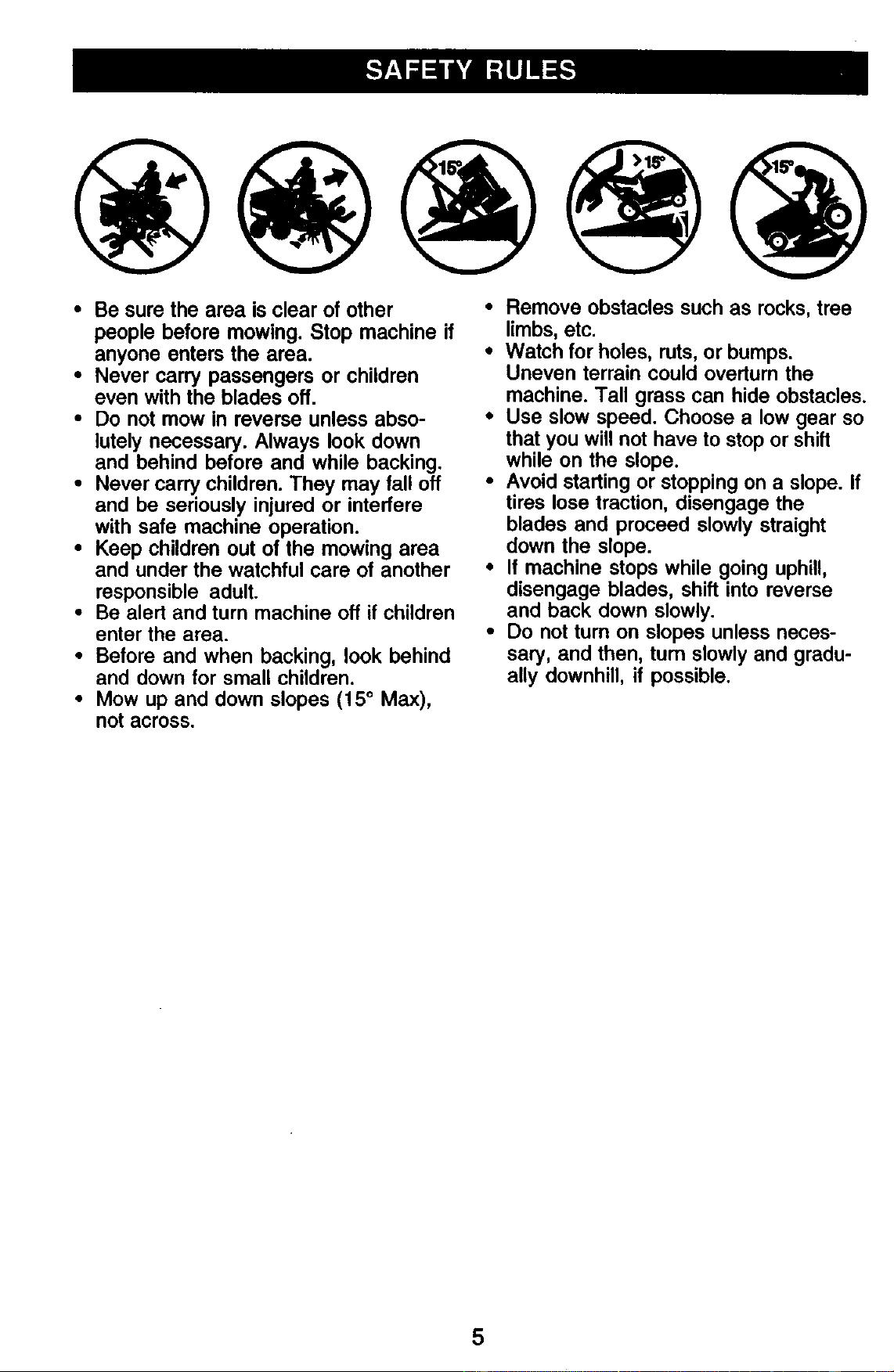
• Mow up and down slopes (15 ° Max),
not across.
• Remove obstacles such as recks, tree
limbs, etc.
• Watch for holes, ruts, or bumps.
Uneven terrain could overturn the
machine. Tall grass can hide obstacles.
• Use slow speed. Choose a low gear so
that you will not have to stop or shift
while on the slope.
• Avoid starting or stopping on a slope. If
tires lose traction, disengage the
blades and proceed slowly straight
down the slope.
• If machine stops while going uphill,
disengage blades, shift into reverse
and back down slowly.
• Do not turn on slopes unless neces-
sary, and then, turn slowly and gradu-
ally downhill, if possible.
5
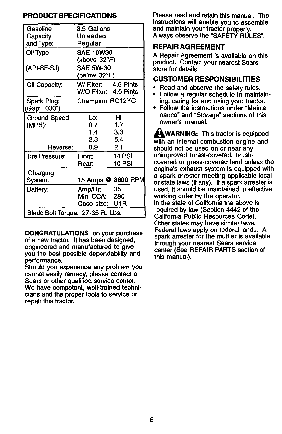
PRODUCT SPECIFICATIONS
Gasoline 3.5 Gallons
Capacity Unleaded
and Type: Regular
Oil Type SAE 10W30
(above 32°F)
'API-SF-SJ): SAE 5W-30
(below 32°F)
Oil Capacity: W/Filter: 4.5 Pints
W/O Filter:. 4.0 Pints
Spark Plug: Champion RC12YC
CGap: .030")
Ground Speed Lo: Hi:
MPH): 0.7 1.7
1.4 3.3
2.3 5.4
Reverse: 0.9 2.1
Tire Pressure: Front: 14 PSI
Rear: 10 PSI
Charging
System: 15 Amps @ 3600 RPM
Battery: Amp/Hr: 35
Min. CCA: 280
Case size: U1R
Blade Bolt Torque: 27-35 Ft. Lbs.
CONGRATULATIONS on your purchase
of a new tractor. It has been designed,
engineered and manufactured to give
you the best possible dependability and
performance.
Should you expedence any problem you
cannot easily remedy, please contact a
Sears or other qualified service center.
We have competent, well-trained techni-
cians and the proper tools to service or
repair this tractor.
Please read and retain this manual. The
instructions will enable you to assemble
and maintain your tractor properly.
Always observe the =SAFETY RULES".
REPAIR AGREEMENT
A Repair Agreement is available on this
product, Contact your nearest Sears
store for details.
CUSTOMER RESPONSIBILITIES
• Read and observe the safety rules.
• Follow a regular schedule in maintain-
ing, caring for and using your tractor.
• Follow the instructions under =Mainte-
nance" and =Storage" sections of this
owner's manual.
_WARNING: This tractor is equipped
with an intemal combustion engine and
should not be used on or near any
unimproved forest-covered, brush-
covered or grass-covered land unless the
engine's exhaust system is equipped with
a spark arrester meeting applicable local
or state laws (if any). If a spark arrester is
used, it should be maintained in effective
working order by the operator.
In the state of California the above is
required by law (Section 4442 of the
California Public Resources Code).
Other states may have similar laws.
Federal laws apply on federal lands. A
spark arrester for the muffler is available
through your nearest Sears service
center (See REPAIR PARTS section of
this manual).
6
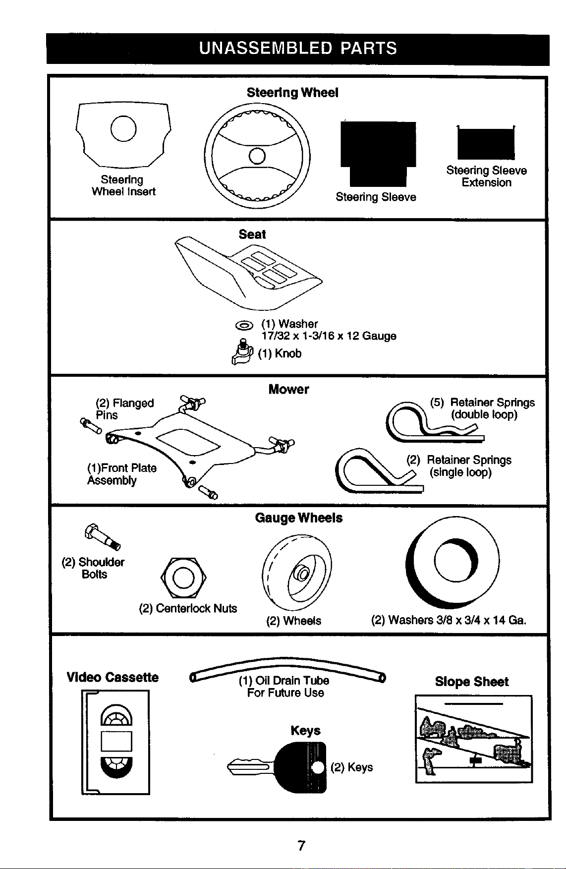
Steering
Wheel Insert
Steering Wheel
Steedng Sleeve
Steedng Sleeve
Extension
Seat
<:_ (1)Washer
17/32 x 1-3/16 x 12 Gsuge
_(1) Knob
(2) Flanged
ins
(1)Front Plate
Assembly
Mower
(5) Retainer Springs
loop)
(2) Retainer Springs
i (single loop)
(2) Shoulder
Bolts
©
(2) Centerlock Nuts
(2) Wheels (2) Washers 3/8 x 314 x 14 Ga.
Video Cassette
m,
F-7
"-'t
For Future Use
Keys
(2) Keys
Slope Sheet
7
Your new tractor has been assembled at the factory with the exception of those parts
left unassembled for shipping purposes. To ensure safe and proper operation of your
tractor all parts and hardware you assemble must be tightened securely. Use the
correct tools as necessary to insure proper tightness. Review the video cassette before
you begin.
TOOLS REQUIRED FOR ASSEMBLY
A socket wrench set will make assembly
easier. Standard wrench sizes you need
are listed below.
(1) 9/16" wrench (1) Pliers
(1) 1/2"wrench (1) Utility knife
(1) 3/4" socket with
drive ratchet
(1) Tire pressure gauge
When right or left hand is mentioned in
this manual, it means, from your point of
view, when you are in the operating
position (seated behind the steering
wheel).
TO REMOVE TRACTOR FROM
CARTON
UNPACK CARTON
1. Remove all accessible loose parts
and parts boxes from carton.
2. Cut, from top to bottom, along lines on
all four corners of carton, and lay
panels flat.
3. Remove mower and packing materi-
als.
4. Check for any additional loose parts
or cartons and remove.
BEFORE REMOVING TRACTOR
FROM SKID
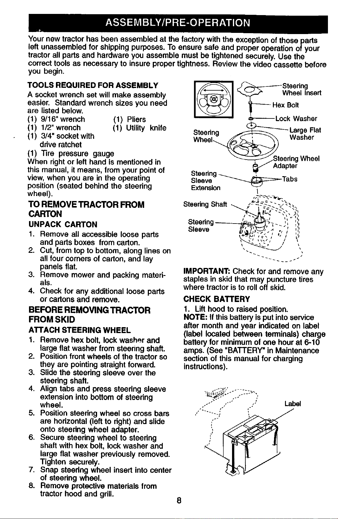
ATTACH STEERING WHEEL
1. Remove hex bolt, lock washer and
large flat washer from steering shaft.
2. Position front wheels of the tractor so
they are pointing straight forward.
3. Slide the steedng sleeve over the
steering shaft.
4. Align tabs and press steedng sleeve
extension into bottom of steering
wheel.
5. Position steering wheel so cross bars
are horizontal (left to dght) and slide
onto steedng wheel adapter.
6. Secure steedng wheel to steering
shaft with hex bolt, lock washer and
large flat washer previously removed.
Tighten securely.
7. Snap steedng wheel insert into center
of steering wheel.
8. Remove protective materials from
tractor hood and gdll.
_.-_ Wheel Insed
_---- Hex Bolt
•=_------- Lock Washer
Steering _ Large Flat
Wheel_../_ Washer
"_-_AStceae;; 7 Whee,
Steering_ .
Sleeve __:=::_-Tabs
Extension I
Steering Shaft ,- -,---_--_-;. -_.
Steedng ,-=,. ",-- , ,
• "/I/] I I _j I Iii
Sleeve _, , ,
.,,,,
L,_,/J _"1 I I I
<"-_l 1/,._ / "* I _/
_ \l Ik_/# / I
IMPORTANT: Check for and remove any
staples in skid that may puncture tires
where tractor is to roll off skid.
CHECK BATTERY
1. Lift hood to raised position.
NOTE: If this battery is put into service
after month and year indicated on label
(label located between terminals) charge
battery for minimum of one hour at 6-10
amps. (See "BATTERY" in Maintenance
section of this manual for charging
instructions).
." t.
÷%_..
Label
8
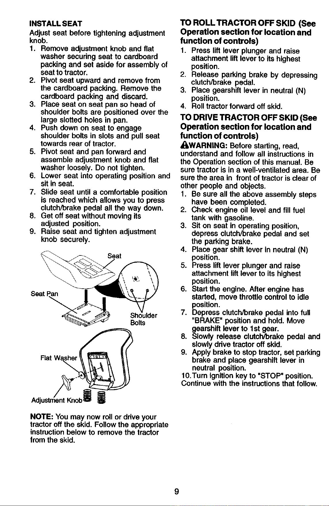
INSTALL SEAT
Adjust seat before tightening adjustment
knob.
1. Remove adjustment knob and flat
washer secudng seat to cardboard
packing and set aside for assembly of
seat to tractor.
2. Pivot seat upward and remove from
the cardboard packing. Remove the
cardboard packing and discard.
3. Place seat on seat pan so head of
shoulder bolts are positioned over the
large slotted holes in pan.
4. Push down on seat to engage
shoulder bolts in slots and pull seat
towards rear of tractor.
5. Pivot seat and pan forward and
assemble adjustment knob and flat
washer loosely. Do not tighten.
6. Lower seat into operating position and
sit in seat.
7. Slide seat until a comfortable position
is reached which allows you to press
clutch/brake pedal all the way down.
8. Get off seat without moving its
adjusted position.
9. Raise seat and tighten adjustment
knob securely.
Seat
Seat
Flat W_r_
Adjustn ert_Knob
Sh
Bolts
|
NOTE: You may now roll or ddve your
tractor off the skid. Follow the apprepriate
instruction below to remove the tractor
from the skid.
TO ROLL TRACTOR OFF SKID (See
Operation section for location and
function of controls)
1. Press lift lever plunger and raise
attachment lift lever to its highest
position.
2. Release parking brake by depressing
clutch/brake pedal.
3. Place gearshift lever in neutral (N)
position.
4. Roll tractor forward off skid.
TO DRIVE TRACTOR OFF SKID (See
Operation section for location and
function of controls)
_kWARNING: Before starting, read,
understand and follow all instructions in
the Operation section of this manual. Be
sure tractor is in a well-ventilated area. Be
sure the area in front of tractor is clear of
other people and objects.
1. Be sure all the above assembly steps
have been completed.
2. Check engine oil level and fill fuel
tank with gasoline.
3. Sit on seat in operating position,
depress clutch/brake pedal and set
the parking brake.
4. Place gear shift lever in neutral (N)
position.
5. Press lift lever plunger and raise
attachment lift lever to its highest
position.
6. Start the engine. After engine has
started, move throttle control to idle
position.
7. Depress clutch/brake pedal into full
"BRAKE" position and hold. Move
gearshift lever to 1st gear.
8. Slowly release clutch/brake pedal and
slowly drive tractor off skid.
9. Apply brake to stop tractor, set parking
brake and place gearshift lever in
neutral position.
10.Turn ignition key to "STOP" position.
Continue with the instructions that follow.
9
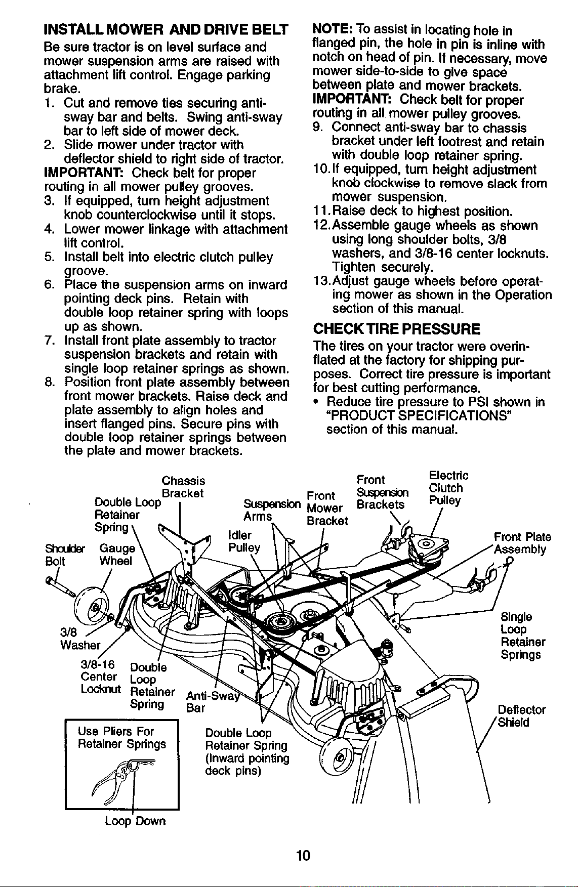
INSTALL MOWER AND DRIVE BELT
Be sure tractor is on level surface and
mower suspension arms are raised with
attachment lift control. Engage parking
brake.
1. Cut and remove ties securing anti-
sway bar and belts. Swing anti-sway
bar to left side of mower deck.
2. Slide mower under tractor with
deflector shield to dght side of tractor.
IMPORTANT: Check belt for proper
routing in all mower pulley grooves.
3. If equipped, turn height adjustment
knob counterclockwise until it stops.
4. Lower mower linkage with attachment
lift control.
5. Install belt into electric clutch pulley
groove.
6. Place the suspension arms on inward
pointing deck pins. Retain with
double loop retainer spdng with loops
up as shown.
7. Install front plate assembly to tractor
suspension brackets and retain with
single loop retainer springs as shown.
8. Position front plate assembly between
front mower brackets. Raise deck and
plate assembly to align holes and
insert flanged pins. Secure pins with
double loop retainer springs between
the plate and mower brackets.
NOTE: To assist in locating hole in
flanged pin, the hole in pin is inline with
notch on head of pin. If necessary, move
mower side-to-side to give space
between plate and mower brackets.
IMPORTANT: Check belt for proper
routing in all mower pulley grooves.
9. Connect anti-sway bar to chassis
bracket under left footrest and retain
with double loop retainer spring.
10. If equipped, turn height adjustment
knob clockwise to remove slack from
mower suspension.
11 .Raise deck to highest position.
12.Assemble gauge wheels as shown
using long shoulder bolts, 3/8
washers, and 3/8-16 center Iocknuts.
Tighten securely.
13.Adjust gauge wheels before operat-
ing mower as shown in the Operation
section of this manual.
CHECK TIRE PRESSURE
The tires on your tractor were overin-
flated at the factory for shipping pur-
poses. Correct tire pressure is important
for best cutting performance.
• Reduce tire pressure to PSI shown in
=PRODUCT SPECIFICATIONS"
section of this manual.
Chassis
Bracket
Double Loop
Retainer
Shoukbr
Bolt Wheel
Front
Suspension Mower
Arms Bracket
Idler
Front Electric
Suspension Clutch
Brackets Pulley
Front Plate
3/8
Washer
3/8-16 Double
Center Loop
Locknut Retainer
Spdng
Use Pliers For
Retainer Springs
Loop Down
Bar
Double Loop
Retainer Spring
(Inward pointing
deck pins)
Single
Loop
Retainer
Springs
Deflector
10

CHECK MOWER LEVELNESS
For best cutting results, mower should be
propedy leveled. See "TO LEVEL
MOWER HOUSING" in the Service and
Adjustments section of this manual.
CHECK FOR PROPER POSITION OF
ALL BELTS
See the figures that are shown for
replacing motion, mower drive, and
mower blade drive belts in the Service
and Adjustments section of this manual.
Verify that the belts are muted correctly.
CHECK BRAKE SYSTEM
After you learn how to operate your
tractor, check to see that the brake is
propedy adjusted. See "TO ADJUST
BRAKE" in the Service and Adjustments
section of this manual.
/ CHECKLIST
Before you operate your new tractor, we
wish to assure that you receive the best
performance and satisfaction from this
Quality Product.
Please review the following checklist:
•/All assembly instructions have been
completed.
,/No remaining loose parts in carton.
/ Battery is properly prepared and
charged. (Minimum 1 hour at 6 amps).
•/ Seat is adjusted comfortably and
tightened securely.
,/All tires are propedy inflated. (For
shipping purposes, the tires were
ovednflated at the factory).
,/Be sure mower deck is properly leveled
side-to-side/front-to-rear for best cutting
results. (Tires must be properly inflated
for leveling).
•/ Check mower and drive belts. Be sure
they are routed propedy around pulleys
and inside all belt keepers.
4' Check wiring. See that all connections
are still secure and wires are properly
clamped.
While learning how to use your tractor,
pay extra attention to the following
important items:
/ Engine oil is at proper level.
,/Fuel tank is filled with fresh, clean,
regular unleaded gasoline.
4" Become familiar with all controls, their
location and function. Operate them
before you start the engine.
/ Be sure brake system is in safe
operating condition.
11
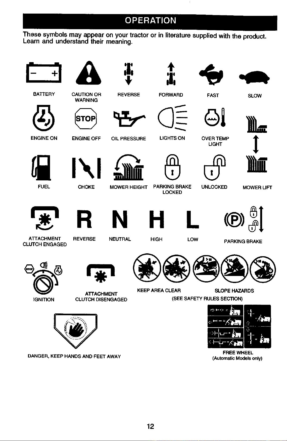
These symbols may appear on your tractor or in literature supplied with the product.
Learn and understand their meaning.
BATrERY CAUTION OR REVERSE FORWARD FAST SLOW
WARNING
ENG,NEONENGINEOFFO,LPRESSOREL.GRTSONOVI,_T_M.]
FUEL CHOKE MOWER HEIGHT PARKING BRAKE UNLOCKED MOWER LIFT
LOCKED
R N H L
A'I-rACHMENT REVERSE NEUTRAL HIGH LOW PARKING BRAKE
CLUTCH ENGAGED
_(_) ATTACHMENT KEEP AREA CLEAR SLOPE HAZARDS
IGNITION CLUTCH DISENGAGED (SEE SAFETY RULES SECTION)
DANGER, KEEP HANDS AND FEET AWAY
12
FREE WHEEL
(AutomaticModels only)
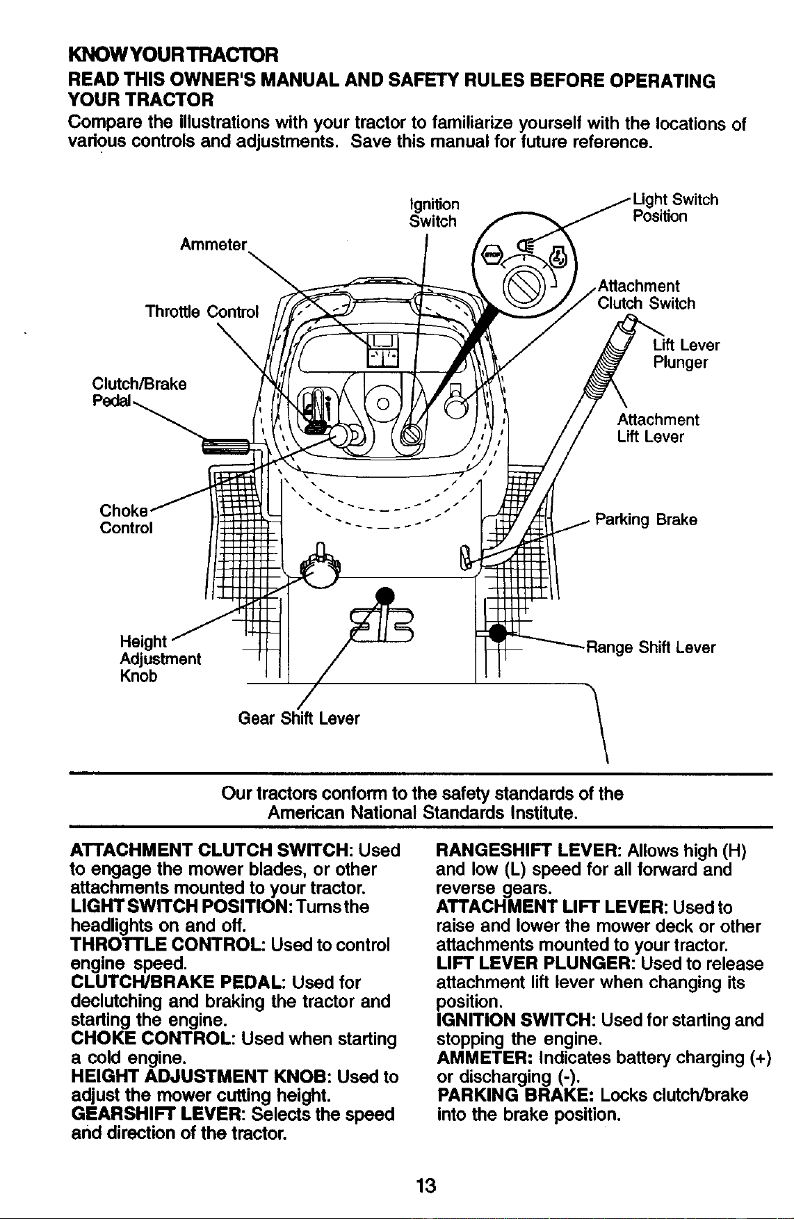
KNOWYOURTRACTOR
READ THIS OWNER'S MANUAL AND SAFETY RULES BEFORE OPERATING
YOUR TRACTOR
Compare the illustrationswith your tractorto familiarize yourselfwith the locationsof
various controlsand adjustments. Save this manual for future reference.
Ignition
Switch
Ammeter
Throttle Control
ControlCh°keAdjustmentKnobHeight ". 222222 --_"; _"_" "!
Gear Shift Lever
Light Switch
Position
hment
h Switch
Lift Lever
Plunger
Attachment
Lift Lever
Brake
Range Shift Lever
\
Our tractors conform to the safety standards of the
American National Standards Institute.
ATTACHMENT CLUTCH SWITCH: Used
to engage the mower blades, or other
attachments mounted to your tractor.
LIGHT SWITCH POSITION: Tums the
headlights on and off.
THROTTLE CONTROL: Used to control
engine speed.
CLUTCH/BRAKE PEDAL: Used for
declutching and braking the tractor and
starting the engine.
CHOKE CONTROL: Used when starting
a cold engine.
HEIGHT ADJUSTMENT KNOB: Used to
adjust the mower cutting height.
GEARSHIFT LEVER: Selects the speed
and direction of the tractor.
RANGESHIFT LEVER: Allows high (H)
and low (L) speed for all forward and
reverse gears.
ATTACHMENT LIFT LEVER: Used to
raise and lower the mower deck or other
attachments mounted to your tractor.
LIFT LEVER PLUNGER: Used to release
attachment lift lever when changing its
position.
IGNITION SWITCH: Used for starting and
stopping the engine.
AMMETER: Indicates battery charging (+)
or discharging (-).
PARKING BRAKE: Locks clutch/brake
into the brake position.
13
The operation of any tractor can result in foreign objects thrown into the
eyes, which can result in severe eye damage. Always wear safety
glasses or eye shields while operating your tractor or perform ng any
adjustments or repairs. We recommend standard safety glasses or a
wide vision safety mask worn over spectacles.
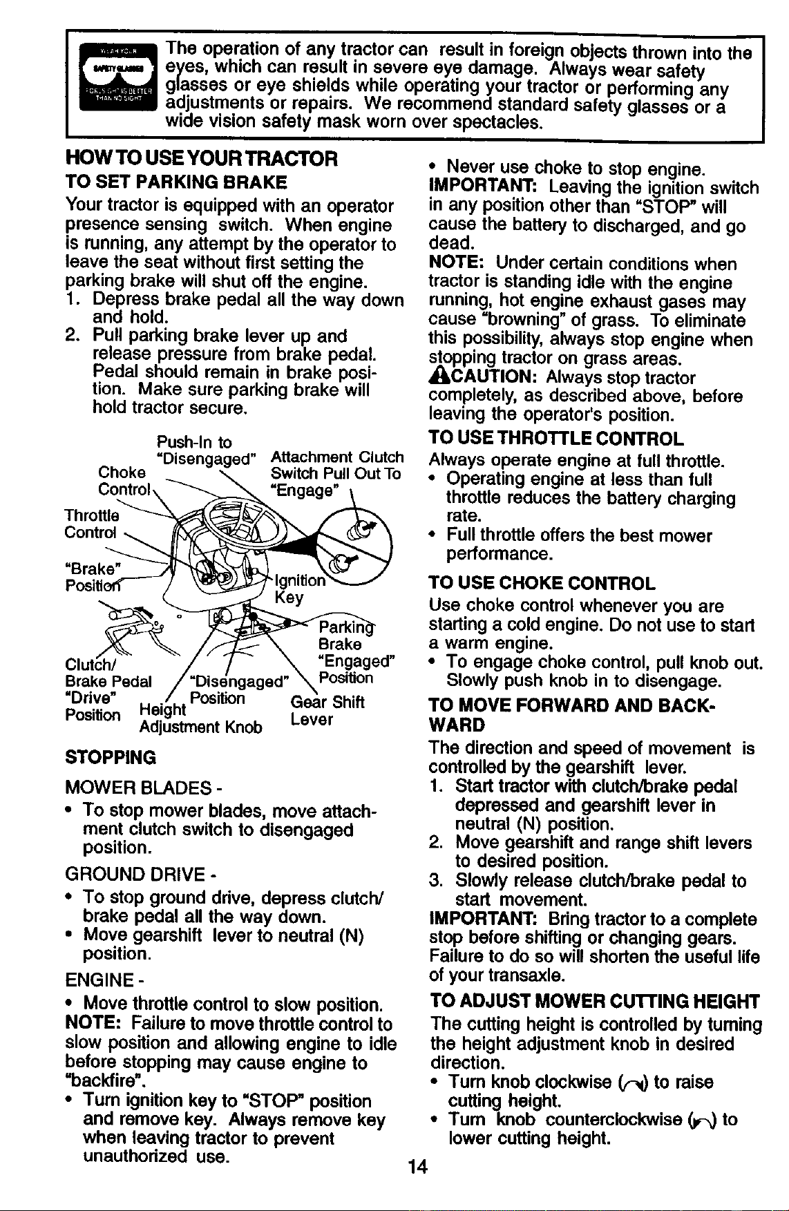
HOW TO USE YOUR TRACTOR
TO SET PARKING BRAKE
Your tractor is equipped with an operator
presence sensing switch. When engine
is running, any attempt by the operator to
leave the seat without first setting the
parking brake will shut oft the engine.
1. Depress brake pedal all the way down
and hold.
2. Pull parking brake lever up and
release pressure from brake pedal.
Pedal should remain in brake posi-
tion. Make sure parking brake will
hold tractor secure.
Push-In to
"Disengaged"
Choke
Control,
Attachment Clutch
Switch Pull Out To
"Engage"
Control
=Brake"
Key
Brake
ClutCh/ "Engaged"
Brake Pedal Position
"Ddve" Position Gear Shift
Position Adjustment Knob Lever
STOPPING
MOWER BLADES -
• To stop mower blades, move attach-
ment clutch switch to disengaged
position.
GROUND DRIVE -
• To stop ground ddve, depress clutch/
brake pedal all the way down.
• Move gearshift lever to neutral (N)
position.
ENGINE -
• Move throttle control to slow position.
NOTE: Failure to move throttle control to
slow position and allowing engine to idle
before stopping may cause engine to
"backfire".
•Tum ignition key to "STOP" position
and remove key. Always remove key
when leaving tractor to prevent
unauthorized use.
• Never use choke to stop engine.
IMPORTANT: Leaving the ignition switch
in any position other than =STOP" will
cause the battery to discharged, and go
dead.
NOTE: Under certain conditions when
tractor is standing idle with the engine
running, hot engine exhaust gases may
cause =browning" of grass. To eliminate
this possibility, always stop engine when
_LOcppingtractor on grass areas.
AUTION: Always stop tractor
completely, as described above, before
leaving the operator's position.
TO USE THROTTLE CONTROL
Always operate engine at full throttle.
• Operating engine at less than full
throttle reduces the battery charging
rate.
• Full throttle offers the best mower
performance.
TO USE CHOKE CONTROL
Use choke control whenever you are
starting a cold engine. Do not use to start
a warm engine.
• To engage choke control, pull knob out.
Slowly push knob in to disengage.
TO MOVE FORWARD AND BACK-
WARD
The direction and speed of movement is
controlled by the gearshift lever.
1. Start tractor with clutch/brake pedal
depressed and gearshift lever in
neutral (N) position.
2. Move gearshift and range shift levers
to desired position.
3. Slowly release clutch/brake pedal to
start movement.
IMPORTANT: Bring tractor to a complete
stop before shifting or changing gears.
Failure to do so will shorten the useful life
of your transaxle.
TO ADJUST MOWER CU'I-I'ING HEIGHT
The cutting height is controlled by tuming
the height adjustment knob in desired
direction.
• Turn knob clockwise _ to raise
cutting height.
•Tum knob counterclockwise (_ to
lower cutting height.
14
The cutting height range is approximately
1-1/2" to 4-1/2". The heights are mea-
sured from the ground to the blade tip
with the engine not running. These
heights are approximate and may vary
depending upon soil conditions, height of
grass and types of grass being mowed.
• The average lawn should be cut to
approximately 2-1/2 inches during the
cool season and to over 3 inches
during hot months. For healthier and
better looking lawns, mow often and
after moderate growth.
• For best cutting performance, grass
over 6 inches in height should be
mowed twice. Make the first cut
relatively high; the second to desired
height.
TO ADJUST GAUGE WHEELS
Gauge wheels are propedy adjusted
when they are slightly off the ground
when mower is at the desired cutting
height in operating position. Gauge
wheels then keep the deck in proper
position to help prevent scalping in most
terrain conditions.
NOTE: Adjust gauge wheels with tractor
on a flat level surface.
1. Adjust mower to desired cutting
height.
2. Lower mower with lift control. Re-
move rear retainer spring and clevis
pin which secure each gauge wheel.
3. Lower gauge wheels to ground.
Raise gauge wheels slightly to align
holes in bracket and gauge wheel bar
and insert clevis pins. Gauge wheels
should be slightly off the ground.
4. Replace retainer spdngs into clevis
pins.
Clevis Pin
Retainer
S
Gauge
Wheel
Wheel
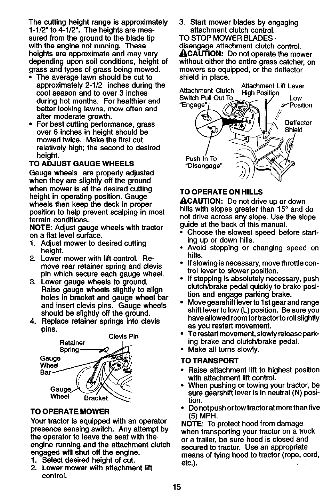
TO OPERATE MOWER
Your tractor is equipped with an operator
presence sensing switch. Any attempt by
the operator to leave the seat with the
engine running and the attachment clutch
engaged will shut off the engine.
1. Select desired height of cut.
2. Lower mower with attachment lift
control.
3. Start mower blades by engaging
attachment clutch control.
TO STOP MOWER BLADES -
disengage attachment clutch control.
ACAUTION: Do not operate the mower
without either the entire grass catcher, on
mowers so equipped, or the deflector
shield in place.
AttachmentLiftLever
"'0" ,ow
Enga_ [...'.!;"S._Position.
(._1_J _7..'..;'_ Deflector
Push In To _\\,_'%--_" _L_
"D,sengage" _--_--__
TO OPERATE ON HILLS
ACAUTION: Do not drive up or down
hills with slopes greater than 15 ° and do
not drive across any slope. Use the slope
guide at the back of this manual.
• Choose the slowest speed before start-
ing up or down hills.
• Avoid stopping or changing speed on
hills.
• If slowing is necessary, move throttle con-
trol lever to slower position.
• If stopping is absolutely necessary, push
clutch/brake pedal quickly to brake posi-
tion and engage parking brake.
• Move gearshift lever to 1stgear and range
shift lever to low (L) position. Be sure you
have allowed room for tractorto rollslightly
as you restart movement.
• To rastart movement, slowly release park-
ing brake and clutch/brake pedal.
• Make all turns slowly.
TO TRANSPORT
• Raise attachment lift to highest position
with attachment lift control.
• When pushing or towing your tractor, be
sure gearshift lever is in neutral (N) posi-
tion.
• Do not push or towtractor at more than five
(5) MPH.
NOTE: To protect hood from damage
when transporting your tractor on a truck
or a trailer, be sure hood is closed and
secured to tractor. Use an appropriate
means of tying hood to tractor (rope, cord,
etc.) ....
15
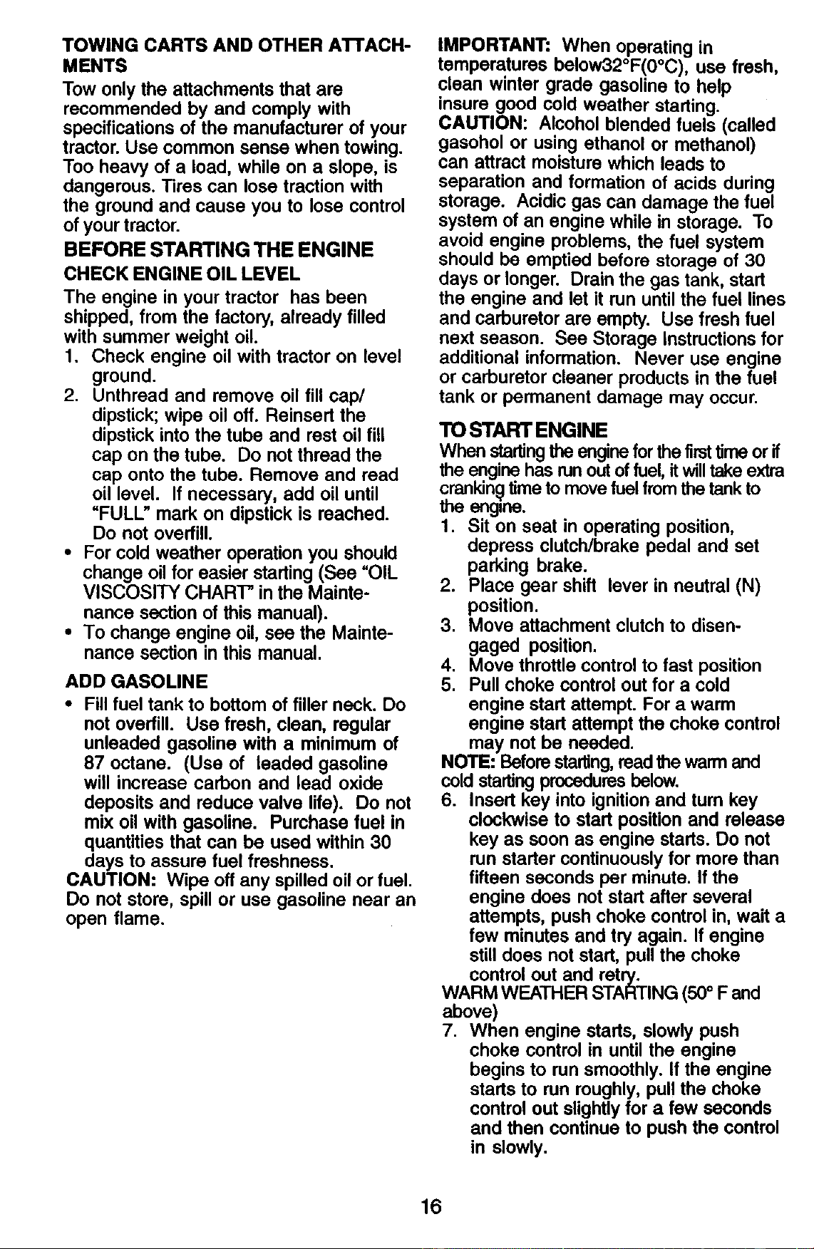
TOWING CARTS AND OTHER ATrACH-
MENTS
Tow only the attachments that are
recommended by and comply with
specifications of the manufacturer of your
tractor. Use common sense when towing.
Too heavy of a load, while on a slope, is
dangerous. Tires can lose traction with
the ground and cause you to lose control
of your tractor.
BEFORE STARTING THE ENGINE
CHECK ENGINE OIL LEVEL
The engine in your tractor has been
shipped, from the factory, already filled
with summer weight oil.
1. Check engine oil with tractor on level
ground.
2. Unthread and remove oil fill cap/
dipstick; wipe oil off. Reinsert the
dipstick into the tube and rest oil fill
cap on the tube. Do not thread the
cap onto the tube. Remove and read
oil level. If necessary, add oil until
"FULL" mark on dipstick is reached.
Do not overfill.
• For cold weather operation you should
change oil for easier starting (See "OIL
VISCOSITY CHART' in the Mainte-
nance section of this manual).
• To change engine oil, see the Mainte-
nance section in this manual.
ADD GASOLINE
• Fill fuel tank to bottom of filler neck. Do
not overfill. Use fresh, clean, regular
unleaded gasoline with a minimum of
87 octane. (Use of leaded gasoline
will increase carbon and lead oxide
deposits and reduce valve life). Do not
mix oil with gasoline. Purchase fuel in
quantities that can be used within 30
days to assure fuel freshness.
CAUTION: Wipe off any spilled oil or fuel.
Do not store, spill or use gasoline near an
open flame.
IMPORTANT: When operating in
temperatures below32°F(0oc), use fresh,
clean winter grade gasoline to help
insure good cold weather starting.
CAUTION: Alcohol blended fuels (called
gasohol or using ethanol or methanol)
can attract moisture which leads to
separation and formation of acids during
storage. Acidic gas can damage the fuel
system of an engine while in storage. To
avoid engine problems, the fuel system
should be emptied before storage of 30
days or longer. Drain the gas tank, start
the engine and let it run until the fuel lines
and carburetor are empty. Use fresh fuel
next season. See Storage instructions for
additional information. Never use engine
or carburetor cleaner products in the fuel
tank or permanent damage may occur.
TO STARTENGINE
When startingthe engine for the firsttime or if
the engine has run outof fuel, it willtake extra
crankin_ time to move fuel from the tank to
the engine.
1. Sit on seat in operating position,
depress clutch/brake pedal and set
parking brake.
2. Place gear shift lever in neutral (N)
position.
3. Move attachment clutch to disen-
gaged position.
4. Move throttle control to fast position
5. Pull choke control out for a cold
engine start attempt. For a warm
engine start attempt the choke control
may not be needed.
NOTE: Before starting,read the warm and
cold starting procedures below.
6. Insert key into ignition and rum key
clockwise to start position and release
key as soon as engine starts. Do not
run starter continuously for more than
fifteen seconds per minute. If the
engine does not start after several
attempts, push choke control in, wait a
few minutes and try again. If engine
still does not start, pull the choke
control out and retry.
WARM WEATHER STARTING (50° F and
above)
7. When engine starts, slowly push
choke control in until the engine
begins to run smoothly, if the engine
starts to run roughly, pull the choke
control out slightly for a few seconds
and then continue to push the control
in slowly.
16
• The attachments and ground drive can
now be used. If the engine does not
accept the load, restart the engine and
allow it to warm up for one minute
using the choke as described above.
COLD WEATHER STARTING (50 ° F and
below)
7. When engine starts, slowly push
choke control in until the engine
begins to run smoothly. Continue to
push the choke control in small steps
allowing the engine to accept small
changes in speed and load, until the
choke control is fully in. If the engine
starts to run roughly, pull the choke
control out slightly for a few seconds
and then continue to push the control
in slowly. This may require an engine
warm-up period from several seconds
to several minutes, depending on the
temperature.
• The attachments can be used during
the engine warm-up period and may
require the choke control be pulled out
slightly.
NOTE: If at a high altitude (above 3000
feet) or in cold temperatures (below 32 F)
the carburetor fuel mixture may need to
be adjusted for best engine performance.
See =-IO ADJUST CARBURETOR" in the
Service and Adjustments section of this
manual.
MOWING TIPS
• Tire chains cannot be used when the
mower housing is attached to tractor.
• Mower should be properly leveled for
best mowing performance. See ='1"O
LEVEL MOWER HOUSING" in the
Service and Adjustments section of this
manual.
• The left hand side of mower should be
used for trimming.
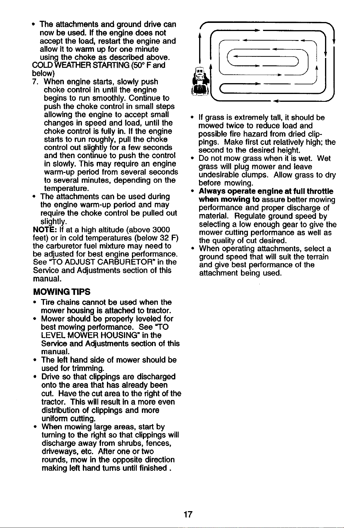
• Drive so that clippings are discharged
onto the area that has already been
cut. Have the cut area to the right of the
tractor. This will result in a more even
distribution of clippings and more
uniform cutting.
• When mowing large areas, start by
turning to the right so that clippings will
discharge away from shrubs, fences,
driveways, etc. After one or two
rounds, mow in the opposite direction
making left hand turns until finished.
• If grass is extremely tall, it should be
mowed twice to reduce load and
possible fire hazard from dried clip-
pings. Make first cut relatively high; the
second to the desired height.
• Do not mow grass when it is wet. Wet
grass will plug mower and leave
undesirable clumps. Allow grass to dry
before mowing.
• Always operate engine at full throttle
when mowing to assure better mowing
performance and proper discharge of
material. Regulate ground speed by
selecting a low enough gear to give the
mower cutting performance as well as
the quality of cut desired.
• When operating attachments, select a
ground speed that will suit the terrain
and give best performance of the
attachment being used.
17
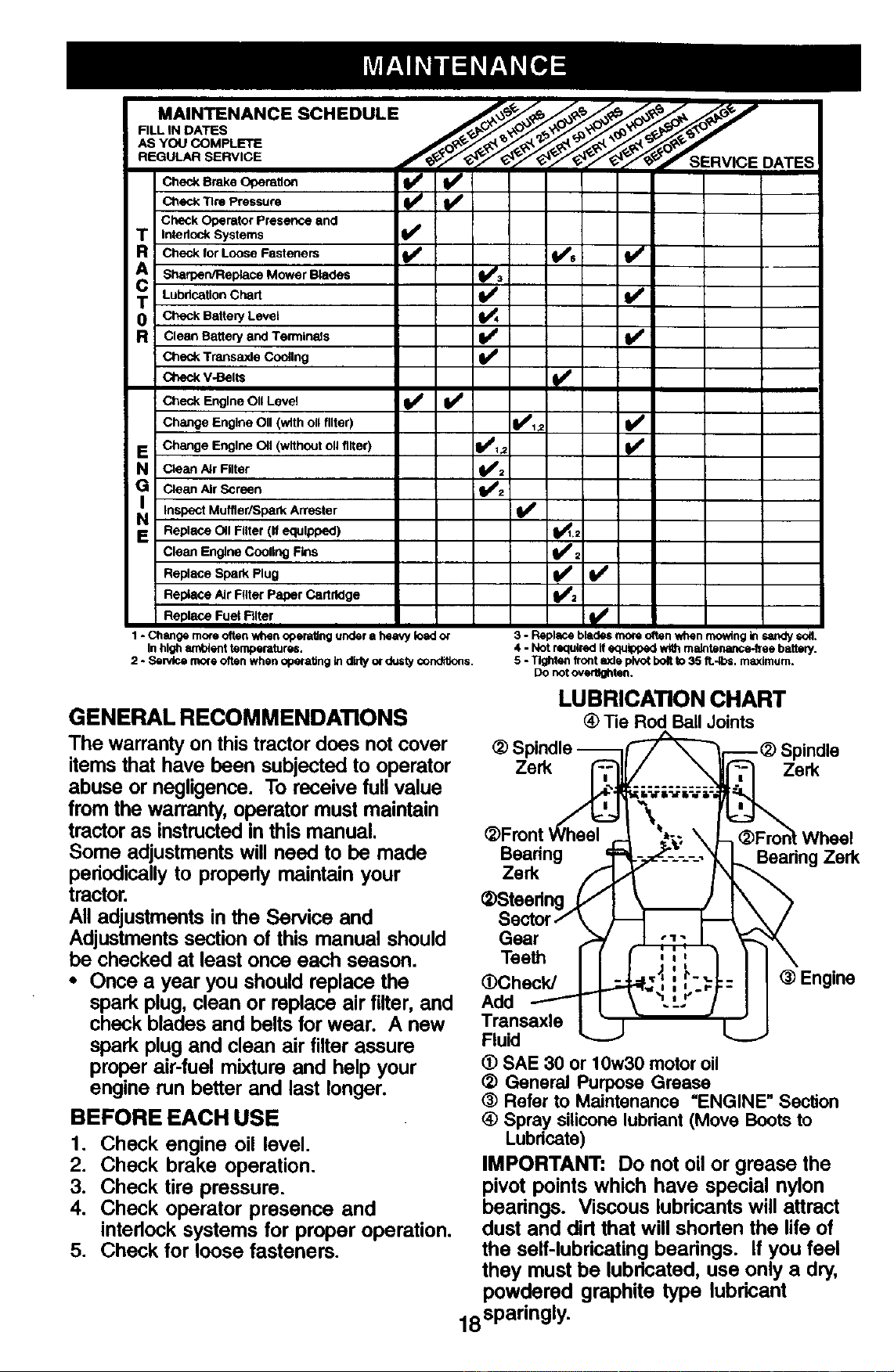
MAINTENANCE SCHEDULE _._. _._/'_ _, f
Check Brake C_oeraitoft
v"
Tire Pressure
Check Operator Presence and
T InterlockSystems
R Check for Loose Fasteners
A Sharpen/Replace Mower Blades
T LubricationChart
0 Check Battery Level
R Clean Battery and Termlnads
Check; Transaxle Cooitng
Check V-Belts
Check Engine OII Level
Change Engine OII (with ollfilter)
E Change Engine 011(withoutoll filter)
N Claan/=JrFilter
G Clean Air Screen
IN Inspect Muffler/Spark
Arrester
E ReplaCe OII Filter (If equipped)
Clean Engine COOlingFins
Replace Spark Plug
Replace Air Filter Paper Cartridge
I Replace Fuel Rlter
v'
'/ !v'
v0 v'
V' _.,
v'
1 - Change more often when operating under a heavy Ioed or
In high ambient temperatures.
2 - Sen,tce mo_eoften when opefaitng In dfrty or dusty condit_cns.
3 - Replace blades more otten when mowing In sandy so_.
4 - Not required it equipped _ maintemmce-free battJry.
5 - Tighten front axle pl'_t bolt to 35 R.-Ibs. maximum.
Do notoverHghten.
GENERAL RECOMMENDATIONS
The warranty on this tractor does not cover
items that have been subjected to operator
abuse or negligence. To receive full value
from the warranty, operator must maintain
tractor as instructed in this manual.
Some adjustments will need to be made
periodically to properly maintain your
tractor.
All adjustments in the Service and
Adjustments section of this manual should
be checked at least once each season.
• Once a year you should replace the
spark plug, clean or replace air filter, and
check blades and belts for wear. A new
spark plug and clean air tilter assure
proper air-fuel mixture and help your
engine run better and last longer.
BEFORE EACH USE
1. Check engine oil level.
2. Check brake operation.
3. Check tire pressure.
4. Check operator presence and
interlock systems for proper operation.
5. Check for loose fasteners.
LUBRICATION CHART
_) Tie Rod Ball Joints
_) Spindle -_) Spindle
Zerk Zerk
Bearing
Zerk
(_Steedng _(
Sector f
Gear
Teeth
(_Checld
Add
Transaxle
Fluid
Wheel
_,Baadng Zerk
I'
® Engine
(_ SAE 30 or 10w30 motor oil
(_ General Purpose Grease
(_ Refer to Maintenance "ENGINE" Section
(_ Spray silicone lubriant(Move Bootsto
Lubdcate)
IMPORTANT: Do not oil or grease the
pivot points which have special nylon
bearings. Viscous lubricants will attract
dust and dirt that will shorten the life of
the self-lubricating bearings. If you feel
they must be lubricated, use only a dry,
powdered graphite type lubricant
18sparingly.
TRACTOR
Always observe safety rules when
performing any maintenance.
BRAKE OPERATION
If tractor requires more than six (6) feet
stopping distance at high speed in
highest gear, then brake must be ad-
justed. (See "TO ADJUST BRAKE" in the
Service and Adjustments section of this
manual).
TIRES
• Maintain proper air pressure in all tires
(See =PRODUCT SPECIFICATIONS"
section of this manual).
• Keep tires free of gasoline, oil, or insect
control chemicals which can harm
rubber.
• Avoid stumps, stones, deep ruts, sharp
objects and other hazards that may
cause tire damage.
NOTE: To seal tire punctures and prevent
flat tires due to slow leaks, tire sealant
may be purchased from your local parts
dealer. Tire sealant also prevents tire dry
rot and corrosion.
OPERATOR PRESENCE SYSTEM
Be sure operator presence and interlock
systems are working propedy. If your
tractor does not function as described,
repair the problem immediately.
• The engine should not start unless the
brake pedal is fully depressed and
attachement clutch control is in the
disengaged position.
• When the engine is running, any
attempt by the operator to leave the
seat without first setting the parking
brake should shut off the engine.
• When the engine is running and the
attachment clutch is engaged, any
attempt by the operator to leave the
seat should shut off the engine.
• The attachment clutch should never
operate unless the operator is in the
seat.
BLADE CARE
For best results mower blades must be
kept sharp. Replace bent or damaged
blades.
BLADE REMOVAL
1. Raise mower to highest position to
allow access to blades.
2. Remove hex bolt, lock washer and flat
washer securing blade.
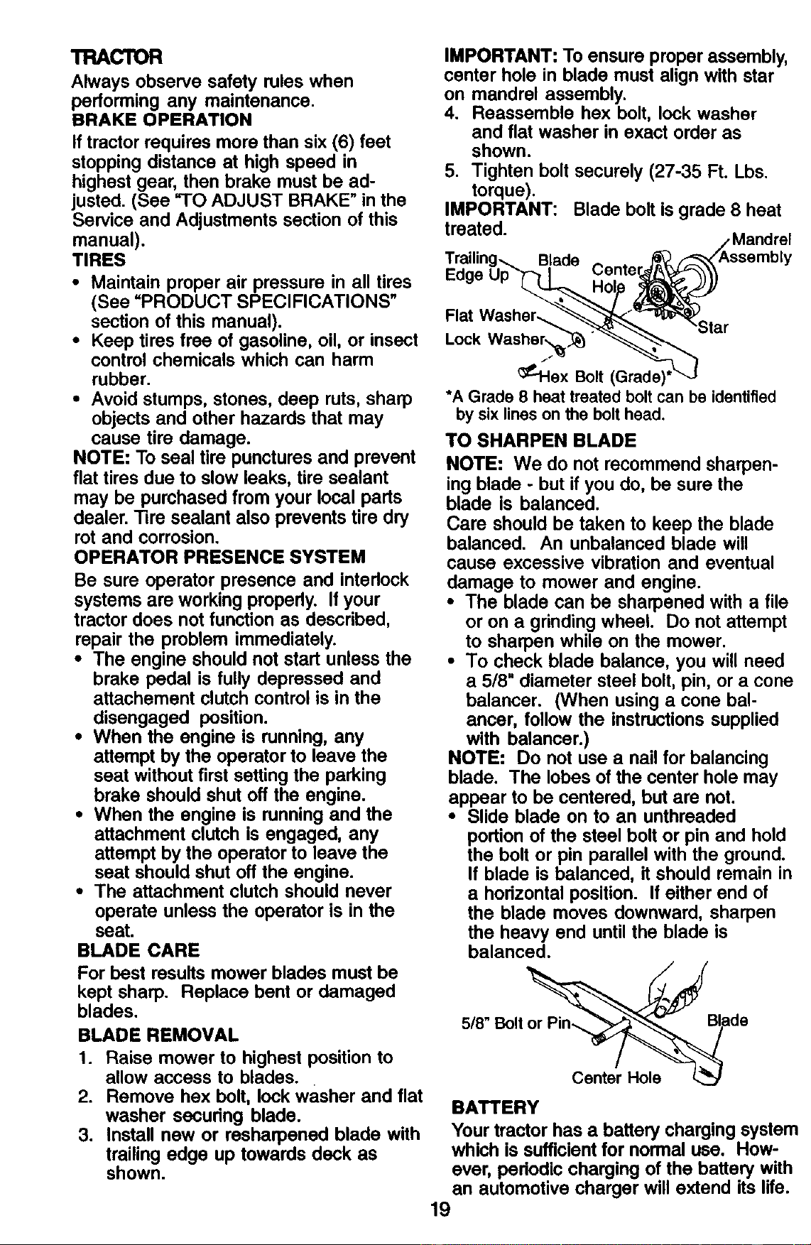
3. Install new or resharpened blade with
trailing edge up towards deck as
shown.
IMPORTANT: To ensure proper assembly,
center hole in blade must align with star
on mandrel assembly.
4. Reassemble hex bolt, lock washer
and flat washer in exact order as
shown.
5. Tighten bolt securely (27-35 Ft. Lbs.
torque).
IMPORTANT: Blade bolt is grade 8 heat
treated.
Blade
Cente
Flat
Lock
_--lex Bolt (Grade)'
*A Grade 8 heat treated bolt can be identified
by six lines on the bolt head.
TO SHARPEN BLADE
NOTE: We do not recommend sharpen-
ing blade - but if you do, be sure the
blade is balanced.
Care should be taken to keep the blade
balanced. An unbalanced blade will
cause excessive vibration and eventual
damage to mower and engine.
• The blade can be sharpened with a file
or on a grinding wheel. Do not attempt
to sharpen while on the mower.
• To check blade balance, you will need
a 5/8" diameter steel bolt, pin, or a cone
balancer. (When using a cone bal-
ancer, follow the instructions supplied
with balancer.)
NOTE: Do not use a nail for balancing
blade. The lobes of the center hole may
appear to be centered, but are not.
• Slide blade on to an unthreaded
portion of the steel bolt or pin and hold
the bolt or pin parallel with the ground.
If blade is balanced, it should remain in
a horizontal position. If either end of
the blade moves downward, sharpen
the heavy end until the blade is
balanced.
5/8" Bolt de
Center Hole
BATTERY
Your tractor has a battery charging system
which is sufficient for normal use. How-
ever, pedodic charging of the battery with
an automotive charger will extend its life.
19
• Keep battery and terminals clean.
• Keep battery belts tight.
• Keep small vent holes open.
• Recharge at 6-10 amperes for I hour.
NOTE: The original equipment battery on
your tractor is maintenance free. Do not
attempt to open or remove caps or covers.
Adding or checking level of electrolyte is
not necessary.
TO CLEAN BATTERYAND TERMINALS
Corrosion and dirt on the battery and
terminals can cause the battery to =leak"
power,
1. Remove terminal guard.
2, Disconnect BLACK battery cable first
then RED battery cable and remove
battery from tractor.
3. Rinse the battery with plain water and
dry.
4, Clean terminals and battery cable ends
with wire brush until bright.
5. Coat terminals with grease or petro-
leum jelly.
6. Reinstall battery (See =REPLACING
BATTERY" in the SERVICE AND
ADJUSTMENTS section of this
manual).
TRANSAXLE COOLING
Keep transaxle free from build-up of dirt
and chaff which can restrict cooling.
CHECK TRANSAXLE OIL LEVEL
1. Block up rear axle securely.
2. Remove left rear wheel by removing
hub bolts.
3. Remove filler plug from transaxle. Oil
level must be even with plug threads. If
necessary, fill with SAE 30 motor oil,
API SF-SJ. Replace filler plug.
4. Reassemble wheel to hub.
o
o
Rug
Filler
V-BELTS
Check V-beltsfor deteriorationand wear
after 100 hoursof operationand replace if
necessary.The beltsare not adjustable.
Replace beltsif they beginto slipfrom
wear.
ENGINE
LUBRICATION
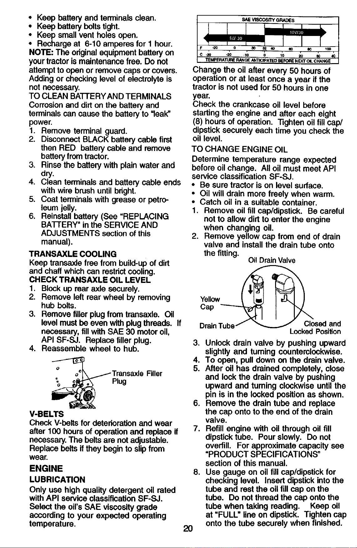
Only use high quality detergent oil rated
with API service classification SF-SJ.
Select the oil's SAE viscosity grade
according to your expected operating
temperature,
•_0 -20 -10 O 10 20 30
TEMPERATURERANGEANTICIPATEDBEFOR_NEXTOILCHANGE
Change the oil after every 50 hours of
operation or at least once a year if the
tractor is not used for 50 hours in one
year.
Check the crankcase oil level before
starting the engine and after each eight
(8) hours of operation. "lighten oil fill cap/
dipstick securely each time you check the
oil level.
TO CHANGE ENGINE OIL
Determine temperature range expected
before oil change. All oil must meet API
service classification SF-SJ.
• Be sure tractor is on level surface.
• Oil will drain more freely when warm.
• Catch oil in a suitable container.
1. Remove oil fill cap/dipstick. Be careful
not to allow dirt to enter the engine
when changing oil.
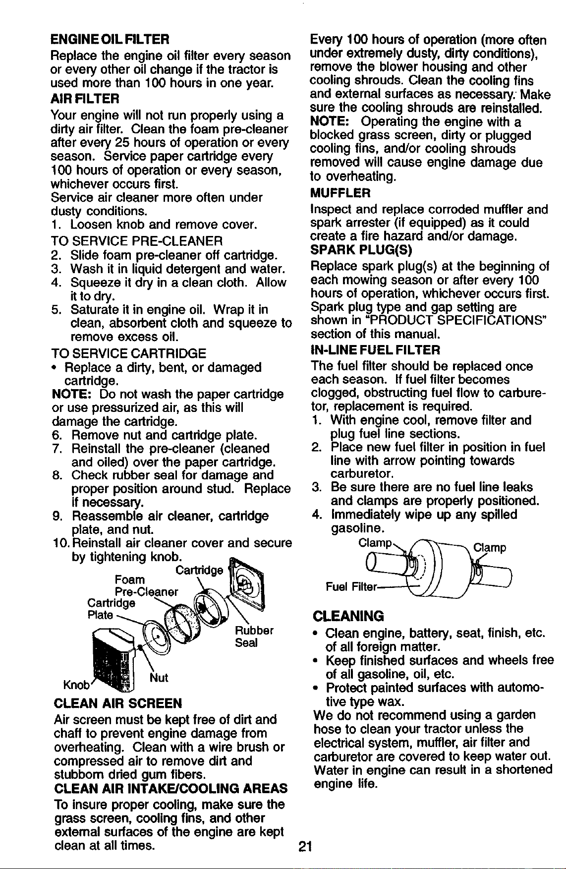
2. Remove yellow cap from end of drain
valve and install the drain tube onto
the fitting.
Oil Drain Valve
Cap
DrainTubej
_osed and
Locked Position
2O
3. Unlock drain valve by pushing upward
slightly and tuming counterclockwise.
4. To open, pull down on the drain valve.
5. After oil has drained completely, close
and lock the drain valve by pushing
upward and turning clockwise until the
pin is in the locked position as shown.
6. Remove the drain tube and replace
the cap onto to the end of the drain
valve.
7. Refill engine with oil through oil fill
dipstick tube. Pour slowly. Do not
overfill. For approximate capacity see
"PRODUCT SPECIFICATIONS"
section of this manual.
8. Use gauge on oil fill cap/dipstick for
checking level. Insert dipstick into the
tube and rest the oil fill cap on the
tube. Do not thread the cap onto the
tube when taking reading. Keep oil
at =FULL" line on dipstick. Tighten cap
onto the tube securely when finished.
ENGINE OIL FILTER
Replace the engine oil filter every season
or every other oil change if the tractor is
used more than 100 hours in one year.
AIR FILTER
Your engine will not run properly using a
dirty air filter. Clean the foam pre-cleaner
after every 25 hours of operation or every
season. Service paper cartddge every
100 hours of operation or every season,
whichever occurs first.
Service air cleaner more often under
dusty conditions.
1. Loosen knob and remove cover.
TO SERVICE PRE-CLEANER
2. Slide foam pre-cleaner off cartridge.
3. Wash it in liquid detergent and water.
4. Squeeze it dry in a clean cloth. Allow
it to dry.
5. Saturate it in engine oil. Wrap it in
clean, absorbent cloth and squeeze to
remove excess oil.
TO SERVICE CARTRIDGE
• Replace a dirty, bent, or damaged
cartridge.
NOTE: Do not wash the paper cartridge
or use pressurized air, as this will
damage the cartridge.
6. Remove nut and cartridge plate.
7. Reinstall the pre-cleaner (cleaned
and oiled) over the paper cartridge.
8. Check rubber seal for damage and
proper position around stud. Replace
if necessary.
9. Reassemble air cleaner, cartridge
plate, and nut.
10. Reinstall air cleaner cover and secure
by tightening knob.
Foam
Pre-Cleaner
Cartridge
Rubber
Se_
Nut
Knob
CLEAN AIR SCREEN
Air screen must be kept free of dirt and
chaff to prevent engine damage from
overheating. Clean with a wire brush or
compressed air to remove dirt and
stubbom dded gum fibers.
CLEAN AIR INTAKE/COOLING AREAS
To insure proper cooling, make sure the
grass screen, cooling fins, and other
extemal surfaces of the engine are kept
clean at all times.
Every 100 hours of operation (more often
under extremely dusty, dirty conditions),
remove the blower housing and other
cooling shrouds. Clean the cooling fins
and external surfaces as necessary. Make
sure the cooling shrouds are reinstalled.
NOTE: Operating the engine with a
blocked grass screen, dirty or plugged
cooling fins, and/or cooling shrouds
removed will cause engine damage due
to overheating.
MUFFLER
Inspect and replace corroded muffler and
spark arrester (if equipped) as it could
create a fire hazard and/or damage.
SPARK PLUG(S)
Replace spark plug(s) at the beginning of
each mowing season or after every 100
hours of operation, whichever occurs first.
Spark plug type and gap setting are
shown in "PRODUCT SPECIFICATIONS"
section of this manual.
IN-LINE FUEL FILTER
The fuel filter should be replaced once
each season. If fuel filter becomes
clogged, obstructing fuel flow to carbure-
tor, replacement is required.
1. With engine cool, remove filter and
plug fuel line sections.
2. Place new fuel filter in position in fuel
line with arrow pointing towards
carburetor.
3. Be sure there are no fuel line leaks
and clamps are propedy positioned.
4. Immediately wipe up any spilled
gasoline.
Fuel Filter__ "_-_J
CLEANING
• Clean engine, battery, seat, finish, etc.
of all foreign matter.
• Keep finished surfaces and wheels free
of all gasoline, oil, etc.
• Protect painted surfaces with automo-
tive type wax.
We do not recommend using a garden
hose to clean your tractor unless the
electrical system, muffler, air filter and
carburetor are covered to keep water out.
Water in engine can result in a shortened
engine life.
21
WARNING: TO AVIOD SERIOUS INJURY, BEFORE PERFORMING ANY
SERVICE OR ADJUSTMENTS:
1. Depress clutch/brake pedal fully and set parking brake.
2. Place gearshift lever in neutral (N) position.
3. Place attachment clutch in =DISENGAGED" position.
4. Turn ignition key "OFF" and remove key.
5. Make sure the blades and all moving parts have completely stopped.
6. Disconnect spark plug wire from spark plug and place wire where it cannot
come in contact with plug.
TRACTOR
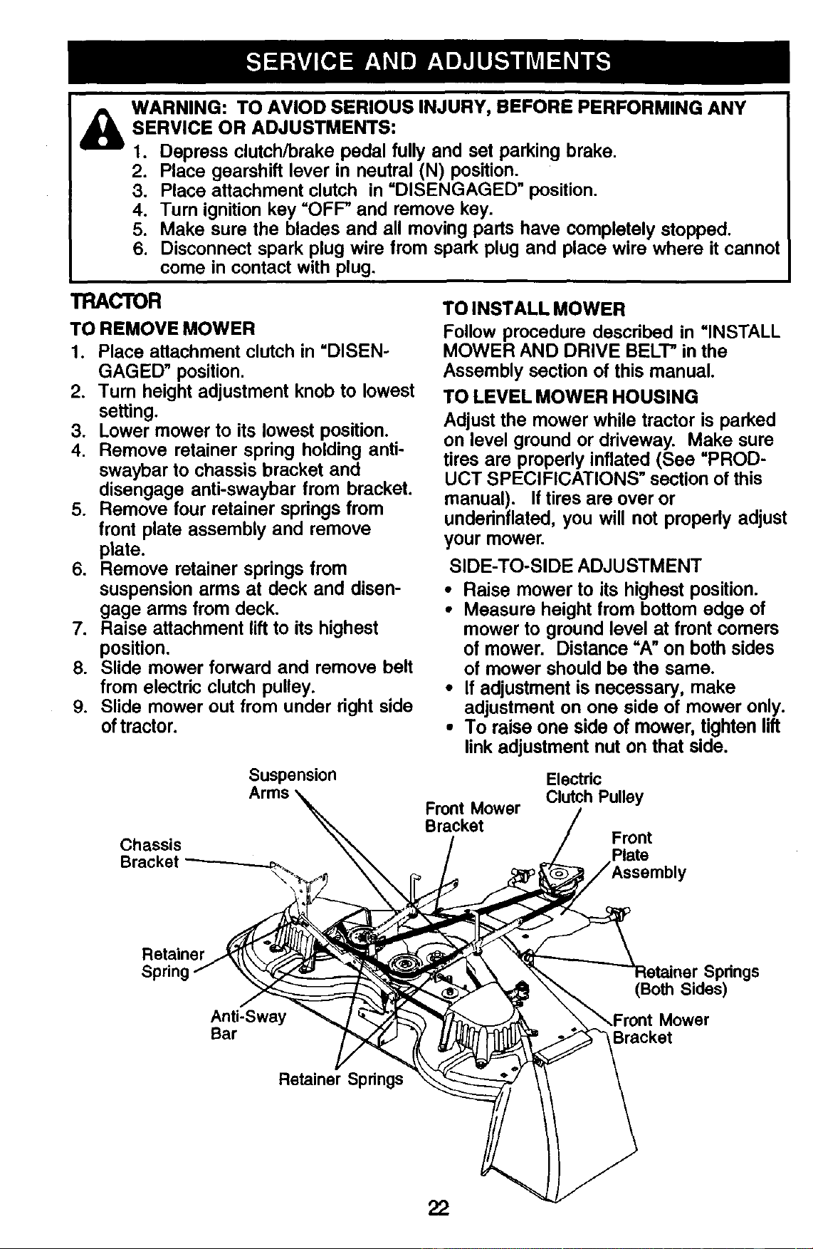
TO REMOVE MOWER
1. Place attachment clutch in "DISEN-
GAGED" position.
2. Turn height adjustment knob to lowest
setting.
3. Lower mower to its lowest position.
4. Remove retainer spring holding anti-
swaybar to chassis bracket and
disengage anti-swaybar from bracket.
5. Remove four retainer springs from
front plate assembly and remove
plate.
6. Remove retainer springs from
suspension arms at deck and disen-
gage arms from deck.
7. Raise attachment lift to its highest
position.
8. Slide mower forward and remove belt
from electric clutch pulley.
9. Slide mower out from under right side
of tractor.
Suspension
Chassis
Bracket
TO INSTALL MOWER
Follow procedure descdbed in =INSTALL
MOWER AND DRIVE BELT" in the
Assembly section of this manual.
TO LEVEL MOWER HOUSING
Adjust the mower while tractor is parked
on level ground or driveway. Make sure
tires are propedy inflated (See =PROD-
UCT SPECIFICATIONS" section of this
manual). If tires are over or
underinflated, you will not properly adjust
your mower.
SIDE-TO-SIDE ADJUSTMENT
• Raise mower to its highest position.
• Measure height from bottom edge of
mower to ground level at front comers
of mower. Distance =A" on both sides
of mower should be the same.
• If adjustment is necessary, make
adjustment on one side of mower only.
• To raise one side of mower, tighten lift
link adjustment nut on that side.
Front Mower
Bracket
Electric
Clutch Pulley
Front
Plate
Retainer
Anti-Sway
Bar
Springs
(Both Sides)
Mower
Bracket
Retainer Springs
22
• To lower one side of mower, loosen lift
link adjustment nut on that side.
NOTE: Each full turn of adjustment nut
will change mower height about 3/16".
• Recheck measurements after adjust-
ing.
BottomEdge of BottomEdgeof
Mower to Ground Mower to Ground
(_ Suspension
I I ,_'--_ _ Lift Link
_Adjustment
_Nut
Mandrel
BOTH FRONT UNKS MUST BE EQUAL
IN LENGTH
Nut
-Nut "G"
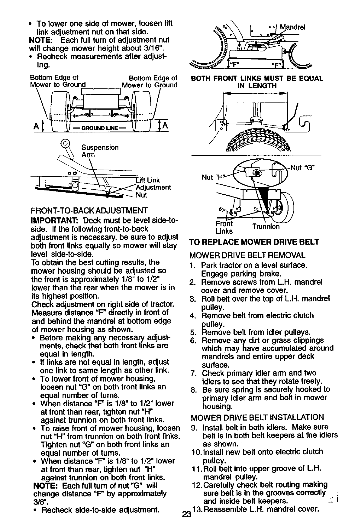
FRONT-TO-BACK ADJUSTMENT
IMPORTANT: Deck must be level side-to-
side. If the following front-to-back
adjustment is necessary, be sure to adjust
both front links equally so mower will stay
level side-to-side.
To obtain the best cutting results, the
mower housing should be adjusted so
the front is approximately 1/8" to 1/2"
lower than the rear when the mower is in
its highest position.
Check adjustment on right side of tractor.
Measure distance =P directly in front of
and behind the mandrel at bottom edge
of mower housing as shown.
• Before making any necessary adjust-
ments, check that both front links are
equal in length.
• If links are not equal in length, adjust
one link to same length as other link.
• To lower front of mower housing,
loosen nut "G" on both front links an
equal number of turns.
• When distance "P is 1/8" to 1/2" lower
at front than rear, tighten nut =H"
against trunnion on both front links.
• To raise front of mower housing, loosen
nut "H" from trunnion on both front links.
Tighten nut "G" on both front links an
equal number of tums.
• When distance "P is 1/8" to 1/2" lower
at front than rear, tighten nut "H"
against trunnion on both front links.
NOTE: Each full tum of nut "G" will
change distance =P by approximately
3/8".
• Recheck side-to-side adjustment.
Trunnion
Links
TO REPLACE MOWER DRIVE BELT
MOWER DRIVE BELT REMOVAL
1. Park tractor on a level surface.
Engage parking brake.
2. Remove screws from L.H. mandrel
cover and remove cover.
3. Roll belt over the top of L.H. mandrel
pulley.
4. Remove belt from electdc clutch
pulley.
5. Remove belt from idler pulleys.
6. Remove any dirt or grass clippings
which may have accumulated around
mandrels and entire upper deck
surface.
7. Check primary idler arm and two
idlers to see that they rotate freely.
8. Be sure spring is securely hooked to
primary idler arm and bolt in mower
housing.
MOWER DRIVE BELT INSTALLATION
9. Install belt in both idlers. Make sure
belt is in both belt keepers at the idlers
as shown.'
10. Install new belt onto electric clutch
pulley.
11 .Roll belt into upper groove of LH.
mandrel pulley.
12.Carefully check belt routing making
sure belt is in the grooves correctly :
and inside belt keepers.
2313. Reassemble LH. mandrel cover.

L.H.
Mandrel
Cover
Idler
Pulleys
Pdmary Idler Arm
Spring
Electric
Clutch
Pulley
L.H.
Mandrel
Bolt in
Mower
Housing
Mower Drive Belt
Belt Keepers
TO REPLACE MOWER BLADE DRIVE
BELT
Park the tractor on level surface. Engage
parking brake.
1. Remove mower drive belt (See =TO
REPLACE MOWER DRIVE BELT" in
this section of this manual).
2. Remove mower (See "TO REMOVE
MOWER" in this section of this
manual).
3. Remove screws from R.H. mandrel
cover and remove cover. Unhook
spring from bolt on mower housing.
4. Carefully roll belt off R.H. mandrel
pulley.
5. Remove belt from center mandrel
pulley, idler pulley, and L.H. mandrel
pulley.
6. Remove any dirt or grass which may
have accumulated around mandrels
and entire upper deck surface.
7. Check secondary idler arm and idler
to see that they rotate freely.
8. Be sure spring is hooked in secondary
idler arm and sway-bar bracket.
9. Install new belt in lower groove of L.H.
mandrel pulley, idler pulley, and
center mandrel pulley as shown.
10. Roll belt over R.H. mandrel pulley.
Make sure belt is in all grooves
properly.
11. Reconnect spdng to bolt in mower
housing and reinstall R.H. mandrel
cover.
12. Reinstall mower to tractor (See
=INSTALL MOWER AND DRIVE
BELT" in the Assembly section of this
manual).
13. Reassemble mower drive belt (See
"TO REPLACE MOWER DRIVE BELT"
in this section of this manual).
Mower Blade
L.H. Ddve Belt Center
Mandrel
R.H. Mandrel
Cover
Screw
Idler Arm
Bracket
Pulley
TO ADJUST ATTACHMENT CLUTCH
The electdc clutch should provide years
of service. The clutch has a built-in brake
that stops the pulley within 5 seconds.
Eventually, the intemal brake will wear
which may cause the mower blades to
not engage, or, to not stop as required.
Adjustments should be made by a Sears
or other qualified service center.
1. Make sure attachment clutch and
ignition switches are in =OFP position.
24
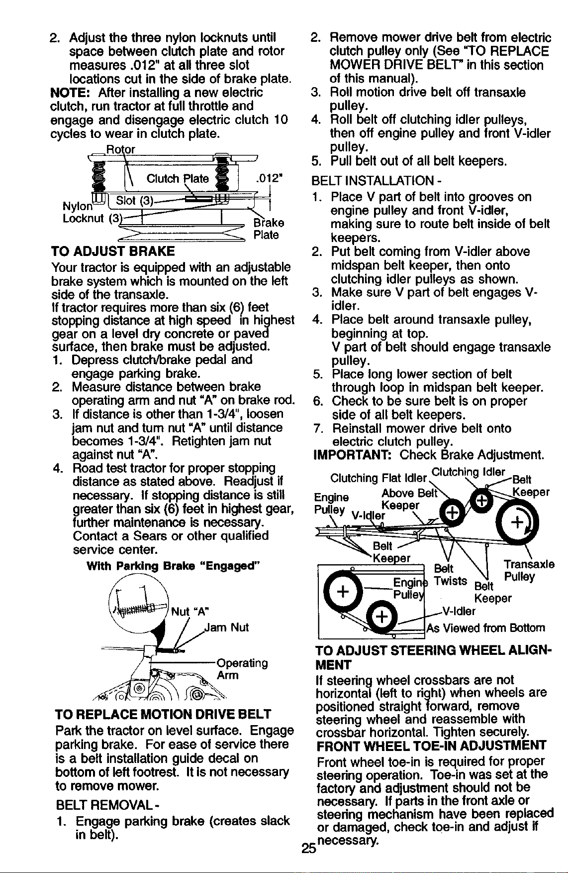
2. Adjust the three nylon Iocknuts until
space between clutch plate and rotor
measures .012" at all three slot
locations cut in the side of brake plate.
NOTE: After installing a new electric
clutch, run tractor at full throttle and
engage and disengage electric clutch 10
cycles to wear in clutch plate.
_Rotor _._
l c,utch .,o 01
N Ion_=v/ Slot (3) =_ J I
LlY_knut(3)---_"-'-- I
i_ _. Plate
TO ADJUST BRAKE
Your tractor is equipped with an adjustable
brake system which is mounted on the left
side of the transaxle.
If tractor requires more than six (6) feet
stopping distance at high speed in highest
gear on a level dry concrete or paved
surface, then brake must be adjusted.
1. Depress clutch/brake pedal and
engage parking brake.
2. Measure distance between brake
operating arm and nut "A" on brake rod.
3. If distance is other than 1-3/4", loosen
jam nut and tum nut =A" until distance
becomes 1-3/4". Retighten jam nut
against nut "A".
4. Road test tractor for proper stopping
distance as stated above. Readjust if
necessary. If stopping distance is still
greater than six (6) feet in highest gear,
further maintenance is necessary.
Contact a Sears or other qualified
service center.
With Parking Brake "Engaged"
=A"
Nut
Operating
Arm
TO REPLACE MOTION DRIVE BELT
Park the tractor on level surface. Engage
parking brake. For ease of service there
is a belt installation guide decal on
bottom of left footrest. It is not necessary
to remove mower.
BELT REMOVAL -
1. Engage parking brake (creates slack
in belt).
2. Remove mower drive belt from electric
clutch pulley only (See "TO REPLACE
MOWER DRIVE BELT" in this section
of this manual).
3. Roll motion ddve belt off transaxle
pulley.
4. Roll belt off clutching idler pulleys,
then off engine pulley and front V-idler
pulley.
5. Pull belt out of all belt keepers.
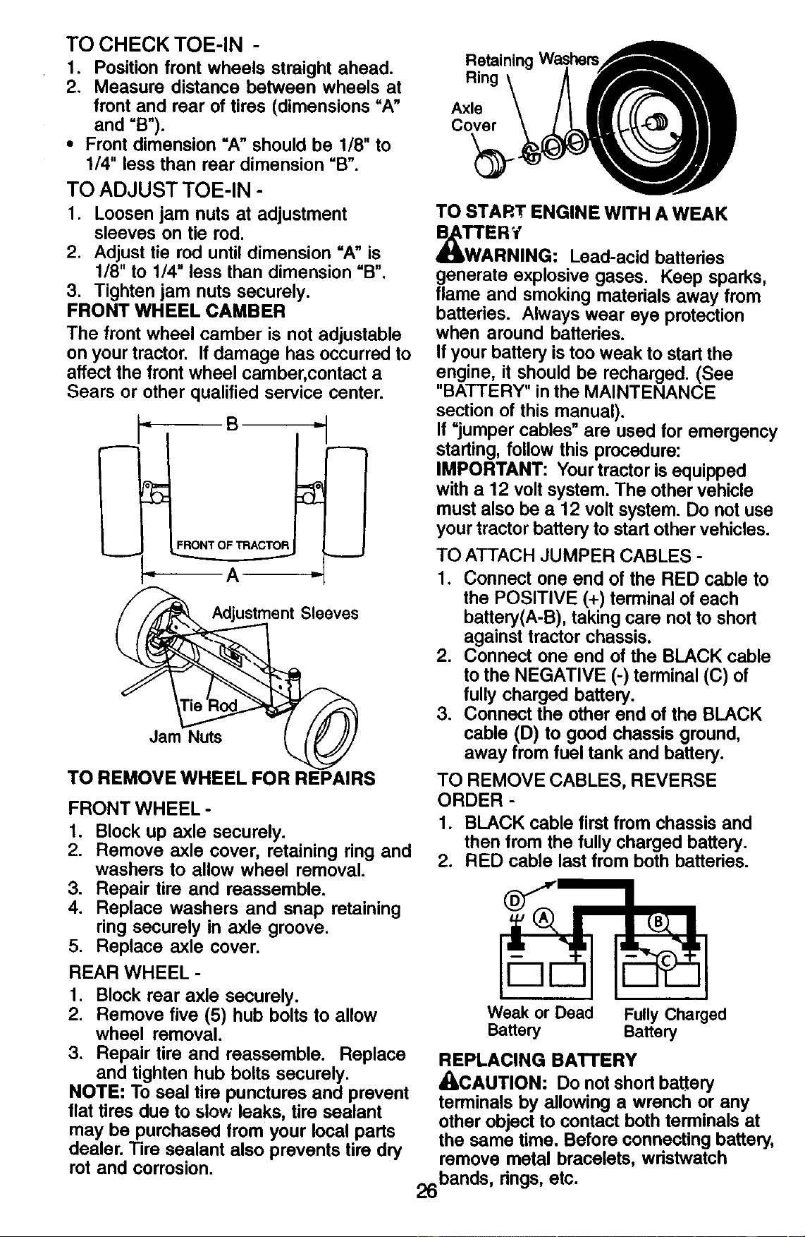
BELT INSTALLATION -
1. Place V part of belt into grooves on
engine pulley and front V-idler,
making sure to route belt inside of belt
keepers.
2. Put belt coming from V-idler above
midspan belt keeper, then onto
clutching idler pulleys as shown.
3. Make sure V part of belt engages V-
idler.
4. Place belt around transaxle pulley,
beginning at top.
V part of belt should engage transaxle
pulley.
5. Place long lower section of belt
through loop in midspan belt keeper.
6. Check to be sure belt is on proper
side of all belt keepers.
7. Reinstall mower drive belt onto
electric clutch pulley.
IMPORTANT: Check Brake Adjustment.
Clutching Flat Idler
Engine Above
Belt
Keeper
n I Belt Transaxle
___Engin_ Twists Belt Pulley
A Pulle_ Keeper
_j._V-ldler
"_I_=_As Viewed from Bottom
TO ADJUST STEERING WHEEL ALIGN-
MENT
If steering wheel crossbars are not
horizontal (left to right) when wheels are
positioned straight forward, remove
steenng wheel and reassemble with
crossbar horizontal. Tighten securely.
FRONT WHEEL TOE-IN ADJUSTMENT
Front wheel toe-in is required for proper
steering operation. Toe-in was set at the
factory and adjustment should not be
necessary. If parts in the front axle or
steenng mechanism have been replaced
or damaged, check toe-in and adjust if
25necessary.
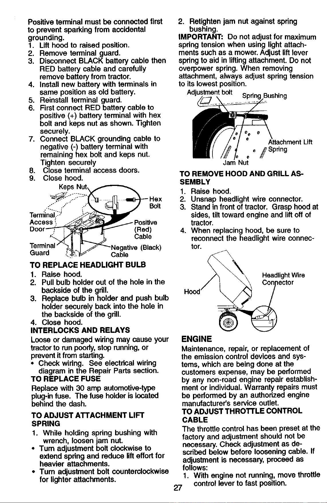
TO CHECK TOE-IN -
1. Position front wheels straight ahead.
2. Measure distance between wheels at
front and rear of tires (dimensions "A"
and "B").
• Front dimension =A" should be 1/8" to
1/4" less than rear dimension "B".
TO ADJUST TOE-IN -
1. Loosen jam nuts at adjustment
sleeves on tie rod.
2. Adjust tie rod until dimension "A" is
1/8" to 1/4" less than dimension "B".
3. Tighten jam nuts securely.
FRONT WHEEL CAMBER
The front wheel camber is not adjustable
on your tractor. If damage has occurred to
affect the front wheel camber, contact a
Sears or other qualified service center.
"t
Adjustment Sleeves
Jam Nuts
TO REMOVE WHEEL FOR REPAIRS
FRONT WHEEL -
1. Block up axle securely.
2. Remove axle cover, retaining ring and
washers to allow wheel removal.
3. Repair tire and reassemble.
4. Replace washers and snap retaining
ring securely in axle groove.
5. Replace axle cover.
REAR WHEEL -
1. Block rear axle securely.
2. Remove five (5) hub bolts to allow
wheel removal.
3. Repair tire and reassemble. Replace
and tighten hub bolts securely.
NOTE: To seal tire punctures and prevent
flat tires due to slow leaks, tire sealant
may be purchased from your local parts
dealer. Tire sealant also prevents tire dry
rot and corrosion.
Retaining Washers
Ring
Axle
Cover
TO START ENGINE WITH A WEAK
_W'_ ERY
ARNING: Lead-acid batteries
generate explosive gases. Keep sparks,
flame and smoking materials away from
batteries. Always wear eye protection
when around batteries.
If your battery is too weak to start the
engine, it should be recharged. (See
"BATTERY" in the MAINTENANCE
section of this manual).
If "jumper cables" are used for emergency
starting, follow this procedure:
IMPORTANT: Your tractor is equipped
with a 12 volt system. The other vehicle
must also be a 12 volt system. Do not use
your tractor battery to start other vehicles.
TO ATTACH JUMPER CABLES -
1. Connect one end of the RED cable to
the POSITIVE (+) terminal of each
battery(A-B), taking care not to short
against tractor chassis.
2. Connect one end of the BLACK cable
to the NEGATIVE (-) terminal (C) of
fully charged battery.
3. Connect the other end of the BLACK
cable (D) to good chassis ground,
away from fuel tank and battery.
TO REMOVE CABLES, REVERSE
ORDER -
1. BLACK cable first from chassis and
then from the fully charged battery.
2. RED cable last from both batteries.
Weak or Dead Fully Charged
Battery Battery
REPLACING BATTERY
_CAUTION: Do not short battery
terminals by allowing a wrench or any
other object to contact both terminals at
the same time. Before connecting battery,
remove metal bracelets, wristwatch
26bands, dngs, etc.
Positive terminal must be connected first
to prevent sparking from accidental
grounding.
1. Lift hood to raised position.
2. Remove terminal guard.
3. Disconnect BLACK battery cable then
RED battery cable and carefully
remove battery from tractor.
4. Install new battery with terminals in
same position as old battery.
5. Reinstall terminal guard.
6. First connect RED battery cable to
positive (+) battery terminal with hex
bolt and keps nut as shown. Tighten
securely.
7. Connect BLACK grounding cable to
negative (-) battery terminal with
remaining hex bolt and keps nut.
Tighten securely
8. Close terminal access doors.
9. Close hood.
Bolt
(Red)
Cable
Guard
Cable
(Black)
TO REPLACE HEADLIGHT BULB
1. Raise hood.
2. Pull bulb holder out of the hole in the
backside of the grill.
3. Replace bulb in holder and push bulb
holder securely back into the hole in
the backside of the grill.
4. Close hood.
INTERLOCKS AND RELAYS
Loose or damaged wiring may cause your
tractor to run poorly, stop running, or
prevent it from starting.
• Check wiring. See electrical wiring
diagram in the Repair Parts section.
TO REPLACE FUSE
Replace with 30 amp automotive-type
plug-in fuse. The fuse holder is located
behind the dash.
TO ADJUST ATTACHMENT LIFT
SPRING
1. While holding spdng bushing with
wrench, loosen jam nut.
• Turn adjustment bolt clockwise to
extend spring and reduce lift effort for
heavier attachments.
• Tum adjustment bolt counterclockwise
for lighter attachments.
2. Retighten jam nut against spring
bushing.
IMPORTANT: Do not adjust for maximum
spdng tension when using light attach-
ments such as a mower. Adjust lift lever
spring to aid in lifting attachment. Do not
overpower spring. When removing
attachment, always adjust spring tension
to its lowest position.
Adjustmentbolt
Attachment Lift
_ /Spring
TO REMOVE HOOD AND GRILL AS-
SEMBLY
1. Raise hood.
2. Unsnap headlight wire connector.
3. Stand in front of tractor. Grasp hood at
sides, tilt toward engine and lift off of
tractor.
4. When replacing hood, be sure to
reconnect the headlight wire connec-
tor.
Headlight Wire
lector
ENGINE
Maintenance, repair, or replacement of
the emission control devices and sys-
tems, which are being done at the
customers expense, may be performed
by any non-road engine repair establish-
ment or individual. Warranty repairs must
be performed by an authorized engine
manufacturer's service outlet.
TO ADJUST THROTTLE CONTROL
CABLE
The throttle control has been preset at the
factory and adjustment should not be
necessary. Check adjustment as de-
scribed below before loosening cable. If
adjustment is necessary, proceed as
follows:
1. With engine not running, move throttle
control lever to fast position.
27
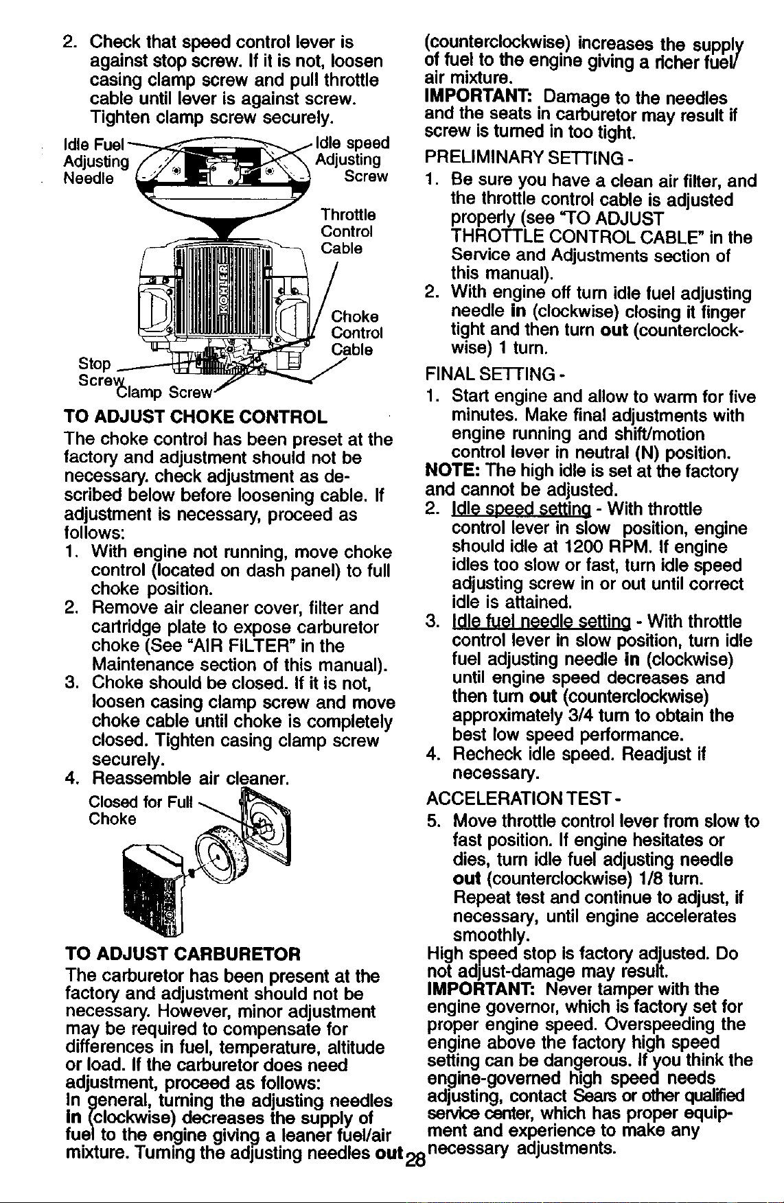
2. Check that speed control lever is
against stop screw. If it is not, loosen
casing clamp screw and pull throttle
cable until lever is against screw.
Tighten clamp screw securely.
Idle
Adjusting Adjusting
Needle Screw
Throttle
Control
Cable
Choke
Control
Cable
Stop
Scre_lamp Screw
TO ADJUST CHOKE CONTROL
The choke control has been preset at the
factory and adjustment should not be
necessary, check adjustment as de-
scribed below before loosening cable. If
adjustment is necessary, proceed as
follows:
1. With engine not running, move choke
control (located on dash panel) to full
choke position.
2. Remove air cleaner cover, filter and
cartridge plate to expose carburetor
choke (See "AIR FILTER" in the
Maintenance section of this manual).
3. Choke should be closed. If it is not,
loosen casing clamp screw and move
choke cable until choke is completely
closed. Tighten casing clamp screw
securely.
4. Reassemble air cleaner.
Closed for Full
Choke
TO ADJUST CARBURETOR
The carburetor has been present at the
factory and adjustment should not be
necessary. However, minor adjustment
(countemlockwise) increases the supply
of fuel to the engine giving a richer fuel/
air mixture.
IMPORTANT: Damage to the needles
and the seats in carburetor may result if
screw is tumed in too tight.
PRELIMINARY SETTING -
1. Be sure you have a clean air filter, and
the throttle control cable is adjusted
propedy (see "TO ADJUST
THROTTLE CONTROL CABLE" in the
Service and Adjustments section of
this manual).
2. With engine off turn idle fuel adjusting
needle in (clockwise) closing it finger
tight and then turn out (counterclock-
wise) 1 turn.
FINAL SETTING -
1. Start engine and allow to warm for five
minutes. Make final adjustments with
engine running and shift/motion
control lever in neutral (N) position.
NOTE: The high idle is set at the factory
and cannot be adjusted.
2. Idle speed setting - With throttle
control lever in slow position, engine
should idle at 1200 RPM. If engine
idles too slow or fast, turn idle speed
adjusting screw in or out until correct
idle is attained.
3. Idle fuel needle setting - With throttle
control lever in slow position, turn idle
fuel adjusting needle in (clockwise)
until engine speed decreases and
then tum out (counterclockwise)
approximately 3/4 tum to obtain the
best low speed performance.
4. Recheck idle speed. Readjust if
necessary.
ACCELERATION TEST -
5. Move throttle control lever from slow to
fast position. If engine hesitates or
dies, turn idle fuel adjusting needle
out (counterclockwise) 1/8 turn.
Repeat test and continue to adjust, if
necessary, until engine accelerates
smoothly.
High speed stop is factory adjusted. Do
not adjust-damage may result.
IMPORTANT: Never tamper with the
engine governor, which is factory set for
may be required to compensate for proper engine.,speed.. Over.speeding,the
d fferences in fuel, temperature, altitude engme aDove me [acrory ntgn speea
or load. f the carburetor does need setting can be dangerous. If you think the
adjustment, proceed as follows: en.gine-govemed, high speeo needs...
In Qeneral, tuming the adjusting needles aojusung, comacl. _:_ars or omer qualmeo
In (clockwise) decreases the supply of sennce center, whtch has proper equtp-
fuel to the engine giving a leaner fuel/air ment and ex .pe.nence to maKe any
mixture. Tuming the adjusting needles out28necessary adjustments.
Immediately prepare your tractor for
storage at the end of the season or if the
tractor will not be used for 30 days or
more.
_I_kCAUTION: Never store the tractor with
gasoline in the tank inside a building
where fumes may reach an open flame or
spark. Allow the engine to cool before
storing in any enclosure.
TRACTOR
Remove mower from tractor for winter
storage. When mower is to be stored for
a period of time, clean it thoroughly,
remove all dirt, grease, leaves, etc. Store
in a clean, dry area.
1. Clean entire tractor (See =CLEANING"
in the Maintenance section of this
manual).
2. Inspect and replace belts, if necessary
(See belt replacement instructions in
the Service and Adjustments section
of this manual).
3. Lubricate as shown in the Mainte-
nance section of this manual.
4. Be sure that all nuts, bolts and screws
are securely fastened. Inspect moving
parts for damage, breakage and wear.
Replace if necessary.
5. Touch up all rusted or chipped paint
surfaces; sand lightly before painting.
BATrERY
• Fully charge the battery for storage.
• After a pedod of time in storage, battery
may require recharging.
• To help prevent corrosion and power
leakage dudng long pedods of storage,
battery cables should be disconnected
and battery cleaned thoroughly (see
"TO CLEAN BATTERY AND TERMI-
NALS" in the Maintenance section of
this manual).
• After cleaning, leave cables discon-
nected and place cables where they
cannot come in contactwith battery
terminals.
• If battery is removed from tractor for
storage, do not store battery directly on
concrete or damp surfaces.
ENGINE
FUEL SYSTEM
IMPORTANT: It is important to prevent
gum deposits from forming in essential
fuel system parts such as carburetor, fuel
hose, or tank during storage. Also,
alcohol blended fuels (called gasohol or
using ethanol or methanol) can attract
moisture which leads to separation and
formation of acids during storage. Acidic
gas can damage the fuel system of an
engine while in storage.
1. Drain the fuel tank.
2. Start the engine and let it run until the
fuel lines and carburetor are empty.
• Never use engine or carburetor cleaner
products in the fuel tank or permanent
damage may occur.
• Use fresh fuel next season.
NOTE: Fuel stabilizer is an acceptable
altemative in minimizing the formation of
fuel gum deposits during storage. Add
stabilizer to gasoline in fuel tank or
storage container. Always follow the mix
ratio found on stabilizer container. Run
engine at least 10 minutes after adding
stabilizer to allow the stabilizer to reach
the carburetor. Do not drain the gas tank
and carburetor if using fuel stabilizer.
ENGINE OIL
Drain oil (with engine warm) and replace
with clean engine oil. (See =ENGINE" in
the Maintenance section of this manual).
CYLINDER(S)
1. Remove spark plug(s).
2. Pour one ounce of oil through spark
plug hole(s) into cylinder(s).
3. Turn ignition key to start position for a
few seconds to distribute oil.
4. Replace with new spark plug(s).
OTHER
• Do not store gasoline from one season
to another.
• Replace your gasoline can if your can
starts to rust. Rust and/or dirt in your
gasoline will cause problems.
• If possible, store your tractor indoors
and cover it to give protection from dust
and dirt.
• Cover your tractor with a suitable
protective cover that does not retain
moisture. Do not use plastic. Plastic
cannot breathe which allows conden-
sation to form and will cause your
tractor to rust.
IMPORTANT: Never cover tractor while
engine and exhaust areas are still warm.
29
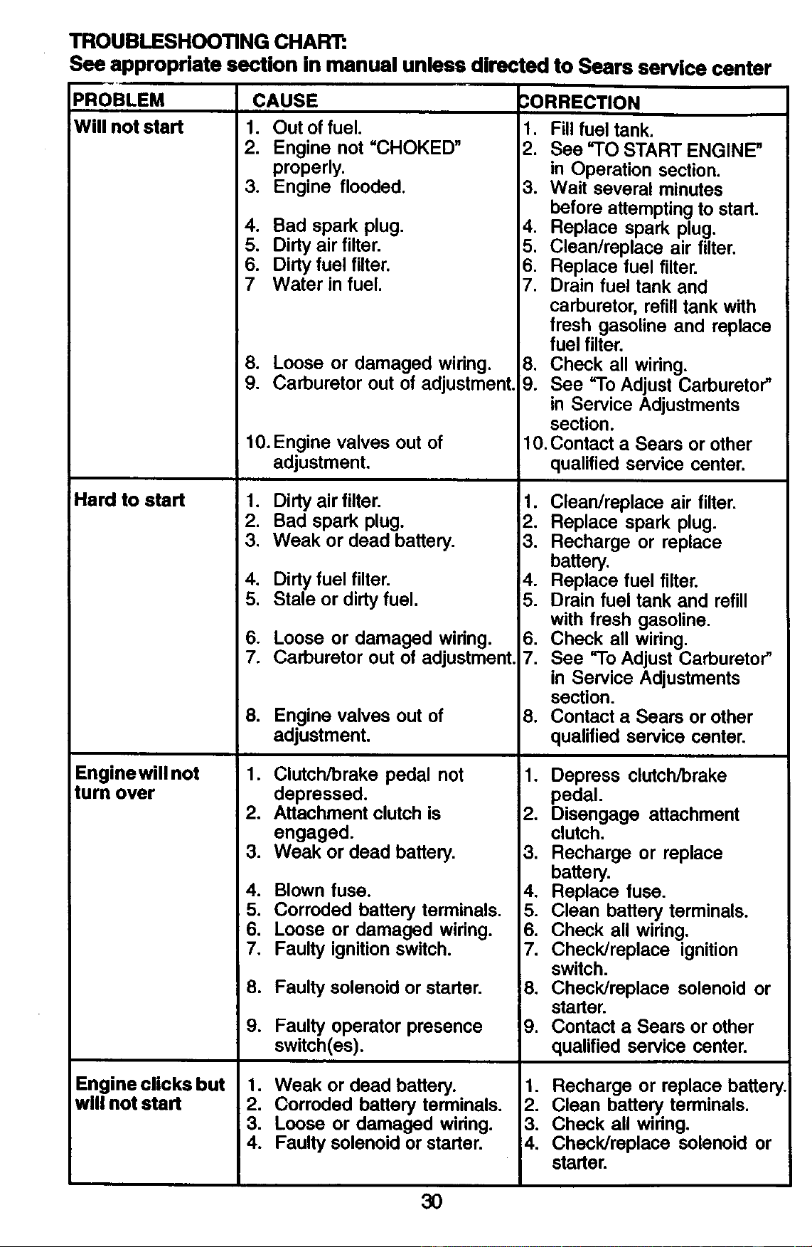
TROUBLESHOOTING CHART:
See appropriate section in manual unless directed to Sears service center
PROBLEM CAUSE
Will not start 1. Out of fuel.
2. Engine not =CHOKED"
properly,
3. Engine flooded.
Hard to start
Enginewill not
turn over
4. Bad spark plug.
5. Dirty air filter.
6. Dirty fuel filter.
7 Water in fuel.
8. Loose or damaged wiring.
9. Carburetor out of adjustment.
10. Engine valves out of
adjustment.
1. Dirty air filter.
2. Bad spark plug.
3. Weak or dead battery.
.
5.
.
7.
.
.
CORRECTION
1. Fill fuel tank.
2. See "TO START ENGINE"
in Operation section.
3. Wait several minutes
before attempting to start.
4. Replace spark plug.
5. Clean/replace air filter.
6. Replace fuel filter.
7. Drain fuel tank and
carburetor, refill tank with
fresh gasoline and replace
fuel filter,
8. Check all wiring.
9. See =1"oAdjust Carburetor"
in Service Adjustments
section.
10. Contact a Sears or other
qualified service center.
Engine clicks but
will not start
!1.
i2.
.
Dirty fuel filter, i4.
Stale or dirty fuel. 15.
Loose or damaged wiring. 6.
Carburetor out of adjustment. 7.
Engine valves out of 8.
adjustment.
Clutch/brake pedal not 1.
Clean/replace air filter.
Replace spark plug.
Recharge or replace
battery.
Replace fuel filter.
Drain fuel tank and refill
with fresh gasoline.
Check all wiring.
See "To Adjust Carburetor"
in Service Adjustments
section.
Contact a Sears or other
qualified service center.
Depress clutch/brake
depressed.
2. Attachmentclu_his
engaged.
3. Weak ordead battery.
4. Blown fuse.
pedal.
2. Disengage attachme_
clu_h.
3. Recharge or replace
battery.
4. Replace fuse.
5. Corroded battery terminals.
6. Loose or damaged widng.
7. Faulty ignition switch.
8. Faulty solenoid or starter.
.
Faulty operator presence
switch(es).
1. Weak or dead battery.
2. Corroded battery terminals.
3. Loose or damaged wiring.
4. Faulty solenoid or starter.
5. Clean battery terminals.
6. Check all wiring.
7. Check/replace ignition
switch.
8. Check/replace solenoid or
starter.
9. Contact a Sears or other
qualified service center.
1. Recharge or replace battery
2. Clean battery terminals.
3. Check all widng.
4. Check/replace solenoid or
starter.
30
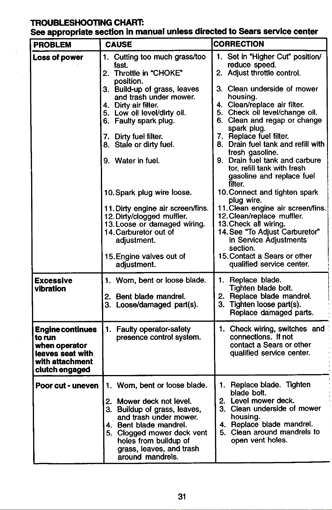
TROUBLESHOOTING CHART:
See appropriate section in manual unless directed to Sears service center
PROBLEM
LOSSof power
Excessive
vibration
Enginecontinues
torun
when operator
leaves seat with
with attachment
clutch engaged
CAUSE CORRECTION
Poor cut - uneven
1. Cutting too much grass/too
fast.
2. Throttle in "CHOKE"
position.
3. Build-up of grass, leaves 3.
and trash under mower.
4. Dirty air filter. 4.
5. Low oil level/dirty oil. 5.
6. Faulty spark plug. 6.
7. Dirty fuel filter. 7.
8. Stale or dirty fuel. 8.
9. Water in fuel. 9.
10.Spark plug wire loose.
11.Dirty engine air screen/fins.
12. Dirty/clogged muffler.
13. Loose or damaged wiring.
14.Carburetor out of
adjustment.
15. Engine valves out of
adjustment.
_1. Worn, bent or loose blade. 1.
2. Bent blade mandrel. 2.
3. Loose/damaged part(s). 3.
1. Faulty operator-safety 1.
presence control system.
1. Wom, bent or loose blade. 1.
2. Mower deck not level. 2.
3. Buildup of grass, leaves, 3.
and trash under mower.
4. Bent blade mandrel. 4.
5. Clogged mower deck vent 5.
holes from buildup of
grass, leaves, and trash
around mandrels.
1. Set in "Higher Cut" position/
reduce speed.
2. Adjust throttle control.
Clean underside of mower
housing.
Clean/replace air filter.
Check oil leveVchange oil.
Clean and regap or change
spark plug.
Replace fuel filter.
Drain fuel tank and refill with
fresh gasoline.
Drain fuel tank and carbure
tor, refill tank with fresh
gasoline and replace fuel
filter.
10. Connect and tighten spark
plug wire.
11. Clean engine air screen/fins.
12. Clean/replace muffler.
13.Check all wiring.
14. See _lo Adjust Carburetor"
in Service Adjustments
section.
15.Contact a Sears or other
qualified service center.
Replace blade.
Tighten blade bolt.
Replace blade mandrel.
Tighten loose part(s).
Replace damaged pads.
Check wiring, switches and
connections. If not
contact a Sears or other
qualified service center.
Replace blade. _ghten
blade bolt.
Level mower deck.
Clean underside of mower
housing.
Replace blade mandrel.
Clean around mandrels to
open vent holes.
31
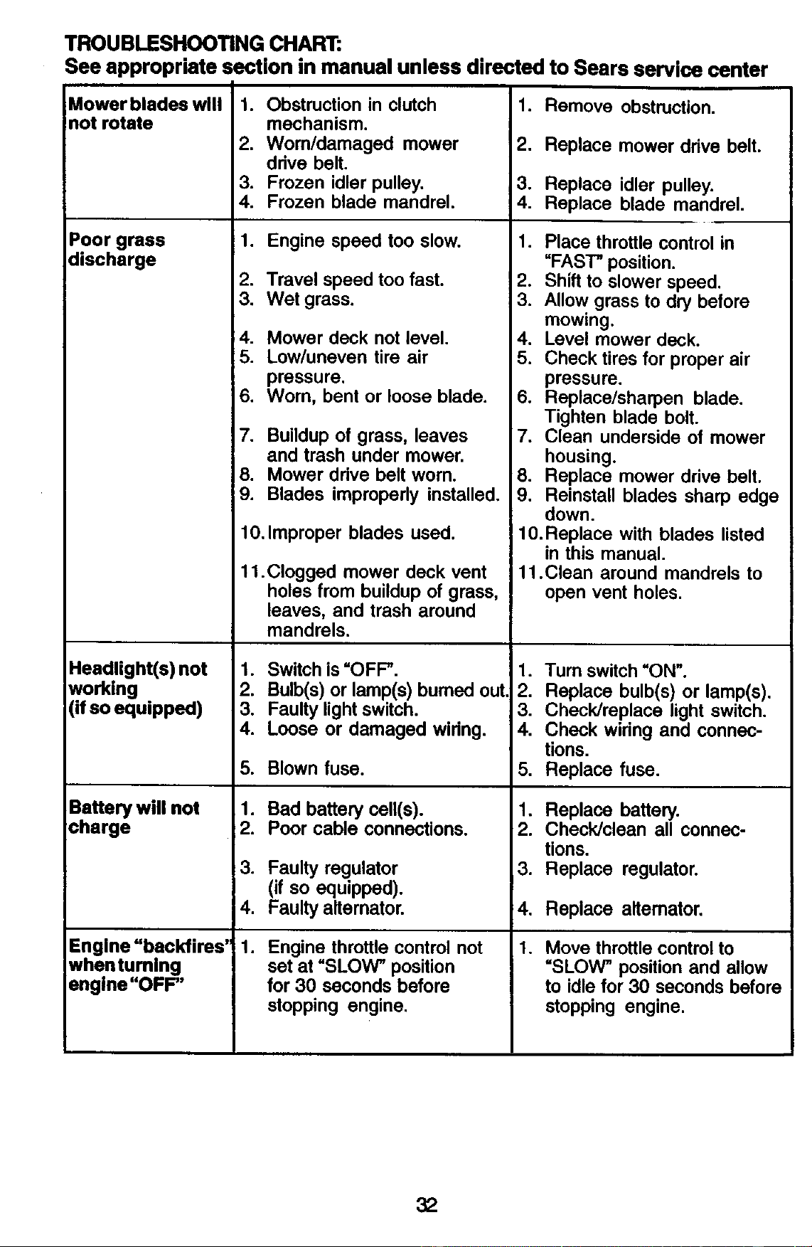
TROUBLESHOOTING CHART:
See appropriate section in manual unless directed to Sears service center
Mower blades will
not rotate
Poor grass
discharge
1. Obstruction in clutch
mechanism.
2. Wom/damaged mower
drive belt.
3. Frozen idler pulley.
4. Frozen blade mandrel.
1. Engine speed too slow.
1. Remove obstruction.
2. Replace mower ddve belt.
3. Replace idler pulley.
4. Replace blade mandrel.
1. Place throttle control in
=FAST" position.
2. Travel speed too fast.
3. Wet grass.
4. Mower deck not level.
5. Low/uneven tire air
pressure.
2. Shift to slower speed.
3. Allow grass to dry before
mowing.
4. Level mower deck.
5. Check tires for proper air
pressure.
6. Worn, bent or loose blade.
Headlight(s) not
working
(if so equipped)
Battery will not
charge
Engine "backfires'
whentuming
engine "OFF"
7. Buildup of grass, leaves
and trash under mower.
8. Mower drive belt worn.
9. Blades improperly installed.
10. Improper blades used.
11 .Clogged mower deck vent
holes from buildup of grass,
leaves, and trash around
mandrels.
1. Switchis=OFF".
2. Bulb(s)or lamp(s) bumed out
3. Faulty lightswitch.
4. Loose or damaged widng.
5. Blown fuse.
1. Bad battery cell(s).
2. Poor cable connections.
3. Faulty regulator
(if so equipped).
4. Faulty alternator.
6. Replace/sharpen blade.
Tighten blade bolt.
7. Clean underside of mower
housing.
8. Replace mower drive belt.
9. Reinstall blades sharp edge
down.
10. Replace with blades listed
in this manual.
11.Clean around mandrels to
open vent holes.
1. Turn switch =ON".
2. Replace bulb(s) or lamp(s).
3. Check/replace light switch.
4. Check widng and connec-
tions.
5. Replace fuse.
1. Replace battery.
2. Check/clean all connec-
tions.
3. Replace regulator.
.
Engine throttle control not
set at uSLOW" position
for 30 seconds before
stopping engine.
,
1.
Replace alternator,
Move throttle control to
=SLOW" position and allow
to idle for 30 seconds before
stopping engine.
32
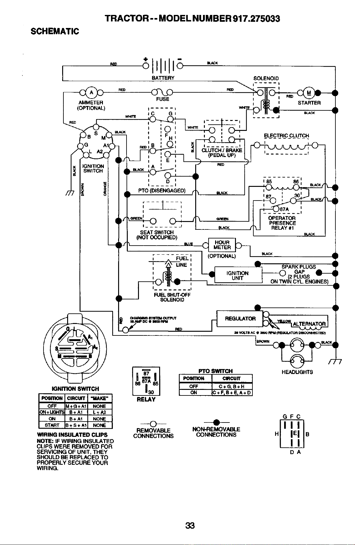
SCHEMATIC
TRACTOR - - MODEL NUMBER 917.275033
AMMETER
(OPTIONAL)
IGNITION SWITCH
WIRING INSULATED CUPS
NOTE: IF WIRING INSULATED
CLIPS WERE REMOVED FOR
SERVICING OF UNIT, THEY
SHOULD BE REPLACED TO
PROPERLY SECURE YOUR
WIRING,
FUSE
BATTERY SOLENOID
RE D _i I
I
t
(PEDAL UP)
t
i
i
i i STARTER
ELECTRIC CLUTCH
I
185 86
SEAT SWITCH
(NOT OCCUPIED)
I
il
OPERATOR
PRESENCE
RELAY #1
(OPTIONAL)
LINE I
I
I
.t
FUELSHUT-OFF
SOLENOID
SPARK PLUGS
IGNITION GAP
UNIT .)PLUGS
RELAY
Fro SWITCH
PO_RION CIRCUIT
OFF C+GrS+H
ON C+FrB+ErA+D
HEADLIGHTS
O "--'e--
REMOVABLE NON-REMOVABLE
CONNECTIONS CONNECTIONS
GFC
DA
33
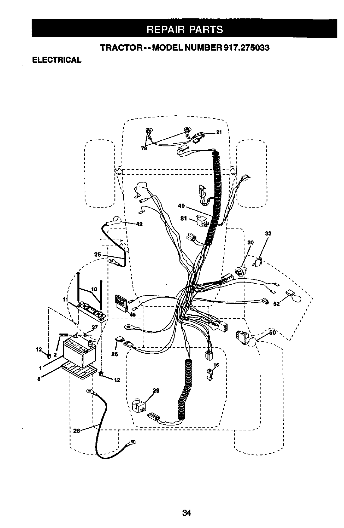
TRACTOR- - MODEL NUMBER 917.275033
ELECTRICAL
I
I
I
I
34
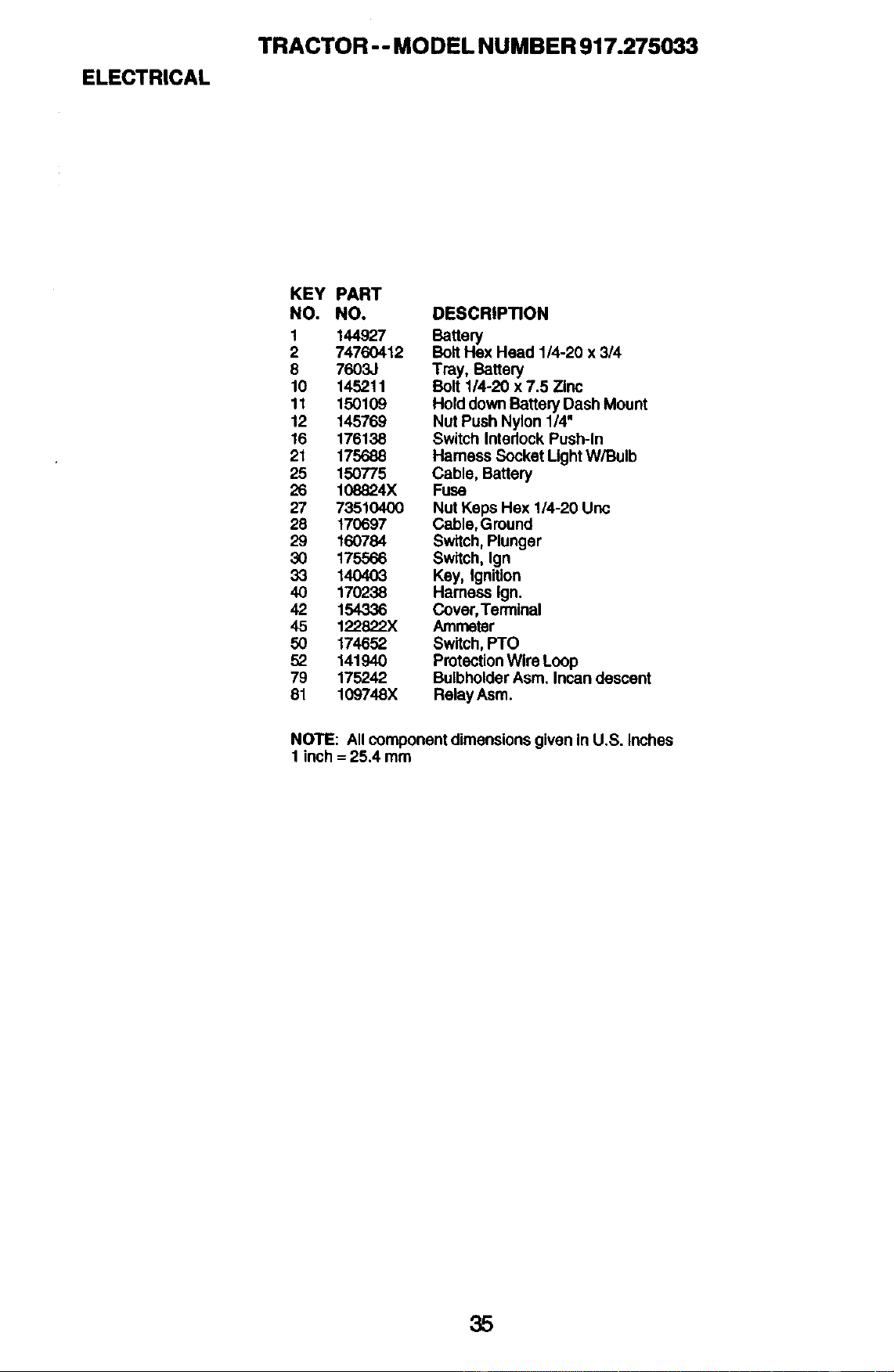
ELECTRICAL
TRACTOR -- MODEL NUMBER 917.275033
KEY PART
NO. NO. DESCRIPTION
1 144927 Battery
2 74760412 BollHex Head 1/4-20 x 3/4
8 7603J Tray, Battery
10 145211 BOIl 114-20x7.5 Zinc
11 150109 HolddownBatteryDashMount
12 145769 NutPushNylon1/4"
16 176138 SwitchInterlockPush-In
21 175688 Hamess SocketLightW/Bulb
25 150775 Cable, Battery
26 108824X Fuse
27 73510400 NutKepsHex 1/4-20 Unc
28 170697 Cable,Ground
29 160784 Switch,Plunger
30 175566 Switch,Ign
33 140403 Key, Ignition
40 170238 Hamese Ign.
42 154336 Cover,Terminal
45 122822X Ammeter
50 174652 Switch,PTO
52 141940 ProtectionWireLoop
79 175242 BulbholderAsm.Incandescent
81 109748X RelayAsm.
NOTE: AllcomponentdimensionsgiveninU.S. Inches
1 inch= 25.4 mm
35
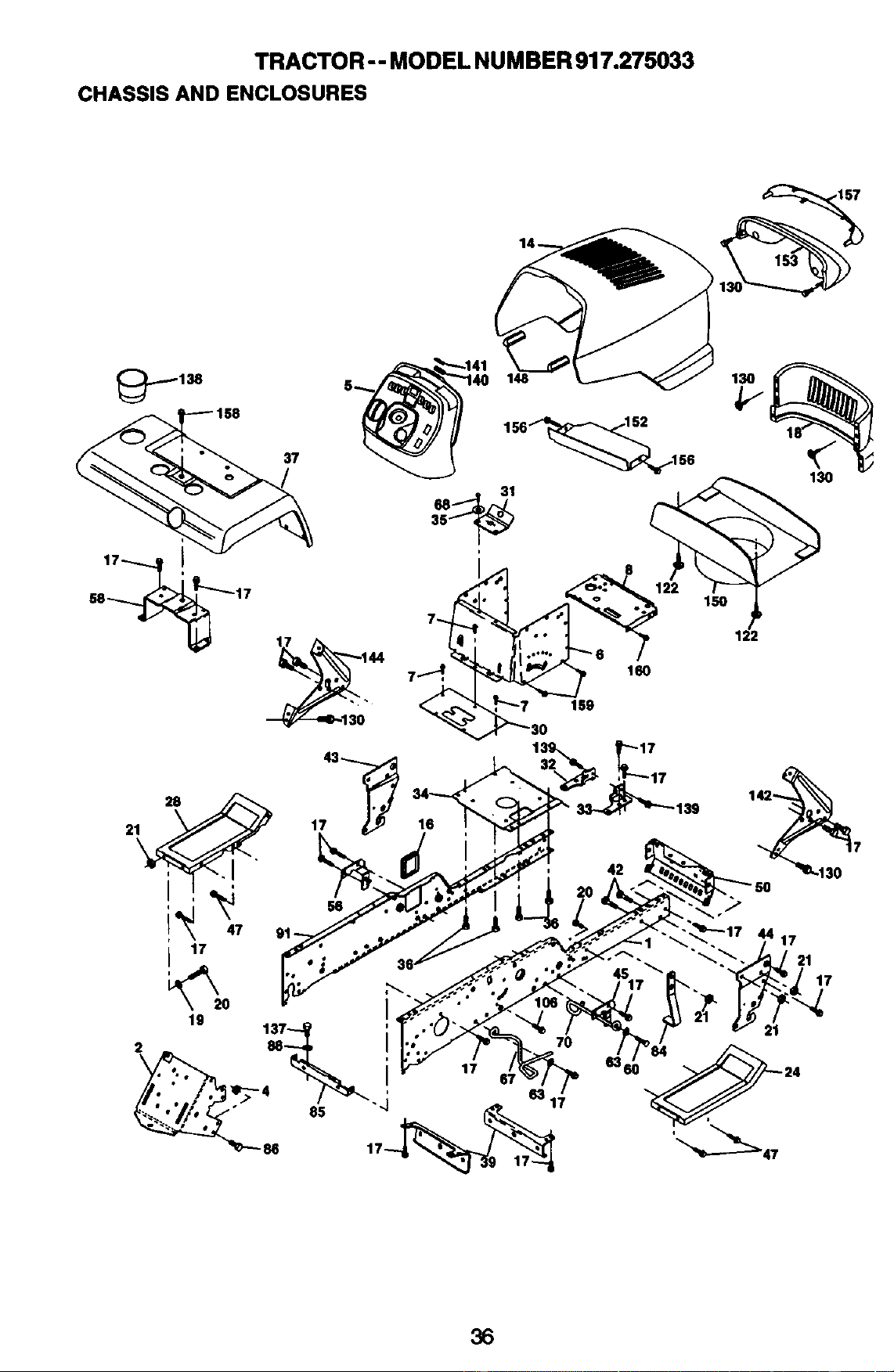
TRACTOR -- MODEL NUMBER 917.275033
CHASSIS AND ENCLOSURES
36
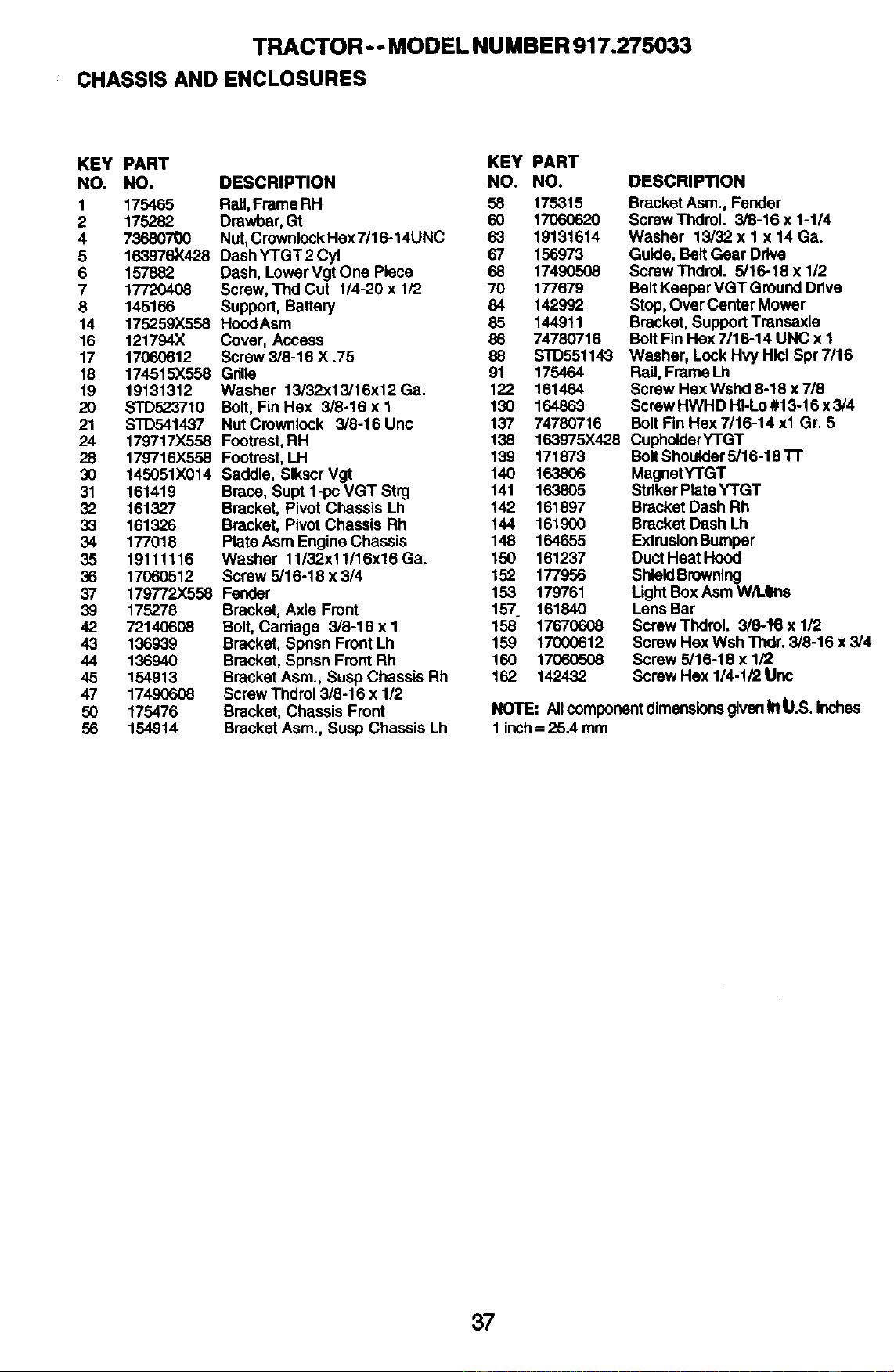
TRACTOR -- MODEL NUMBER 917.275033
CHASSIS AND ENCLOSURES
KEY PART KEY PART
NO. NO. DESCRIPTION NO. NO.
1 175465 Rail, Frame RH 58 175315
2 175282 Drawbar, Gt 60 17060620
4 73680700 Nut, Crownlock Hex 7/16-14UNC 63 19131614
5 163976)(428 Dash YTGT 2 Cyl 67 156973
6 157882 Dash, Lower Vgt One Piece 68 17490508
7 17720408 Screw, Thd Cut 1/4-20 x 1/2 70 177679
8 145166 Support, Battery 84 142992
14 175259X558 Hood Asm 85 144911
16 121794X Cover, Access 86 74780716
17 17060612 Screw 3/6-16 X .75 88
18 174515X558 Gnlle 91
19 19131312 Washer 13/32x13/16x12 Ga. 122
20 STD523710 Bolt, FinHex 3/8-16xl 130
21 STD541437 Nut Crownicck 3/8-16 Unc 137
24 179717X558 Footrest, RH 138
28 179716X558 Footrest, LH 139 171873
30 145051X014 Saddle, SIkscr Vgt 140 163806
31 161419 Brace, Supt 1-pc VGT Strg 141 163805
32 161327 Bracket, Pivot Chassis Lh 142 161897
33 161326 Bracket, Pivot Chassis Rh 144 161900
34 177018 Plate Asm Engine Chassis 148 164655
35 19111116 Washer 11/32x11/16x16Gao 150 161237
36 17060512 Screw 5/16-18 x 3/4 152 177956
37 179772X558 Fender 153 179761
39 175278 Bracket, Axle Front 157 161840
42 72140608 Bolt, Carriage 3/8-16 x I 158" 17670608
43 136939 Bracket, Spnsn Front Lh 159 17000612
44 136940 Bracket, Spnsn Front Rh 160 17060508
45 154913 Bracket Asm., Susp Chassis Rh 162 142432
47 17490608 Screw Thdrol 3/8-16 x 1/2
50 175476 Bracket, Chassis Front
56 154914 Bracket Asm., Susp Chassis Lh
DESCRIPTION
BracketAsm.,Fender
ScrewThdrol. 3/8-16 x 1-1/4
Washer 13/32 x I x 14 Ga.
Guide,BeltGearDrive
ScrewThdrol. 5/16-18 x 1/2
BeltKeeperVGT GroundDrive
Stop,Over CenterMower
Bracket,SupportTransaxle
Bolt FinHex 7/16-14 UNC x I
STD551143 Washer, Lock Hvy Hlcl Spr 7/16
175464 Rail, Frame Lh
161464 Screw Hex Wshd 8-18 x 7/8
164863 Screw HWHD Hi-Lo #13-16 x 3/4
74780716 Bolt Fin Hex 7/16-14 xl Gr. 5
163975X428 CupholderY-I'GT
BoltShoulder5/16-181-1"
MagnetYTGT
StrikerRate YTGT
BracketDashRh
BracketDash Lh
ExtrusionBumper
DuctHeat Hood
ShieldBrowning
LightBoxAsmW/Lens
LensBar
ScrewThdroL 3/8-16 x 1/2
ScrewHex Wsh Thdr. 3/8-16 x 3/4
Screw5/16-18 x 1/2
ScrewHex 1/4-1/2 Unc
NOTE: Allcomponentdimensionsgiven1!1t,I.S.Inches
1 Inch= 25.4 mm
37
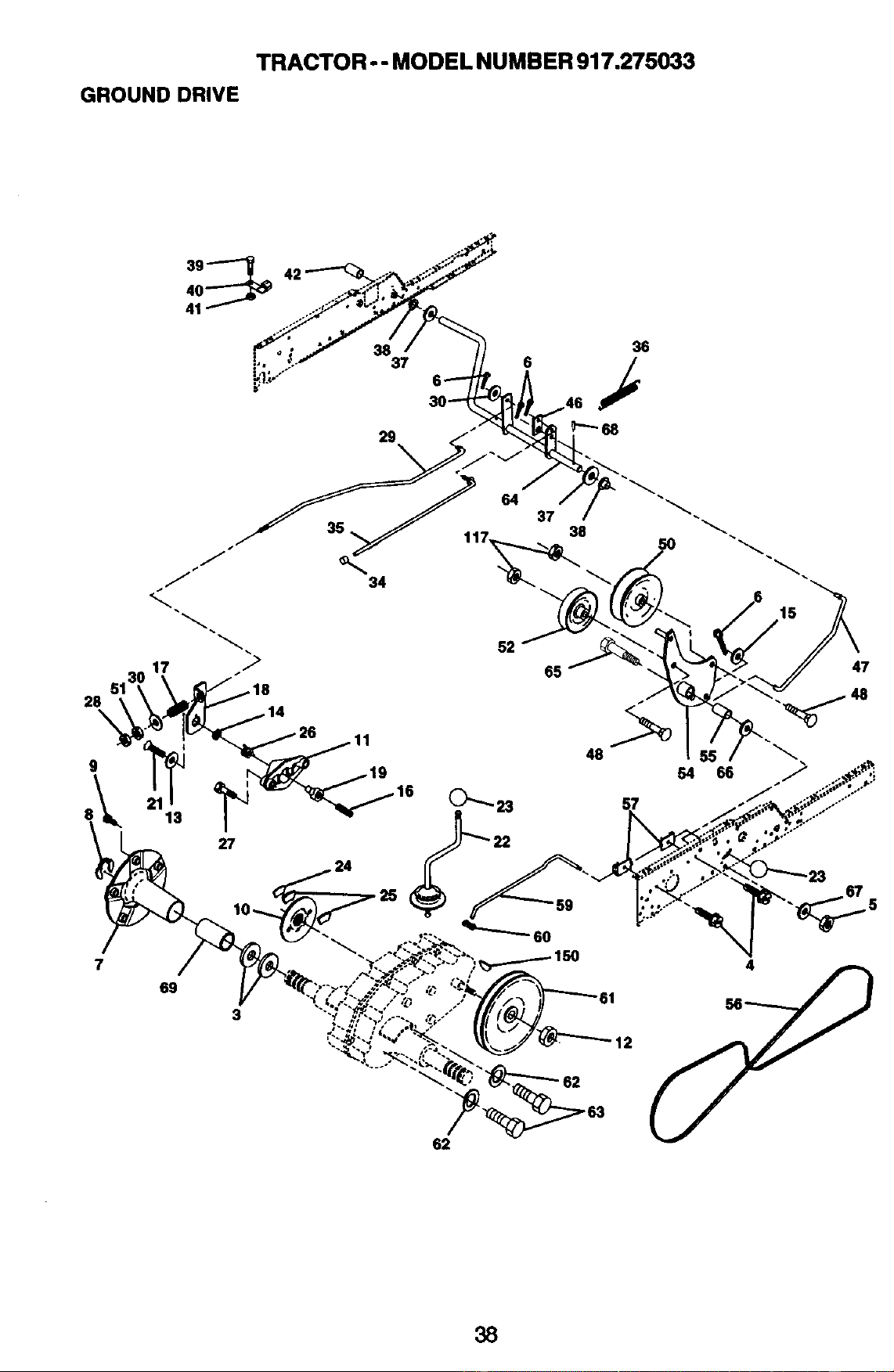
TRACTOR - - MODE L NUMBER 917.275033
GROUND DRIVE
28
\
9
7
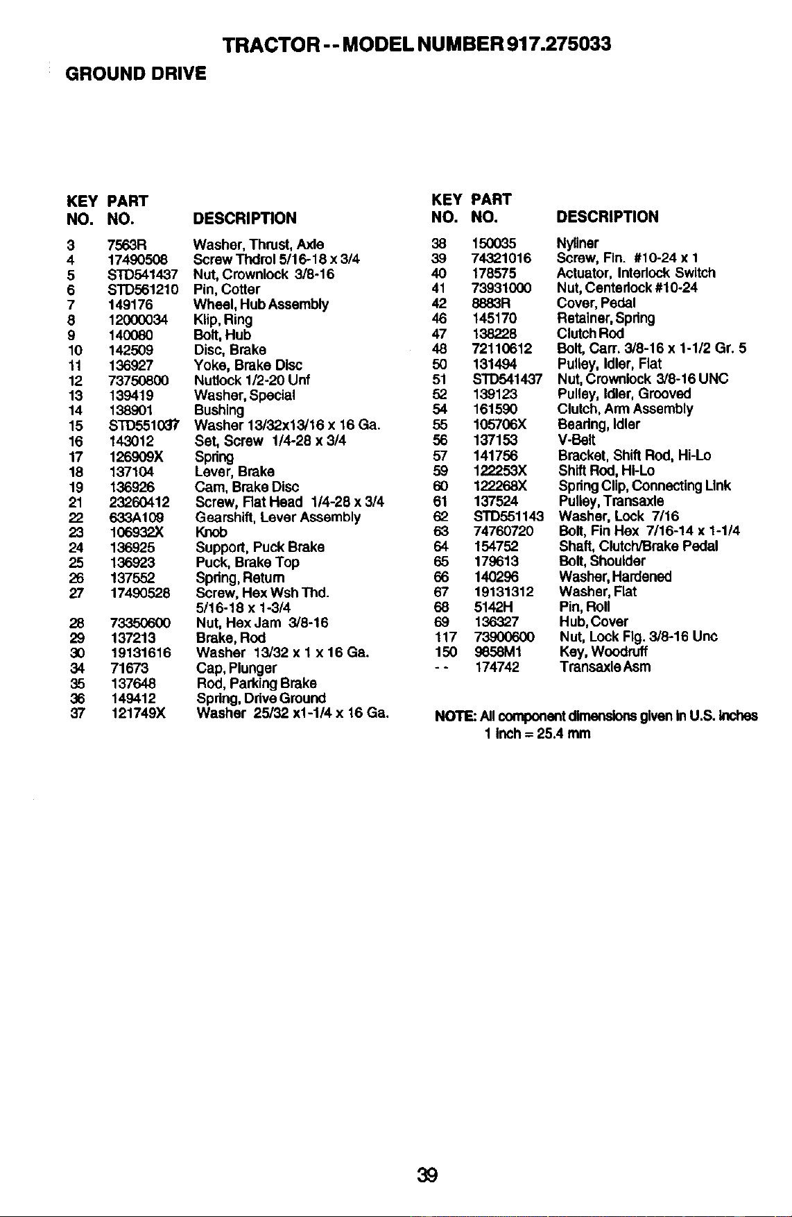
TRACTOR -- MODEL NUMBER 917.275033
GROUND DRIVE
KEY PART KEY PART
NO. NO. DESCRIPTION NO. NO. DESCRIPTION
3 7563R Washer, Thrust, Axle 38 150035
4 17490508 Screw Thdro15116-18 x 314 39 74321016
5 STD541437 Nut, Crownlock 3/8-16 40 178575
6 STD561210 Pin, Cotter 41 73931000
7 149176 Wheel, Hub Assembly 42 8883R
8 12000034 Klip, Ring 46 145170
9 140080 Bolt, Hub 47 138228
10 142509 Disc, Brake 48 72110612
11 136927 Yoke, Brake Disc 50 131494
12 73750800 Nutlock 1/2-20 Unf 51 S'rD541437
13 139419 Washer, Special 52 139123
14 138901 Bushing 54 161590
15 STD551037 Washer 13/32.x13,'16 x 16 Ga. 55 105706X
16 143012 Set, Screw 1/4-28 x 3/4 56 137153
17 126909X Spring 57 141756
18 137104 Lever, Brake 59 122253X
19 136926 Cam, Brake Disc 60 122268X
21 23260412 Screw, Rat Head 1/4-28 x 3/4 61 137524
22 633A10_ Gearshift, Lever Assembly 62
23 106932X Knob 63 74760720
24 136925 Support, Puck Brake 64 154752
25 136923 Puck, Brake Top 65 179613
26 137552 Spdng, Retum 66 140296
27 17490528 Screw, Hex Wsh Thd. 67 19131312
5/16-18 x 1-3/4 68 5142H
28 73350600 Nut, Hex Jam 3/8-16 69 136,327
29 137213 Brake, Rod 117 73900600
30 19131616 Washer 13/32 x 1 x 16 Ga. 150 9658M1
34 71673 Cap, Plunger - - 174742
35 137648 Rod, Parking Broke
36 149412 Spring, Ddve Ground
37 121749X Washer 25/32 x1-1/4 x 16 Ga.
Nyliner
Screw,Fin. #10-24 x 1
Actuator,InterlockSwitch
Nut,Centadock#10-24
Cover,Pedal
Retainer,Spring
ClutchROd
Bolt, Carr. 3/8-16 x 1-1/2 Gr. 5
Pulley,Idler,Flat
Nut,Crownlock3/8-16 UNC
Pulley,Idler,Grooved
Clutch,ArmAssembly
Beadng,Idler
V-Belt
Bracket,ShiftRod,Hi-Lo
ShiftRod,HI-Lo
SpringClip,ConnectingLink
Pulley,Transaxle
STD551143 Washer, Look 7/16
Bolt, FinHax 7/16-14 x 1-1/4
Shaft,Clutch/BrakePedal
Bolt,Shoulder
Washer,Hardened
Washer,Rat
Pin,Roll
Hub,Cover
Nut, Lock Fig.3/8-16 Unc
Key,Woodruff
TransaxleAsm
NOTE:AllcomponentdimensionsgivenInU.S. Inches
1 inch= 25.4 mm
39
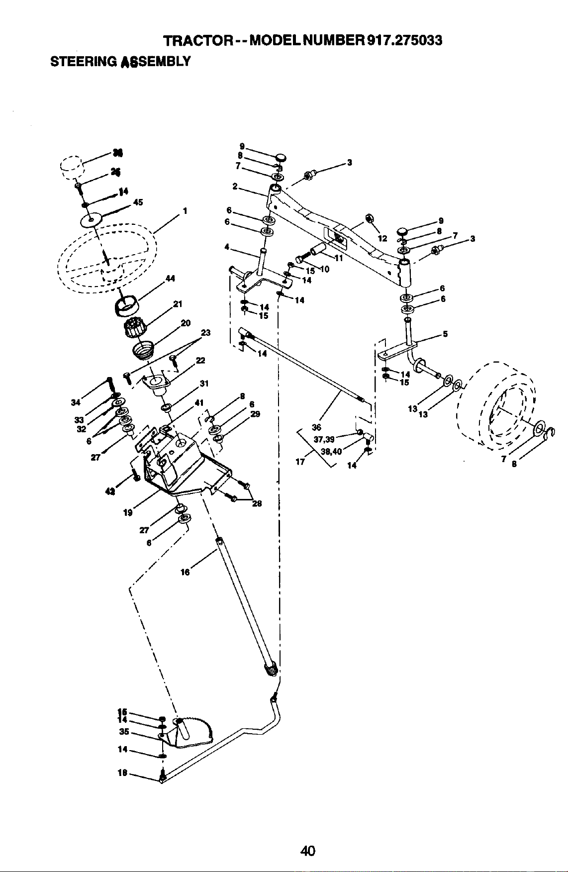
TRACTOR - - MODEL NUMBER 917.275033
STEERINGA6SEMBLY
21
23
22
34
32
27
19
27
i / /
16
/
<"
\
\
\
\
\
\
i \
14
14
15
I
,40" ,/_'
14
1313"
40
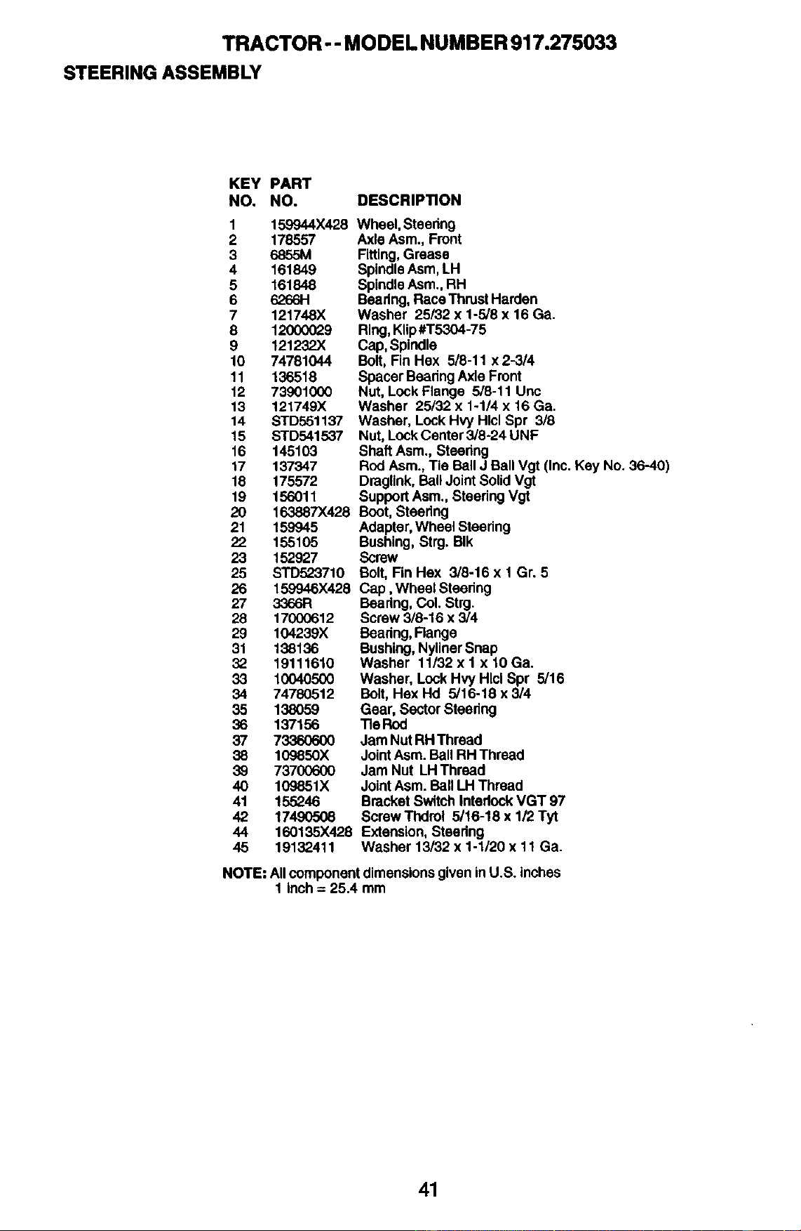
TRACTOR - - MODEL NUMBER 917.275033
STEERINGASSEMBLY
KEY PART
NO. NO.
1 159944X428
2 178557
3 6855M
4 161849
5 161848
6 6266H
7 121748X
8 12000029
9 121232X
10 74781044
11 136518
12 79901000
13 121749X
14 STD551137
15 STD541537
16 145103
17 137347
18 175572
19 156011
20 163887X428
21 159945
22 155105
23 152927
25 STD523710
26 159946X428
27 3366R
28 17000612
29 104239X
31 138136
32 19111610
33 10040500
34 74780512
35 138O59
36 137156
37 7336O6O0
38 109850X
39 73700600
40 109851X
41 155246
42 17490508
44 160135X428
45 19132411
DESCRIPTION
Wheel,Steenng
AxleAsm.,Front
Fitting,Grease
SpindleAsm,LH
SpindleAsm.,RH
Beadng,RaceThrustHarden
Washer 25/32 x 1-5/8 x 16 Ga.
Ring,Klip#T5304-75
Cap,Spindle
Bolt,Fin Hex 5/8-11 x 2-3/4
SpacerBeadngAxleFront
Nut, LockFlange 5/8-11 Uric
Washer 25/32 x 1-1/4 x 16 Ga.
Washer, LockHvy HlclSpr 3/8
Nut, LockCenter3/8-24 UNF
ShaftAsm.,Steedng
Rod Asm.,Tie BallJ BallVgt (Inc. Key No. 36-40)
Draglink,BallJointSolidVgt
SupportAsm.,SteeringVgt
Boot,Steering
Adapter,WheelSteedng
Bushing,Strg.BIk
Screw
Bolt,Fin Hex 3/8-16 x 1 Gr. 5
Cap, Wheel Steedng
Bearing,Col. Strg.
Screw3/8-16 x 3/4
Baadng, Range
Bushing,NylinerSnap
Washer 11/32 x 1 x 10 Ga.
Washer, LockHvyHlcl Spr 5/16
Bolt,Hex Hd 5/16-18 x 3/4
Gear, SectorSteedng
Tie Rod
Jam NutRHThread
JointAsm.Ball RH Thread
JamNut LHThread
JointAsm.Ball LH Thread
BracketSwitchIntedock VGT 97
ScrawThdrol 5/16-18 x 1/2 Tyt
Extension,Steadng
Washer 13/32x 1-1/20 x 11 Ga.
NOTE."AllcomponentdimensionsgiveninU.S. inches
1 inch= 25.4 mm
41
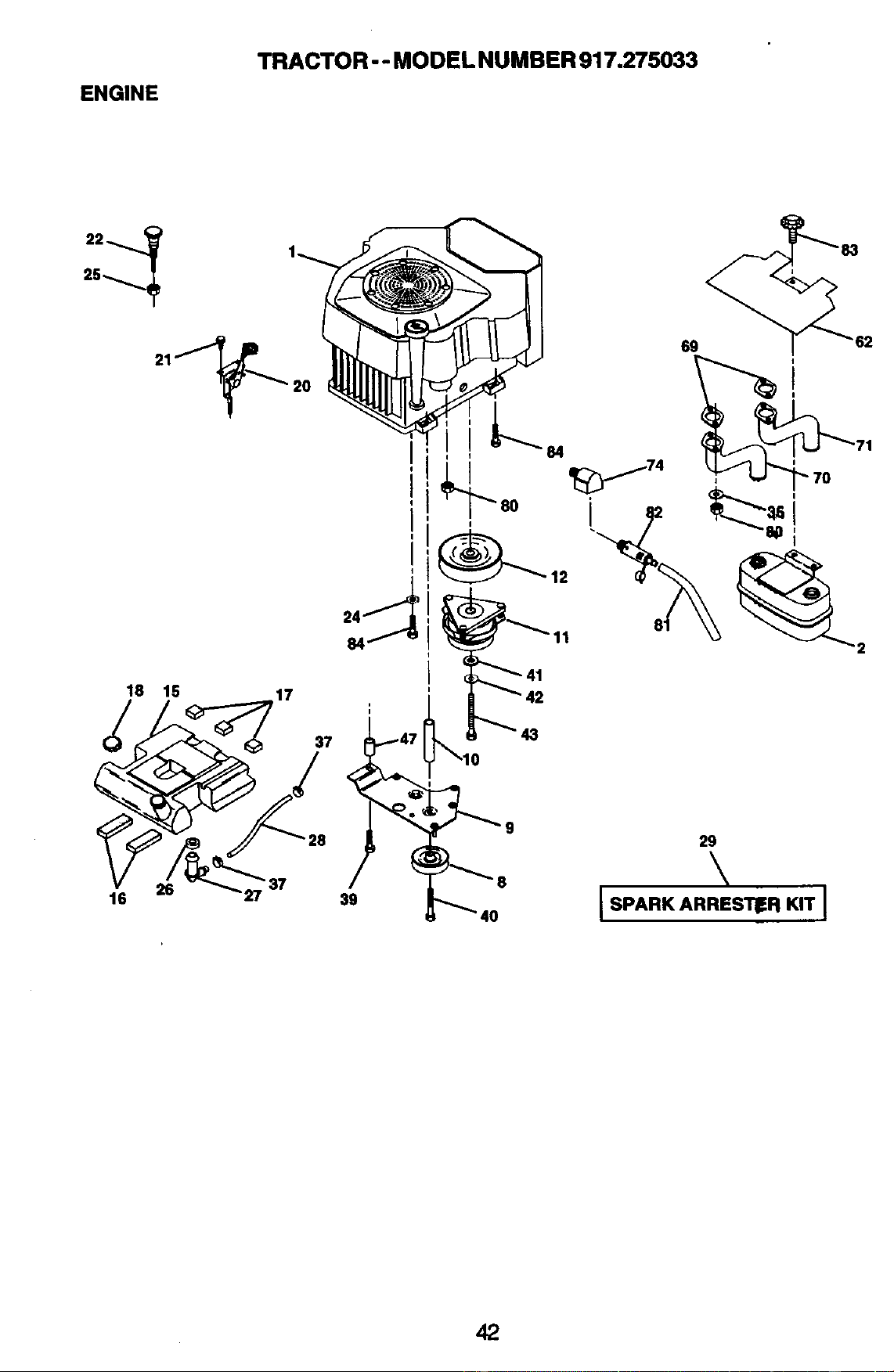
ENGINE
TRACTOR - - MODEL NUMBER 917.275033
18 15 17
41
16
26
• 37
39
29
\
IsPA.KA..ES_.K,TI
42
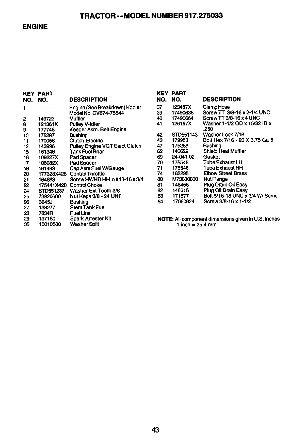
ENGINE
TRACTOR-- MODEL NUMBER 917.275033
KEY PART
NO. NO.
1 ......
2 149723
8 121361X
9 177748
10 175287
11 170056
12 143996
15 151346
16 109227X
17 1(To082X
18 161493
20 177328X428
21 164863
22 175441X428
24 S_1237
25 73920600
26 3645J
27 139277
28 7834R
29 137180
35 10010500
DESCRIPTION
KEY PART
NO. NO.
Engine(See Breakdown)Kohler 37 123487X
ModelNo.CV674-75544 39 17490636
Muffler 40 17490664
PulleyV-Idler 41 126197X
KeeperAsm.BeltEngine
Bushing 42
Clutch Electric 43 179953
PulleyEngineVGT Elect Clutch 47 175288
Tank FuelRear 62 146629
PadSpacer 69 24-041-02
PadSpacer 70 175545
CapAsmFuelW/Gauge 71 175546
Control Throttle 74 162295
ScrewHWHD Hi-Lo#13-16 x 3/4 80 M73030800
ControlChoke 81 148456
WasherExt Tooth3/8 82 148315
NutKeps3/8 - 24 UNF 83 171877
Bushing 84 17060624
StemTank Fuel
FuelLine
SparkArresterKit
WasherSplit
DESCRIPTION
ClampHose
Screw'l-I" 3/8-16 x2-1/4 UNC
Screw 1-I"3/8-16 x 4 UNC
Washer 1-1/20D x 15/32 ID x
.25O
STD551143 WasherLock7/16
Bolt Hex7/16 - 20 X 3.75 Ga 5
Bushing
ShieldHeatMuffler
Gasket
TubeExhaustLH
TubeExhaustRH
ElbowStreetBrass
NutRange
PlugDrainOil Easy
PlugOil DrainEasy
Bolt5/16-18 UNC x 3/4 W/Sems
Screw3/8-16 x 1-1/2
NOTE: AllcomponentdimensionsgiveninU.S. inches
1 inch= 25.4 mm
43
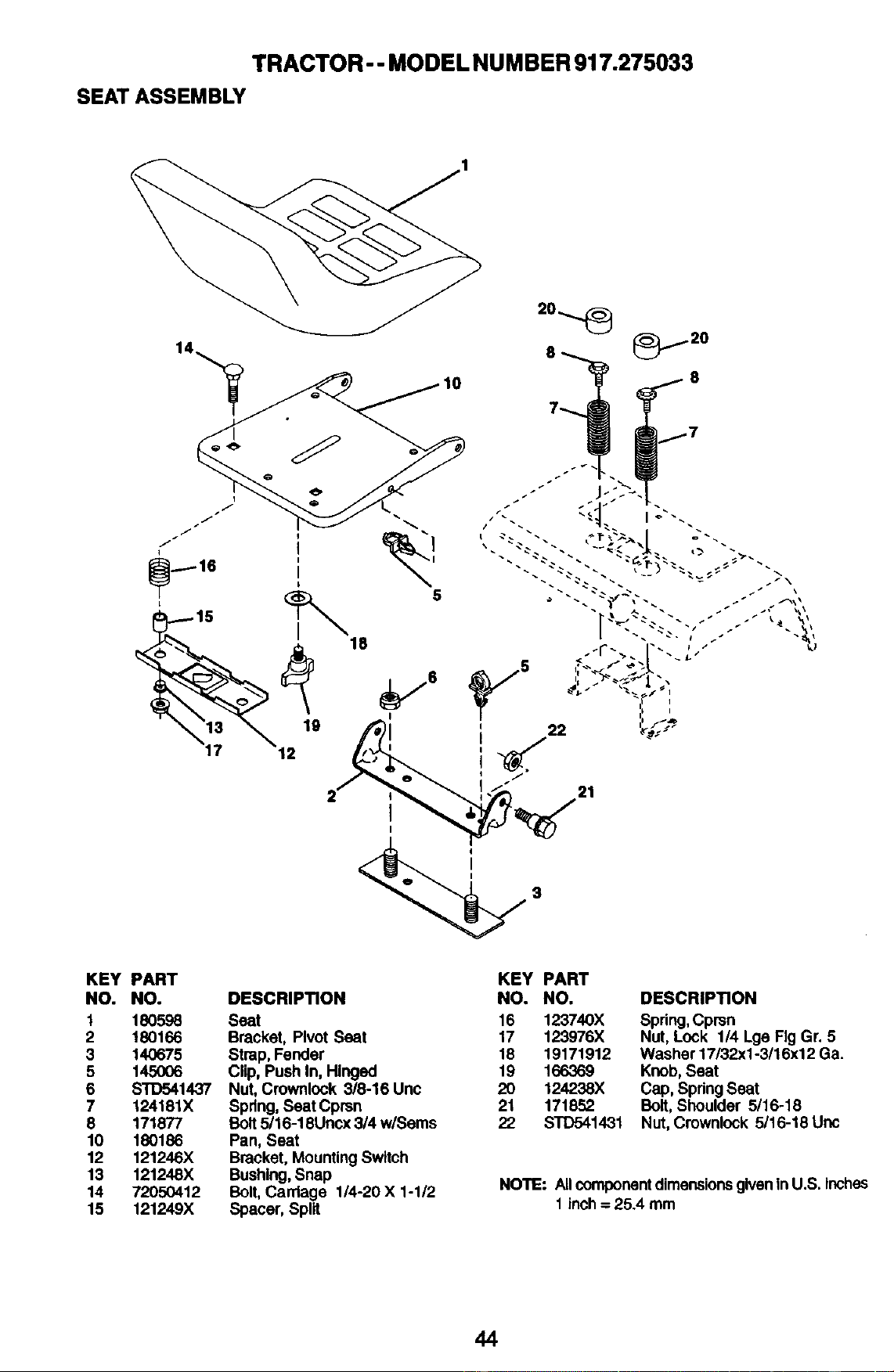
TRACTOR - - MODEL NUMBER 917.275033
SEAT ASSEMBLY
..-.---16
I
5
18
19
i2
18
I o
KEY PART
NO. NO.
1 1805.98
2 180166
3 140675
5 145OO6
6 STD541437
7 124181X
8 171877
10 180186
12 121246X
13 121248X
14 72050412
15 121249X
DESCRIPTION
Seat
Bracket, PivotSeat
Strap,Fender
Clip,PushIn, Hinged
Nut, Crownlock3/8-16 Uoc
Spring,SeatCprsn
Bolt5/I 6-18Uncx3/4 w/Seres
Pan, Seat
Bracket,MountingSwitch
Bushing,Snap
Bolt,Cardage 1/4-20X 1-1/2
Spacer,Split
KEY PART
NO. NO.
16 123740X
17 123976X
18 19171912
19 166369
20 124238X
21 171852
22 STD541431
DESCRIPTION
Spring,Cprsn
Nut, Lock 1/4 LgeFig Gr. 5
Washer17/32x1-3/16x12Ga.
Knob,Seat
Cap, SpringSeat
Bolt,Shoulder 5/16-18
Nut,Crownlock5/16-18 Unc
NOTE: All component dimensions given in U.S. Inches
1 inch = 25.4 mm
44
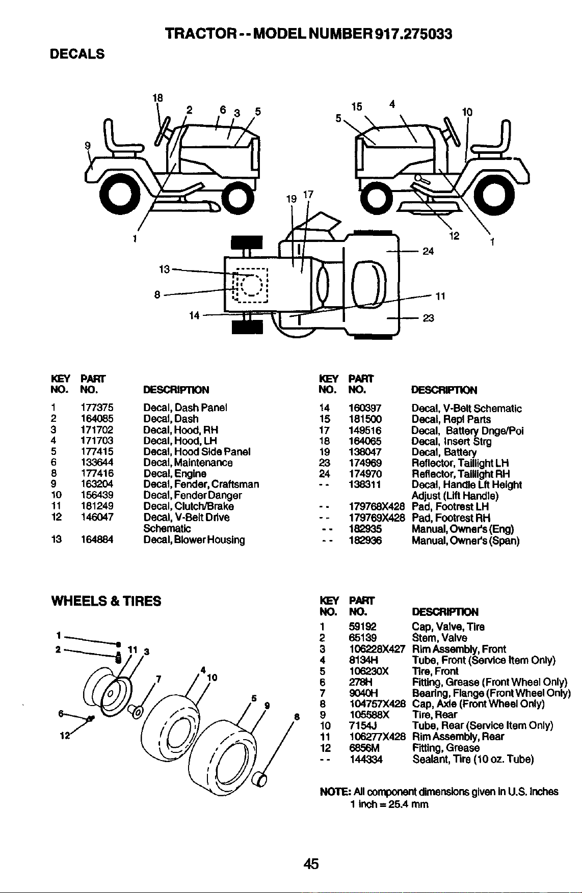
DECALS
TRACTOR - - MODEL NUMBER 917.275033
9
18
2 6
15
IO
19 17
--24
12
KI_' PARr
NO. NO.
1 177375
2 164085
3 171702
4 171703
5 177415
6 133644
8 177416
9 163204
10 156439
11 181249
12 146047
13 164884
K]EY PAFR
DESCRIPllON NO. NO. DESCRIPTION
Decal,DashPanel 14 160397
Decal,Dash 15 181500
Decal,Hood,RH 17 149516
Decal,Hood,LH 18 164065
Decal,HoodSidePanel 19 138047
Decal,Maintenance 23 174969
Decal,Engine 24 174970
Decal,Fender,Craftsman - - 138311
Decal,FenderDanger
Decal,Clutch/Broke - - 179768X428
Decal,V-BeltDrive - - 179769X428
Schematic - - 182935
Decal,BlowerHousing - - 182936
Decal,V-BeltSchematic
Decal,Repl Parts
Decal, Batten/Dnge/Poi
Decal, InsertStrg
Decal, Battery
Reflector,TaillightLH
Reflector,TaillightRH
Decal,HandleLftHeight
Adjust(LiftHandle)
Pad, FootrestLH
Pad, FootrestRH
Manual,Owner's(Eng)
Manual,Owner's(Span)
WHEELS & TIRES
3
7
5
9
6
KL=Y p/UR1"
NO. NO.
1 59192
2 65139
3 106228X427
4 8134H
5 106230X
8 278H
7 9040H
8 104757X428
9 105588X
10 7154J
11 106277X428
12 6856M
-- 144334
DESCRIP1X)N
Cap, Valve,Tire
Stem,Valve
RimAssembly,Front
Tube, Front(ServiceItemOnly)
Tire,Front
Fitting,Grease (FrontWheel Only)
Beadng,Flange(FrontWheel Only)
Cap,Axle(FrontWheelOnly)
Tire,Rear
Tube, Rear(ServiceItemOnly)
RimAssembly,Rear
Fitting,Grease
Sealant,Tire (10 oz. Tube)
NOTE: AllcomponentdimensionsgiveninU.S. Inches
1 Inch = 25.4 mm
45
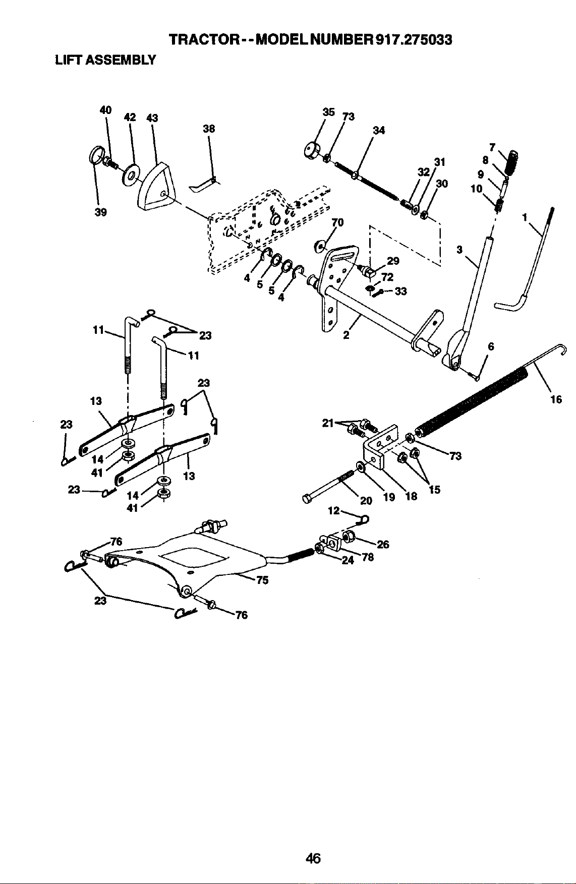
TRACTOR - - MODEL NUMBER 917.275033
LIFT ASSEMBLY
4O
42 43
39
4
35 73
34
31
32
7
9
10
1
\
23
13 i
23
2
16
21
75
46
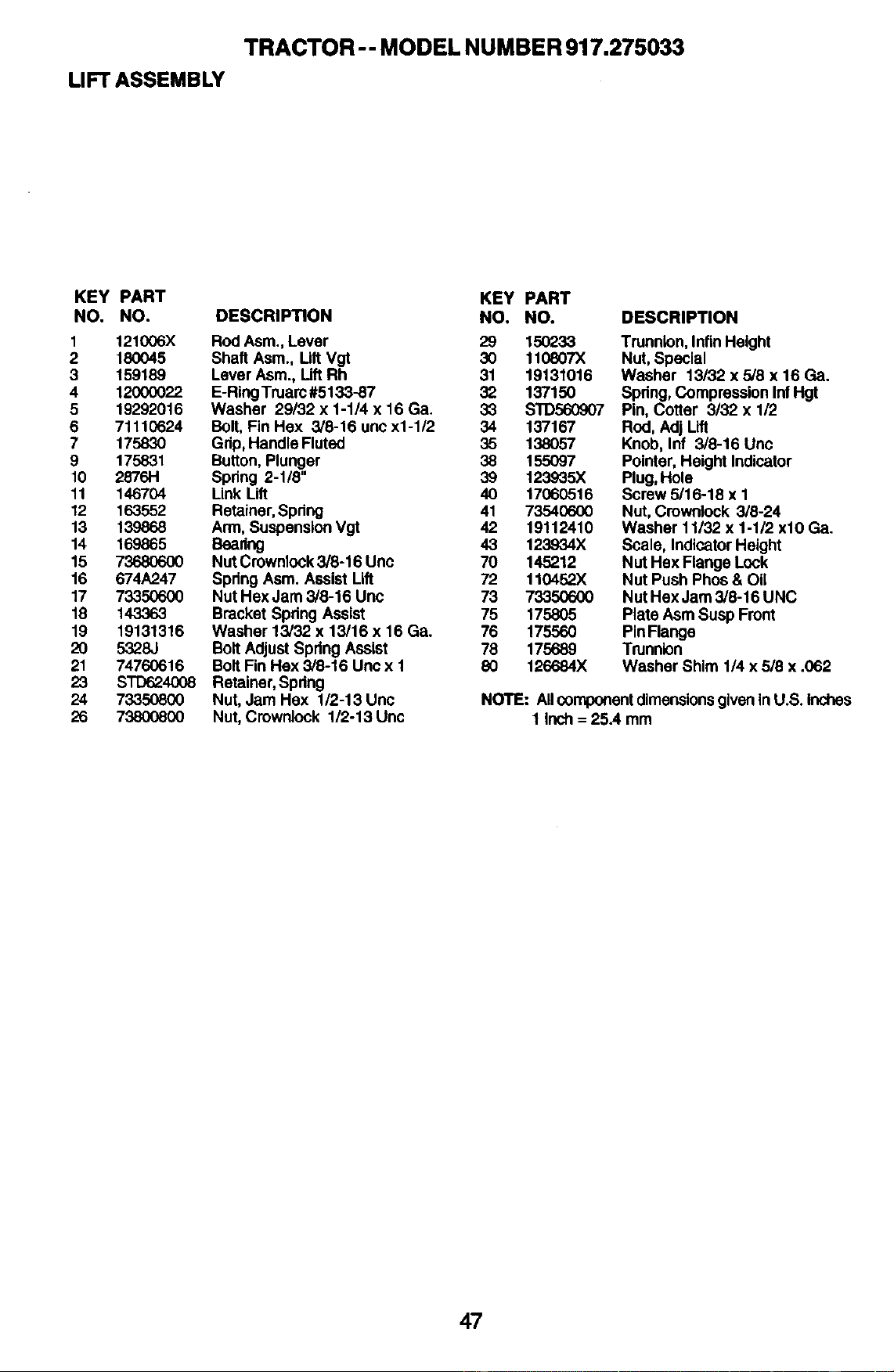
TRACTOR -- MODEL NUMBE R 917.275033
LIFT ASSEMBLY
KEY PART KEY PART
NO. NO. DESCRIPTION NO. NO.
1 121006X RodAsm., Lever 29 150233
2 180045 Shaft Asm., LiftVgt 30 110807X
3 159189 LeverAsm., lift Rh 31 19131016
4 12000022 E-RingTruarc#5133-87 32 137150
5 19292016 Washer 29/32 x 1-1/4 x 16 Ga. 33 STD560907
6 71110624 Bolt,FinHex 3/8-16 uec x1-1/2 34 137167
7 175830 Gdp,HandleFluted 35 138057
9 175831 Button,Plunger 38 155097
10 2876H Spring2-1/8" 39 123935X
11 146704 LinkLift 40 17060516
12 163552 Retainer,Spring 41 73540600
13 139868 Arm,SuspensionVgt 42 19112410
14 169865 Beadng 43 123934X
15 73680600 NutCrownlock3/8-16 Unc 70 145212
16 674A247 SpringAsm. AssistLift 72 110452X
17 73350600 Nut HexJam 3/8-16 Unc 73 73350600
18 143363 BracketSpringAssist 75 175805
19 19131316 Washer 13/32 x 13/16 x 16 Ga. 76 175560
20 5328J Bolt AdjustSpringAssist 78 175689
21 74760616 Bolt Fin Hax 3/8-16 Uncx 1 80 126684X
23 STD624008 Retainer,Spdng
24 73350800 Nut, Jam Hex 1/2-13 Unc
26 73800800 Nut,Crownlock 1/2-13 Unc
DESCRIPTION
Trunnion,InflnHeight
Nut,Special
Washer 13/32 x 5/8 x 16 Ga.
Spdng,CompressionInfHgt
Pin,Cotter 3/32 x 1/2
Rod, AdjLift
Knob,Inf 3/8-16 Uric
Pointer,Height Indicator
Plug,Hole
Screw5/16-18 x 1
Nut, Crownlock3/8-24
Washer11/32 x 1-1/2 xl0 Ga.
Scale, IndicatorHeight
NutHex FlangeLock
Nut PushPhos& Oil
NutHex Jam3/8-16 UNC
PlateAsrnSusp Front
PinFlange
Trunnion
WasherShim 1/4 x 5/8 x .062
NOTE: AllcomponentdimensionsgivenInU.S. Inches
1 Inch= 25A mm
47
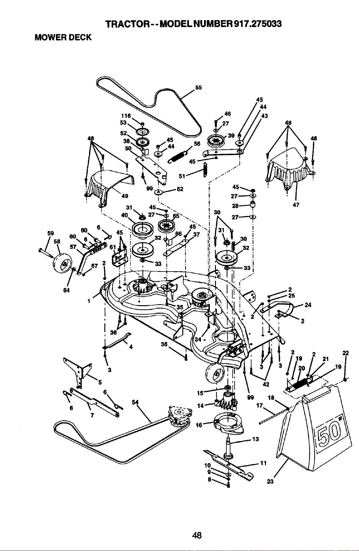
MOWER DECK
TRACTOR - - MODEL NUMBER 917.275033
59
58
116
53.,
55
45
44
43
48
47
64
1
48
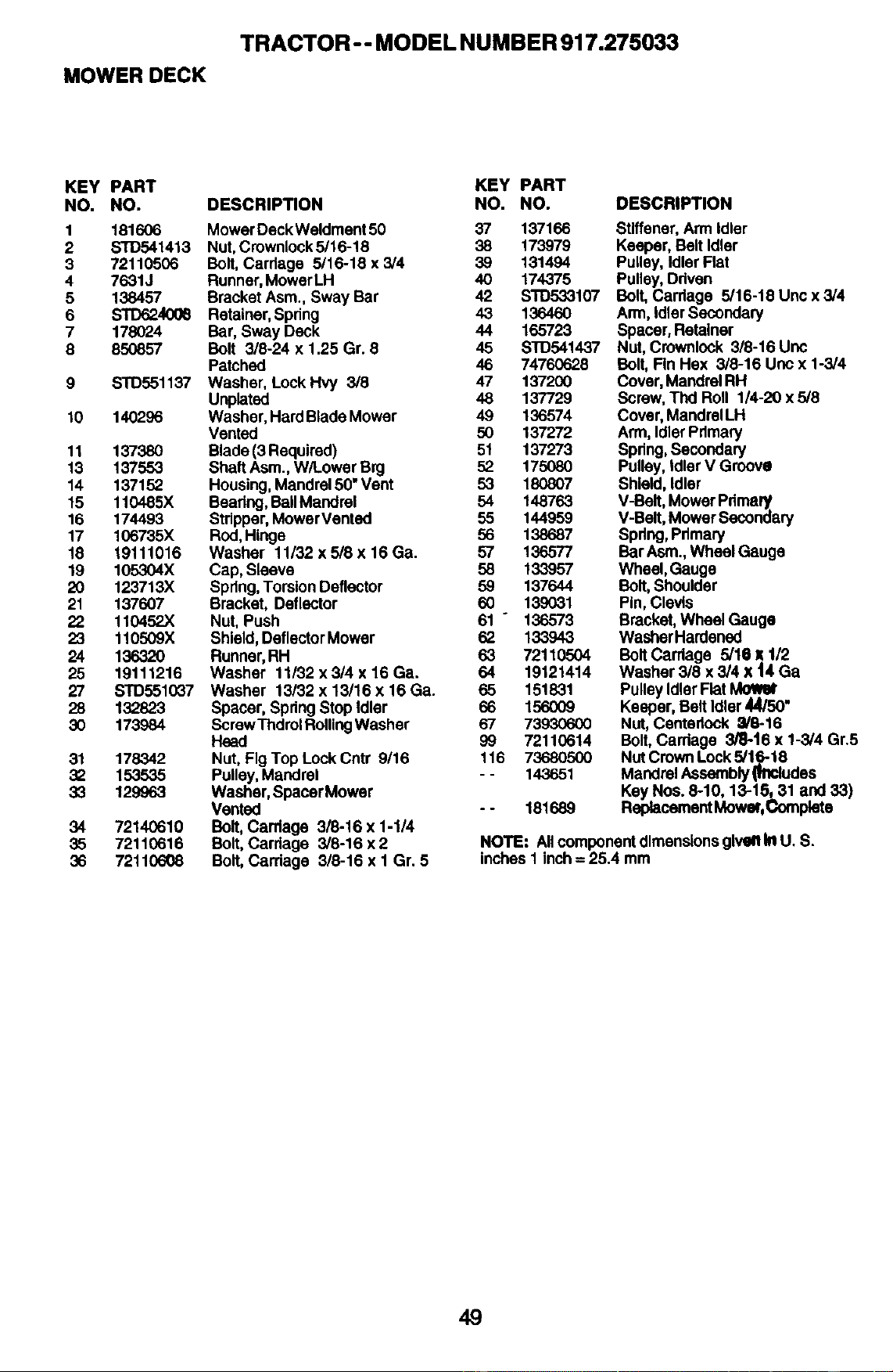
MOWER DECK
TRACTOR -- MODEL NUMBER 917.275033
KEY PART KEY PART
NO. NO. DESCRIPTION NO. NO.
1 181606 MowerDeckWeldment50 37 137166
2 STD541413 Nut,Crownlock5/16-18 38 173979
3 72110506 Bolt,Cardage 5/16-18 x 3/4 39 131494
4 7631J Runner,MowerLH 40 174375
5 138457 BracketAsm., Sway Bar 42 S'i'D533107
6 STD624006 Retainer,Spring 43 136460
7 178024 Bar, Sway Deck 44 165723
6 850857 Bolt 3/8-24 x 1.25 Gr. 8 45 STD541437
Patched 46 74760628
9 STD551137 Washer, LockHvy 3/8 47 137200
Unplated 48 137729
10 140296 Washer,HardBladeMower 49 136574
Vented 50 137272
11 137380 Blade(3 Required) 51 137273
13 137553 ShaftAsm.,W/LowerBrg 52 175080
14 137152 Housing,Mandrel50"Vent 53 180807
15 110485X Beating,BaUMandrel 54 148763
16 174493 Stripper,MowerVented 55 144959
17 106735X Rod,Hinge 56 138687
18 19111016 Washer 11/32 x 5/8 x 16 Ga. 57 136577
19 105304X Cap, Sleeve 58 133957
20 123713X Spring,TorsionDeflector 59 137644
21 137607 Bracket, Deflector 60 139031
22 110452X Nut, Push 61 ° 136573
23 110509X Shield,DeflectorMower 62 133943
24 136320 Runner,RH 63 72110504
25 19111216 Washer 11/32 x 3/4 x 16 Ga. 64 19121414
27 STD551037 Washer 13/32 x 13/16 x 16 Ga. 65 151831
28 132823 Spacer, SpringStopIdler 66 156009
30 173984 ScrewThdrolRollingWasher 67 73930600
Head 99 72110614
31 178342 Nut, Fig Top LockCntr 9/16 116 73680500
32 153535 Pulley,Mandrel - - 143651
33 129963 Washer,SpacerMower
Vented - - 181689
34 72140610 Bolt, Cardage 3/8-16 x 1-1/4
35 72110616 Bolt, Carriage 3/8-16 x 2
36 72110608 Bolt,Carriage 3/8-16 x 1 Gr. 5
DESCRIPTION
Stiffener,Arm Idler
Keeper,BeltIdler
Pulley,IdlerFlat
Pulley,Ddven
Bolt, Carriage 5/16-18 Unc x 3/4
Arm,IdlerSecondary
Spacer,Retainer
Nut, Crownlock3/8-16 Unc
Bolt, FinHex 3/8-16 Uocx 1-3/4
Cover,MandrelRH
Screw,TIxI Roll 1/4-20 x 5/8
Cover,MandrelLH
Arm,IdlerPrimary
Spring,Secondary
Pulley,IdlerV Groove
Shield,Idler
V-Belt,MowerPdmaly
V-Belt,MowerSecondary
Spring,Primary
Bar Asm.,Wheel Gauge
Wheel, Gauge
Bolt, Shoulder
Pin,Clevis
Bracket,WheelGauge
WasherHardened
BoltCarriage 5/16 x 1/2
Washer 3/8 x 3/4 x 14 Ga
PulleyIdlerFiat
Keeper,BeltIdler44/50"
Nut,Centedock _/6-16
Bolt,Cardage 3/8-16 x 1-3/4Gr.5
NutCrownLock5/16-18
MandrelAssembly_l_udes
KeyNos.8-10, 13-15_31 and 33)
ReplacementMower,Complete
NOTE: Allcomponent dimensionsgivenInU. S.
inchesI inch= 25.4 mm
49
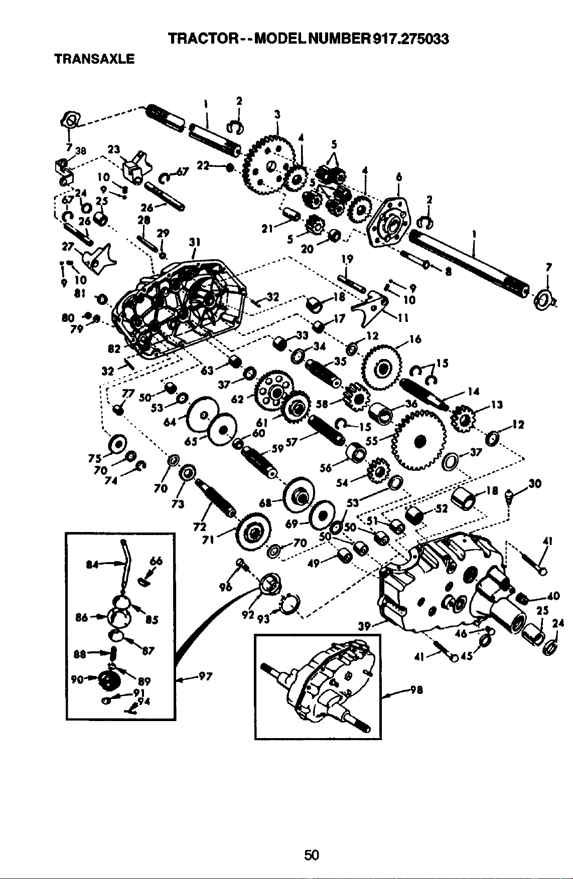
TRANSAXLE
TRACTOR - - MODEL NUMBER 917.275033
50
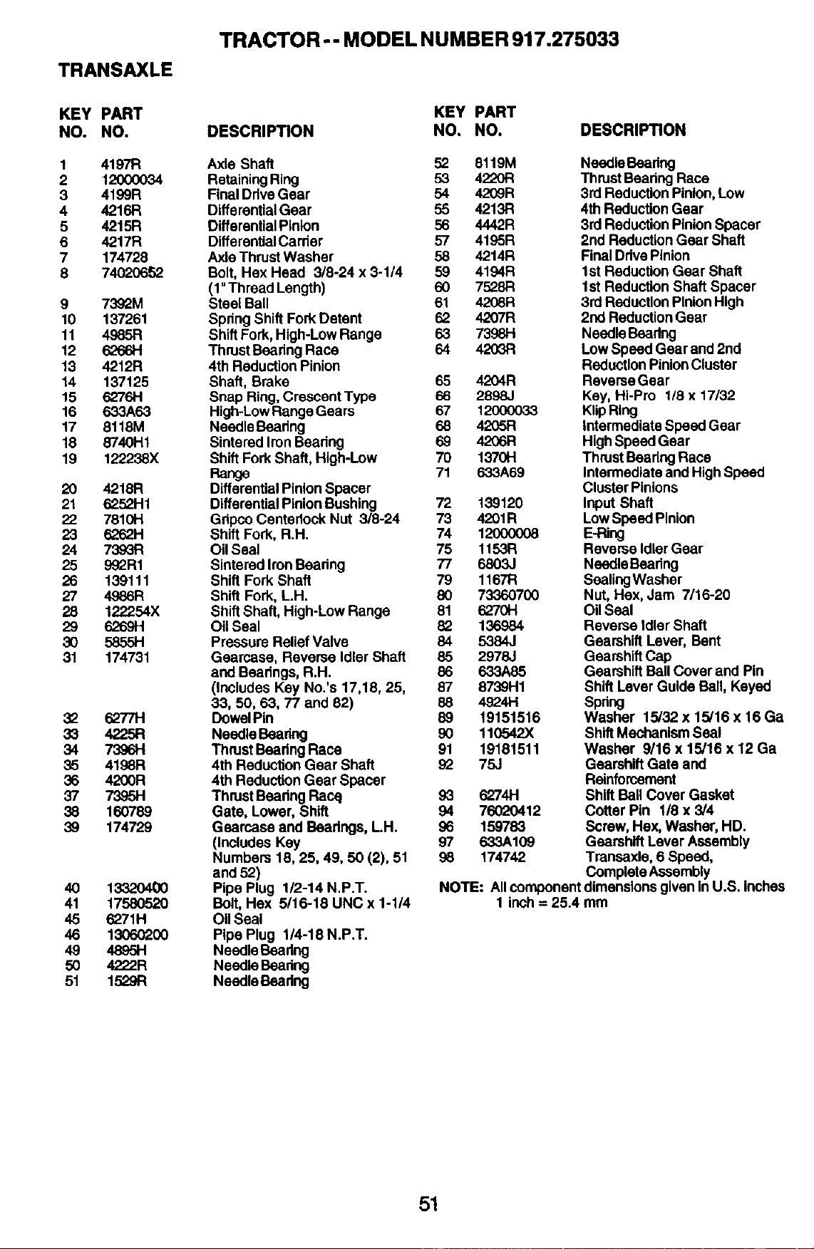
TRANSAXLE
TRACTOR-- MODEL NUMBER 917.275033
KEY PART
NO. NO.
1 4197R
2 12000034
3 4199R
4 42.16R
5 4215R
6 4217R
7 174728
8 74020652
9 7392M
10 137261
11 4985R
12 6266H
13 4212R
14 137125
15 6276H
16 633A63
17 8118M
18 8"/4OH1
19 122238X
20 4218R
21 6252H1
22 7810H
23 6262H
24 7393R
25 99_R1
26 139111
27 4986R
28 122254X
29 6269H
30 5855H
31 174731
32 6277H
33 4225R
34 73961-1
35 4198R
36 4200R
37 7395H
38 160789
39 174729
4O 1332O400
41 1758O52O
45 6271H
46 13060200
49 4995H
5O 4222R
51 1529R
KEY PART
DESCRIPTION NO. NO.
Axle Shaft 52 8119M
RetainingRing 53 4,'220t:1
FinalDdveGear 54 4209R
DifferentialGear 55 4213R
DifferentialPinion 56 4442R
DifferentlalCarrier 57 4195R
AxleThrustWasher 58 4214R
Belt, HexHead 3/8-24 x 3-1/4 59 4194R
(1"ThreadLength) 60 7528R
SteelBall 61 4208R
SpnngShiftFork Detent 62 4207R
ShiftFork,High-LowRange 63 73981-1
ThrustBeadngRace 64 4203FI
4thReductionPinion
Shaft, Brake 65 4204R
Snap Ring,CrescentType 66 2898J
High-LowRangeGears 67 12(X)0033
NeedleBeadng 68 4205R
SintaredIronBeadng 69 4206R
ShiftForkShaft,High-Low 70 1370H
Range 71 633A69
DifferentialPinionSpacer
DifferentialPinionBushing 72 139120
GdpcoCentsdockNut 3/8-24 73 4201R
ShiftFork, R.H. 74 12000008
OilSeal 75 t 153R
SintaredIronBeadng 77 6803J
Shift ForkShaft 79 1167R
Shift Fork,L.H. 80 73360700
ShiftShaft,High-LowRange 81 6270H
Oil Seal 82 136984
PressureReliefValve 84 5384J
Gsarcase, ReverseIdlerShaft 85 2978J
and Bsadngs,R.H. 86 633A85
(IncludesKey No.'s 17,18, 25, 87 8739H1
33, 50, 63, 77 and 82) 88 4924H
DowelPin 89 19151516
NeedleBeadng 90 110542X
Thrust BeadngRace 91 19181511
4thReductionGear Shaft 92 75J
4thReductionGear Spacer
ThrustBeadngRacq 93 3274H
Gate, Lower,Shift 94 76020412
Gearcaeeand Bearings,LH. 96 159783
(IncludesKey 97 633A109
Numbers18, 25, 49, 50 (2), 51 98 174742
and 52)
Pipe Plug 1/2-14 N.P.T.
Bolt,Hex 5/16-18 UNC x 1-1/4
OII Seal
Pipe Plug 1/4-18 N.P.T.
NeedleBeadng
NeedleBeadng
NeedleBeadng
DESCRIPTION
NeedleBeadng
ThrustBearingRace
3rdReductionPinion,Low
4thReductionGear
3rdReductionPinionSpacer
2nd ReductionGear Shaft
FinalDdvePinion
1stReductionGear Shaft
1stReductionShaft Spacer
3rdReductionPinionHigh
2nd ReductionGear
NeedleBeadng
LowSpeedGearand2nd
ReductionPinionCluster
RsverseGsar
Key, Hi-Pro 1/8 x 17132
KlipRing
IntermediateSpeedGear
HighSpeedGear
ThrustBearingRace
IntermediateandHighSpeed
ClusterPinions
InputShaft
LowSpeedPinion
E-Ring
ReverseIdlerGear
NeedleBeadng
SealingWasher
Nut, Hex, Jam 7/16-20
OilSeal
ReveresIdlerShaft
GearshiftLever, Bent
GearshiftCap
GearshiftBallCoverand Pin
ShiftLever GuideBall, Keyed
Spdng
Washer 15/32 x 15/16 x 16 Ga
ShiftMechanismSeal
Washer 9/16 x 15/16 x 12 Ga
GearshiftGate and
Reinforcement
ShiftBallCover Gasket
Cotter Pin 118x 3/4
Screw,Hex,Washer,HD.
GearshiftLeverAssembly
Transaxle,6 Speed,
Complete Assembly
NOTE: AllcomponentdimensionsgiveninU.S. inches
1 inch= 25.4 mm
51
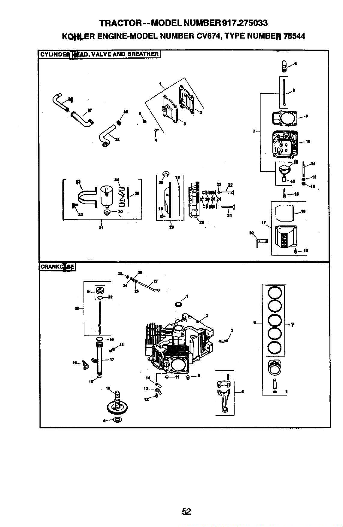
TRACTOR - - MODEL NUMBER 917.275033
KO_II.ER ENGINE-MODELNUMBER CV674,TYPE NUMBER 75544
CYLINDEI_.JkD, VALVE AND BREATHER I
I
I1
_--III
17
$
/
V
v
v
o,_$
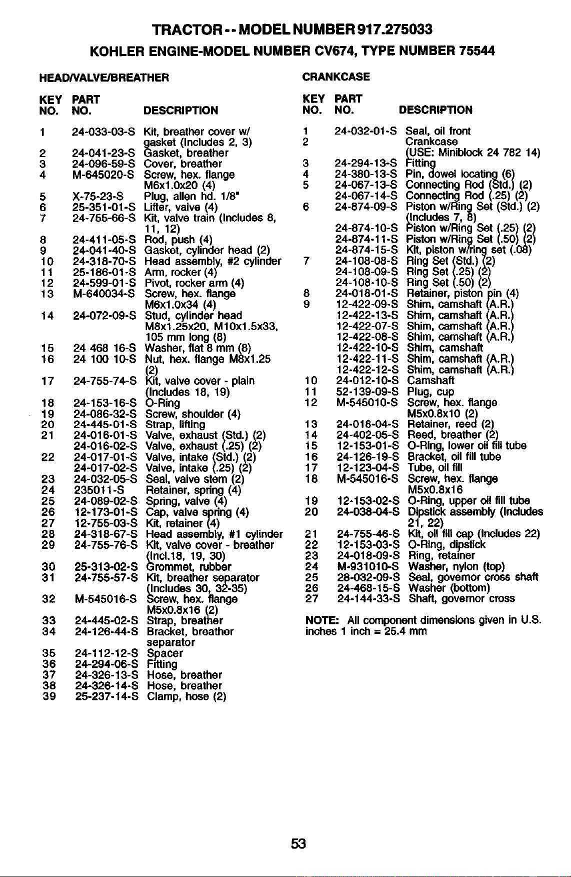
TRACTOR - - MODEL NUMBER 917.275033
KOHLER ENGINE-MODEL NUMBER CV674, TYPE NUMBER 75544
HEADNALVE/BREATHER
CRANKCASE
KEY PART KEY PART
NO. NO. DESCRIP_ON NO. NO. DESCRIPTION
1 24-033-03-S Kit, breather cover w/ 1 24-032-01-S
gasket (Includes 2, 3) 2
2 24-041-23-S Gasket, breather
3 24-096-59-S Cover, breather 3 24-294-13-S
4 M-645020-S Screw, hex. flange 4 24-380-13-S
M6xl.0x20 (4) 5 24-067-13-S
5 X-75-23-S Plug, allen hd. 1/8" 24-067-14-S
6 25-351-01-S Lifter, valve (4) 6 24-874-09-S
7 24-755-66-S Kit, valve train (Includes 8,
11, 12) 24-874-10-S
8 24-411-05-S Rod, push (4) 24-874-11-S
9 24-041-40-S Gasket, cylinder head (2) 24-874-15-S
10 24-318-70-S Head assembly, #2 cylinder 7 24-108-08-S
11 25-186-01-S Arm, rocker (4) 24-108-09-S
12 24-599-01-S Pivot, rocker arm (4) 24-108-10-S
13 M-640034-S Screw, hex. flange 8 24-018-01-S
M6x1.0x34 (4) 9 12-422-09-S
14 24-072-09-S Stud, cylinder head 12-422-13-S
M8x1.25x20, MlOx1.5x33, 12-422-07-S
105 mm long (8) 12-422-08-S
15 24 468 16-S Washer, flat 8 mm (8) 12-422-10-S
16 24 100 10-S Nut, hex. flange M8x1.25 12-422-11-S
(2) 12-422-12-S
17 24-755-74-S Kit, valve cover - plain 10 24-012-10-S
(Includes 18, 19) 11 52-139-09-S
18 24-153-16-S O-RIOg 12 M-545010-S
19 24-086-32-S Screw, shoulder (4)
20 24-445-01-S Strap, lifting 13 24-018-04-S
21 24-016-01-S Valve, exhaust (Std.) (2) 14 24-402-05-S
24-016-02-S Valve, exhaust (.25) (2) 15 12-153-01-S
22 24-017-01-S Valve, intake (Std.) (2) 16 24-126-19-S
24-017-02-S Valve, intake (.25) (2) 17 12-123-04-S
23 24-032-05-S Seal, valve stem (2) 18 M-545016-S
24 235011-S Retainer, spring (4)
25 24-089-02-S Spdng, valve (4) 19 12-153-02-S
26 12-173-01-S Cap, valve spdng (4) 20 24-038-04-S
27 12-755-03-S Kit, retainer (4)
28 24-318-67-S Head assembly, #1 cylinder 21 24-755-46-S
29 24-755-76-S Kit, valve cover - breather 22 12-153-03-S
(Inc1.18, 19, 30) 23 24-018-09-S
30 25-313-02-S Grommet, rubber 24 M-931010-S
31 24-755-57-S Kit, breather separator 25 28-032-09-S
(Includes 30, 32-35) 26 24-468-15-S
32 M-545016-S Screw, hex. flange 27 24-144-33-S
M5xO.8x16 (2)
33 24-445-02-S Strap, breather
34 24-126-44-S Bracket, breather
separator
35 24-112-12-S Spacer
36 24-294-06-S FdUng
37 24-326-13-S Hose, breather
38 24-326-14-S Hose, breather
39 25-237-14-S Clamp, hose (2)
Seal, oil front
Crankcase
_USE: Miniblock 24 782 14)
Fitting
Pin, dowel locating(6)
Connecting Rod (Std.) (2)
Connecting Rod (.25) (2)
Piston w/Ring Set (Std.) (2)
(Includes 7, 8)
Piston wiRing Set (.25) (2)
Piston wiRing Set (.50) (2)
Kit, piston w/ring set (.08)
Ring Set (Std.) (2)
Ring Set (.25) (2)
Ring Set (.50) (2)
Retainer, pistonpin (4)
Shim, camshaft (A.R.)
Shim, camshaft (A.R.)
Shim, camshaft (A.R.)
Shim, camshaft (A.R.)
Shim, camshaft
Shim, camshaft (A.R.)
Shim, camshaft (A.R.)
Camshaft
Plug, cup
Screw, hex. flange
M5x0.8xl0 (2)
Retainer, reed (2)
Reed, breather (2)
O-Ring, lower oil fill tube
Bracket, oil fill tube
Tube, oilfill
Screw, hex. flange
M5x0.8xl 6
O-Ring, upper oil fill tube
Dipstick assembly (Includes
21, 22)
Kit, oil fillcap (Includes 22)
O-Ring, dipstick
Ring, retainer
Washer, nylon (top)
Seal, governor cross shaft
Washer (bottom)
Shaft, governor cross
NOTE: All component dimensions given in U.S.
inches 1 inch = 25.4 mm
53
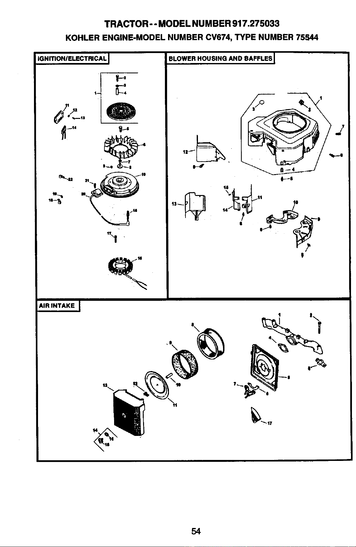
TRACTOR -- MODEL NUMBER 917.275033
KOHLER ENGINE-MODELNUMBER CV674, TYPE NUMBER 75544
IGNITION/ELECTRICAL I
l/tz
AIR INTAKE I
I-,
BLOWER HOUSING AND BAFFLES I
54
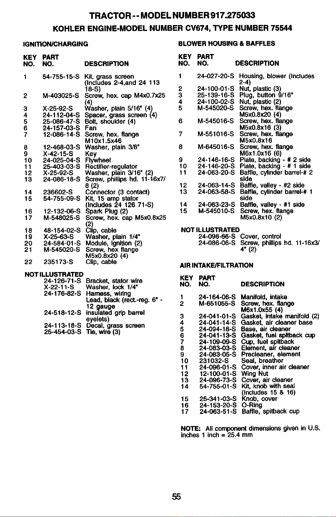
TRACTOR - - MODEL NU MBER 917.275033
KOHLER ENGINE-MODEL NUMBER CV674, TYPE NUMBER 75544
IGNITION/CHARGING
BLOWER HOUSING & BAFFLES
KEY PART KEY PART
NO. NO. DESCRIPTION NO. NO. DESCRIPTION
1 54-755"15"S Kit, grass screen 1 24-027-20-S 2HQusing'-4)blower (Includes
(Includes 2-4,and 24 113
18-S) 2 24-100-01-S Nut, plastic (3)
2 M-403025-S Screw, hex. cap M4x0.7x25 3 25-139-16-S Plug, button 9116"
((4) 4 24-100-02-S Nut, plastic (2)
3 X-25-92-S Washer, plain 5/16" (4) 5 M-545020-S Screw, hex. flange
4 24-1 f2-04-S Spacer, grass screen (4) M5x0.8x20 (4)
5 25-086-47-S Bolt, shoulder (4) 6 M-545016-S Screw, hex. flange
6 24-157-03-S Fan M5x0.8x16 (3)
7 12-086-14-S Screw, hex. flange 7 M-551016-S Screw, hex. flange
M10xl .5x46 M5x0.8x16
8 12-468-03-S Washer, plain 3/8" 8 M-645016-S Screw, hex. flange
9 X-42-15-S Key M6xl.Ox16 (6)
10 24-025-04-S Flywheel 9 24-146-16-S Plate, backing - # 2 side
11 25-403-03-S Rectifier-regulator 10 24-146-20-S Plate, backing - # 1 side
12 X-25-92-S Washer, plain 3/16" (2) 11 24-063-20-S Baffle, cylinder barrel-# 2
13 24-086-18-S Screw, phillips hd. 11-16x7/ side
8 (2) 12 24-063-14-S Baffle, valley - #2 side
14 236602-S Connector (3 contact) 13 24-063-58-S Baffle, cylinder barrel-# 1
15 54-755-09-S Kit, 15 amp stator side
(Includes 24 126 71-S) 14 24-063-23-S Baffle, valley - #1 side
16 12-132-06-S Spark Plug (2) 15 M-545010-S Screw, hex. flange
17 M-548025-S Screw, hex. cap M5x0.8x25 M5x0.8xl0 (2)
(2)
18 48-154-02-S Clip, cable NOT ILLUSTRATED
19 X-25-63-S Washer, plain 1/4" 24-096-66-S Cover, control
20 24-584-01-S Module, ignition (2) 24-086-06-S Screw, phillips hd. 11-16x3/
21 M-545020-S Screw, hex flange 4" (2)
M5xO.8x20 (4)
22 235173-S Clip, cable AIR INTAKE/FILTRATION
NOT ILLUSTRATED
24-126-71-S Bracket, stator wire
X-22-I I-S Washer, lock I/4"
24-176-82-S Harness, wiring
Lead, black (rect.-reg. 6" -
12 gauge
24-518-12-S insulated grip barrel
eyelets)
24-113-18-S Decal, grass screen
25-454-03-S Tie, wire (3)
KEY PART
NO. NO. DESCRIPTION
1
2
24-164-06-S
M-651055-S
3 24-041-01-S
4 24-041-14-S
5 24-094-18-S
6 24-041-13-S
7 24-109-09-S
8 24-083-03-S
9 24-083-05-S
10 231032-S
11 24-096-01-S
12 12-100-01-S
13 24-096-73-S
14 54-755-01 -S
15 25-341-03-S
16 24-153-20-S
17 24-063-51 -S
Manifold, intake
Screw, hex. flange
M6x1.0x55 (4)
Gasket, intake manifold (2)
Gasket, air cleaner base
Base, air cleaner
Gasket, fuel spitback cup
Cup, fuel spitback
Element, air cleaner
Precleaner, element
Seal, breather
Cover, inner air cleaner
Wing Nut
Cover, air cleaner
Kit, knob with seal
KlnCludes15 & 16)
nob, cover
O-Ring
Baffle, spitback cup
NOTE: All component dimensions given in U.S.
inches 1 inch = 25.4 mm
55
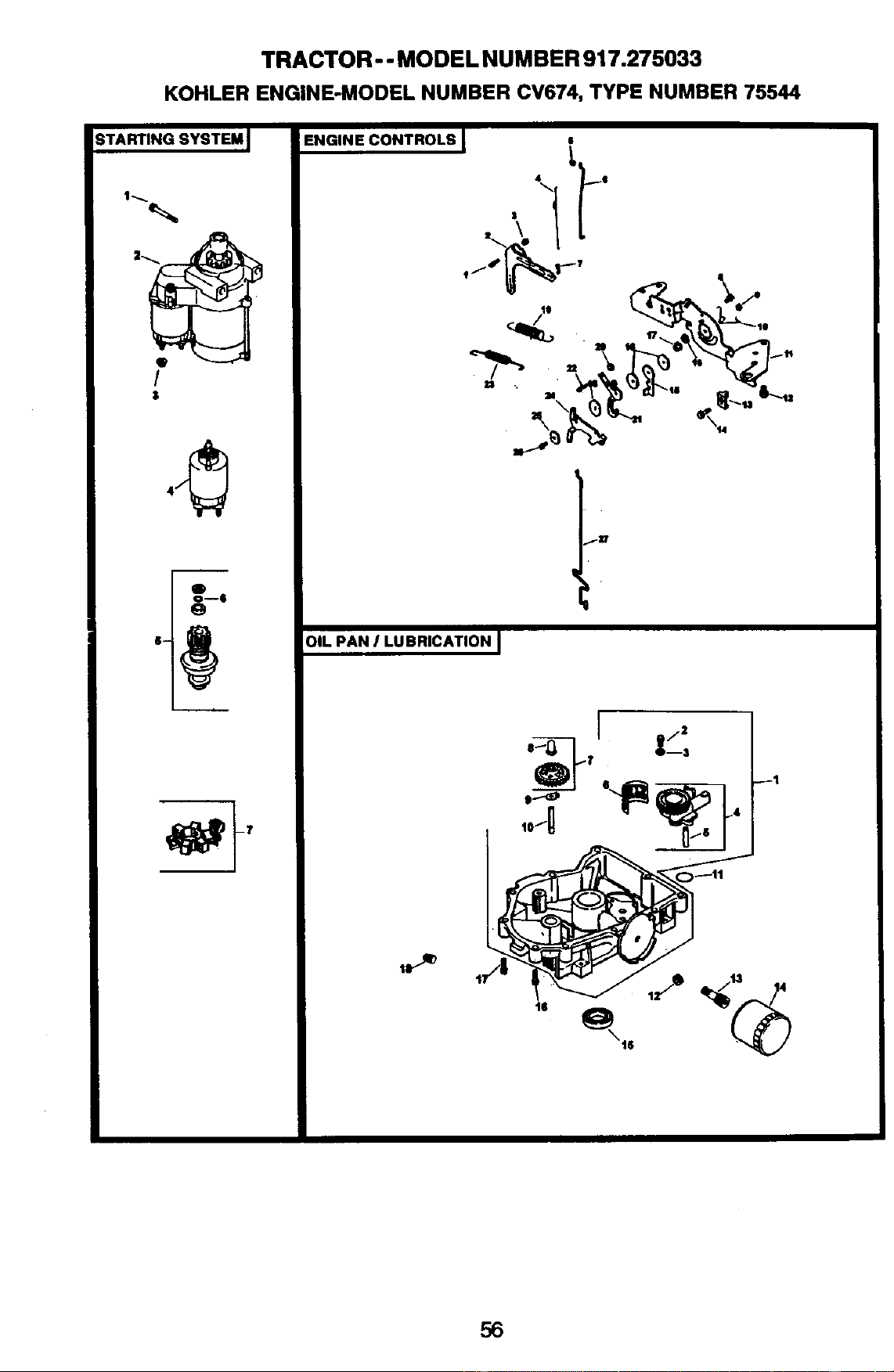
TRACTOR - - MODEL NUMBER 917.275033
KOHLER ENGINE-MODEL NUMBER CV674, TYPE NUMBER 75544
STARTING SYSTEM J
/
$
?---I
ENGINE CONTROLS I •
117
OIL PAN I LUBRICATION J
56
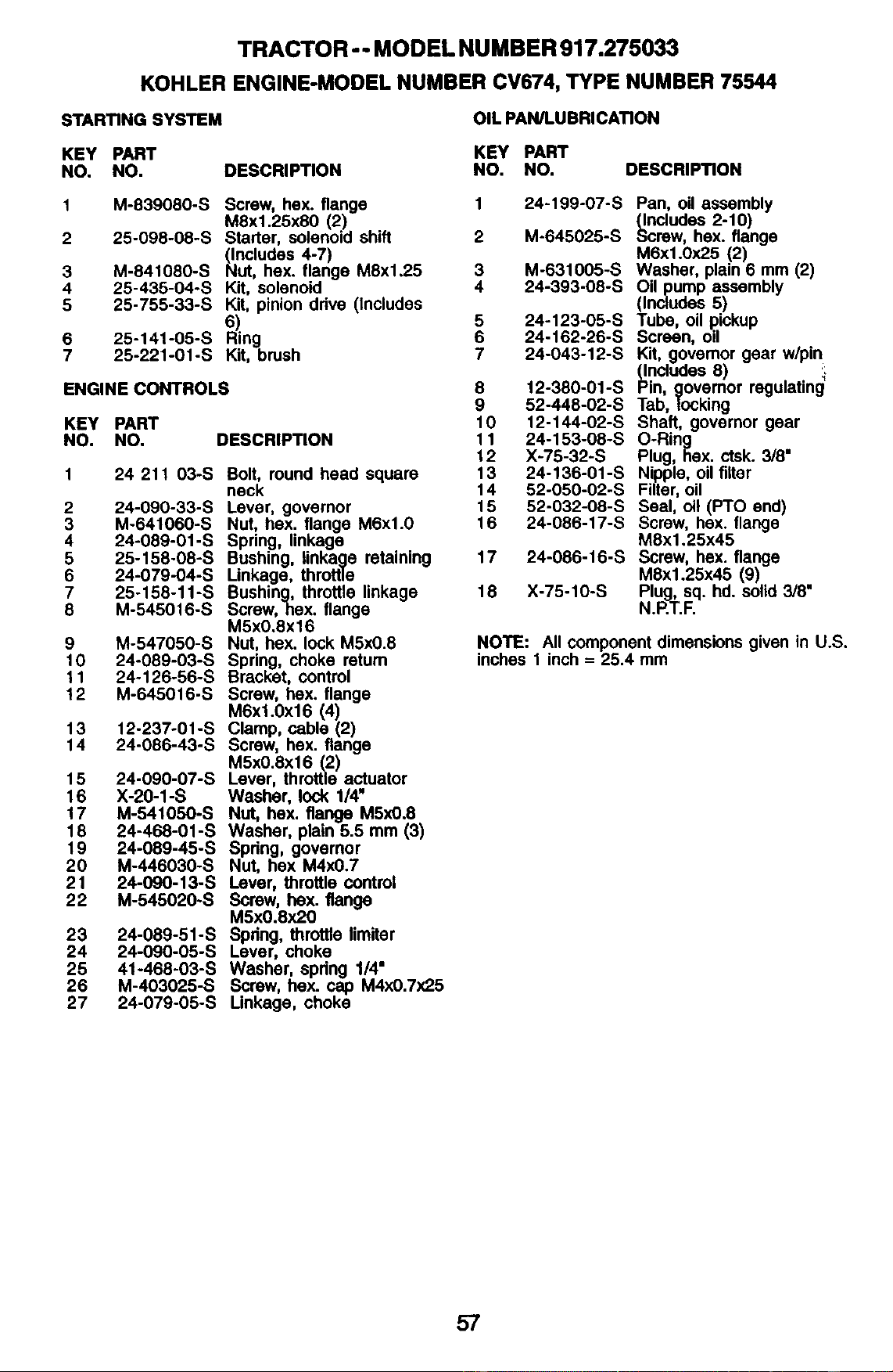
TRACTOR - - MODEL NUMBER 917.275033
KOHLER ENGINE-MODEL NUMBER CV674, TYPE NUMBER 75544
STARTING SYSTEM
OIL PAN/LUBRICATION
KEY PART
NO. NO. DESCRIPTION
KEY PART
NO. NO. DESCRIPTION
1
2
3
4
5
6
7
M-83g080-S
25-098-08-S
M-841080-S
25-435-04-S
25-755-33-S
25-141-05-S
25-221-01 -S
Screw, hex. flange
M8x1.25x80 (2)
Starter, solenoid shift
NlnCludes4-7)
ut, hex. flange M8x1.25
Kit, solenoid
Kit, pinion ddve (Includes
6)
Ring
Kit, brush
ENGINE CONTROLS
KEY PART
NO. NO. DESCRIPTION
2
3
4
5
6
7
8
9
10
11
12
13
14
15
16
17
18
19
20
21
22
23
24
25
26
27
24 211 03-S
24-090-33-S
M-641060-S
24-089-01-S
25-158-08-S
24-079-04-S
25-158-11-S
M-545016-S
M-547050-S
24-089-03-S
24-126-56-S
M-645016-S
12-237-01-S
24-086-43-S
24-090-07-S
X-20-1-S
M-541050-S
24-468-01-S
24-089-45-S
M-446030-S
24-090-13-S
M-545020-S
24-089-51-S
24-090-05-S
41-468-03-S
M-403025-S
24-079-05-S
Bolt, round head square
neck
Lever, governor
Nut, hex. flange M6xl.0
Spring, linkage
Bushing, linkage retaining
Linkage, throttle
Bushing, throttle linkage
Screw,hex. flange
M5xO.8x16
Nut, hex. lock M5x0.8
Spring, choke retum
Bracket, control
Screw, hex. flange
M6xl.0x16 (4)
Clamp, cable (2)
Screw, bex. flange
M5x0.8x16 (2)
Lever, throttle actuator
Washer, lock 1/4"
Nut, hex. flange M5x0.8
Washer, plain 5.5 mm (3)
Spring, govemor
Nut, hex M4x0.7
Lever, throttle control
Screw, hex. flange
M5x0.8x20
Spring, throttle limitar
Lever, choke
Washer, spdng 1/4"
Screw, hex. cap M4xO.7x2.5
Linkage, choke
24-199-07-S
M-645025-S
M-631005-S
24-393-08-S
1
2
3
4
5 24-123-05-S
6 24-162-26-S
7 24-043-12-S
8 12-380-01-S
9 52-448-02-S
10 12-144-02-S
11 24-153-08-S
12 X-75-32-S
13 24-136-01-S
14 52-050-02-S
15 52-032-08-S
16 24-086-17-S
17 24-086-16-S
18 X-75-10-S
Pan, oil assembly
_ncludes 2-10)
crew, hex. flange
M6x1.0x25 (2)
Washer, plain 6 mm (2)
Oilpump _sembly
(Includes
Tube, oil pickup
Screen, oil
Kit, govamor gear w/pin
(Includes 8) :_.
Pin, govemor regulating
Tab, locking
Shaft, governor gear
O-Ring
Plug, hex. ctsk. 3/8"
Nipple, oil filter
Filter,oil
Seal, oil (PTO end)
Screw, hex. flange
M8x1.25x45
Screw, hex. flange
MSxl.25x45 (9)
Plug, sq. hd. solid 3/8"
N.P.T.F.
NOTE: All component dimensions given in U.S.
inches 1 inch = 25.4 mm
57
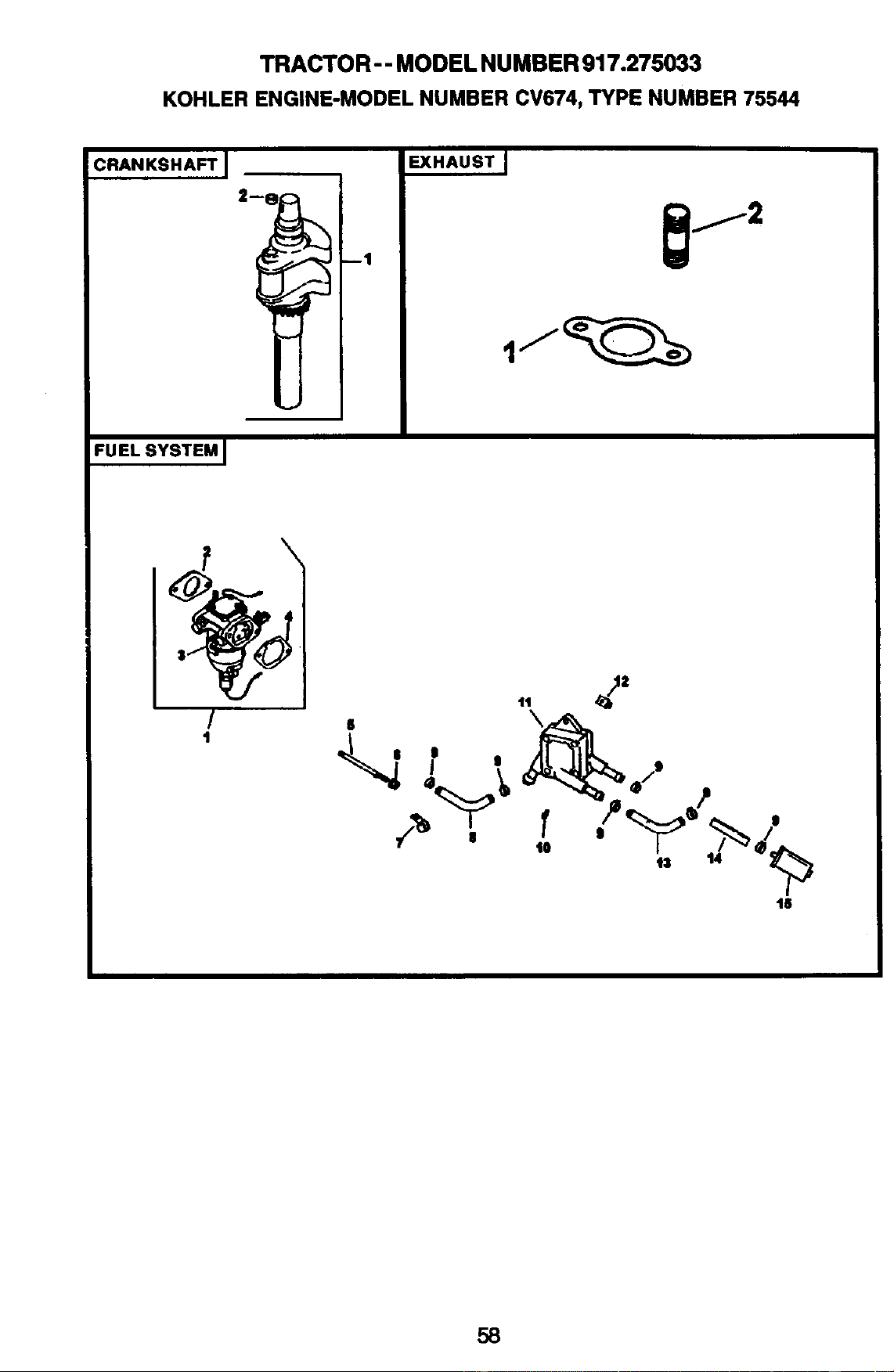
TRACTOR - - MODEL NU MBER 917.275033
KOHLER ENGINE-MODEL NUMBER CV674, TYPE NUMBER 75544
CRANKSHAFT ]
EXHAUST I
FUEL SYSTEM I
/
1
,, 2"
_S $ $ /s
/ , ,-,-,-,-,-,-,-,-,-)%/
18
58
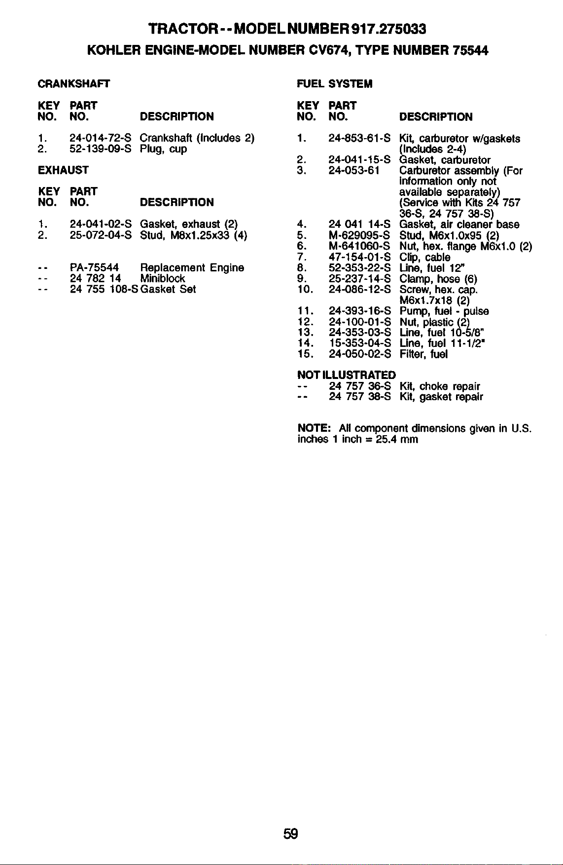
TRACTOR- - MODEL NUMBER 917.275033
KOHLER ENGINE-MODEL NUMBER CV674, TYPE NUMBER 75544
CRANKSHAFT
KEY PART
NO. NO. DESCRIPTION
,
2.
24-014-72-S Crankshaft (Includes 2)
52-139-09-S Plug, cup
EXHAUST
KEY PART
NO. NO. DESCRIP_ON
1. 24-041-02-S Gasket, exhaust (2)
2. 25-072-04-S Stud, M8xl.25x33 (4)
-- PA-75544 Replacement Engine
-- 24 782 14 Miniblock
-- 24 755 108-SGasket Set
FUEL SYSTEM
KEY PART
NO. NO.
DESCRIPTION
1. 24-853-61-S
2. 24-041-15-S
3. 24-053-61
4. 24 041 14-S
5. M-629095-S
6. M-641060-S
7. 47-154-01-S
8. 52-353-22-S
9. 25-237-14-S
10. 24-086-12-S
11. 24-393-16-S
12. 24-100-01-S
13. 24-353-03-S
14, 15-353-04-S
15. 24-050-02-S
Kit, carburetor w/gaskets
_ncludes 2-4)
asker, cadouretor
Carburetor assembly (For
information only not
available separatety)
(Sen/ice with Kits 24 757
36-S, 24 757 38-S)
Gasket, air cleaner base
Stud, M6xl.0x95 (2)
Nut, hex. flange M6xl.0 (2)
Clip, cable
Line, fuel 12"
Clamp, hose (6)
Screw, hex. cap.
M6xl.Txf8 (2)
Pump, fuel - pulse
Nut, plastic (2)
Line, fuel 10-5/8"
Line, fuel 11-1/2"
Filter, fuel
NOT ILLUSTRATEO
-- 24 757 36-S Kit, choke repair
-- 24 757 38-S Kit, gasket repair
NOTE: All component dimensions given in U.S.
inches 1 inch = 25,4 mm
59

60

61

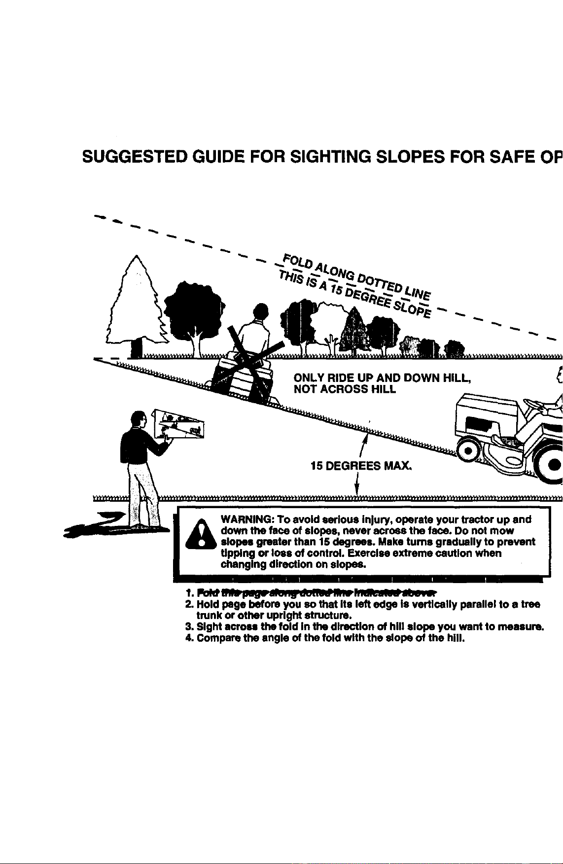
SUGGESTED GUIDE FOR SIGHTING SLOPES FOR SAFE OPERATION
1_ lopss greater than 1S degrees. Make turns gradually to prevent
changing direction on slopes.
1. FOld;;_l.,,-_r--;-,-,_,;--;-.-,:7--- :..-2-.-;-.-; -_.---
2. Hold page before you so that Its left edge Is vcrtlcally parallel to a tree
trunk or other upright structure,
3, Sight across the fold In the direction of hill slope you want to measure,
4. Compare the angle of the fold with the slope of the hill.

Get it fixed, at your home or ours!
ForrepairofmajorbrandappliancesInyourownhome...
nomatterwhomadeit,nomatterwhosold_
1-800-4-MY-HOME_ /_j_n_dayornight
(1-e00-_S_S3) (u.sAandCanada)
WE
wm
Forrepairofcany-inproductslikevacuums,lawnequipment,and
electronics,callforthenearestSears Partsand RepeJrCenter.
1-800-488-1222 AnyUn_dayorrtJt(U.SAody)
wJ
Forthere_ parts,accessod_andowner'smanuals
thatyouneedto(:k:Pit-yourself,callSeers PallSDh'f_b_'SMI
1-800-366-PART 6 a.m,- 11 p.m., 7daysaweek
(1-eoo-3se-7278) (u.sAordy)
wvw_
Topumhaseorinquireabouta Seam Ser_ Agreement
orSearsMainterenceAgmemert
1-800-827-6655 (usa) 1-800-361-6665 (Canada)
7 a.m.- 5 p.m.,CST, Mon.- SaL 9 a.m.-8 p.m.EST, M - F,4 p.m. SaL
Parepedlrse_dode_0wc_n a
dom_ y pam ordenarpleza_
1.888.SU-FlOG/U_su
(1_es-7e4-s427)
AuCanadapoursewi_enfn_l_
1.e(XH.E-FOYER Mc
(1-S00_53_S_
www.sesm.c8
©,_ars, _ ai'd Co.
® RegisteredTrademark/ TMTrademark/ saServiceMarkof Seam, Roebuckand Co.
® Mama Registrada/ nAMama de Fdbdca/ saMama de Serviciode Seem, RoebuckandCo.
ac Marque de commerce/ uoMarqued6pea6ede Seam,Roebuckand Co.
182935 2.11.02 TR Printed in U.S.A.