Loading ...
© 2019 AAMP Global. All rights reserved. PAC is a Power Brand of AAMP Global.
PAC-audio.com
Pacific Accessory Corporation
Page 2
Rev: V3
Date:062419
Advanced Amplier Interface
for Select Toyota Applications
AP4-TY13
Installation
1. To gain access to the amplier, reposition the left front seat forward
and to the highest position.
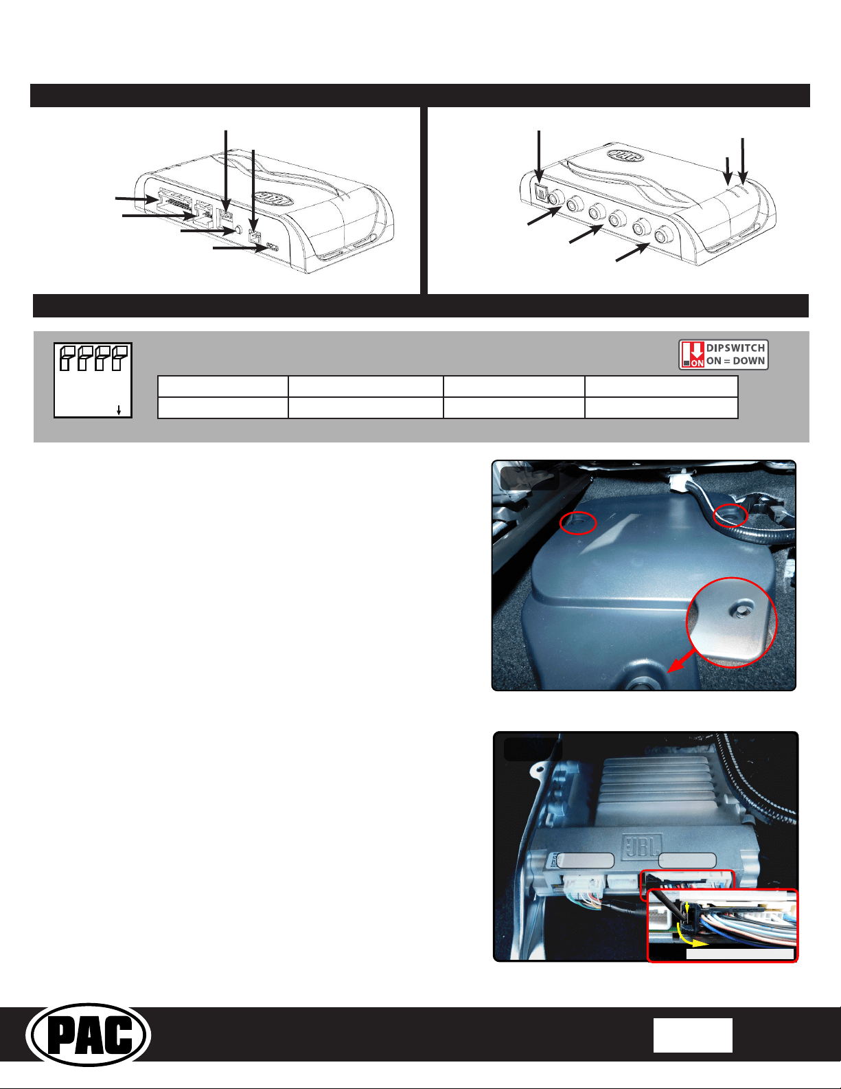
2. Locate the factory amplier cover, remove the 3 push pins that
secure the cover into place, and remove the cover to gain access to
the amplier (Fig. 1).
3. Disconnect the 30-pin harness and the 24-pin harness from the
amplier. To unplug the 30-pin, you must press the inner release tab
and pull the connector's outer release tab at the same time (Fig. 2).
4. Connect the AmpPRO harnesses to the vehicle harnesses.
5. Connect the AmpPRO harnesses to the factory amplier.
6. Set any feature DIP switches that apply to your install.
a. DIP switch 1 is used for two channel mode. In this mode, both
the TOSLINK and front RCA outputs (1 and 2) become non-
fading outputs.
b. Set DIP switch 2 on (down) to lower the RCA output voltage to
4v. Leave DIP switch 2 off (up) to keep the RCA output voltage at
5v. See troubleshooting section on page 6 for more details.
c. Set DIP switch 3 on (down) only if the output of the AP4 is too
low. Doing this will give you a +8 dB boost on the INPUT of the
module.
d. DIP switch 4 is not used and should remain off (up).
6. If you are using the APA-TOS1 (sold separately) refer to the
instructions included with that product for its installation.
7. Connect the AmpPRO harness to the module.
8. Connect the level control knob to the module and install in an
accessible location.
9. Connect the signal cables and remote input from the aftermarket
amplier.
10. Initially, if the beep through the AP4-TY13 does not match the
on / off selection through the radio, cycle the beep to the opposite
setting and back, then test again.
11. See the Tech Brief "AP4-TY SOS Retention" at PAC-audio.com
for detailed instructions for retaining SOS. The Yellow / Black
connections are not necessary when using the AP4-TY13.
DIP
1 2 3 4
ON
Two Channel Mode 5v / 4v Preout Troubleshooting Not Used
1 2 3 4
Set DIP switches to the ON position to activate the corresponding features.
Set DIP switches to the OFF position for any features that are not desired.
Module Layout
LED 1
Interface Connector 1
Expansion Port
TOSLINK Output
(APA-TOS1 sold separately)
Programming Button
Feature Select
DIP switches
Front Output
Ch. 1(L) and 2(R)
Non-Fading Level Control
Knob Connection
USB Connection
Rear Output
Ch. 3(L) and 4(R)
Non-Fading Output
Ch. 5(L) and 6(R)
LED 2
Fig. 1
Fig. 2
24 - Pin 30 - Pin
Press Inner Release Tab
Pull Outer Release Tab
Loading ...
Loading ...
Loading ...