Loading ...
13
AIR CONDITIONING WITH INSTALLATION
• Fit the air exhaust hose (B2) in the relevant housing located
on the rear side of the appliance (g. 1).
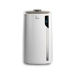
• Drill a hole 150 mm in an outside wall or through a window
panel. Respect the distances, dimensions and heigh of the
hole given in gure 8.
ø 150mm
in the
window
panel
in the wooden
kickboard of a
French window
in the wall: you are
recommended to in-
sulate the section of
wall using suitable
insulation.
• Fit the wall ange (B1) into the hole.
• Fit the air exahaust hose (B2) into the wall ange (B1) (Fig.
9)
• When the hose (B2) is not connected, the drilled hole can
be closed with the ange cap (B1).
Please note: As special tools are required for installation, we
suggest you have the appliance installed by specialized person-
nel.
• When installing the air conditioner, you should leave a door
slightly open little as 1 cm to guarantee correct ventilation
and room pressure.
• Keep the air hose as short and free of curves as possible to
avoid constrictions.
OPERATING FROM THE CONTROL PANEL
C1C2
C4
C11
C13
C19
C20
C9
C7
C5
C6
C3
C16
C14
C12
C10
C15
C17
C8
C18
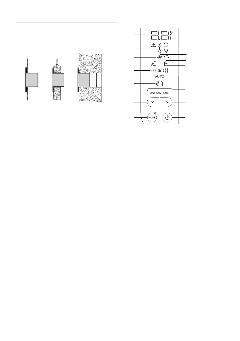
DESCRIPTION OF THE CONTROL PANEL (C)
C1 ON/STAND-BY (on/o) key
C2 Function selection key MODE (air conditioning, dehumidi-
fying, fan, ON-OFF Wi-Fi - reset WLAN settings)
C3 Decrease key
C4 Increase key
C5 Temperature indicator
C6 Timer indicator
C7 Timer symbol
C8 Air conditioning symbol
C9 Dehumidifying symbol
C10 Fan symbol
C11 ECO REAL FEEL indicator
C12 SILENT symbol
C13 Auto indicator
C14 Air ow indicators
C15 Alarm symbol
C16 ECO REAL FEEL symbol
C17 Set temperature values, programmed on/o time
C18 App Indicator
C19 App timer/calendar
C20 Wi-Fi symbol
Loading ...
Loading ...
Loading ...