Range Hood
OWNER'S MANUAL
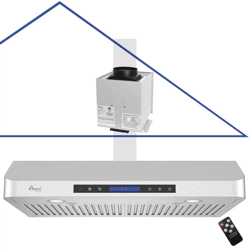
RH-SP Split Under Cabinet Series
Test Run
Before
Installation
Ver. RH-SP-2020A
with
6" or 8" Round Adaptor*
with
3-1/4" x 10" Rectangular Adaptor*
*Depending on the model that you purchased, an appropriate adaptor is included.
*Individual adaptor is available for purchase separately.
*The Adaptor is pre-assembled upside-down on the hood body to save packaging space,
please remove the screws and flip the Adaptor over for the correct assembling position.
HOW TO TEST RUN
Steps To Test Run Before Installation
IMPORTANT!
Wear gloves to protect against sharp edges.
Please follow these instructions to
TEST THE RANGE HOOD
BEFORE INSTALLATION
for any defect or shipping damage:
1. Remove the range hood and accessories from the
package carefully.
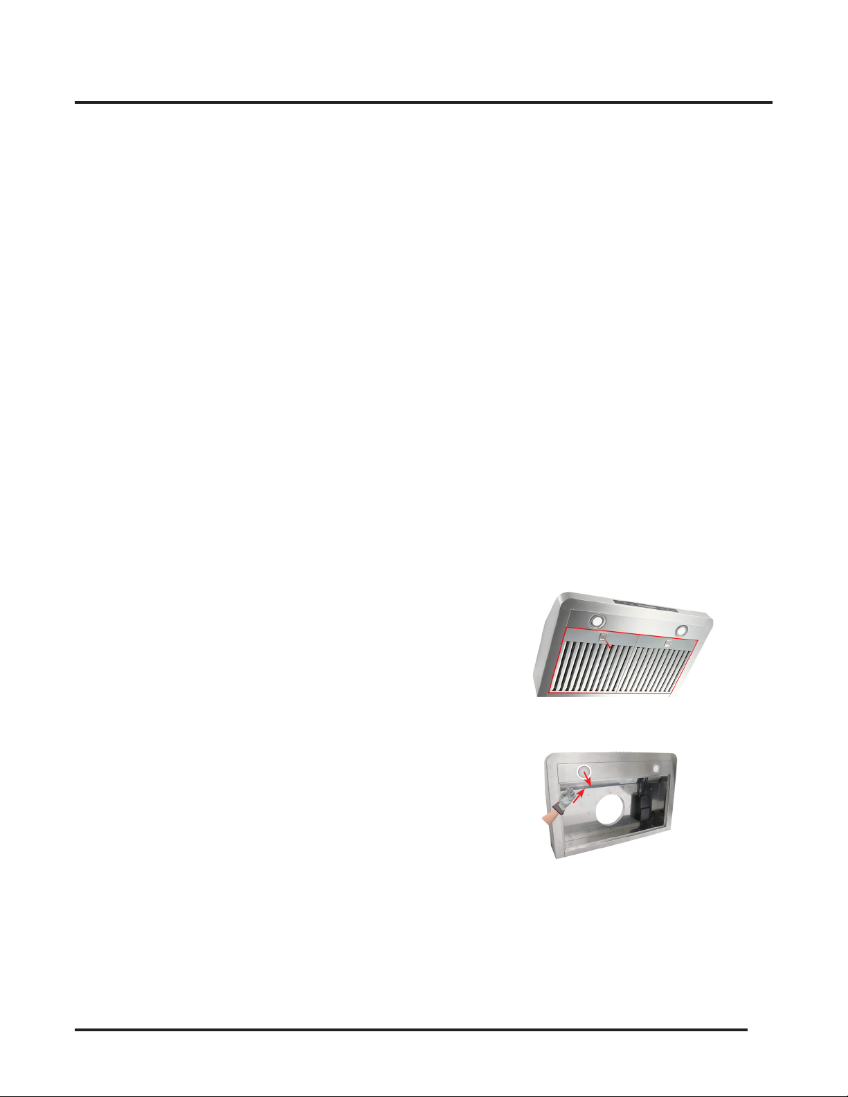
2. Place the range hood on a flat stable surface,
remove the baffle filter and check for any dents or
damages on the range hood body.
3. Remove the loosen parts if there's any.
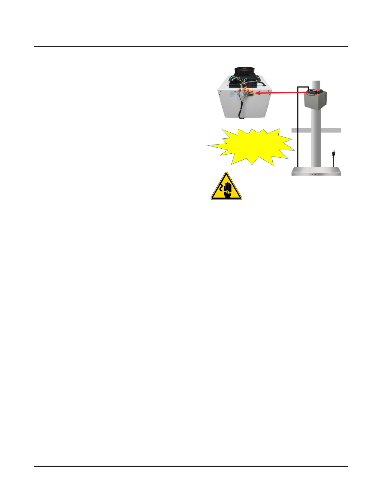
4. Match the wires color and connect the wires as
instructed in the Wiring Diagram on the right
to
connect the Blower Unit to the Hood Unit.
5. Plug the range hood into a 120V AC power source.
Press the power button once and then any of the
speed buttons to turn it on.
6. Check each speed variation and pay attention to
the noise level to make sure there isn't any unusual
noise besides it coming from the wind blowing.
Press the Light Button to check the lights.
7. Verify all functions, as instructed in Page 10, are
working properly.
8. Refer to Range Hood Troubleshooting in Page 12 for
general issues and solutions.
Note
Please don't suspect that a range hood without protective
films is not a new product.
• The protective films on the body was removed to
complete the brush finished polishment on the
surface.
The Baffle Filters might be covered by protective films that
can be removed with the following steps:
• Soak the Baffle Filters into hot waters or use
heated air from a hair dryer to soften the films.
• Peel off the films from the corner.
Wiring Diagram
Important
• This Wiring Diagram is for connecting the wires from
RH-IT Hood Unit to an
Awoco Interior Blower Unit
(Model: RH-SP##-BLW) ONLY.
• If you have an
Awoco Exterior Blower Unit, or any
Blower Unit from other Brands
:
• DO NOT
CONNECT
the wires as shown in this
Wiring Diagram. Any damage from false wiring is
not covered by the warranty.
• Refer to your Blower Unit's USER MANUAL
for
how to properly connect the wires.
Ceiling
Duct
Power
Cord
(120V)
To
Roof Vent
Attic
Kitchen
Hood Unit
Electrical
Hazzard
• DO NOT plug in the Power Cord if these 5 wires are not
connected to the Blower Unit !
• Exposed unconnected wires will cause personal injury
and electrical damage to the motor that is not covered
by the warranty.
Warning
5-Wire Cable
from Blower Unit
5-Wire Cable
from Hood Unit
Simply MATCH THE COLORS
of the Wires and connect
them using twist-on
wire nut connectors
Blower Unit
(Model:
RH-SP##-BLW)
Speed
Control
Cord
(5-Wire Cable)
(Provide Power to
the Blower Unit)
3
Important Safety Instructions 4
Installation Preparations 5
Venting Requirements 5
Venting System Setup 5
Electrical Requirement 6
Installation 7
Installing the Hood Unit 7
Installing the Blower Unit 8
Electrical Connection 8
Installing the Baffle Filters 8
Completing the Installation 8
Range Hood Use 10
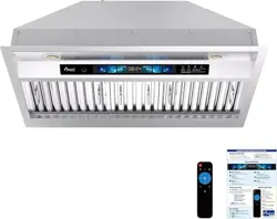
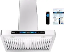
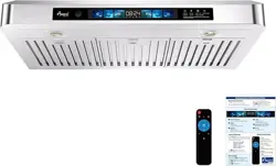
Range Hood Control Panel 10
Range Hood Care 11
Clean the Exterior Surfaces 11
Clean or Replace the Baffle Filters 11
Replace the LED Lamps 11
Range Hood Troubleshooting 12
Warranty 13
Table of Contents
Power Cord
(120V)
Speed Control Cord
(5-Wire Cable)
(Provide Power to the Blower Unit)
Blower Unit
(Model: RH-SP##-BLW)
Hood Unit
Wire Colors and Speeds
Speed Control Cord
Wire Color
Speed
Black
Neutral
White
Speed Quiet (Q)
Orange
Speed Low (L)
Green
Speed Medium (M)
Red
Speed High (H)
Important
• This Diagram is for connecting the wires from RH-IT Hood Unit to an
Awoco Interior Blower Unit (Model: RH-SP##-BLW) ONLY.
• If you have an
Awoco Exterior Blower Unit, or any Blower Unit from other Brands
:
• DO NOT
CONNECT
the wires as shown in this Wiring Diagram. Any damage from false wiring is not covered by the warranty.
• Refer to your Blower Unit's USER MANUAL
for how to properly connect the wires.
Match the wire colors

4
IMPORTANT SAFETY INSTRUCTIONS
TO REDUCE THE RISK OF FIRE, ELECTRIC SHOCK OR
PERSONAL INJURY, PLEASE READ THE FOLLOWING
CAREFULLY BEFORE ATTEMPTING TO ASSEMBLE,
INSTALL, OPERATE OR MAINTAIN THE RANGE HOOD:
• Always disconnect, lock and tag the power source
before installing or servicing the range hood. Failure
to do so may result in fire, shock or serious injury.
• Installation and eletrical wiring must be done
by qualified technician(s) in accordance with all
applicable codes and standards, including fire-rated
construction.
• When cutting or drilling into walls or ceilings, please
be careful not to damage any eletrical wirings and
other hidden utilities.
• Verify and ensure the rated voltage and frequency
of the range hood is in compliance with the nearby
power source.
• Always unplug the range hood from the power
source before cleaning it.
• Use the range hood only as directed in this manual.
Do not use it to vent hazardous or explosive
materials or vapors.
• Clean the baffle filters regularly to prevent it become
blocked or clogged. Good air flow is essential for the
range hood to work propoerly.
• Do not install, repair or replace any parts of the
range hood unless you are instructed to do so by
the manufacturer.
• Do not tamper with or modify the PCB.
• This range hood model requires a duct to vent the
air outside. Do not vent the air into spaces within
walls, ceiliings, attics, crawl spaces or garages.
TO REDUCE THE RISK OF A RANGE TOP GREASE FIRE:
• Never leave surface units unattended at high
settings. Boilovers cause smoking and greasy
spillovers that may ignite. Heat oils slowly on low or
medium settings.
• Always turn the hood ON when cooking at high
heat or when flambeing food (i.e. Crepes Suzette,
Cherries Jubilee, Peppercorn Beef Flambé).
• Clean ventilating fans frequently. Grease should not
be allowed to accumulate on the fan or filter.
• Use proper pan sizes. Always use cookware
appropriate for the size of the surface element.
TO REDUCE THE RISK OF INJURY TO PERSONS IN THE
EVENT OF A RANGE TOP GREASE FIRE:
• SMOTHER FLAMES with a close-fitting lid, cookie
sheet or metal tray, then turn off the burner. BE
CAREFUL TO PREVENT BURNS. If the flames do not
go out immediately, EVACUATE AND CALL THE FIRE
DEPARTMENT.
• NEVER PICK UP A FLAMING PAN - you may be
burned.
• DO NOT USE WATER, including wet dish cloths or
towels - a violent steam explosion may result.
• Use a fire extinguisher ONLY if:
• You have a Class ABC extinguisher, and you
already know how to operate it.
• The fire is small and contained in the area
where it started.
• The fire department is being called.
• You can fight the fire with your back to an exit.
TO REDUCE THE RISK OF PERSONAL INJURY IN THE
EVENT OF A GAS LEAK:
• Extinguish any open flame.
• DO NOT turn on the lights or any type of appliance.
• Open all doors and windows to disperse the gas.
If you still smell the gas, call the gas company, fire
department, or 911 immediately.
Read and Save These Instructions
5
INSTALLATION PREPARATIONS
Please read all instructions carefully before proceeding
further to prevent the risk of fire, electric shock, personal
injury or damage to the range hood. This manual
provides a general insight on the installation and may
not include solutions for all possible issues that may
occur.
In case of this manual destroyed or lost, please visit
https://www.awoco.com and download a digital version.
Installation Overview
1. Unpack the range hood and check for any physical
damage on the body.
2. Test run the range hood and check if all functions
are working properly. Refer to Page 9 for
functionalities.
DO NOT
install the range hood if it's defective. Contact
the seller immediately.
3. If all is fine, install the range hood as instructed in
this manual. Refer to Page 7.
4. Test run the range hood again when the installation
is finished. Refer to Page 11 for troubleshooting.
Possible Tools Needed:
• Marker / Pencil;
• Jig Saw or Reciprocating Saw;
• Screwdrivers or Power Drill;
• Level;
• Measuring Tape;
• Knife:
• Duct / Foil Tape;
• Screws.
2 PEOPLE ARE REQUIRED FOR THE INSTALLATION.
Venting Requirements
DO
• Have the venting system go vertically from the
range hood to the roof if possible.
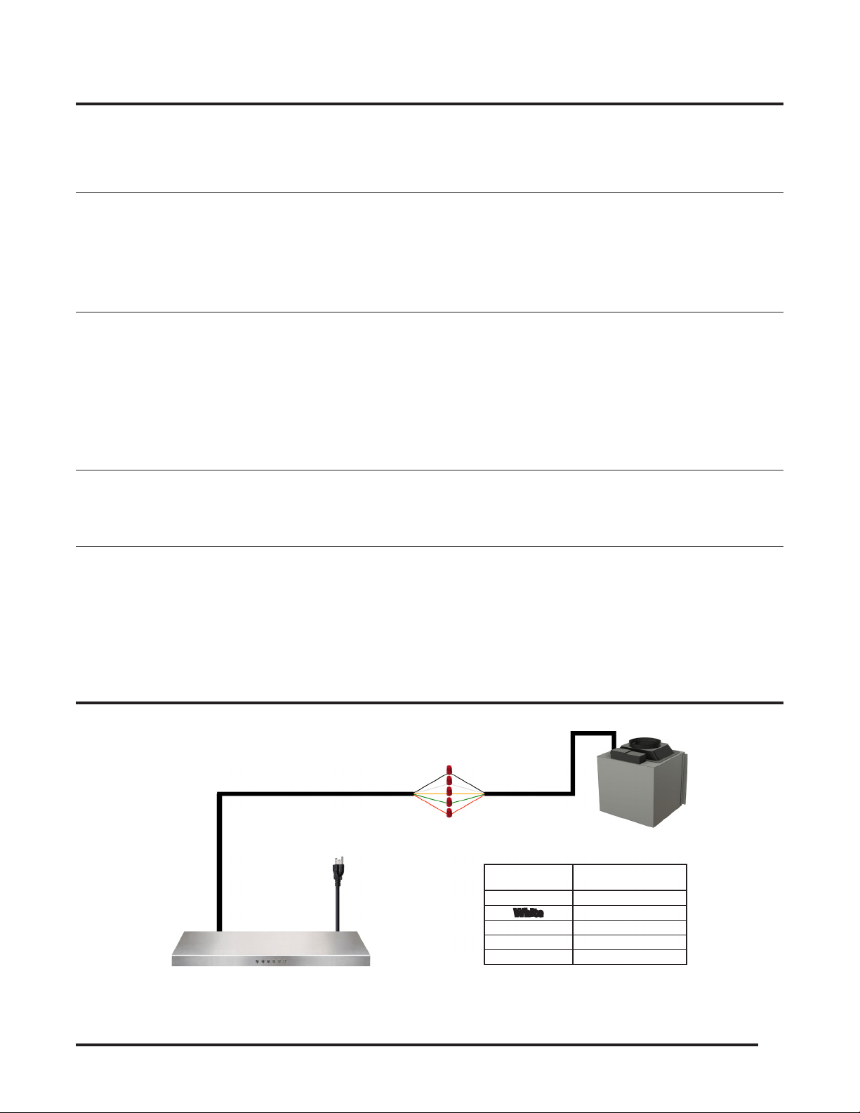
• Have 24"-30" distance between the cooktop and
the range hood. 27" is recommended.
• Use uniformed 6" round duct for 6" Round Adaptor,
or 8" round duct for 8" Round Adaptor, or 3-1/4 x
10” rectangular duct or larger.
• Use metal vent only. Rigid metal vent is
recommended. Semi-rigid aluminum vent is also
acceptable for easy connection.
• Make sure there is a minimum of 24" of straight
vent between the elbows if more than 1 elbow is
used.
• Use minimal numbers of elbows and the
shortest route for the venting system for a better
performance.
• Use silver tap or duct tap to seal all joints in the
venting system.
• Use caulking silicone to seal exterior wall or roof
opening around the cap.
• Always keep the duct clean to ensure proper airflow.
6
INSTALLATION PREPARATIONS
DO NOT
• End the venting system in an enclosed area indoors.
• Use plastic vent.
• Use no more than three 90° elbows.
• Install 2 elbows together.
• Install the range hood outside of the recommended
height.
• Reduce the duct size below the recommended size.
IMPORTANT!
• If long duct run is needed, increase the duct size
from 6" to 7" or 8" to 9".
• If a reducer is needed, use a long reducer instead of
a pancake reducer and install it as far away from the
range hood as possible. Reducing the duct size will
restrict and decrease the speed of the airflow and
hense lower the range hood's performance.
• If transitions or turns are needed, install them as far
away from the range hood as possible and keep the
distance between the 2 as far apart as possible.
• Also refer to the owner's manual of the stove
top for the height clearance requirement and the
recommended mounting height above the range.
Minimum Duct Size:
• Round: 6" minimum for 6" Round Adaptor.
8" minimum for 8" Round Adaptor.
• Rectangular: 3-1/4" x 10" minimum.
IMPORTANT!
Observe all governing codes and ordinances.
It is the customer's responsibility:
• To contact a qualified electrical installer;
• To ensure that the electrical installation is in
compliance with applicable codes and standards.
Electrical Requirements:
• A 120V, 60Hz., AC only, 15A fused electrical circuit is
required.
• Wire sizes and connections must conform with the
power rating of the range hood and all applicable
codes and standards.
• DO NOT have a fuse in the neutral or ground circuit.
• The 3-prong outlet should be grounded. If the
power cord plug is not used, the power cord’s green
wire should be connected to ground. Check with
a qualified electrician if you are not sure that the
range hood is properly grounded.
• DO NOT ground to a gas pipe.
• The range hood must be connected with copper
wire/plug only.
• The range hood should be connected directly to the
fused disconnect box (or circuit breaker) through
flexible armored or non-metallic sheathed copper
cable. ETL listed strain relief must be provided at
each end of the power supply cable.
7
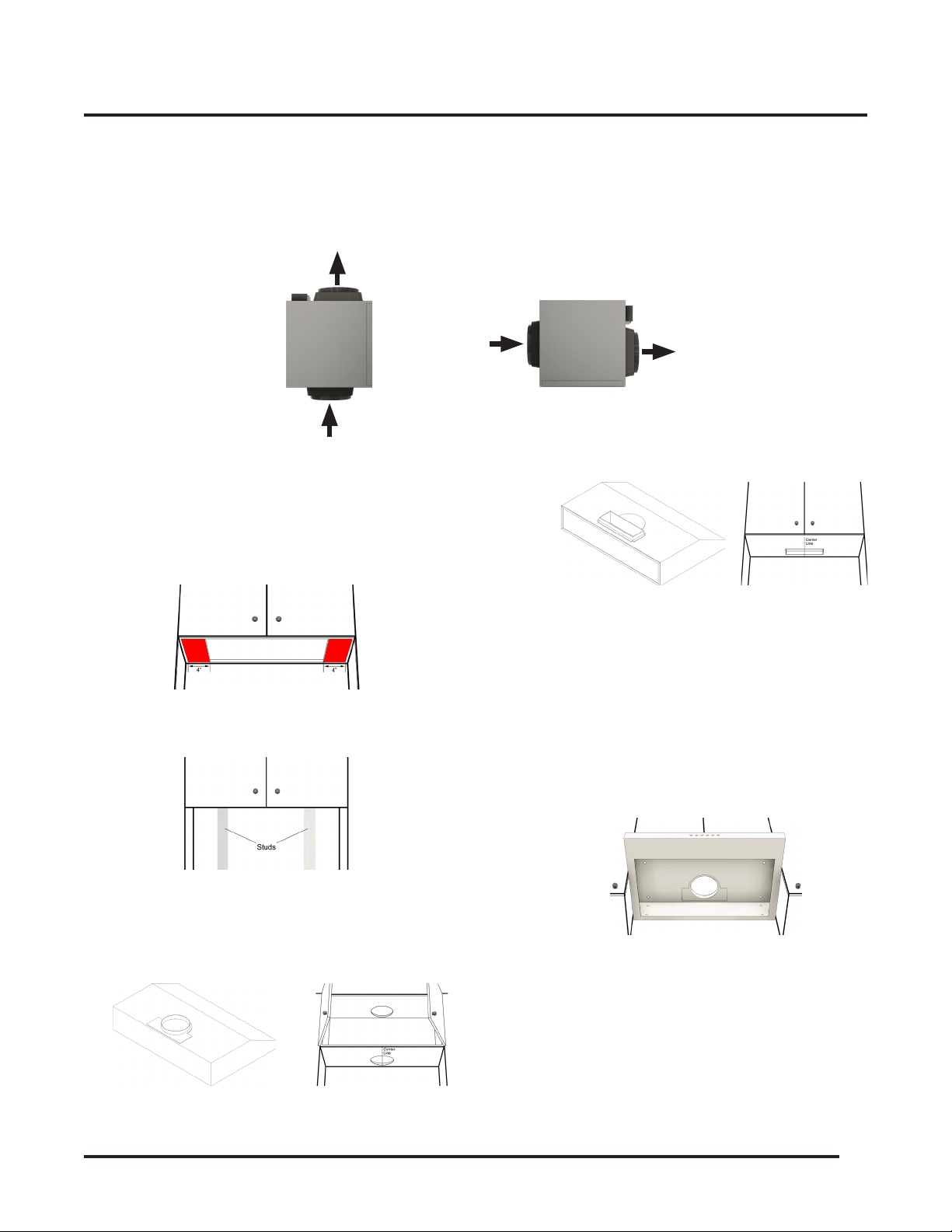
Identify the Vent In and Out Openings on the Blower Unit
• The Blower Unit has Vent In and Vent Out on 2 opposite sides. One side with just a Vent In and the other side with a
Black Speed Control Box and a Vent Out.
INSTALLATION
Connection
Box
Vent out to
the Roof
Vent in from the
Hood Unit
Vent in from the
Hood Unit
Vent out to
the Roof
Blower Unit Installed Vertically Blower Unit Installed Horizontally
Installing the Range Hood
• For installing under the cabinet with recessed
bottom, attach a 4" wide wood filler strip (not
provided) on each side.
• Use a stub finder to locate and mark 2 studs inside
the wall.
• Make 2 cutouts on the top and bottom of the
cabinet that align with the outlet of the top vent
on the hood. The diameter of the cutout should be
slightly larger than the diameter of the duct.
The following steps require 2 or more people:
• Draw the power cord through the bottom
cutout and align the range hood beneath the
cabinet so that the exhaust on the hood and
the cutout are in line.
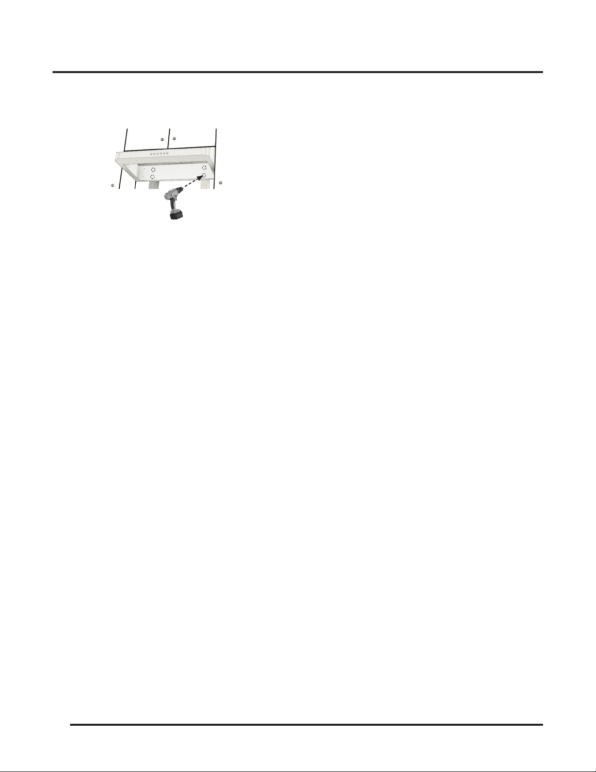
• Raise and screw the top of the hood to the
bottom of the cabinet through the knockout
holes shown below:
• Tighten all screws until the range hood is
securely mounted to the bottom of the cabinet.
Make sure the range hood is securely mounted
before releasing.
• For a more secure installation, install additional
screws into the pre-drilled holes on the
backplate of the range hood to secure it to the
Attach wood ller strips
* For Models with Round Adaptor Only
* For Models with Rectangular Adaptor Only
8
INSTALLATION
studs or lumbers. If the pre-drilled holes don't
align with the studs or lumbers, drill new holes
on the backplate instead.
Connecting the Vent System
• Use 6” or 8" round, or 3-1/4 x 10” rectangular metal
duct (or semi-rigid aluminum duct, follow the local
building codes) to connect the exhaust on the hood
to the duct-work above.
• Use foil tape or duct tape to seal all connections.
Electrical Connection
WARNING: Electrical Shock Hazard. Disconnect power
before servicing.
• In case of a direct connection to the house wiring is
preferred, do the following:
• Disconnect the power.
• Cut off the plug from the power cord.
• Connect the wires from the power cord to the
wires from the house wiring using UL listed
wire connectors.
Installing the Blower Unit
• Install the mounting brackets to the edges of
the Blower Unit with the screws provided.
• Install the Blower Unit onto the lumbers in the
attic.
• Route the Speed Control Cord and Duct to the
Blower Unit. Use duct elbows to make turns
only when it's needed. Cut and remove the
excess length when done routing.
• Connect the duct to the Blower Unit's vent in
adapter routed from the Hood Unit.
• Connect the duct from the Blower Unit's vent
out adapter to the roof or wall vent out.
• Connect the Duct from the roof to the vent
opening next to the Black Connection Box.
• Use foil tape or duct tape to seal all connections.
• Connect the Speed Control Cord from the Hood
Unit to the Connection Box on the Blower Unit.
See Electrical Connection section below for how
to properly connect the wires
.
CAUTION
For safety purpose, please connect a separate
Gound Wire to the Blower Unit Chassis screw.
(
Note, don't connect the Ground wire to Blower
Unit's Green Speed Wire!!!)
Important
• If you have an
Awoco Exterior Blower Unit, or any
Blower Unit from other Brands
:
• DO NOT
CONNECT
the wires as shown in the
Wiring Diagram. Any damage from false wiring is
not covered by the warranty.
• Refer to your Blower Unit's USER MANUAL
for
how to properly connect the wires.
Electrical Connection
• Connecting
the
Blower Unit
to the
Hood Unit
is as
simple as "
Match Colors and Connect
":
Simply pick the wires with the same color from
both ends and secure them with a wire nut
connector
. (Refer to the Wiring Diagram in the Test
Run section for how to connect the wires properly.)
• This range hood comes with a power cord with
a 3-prong plug. Connect the power cord to a
designated grounded standard 110V outlet.
Warning
Before Plugging the Power Cord to the Outlet:
• Make sure all wires are connected properly between
the Hood Unit and the Blower Unit.
• Insolate any spare wires with electrical tape to prevent
them from touching each other which will result in a
short circuit.

9
Electrical Shock Hazard
Disconnect power before servicing
• In case of a direct connection to the house wiring is
preferred, do the following:
• Disconnect the power.
• Cut off the plug from the power cord.
• Connect the wires from the power cord to the
wires from the house wiring using UL listed
wire connectors.
• Store the excess wires in the wiring box.
• Reconnect the power.
Installing the Baffle Filters
• Peel off the protective film from the baffle filters if
there's any:
• Soak the Baffle Filters into hot waters or use
heated air from a hair dryer to soften the films.
• Peel off the films from the corner.
• Align the baffle filters with the Hood Unit and install
them from left to right.
Completing the Installation
Turn power ON in the control panel. Check all lights and
fan operations.
INSTALLATION
10
RANGE HOOD USE
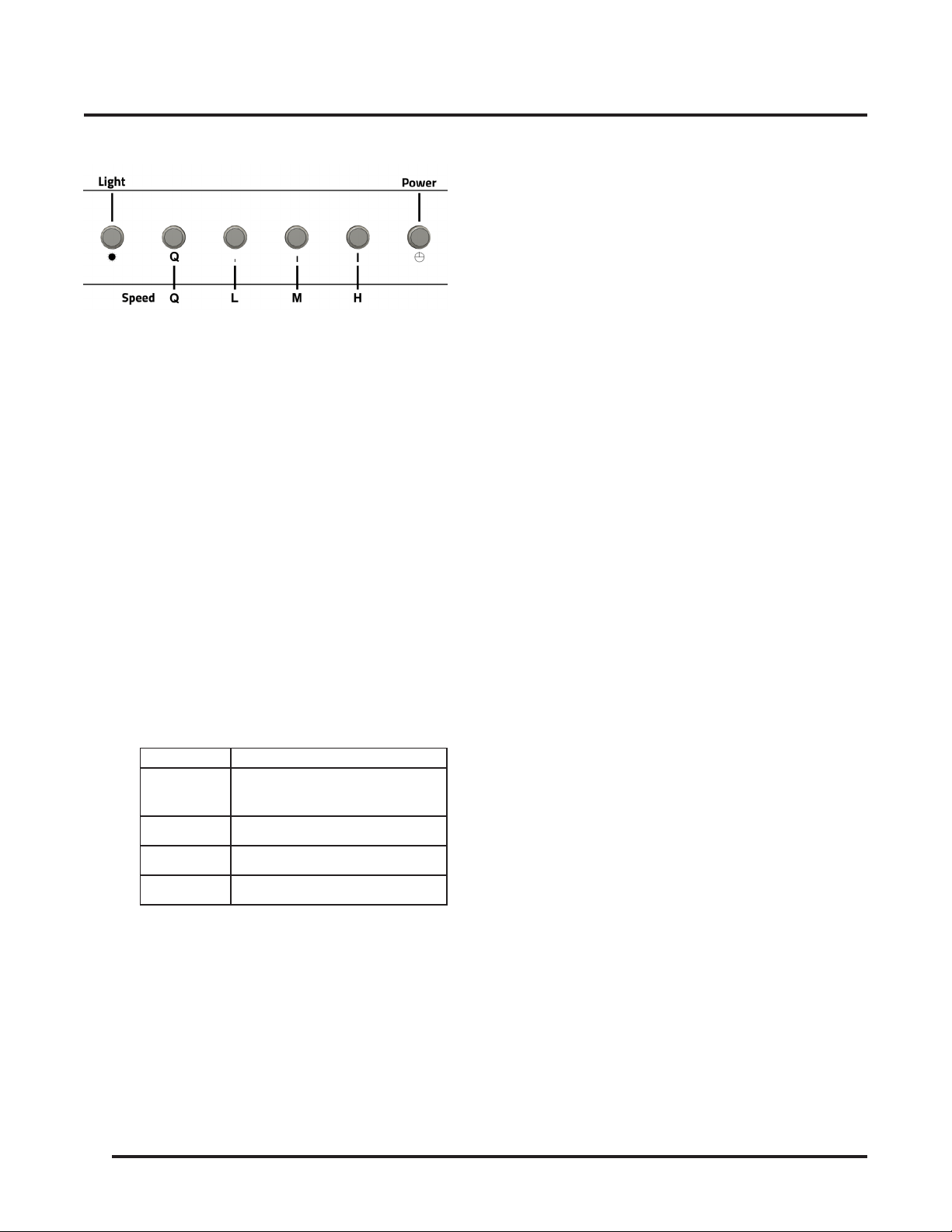
Range Hood Control Panel
• Lamps/Light
• Press the
Light
button once and the lamps will
turn on at maximum brightness.
• When the lamps are on, Press and Hold the
Light
button to reduce the brightness. Release
the
Light
button when the desired brightness is
reached.
• Press the
Light
button again and the lamps will
turn off.
• The lamps can be turned off manually, or
automatically with the
Delayed Auto Shut Off
Function
.
• Speed Control
• There are 4 speed modes you can choose from:
Quiet, Low Speed, Medium Speed and High
Speed.
Button Mode
Q
Quiet - Generate less noise,
perfect for light cookings.
L Low Speed
M Medium Speed
H High Speed
Note
• Pressing any of the speed buttons will turn
on the range hood and set it to the speed the
button designates.
• The last selected speed will be memorized
and resumed the next time the range hood is
turned on by pressing the power button.
• Power
• Pressing the
Power button
can also
turn on
and resume
the Range Hood to
the speed the
last time used
.
• After cooking, press the Power button
once
will activate the
Delayed Auto Shutoff
function
.
• Quickly press the Power button twice
will
shut off
the range hood
immediately
.
3-Minute Delayed Auto Shut Off Function
• When the
range hood is running
at any
speed,
press the Power button once
will
activate the Delayed Auto Shut Off function
.
The countdown timer will start and the range
hood will be shut off automatically in 3
minutes.
• While the Delayed Auto Shut Off function is
activated, press the Power button again and
the range hood will be shut off immediately.
WARNING
Read all instrutions and warnings in the Range Hood
User Manual before using the hood.
• DO NOT use the hood when there are no
safety grills and filters.
• NEVER dispose cigarette ashes, ignitable
substances, or any foreign objects into
blowers.
• NEVER leave the cooking appliances
unattended. When frying, the oil in the pan
can easily overheat and catch on fire. The
risk of self-combustion is higher when the
oil has been used several times.
• NEVER cook on “open” flames under the
range hood. Check deep-fryers during use:
Superheated oil may be flammable.
11
RANGE HOOD CARE
Cleaning
WARNING
• To reduce the risk of electrical shock, DO NOT clean
the hood while it's operating.
• Never put your hands into the area housing the fan
when the fan is operating.
Cleaning the Exterior Surfaces
IMPORTANT
To avoid damage to the exterior surfaces:
• DO NOT use corrosive or abrasive detergent.
• DO NOT use steel wool, scoring pad or steel
brushes. Use a paper towel or soft cloth or
nonabrasive sponge instead.
• DO NOT use salt solutions, disinfectants, bleaches
or cleaning compound that contains harmful
chemicals.
Cleaning Method
• Noncorrosive or nonabrasive liquid detergent
soap or all-purpose liquid cleanser.
• Wipe the surfaces with a damp paper towel or
soft cloth or nonabrasive sponge.
• Rinse with clean water.
• Wip dry with dry towel or cloth.
Note
• The nonabrasive stainless steel polisher can
be applied when done cleaning to retain the
stainless luster and grain.
• Always follow the instrunction of the polisher.
Cleaning the Stainless Steel Baffle Filters
• Pull the spring release handle and remove the
filter by pulling it down.
• Wash the filter in the top rack of the dishwasher
or with warm soapy solution manually.
• Let the filters dry thoroughly.
• Make sure the spring release handle is toward
the front, align and insert the filter.
• Pull the spring release handle and push the
filter into position.
• Release the handle.
• Repeat the steps for the remaining filters.
Replacing the Filters
• Replace the baffle filters immediately should
they become worn out due to aging or
prolonged usage.
Replacing the LED Lamps
WARNING
Electrical Shock Hazard
Disconnect power before servicing
Wear gloves to protect against sharp edges
• This range hood uses 12V, 3W LED. Contact
Awoco customer service to get the replacement
LED lights.
• Unplug the range hood, or turn off the breaker.
• Remove the Baffle Filter adjacent to the Lamp.
• Reach into the Hood Unit and push the Lamp
out from the inside of the Hood Unit.
• Disconnect the wires.
• Connect the wires to the new Lamp.
• Align and put the new Lamp back into position.
• Press the edge of the new Lamp until it touches
the bottom of the Hood Unit.
• Put the Baffle Filter back into place.
• Plug in the range hood, or turn on the breaker.
• Check if the new Lamp is working properly.
Reach into
the Hood
Push the lamp out
Remove
Baffle
Filters
12
Before Calling for Service
Issue Possible Cause / Solution
The range hood doesn't turn on
• Check if the range hood is plugged in. Make sure that all
power is turned ON, the fuse isn't blown and all electrical
wirings are properly connected.
The range hood turns on but the
LED light doesn't
• Replace the defective LED assembly. Refer to Range Hood
Care section for instructions.
The range hood vibrates when
the blower is on
• Check and tighten the mounting screws to secure the hood
to the cabinet or wall properly.
The blower or fan seems weak
• Check that the duct size used is at least 6” and does not have
sections with smaller sizes between the hood and the Roof/
Wall Cap
. Range hood WILL NOT function efficiently with
insufficient duct size. For example: 7” duct over 6” top vent
and not sealed properly.
• Check if the duct is clogged or the damper (half-circular
flapper) is not installed correctly or opening properly. A tight
mesh on a side wall cap might also cause restriction to the
air flow.
The lights work but the blower is
not spinning at all or is rattling
• The blower might be jammed or scraping the bottom due to
shipping damage.
• Disconnect the power cord, remove the fan grill and the fan
blade, might see the fan blade or/and motor is not in the
proper position (offset from the center). Try to fix/adjust it or
please contact us immediately.
The hood is not venting out
properly
• Make sure the distance between the stove top and the
bottom of the hood is within recommended 24” and 30” in
distance. *Due to different ceiling height configurations, the
recommended height may not be applicable.
• Reduce the number of elbows and length of duct work.
Check if all joints are properly connected, taped and sealed.
• Make sure the power is on high speed for heavy cooking.
RANGE HOOD TROUBLESHOOTING

13
This product is warranted for a limited period of
ONE
YEAR Parts, begins from the date of purchase.
This limited warranty is applied to the original retail
purchaser and valid only for products purchased for
home use in the continental United States of America.
This limited warranty is non-transferable and does not
extend to the subsequent owners of this product.
Any applicable implied warranties, including the
warranty of merchantability, are limited in duration to a
period of express warranty as provided herein beginning
with the date of original purchase at retail and, no
warranties, whether express or implied, shall apply to
this product thereafter.
In the event of the product fail to work properly due to
a defect in manufacturing materials or workmanship
under normal home use, during the warranty period
mentioned above, subject to the conditions and
limitations set forth below, Awoco will, at our options,
either repair or replace any part of our products
proven defective by reason of improper materials or
workmanship:
• Proof of original retail purchase is required to
receive warranty service within the limited warranty
period.
• Repair parts or replacement products will be
provided by Awoco, free of charge, on an exchange
basis, and will be either new or reconditioned.
• The consumer is responsible for all shipping costs.
This Limited Warranty Does Not Cover:
• Consumable parts such as light bulbs, stainless
steel baffle filters.
• The natural wear of finish, and wear due to improper
maintenance, use of corrosive and abrasive cleaning
products, pads, and oven cleaner products.
• Chips, dents or cracks on the product caused by
transportation and handling.
• Damage of product caused by accidents, pests and
vermin, lightning, wind, fire, floods or acts of God.
• Damage of product caused by unauthorized
modification or alteration, or if it is used for other
than the intended purpose, or any water leakage
where the unit was not installed properly.
• Damage of product caused by incorrect electrical
wiring, commercial or inductrial use, or use of any
cleaning products not recommended in this manual.
• Damage of product due to product misuse, abuse,
improper installation, unauthorized repair or
maintenance.
• Any loss of properties or any costs associated with
removing, servicing, installing, or determining the
source of problems with our products.
To Receive Warranty Service:
• Contact the seller or distributor from which you
purchase the product. Please confirm the terms
of your dealer’s or distributor’s policies prior to
contacting. Or contact us directly.
• Provide the product identification information, such
as model number and lot number, and proof of
original purchase.
• Decribe the issue you are experiencing in detail.
Product Support and Additional Information:
If you need assistance using your product or you would
like to start the warranty service:
• Contact us at 1-888-412-3428, between 9 AM and
5 PM, Monday - Friday, Pacific Time.
Or
• Contact us at https://www.awoco.com/contact-us.
WARRANTY

Website: www.awoco.com Customer Support: 1-888-412-3428