Loading ...
Loading ...
Loading ...
Sensi Touch 2 Smart Thermostat | INSTALLATION GUIDE 12
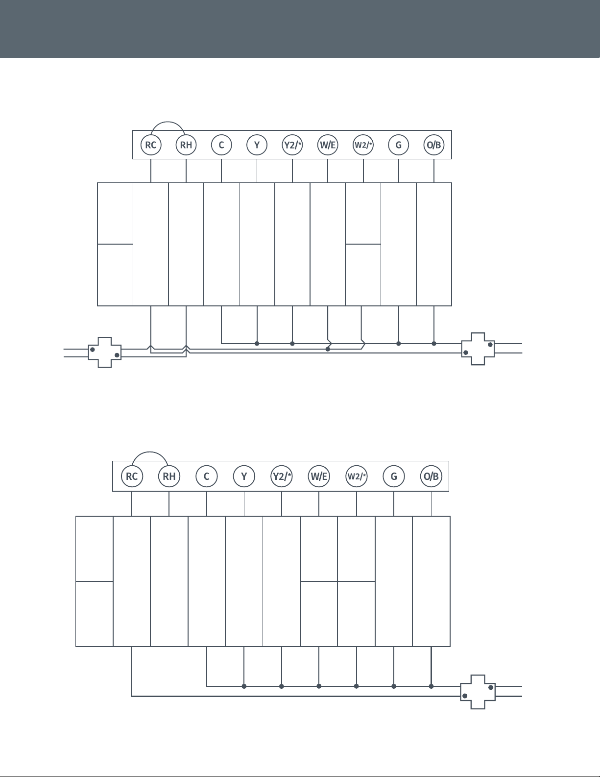
CONVENTIONAL SINGLE-STAGE OR MULTI-STAGE SYSTEMS (NO HEAT PUMP)
System
configuration
Thermostat
†
†
Two transformers systems (separate RC and RH wires), clip internal RC/RH jumper, located on back of thermostat.
HOT
120 VAC
NEUTRAL
HOT
120 VAC
NEUTRAL
NEUTRAL
24 VAC
HOT
NEUTRAL
24 VAC
HOT
Cooling transformerHeating transformer
Dots indicate
phased
relationship
Dots indicate
phased
relationship
Single-stage
(AC1, GA1, EL1)
Power for cooling (24V)
Power for heating (24V)
Common wire (24V)
1st-stage cool
Indoor blower (fan) energized
on call for fan, cool or electric heat
Heat pump changeover, zone panel or
3-wire hot water zone valve connection.
(configurable as O, B or 6
in the installer menu)
1st-stage heat
2nd-stage cool
Multi-stage
(AC2, GA2, EL2)
2nd-stage heat Dehumidifier
HEAT PUMP SYSTEMS
System
configuration
Thermostat
††
†
Internal jumper between RC and RH, located on back of thermostat.
††
Common connection required on heat-only, cool-only or heat pump systems.
HOT
120 VAC
NEUTRAL
NEUTRAL
24 VAC
HOT
Dots indicate
phased
relationship
†
Heat pump
Single-stage
HP1
Power for cooling (24V)
Power for heating (24V)
Common wire (24V)
1st-stage heat and cool compressor
Indoor blower (fan) energized
on call for fan, cool or heat
Heat pump changeover (reversing valve)
connection (configure as O or B
in the installer menu)
2nd-stage heat and
cool compressor
2nd-stage auxiliary/
emergency heat
(3rd-stage heat)
Heat pump
Multi-stage
HP2
1st-stage auxiliary/
emergency heat
(3rd-stage heat)
1st-stage auxiliary/
emergency heat
(2nd-stage heat)
2nd-stage auxiliary/
emergency heat
(4th-stage heat)
NOTES
Loading ...