Loading ...
Loading ...
Loading ...
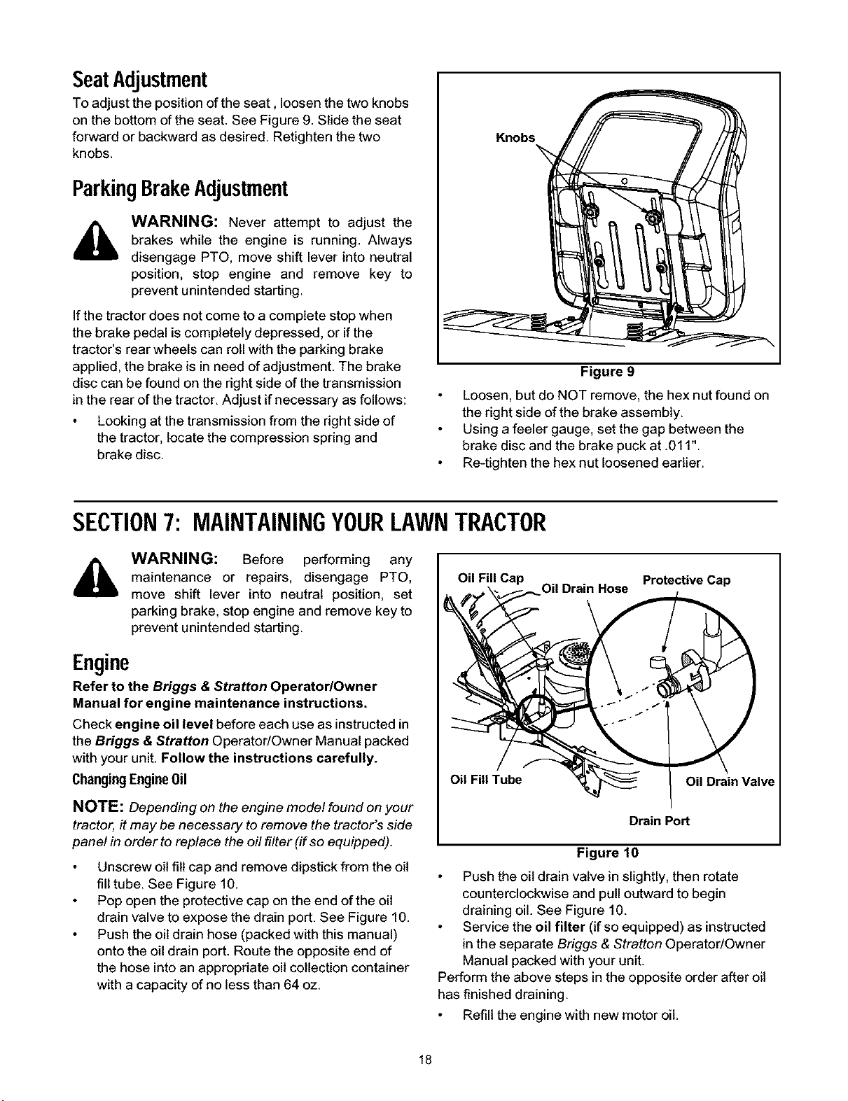
SeatAdjustment
To adjust the position of the seat, loosen the two knobs
on the bottom of the seat. See Figure 9. Slide the seat
forward or backward as desired. Retighten the two
knobs.
ParkingBrakeAdjustment
WARNING: Never attempt to adjust the
brakes while the engine is running. Always
disengage PTO, move shift lever into neutral
position, stop engine and remove key to
prevent unintended starting.
If the tractor does not come to a complete stop when
the brake pedal is completely depressed, or if the
tractor's rear wheels can roll with the parking brake
applied, the brake is in need of adjustment. The brake
disc can be found on the right side of the transmission
in the rear of the tractor. Adjust if necessary as follows:
Looking at the transmission from the right side of
the tractor, locate the compression spring and
brake disc.
Knobs
Figure 9
Loosen, but do NOT remove, the hex nut found on
the right side of the brake assembly.
Using afeeler gauge, set the gap between the
brake disc and the brake puck at .011".
Re-tighten the hex nut loosened earlier.
SECTION7: MAINTAININGYOURLAWNTRACTOR
,_ WARNING: Before performing any I
maintenance or repairs, disengage PTO, Oil FillCap
move shift lever into neutral position, set
parking brake, stop engine and remove key to
prevent unintended starting.
Oil Drain Hose
Protective Cap
Engine
Refer to the Briggs & Stratton Operator/Owner
Manual for engine maintenance instructions.
Check engine oil level before each use as instructedin
the Briggs & Stratton Operator!Owner Manual packed
with yourunit. Follow the instructions carefully.
Changing Engine0il
NOTE: Depending on the engine mode/found on your
tractor, it may be necessary to remove the tractor's side
panel in order to replace the off filter (if so equipped).
Unscrew oil fill cap and remove dipstick from the oil
fill tube. See Figure 10.
Pop open the protective cap on the end of the oil
drain valve to expose the drain port. See Figure 10.
Push the oil drain hose (packed with this manual)
onto the oil drain port. Route the opposite end of
the hose into an appropriate oil collection container
with a capacity of no less than 64 oz.
Oil Fill Tube
Oil Drain Valve
Drain Port
Figure 10
Push the oil drain valve in slightly, then rotate
counterclockwise and pull outward tobegin
draining oil. See Figure 10.
Service the oil filter (ifso equipped) as instructed
in the separate Briggs & Stratton Operator/Owner
Manual packed with your unit.
Perform the above steps in the opposite order after oil
has finished draining.
Refill the engine with new motor oil.
18
Loading ...
Loading ...
Loading ...