8E, q8
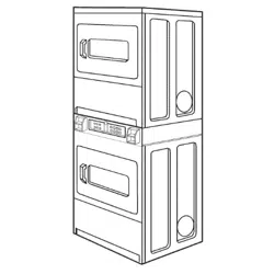
OWNER'S MANUAL
and
INSTALLATION
INSTRUCTIONS
for Electric and Gas
Commercial
Stacked Dryer
SEARS,ROEBUCKANDCO.
HoffmanEstates,IL 60179
www.sears.com
TABLE OF CONTENTS
Dryer Safety ............................................................ 2
Installation Instructions ......................................... 3
Electrical requirements ........................................ 4
Gas requirements .............................................. 10
Exhaust requirements ........................................ 12
Recessed area/closet installation ...................... 14
Other Installation ................................................ 15
Operating the dryer .............................................. 18
Troubleshooting .................................................... 19
Service and Assistance ....................................... 24
For Sears warranty information or to contact a Sears Service
Center, call 1-800-4-MY HOME _;M(1-800-469-4663).
IMPORTANT: Read and follow all safety, installation, and
operating instructions before first use of this product.
If you need SERVICE or PARTS for your
Kenmore coin-operated dryer:
When requesting service, be ready to give the model
number, serial number (located on a tag in the door well
behind the door) and date of purchase. Record below.
Model No
Serial No.
Date of Purchase
Record Coin Box
Key Number
Key number is on key and/or coin box.
8530030
PRINTEDINTHE U S A 8/01
Before you start...
Your safety and the safety of others are
very important.
We have provided many important safety messages
in this manual and on your appliance. Always read
and obey all safety messages.
This is the safety alert symbol.
This symbol alerts you to potential hazards
that can kill or hurt you and others.
All safety messages will follow the safety alert
symbol and either the word "DANGER" or
"WARNING". These words mean:
You can be killed or seriously injured if you don't
immediately follow instructions.
You can be killed or seriously injured if you don't
follow instructions.
All safety messages will tell you what the potential
hazard is, tell you how to reduce the chance of injury,
and tell you what can happen if the instructions are
not followed.
Explosion Hazard
Keep flammable materials and vapors, such as
gasoline, away from dryer.
Place dryer at least 18 inches (45.8 cm) above the
floor for a garage installation.
Failure to do so can result in death, explosion, or fire.
If installing a GAS dryer:
the purchaser must post, in a prominent location,
instructions for the customer's use in the event the
customer smells gas. This information should be obtained
from your local gas supplier.
FOR YOUR SAFETY
Do not store or use gasoline or other
flammable vapors and liquids in the
vicinity of this or any other appliances.
WARNING: For your safety the information in I
this manual must be followed to minimize the I
risk of fire or explosion or to prevent property
damage, persona njury or death.
iDo not store or use gasoline, or other
flammable vapors and liquids in the vicinity of
this or any other appliance.
iWHAT TO DO IFYOU SMELL GAS:
•Do not try to light any appliance.
•Do not touch any electrical switch; do not use
any phone in your building.
•Clear the room, building or area of all
occupants.
•Immediately call your gas supplier from a
neighbor's phone. Follow the gas supplier's
instructions.
•If you cannot reach your gas supplier, call the
fire department.
iInstallation and service must be done by a
qualified installer, service agency or the gas
supplier.
It is your responsibility to:
Observeellgoverningcodes and ordinances.
Check code requirements: Some codes limit or do not
permit installation of clothes dryers in garages, closets,
bathrooms or sleeping quarters. Contact your local building
inspector.
Comply with the installation specifications and dimensions.
Consider spacing requirements for companion appliances.
Make sure you have everything necessary for proper
installation.
Properly install dryer.
Contact a qualified installer to insure that the electrical and
gas installations meet all national and local codes and
ordinances.
Exhaust to outdoors: Dryer must be exhausted outdoors.
Note: The dryer must not be installed in an area where it will
be exposed to water and/or weather.
Make sure that lower edges of the cabinet, plus the back and
bottom sides of the dryer are free of obstructions to permit
adequate clearance of air openings for combustion air. See
"Recessed area and closet installation instructions," page 14,
for minimum spacing requirements.
2
IMPORTANT SAFETY INSTRUCTIONS
WARNING: To reduce the risk of fire, electric shock, or injury to persons when using
the dryer, follow basic precautions, including the following:
•Read all instructions before using the dryer.
• Do not dry articles that have been
previously cleaned in, washed in, soaked in,
or spotted with gasoline, dry-cleaning
solvents, or other flammable or explosive
substances, as they give off vapors that
could ignite or explode.
• Do not allow children to play on or in
the dryer. Close supervision of children
is necessary when the dryer is used
near children.
• Before the dryer is removed from service or
discarded, remove the doors to the drying
compartments.
• Do not reach into the dryer if the drum
is moving.
• Do not install or store the dryer where
it will be exposed to the weather.
• Do not tamper with controls.
• Do not repair or replace any part of the
dryer or attempt any servicing unless
specifically recommended in the user-
maintenance instructions or in published
user-repair instructions that you understand
and have the skills to carry out.
• Do not use fabric softeners or products to
eliminate static unless recommended by the
manufacturer of the fabric softener
or product.
• Do not use heat to dry articles containing
foam rubber or similarly textured rubber-like
materials.
• Clean lint screen before or after each load.
• Keep area around the exhaust opening and
adjacent surrounding areas free from the
accumulation of lint, dust, and dirt.
• The interior of the dryer and exhaust vent
should be cleaned periodically by
qualified service personnel.
• Do not place items exposed to cooking oils in
your dryer. Items contaminated with cooking
oils may contribute to a chemical reaction
that could cause a load to catch fire.
• See Installation Instructions for grounding
requirements.
SAVE THESE INSTRUCTIONS
Read the "Dryer Safety" section (page 2) of this Owner's Manual and completely read these Installation Instructions
before beginning installation.
IMPORTANT: Observe all governing codes and ordinances.
Parts included with dryer:
2 slide protectors
2 slide extensions
4 slide protector mounting screws
2 30-minute cams (red)
2 45-minute cams (yellow)
4 _-inch tether mounting screws
4 rubber foot boots
2 vertical coin chutes
2 coin slide mounting rods
1 control panel key (No. 888)
Tools needed for installation:
Knife
Adjustable wrench or pliers
¼-inch nut driver
_6-inch open-end wrench
Wire stripper
Duct tape
Phillips screwdriver
Flat-head screwdriver
Small flat-head screwdriver
Carpenter's level
Pipe wrench
Pipe joint compound compatible with L.P. gas
3
4
Athree-wireorfour-wire,singlephase120!240-volt,
60-Hz.,AC-only,electricalsupplyisrequiredona
separate30-amperecircuit,fusedonbothsidesof
theline.Atime-delayfuseorcircuitbreakeris
recommended.
Thisdryerismanufacturedwiththethree-wire,frame-
groundingconductorconnectedtotheNEUTRAL
(center)ofthewiringharnessoftheterminalblock.
Donothaveafuseintheneutralorgroundingcircuit.
Useafour-conductorcordwhenthedryerisinstalledin
anareawherelocalcodesdonotpermitgrounding
throughtheneutral.
It is your responsibility
•To contact a qualified electrical installer.
• To be sure that the electrical connection is adequate
and in conformance with the National Electrical Code,
ANSI/NFPA 70-latest edition and all local codes and
ordinances.
• A copy of the above code standards can be obtained
from: National Fire Protection Association,
Batterymarch Park, Quincy, MA 02269.
• To supply the required 3- or 4-wire, single phase,
120/240-volt, 60-Hz., AC-only electrical supply, (or 3-
or 4-wire, 120/208-volt electrical supply, if specified on
the serial/rating plate) on a separate 30-ampere
circuit, fused on both sides of the line. A time-delay
fuse or circuit breaker is recommended. Connect to
an individual branch circuit.
• Do not use an extension cord.
• If codes permit and a separate ground wire is used, it
is recommended that a qualified electrician determine
that the ground path is adequate.
Electrical connection
• To properly install your dryer, you must determine the
type of electrical connection you will be using and
follow the instructions provided for it here.
• This dryer is manufactured with a 3-wire, cabinet-
ground conductor connected to the NEUTRAL (white
or center wire) of the wiring harness at the terminal
block. Do not have a fuse in the neutral or grounding
circuit.
• Use a 4-wire conductor cord when the dryer is
installed in an area where local codes do not permit
grounding through the neutral.
If using a power supply cord:
Dryer power supply cord must be:
• U.h-listed or CSA certified
• 120!240 volt minimum
• 30 amp
• Type SRD or SRDT
• At least 4 feet (122 cm) long
The wires that connect to the dryer must end in ring
terminals or spade terminals with upturned ends.
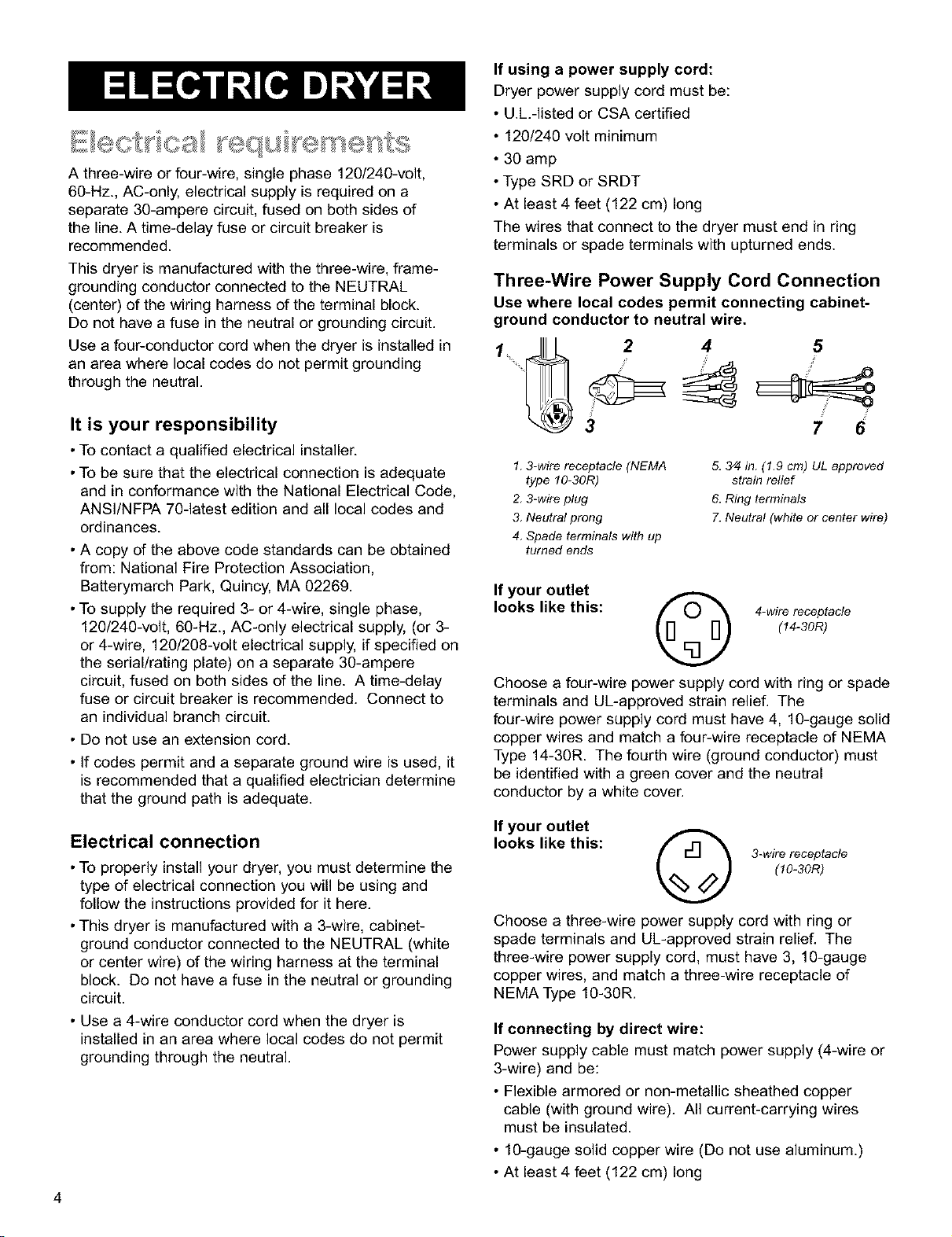
Three-Wire Power Supply Cord Connection
Use where local codes permit connecting cabinet-
ground conductor to neutral wire.
2'=d <
3 7 6
1, 3-wire receptacle (NEMA
type 10-30R)
2, 3-wire plug
3. Neutral prong
4. Spade terminals with up
turned ends
5. 3/4 in. (1.9 cm) UL approved
strain relief
6. Ring terminals
7. Neutral (white or center wire)
If your outlet
looks like this:
4-wire receptacle
(14-30R)
Choose a four-wire power supply cord with ring or spade
terminals and UL-approved strain relie[ The
four-wire power supply cord must have 4, 10-gauge solid
copper wires and match a four-wire receptacle of NEMA
Type 14-30R. The fourth wire (ground conductor) must
be identified with a green cover and the neutral
conductor by a white cover.
If your outlet
looks like this: fr'l-I "_ 3-wirereceptacle
(10-30R)
Choose a three-wire power supply cord with ring or
spade terminals and UL-approved strain relief. The
three-wire power supply cord, must have 3, 10-gauge
copper wires, and match a three-wire receptacle of
NEMA Type 10-30R.
If connecting by direct wire:
Power supply cable must match power supply (4-wire or
3-wire) and be:
• Flexible armored or non-metallic sheathed copper
cable (with ground wire). All current-carrying wires
must be insulated.
• 10-gauge solid copper wire (Do not use aluminum.)
• At least 4 feet (122 cm) long
Four-Wire Power Supply Cord Connection
Fire Hazard
Use a new UL approved 30 ampere power
supply cord.
Use a UL approved strain relief.
Disconnect power before making electrical
connections.
Connect neutral wire (white or center wire) to center
terminal (silver).
Ground wire (green or bare wire) must be connected
to green ground connector.
Connect remaining 2 supply wires to remaining 2
terminals (gold).
Securely tighten all electrical connections.
Failure to do so can result in death, fire, or
electrical shock.
GROUNDING INSTRUCTIONS
This appliance must be grounded. In the event of
malfunction or breakdown, grounding will reduce the
risk of electric shock by providing a path of least
resistance for electric current. The power supply cord
must be plugged into an appropriate outlet that is
properly installed and grounded in accordance with all
local codes and ordinances.
WARNING: Improper connection of the
equipment-grounding conductor can result in a risk of
electric shock. Check with a qualified electrician or
serviceman if your are in doubt as to whether the
appliance is properly grounded.
Do not modify the plug on the power supply cord. If it
will not fit the outlet, have a proper outlet installed by
a qualified electrician.
SAVE THESE INSTRUCTIONS
IMPORTANT: A four-wire connection is required where
local codes do not permit the use of three-wire
connections.
Four-wire Power Supply Cord
For four-wire installations, the power supply cord must
have four, No.-10 copper wires and match a four-wire
receptacle of NEMA Type 14-30R.
The fourth wire (grounding conductor) must be identified
with a green cover or bare copper wire and the neutral
conductor by a white cover.
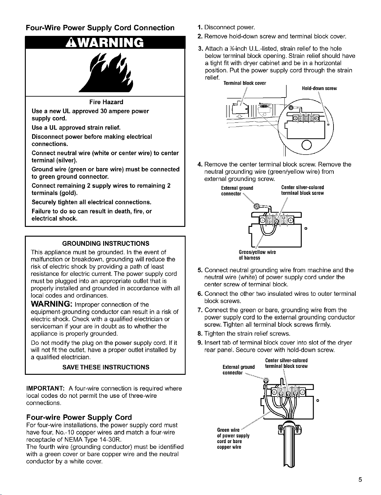
1. Disconnect power.
2. Remove hold-down screw and terminal block cover.
3. Attach a ¾-inch U.h-listed, strain relief to the hole
below terminal block opening. Strain relief should have
a tight fit with dryer cabinet and be in ahorizontal
position. Put the power supply cord through the strain
relief. Terminal block cover Hold-downscrew
@=_n %
4. Remove the center terminal block screw. Remove the
neutral grounding wire (green/yellow wire) from
external grounding screw.
Externalground Centersilver-colored
connector_terminal blockscrew
/
Green/yeg0w wire
ofharness
5. Connect neutral grounding wire from machine and the
neutral wire (white) of power supply cord under the
center screw of terminal block.
6. Connect the other two insulated wires to outer terminal
block screws.
7. Connect the green or bare, grounding wire from the
power supply cord to the external grounding conductor
screw. Tighten all terminal block screws firmly.
8. Tighten the strain relief screws.
9. Insert tab of terminal block cover into slot of the dryer
rear panel. Secure cover with hold-down screw.
Centersilver-colored
Externalground terminal blockscrew
connector
of power supply
cordor bare
copperwire
5
Four-Wire Direct Wire Connection 1. Disconnect power.
* Strip 5 inches of outer covering from end of cable.
Leave bare grounding wire at 5 inches.
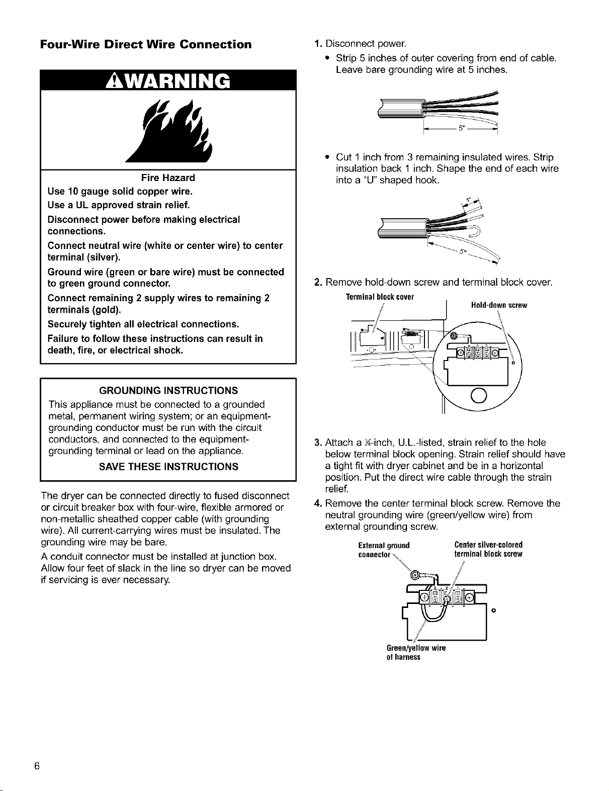
Fire Hazard
Use 10 gauge solid copper wire.
Use a UL approved strain relief.
Disconnect power before making electrical
connections.
Connect neutral wire (white or center wire) to center
terminal (silver).
Ground wire (green or bare wire) must be connected
to green ground connector.
Connect remaining 2 supply wires to remaining 2
terminals (gold).
Securely tighten all electrical connections.
Failure to follow these instructions can result in
death, fire, or electrical shock.
GROUNDING INSTRUCTIONS
This appliance must be connected to a grounded
metal, permanent wiring system; or an equipment-
grounding conductor must be run with the circuit
conductors, and connected to the equipment-
grounding terminal or lead on the appliance.
SAVE THESE INSTRUCTIONS
The dryer can be connected directly to fused disconnect
or circuit breaker box with four-wire, flexible armored or
non-metallic sheathed copper cable (with grounding
wire). All current-carrying wires must be insulated. The
grounding wire may be bare.
A conduit connector must be installed at junction box.
Allow four feet of slack in the line so dryer can be moved
if servicing is ever necessary.
* Cut 1 inchfrom 3 remaining insulated wires. Strip
insulation back 1 inch. Shape the end of each wire
into a "U" shaped hook.
2. Remove hold-down screw and terminal block cover.
Terminalblockcover Hold-downscrew
3. Attach a ¾-inch, U.L.-listed, strain relief to the hole
below terminal block opening. Strain relief should have
a tight fit with dryer cabinet and be in a horizontal
position. Put the direct wire cable through the strain
relief.
4. Remove the center terminal block screw. Remove the
neutral grounding wire (green/yellow wire) from
external grounding screw.
Externalground Centersilver-colored
connector\terminal blockscrew
Green/yellowwire
of harness
6
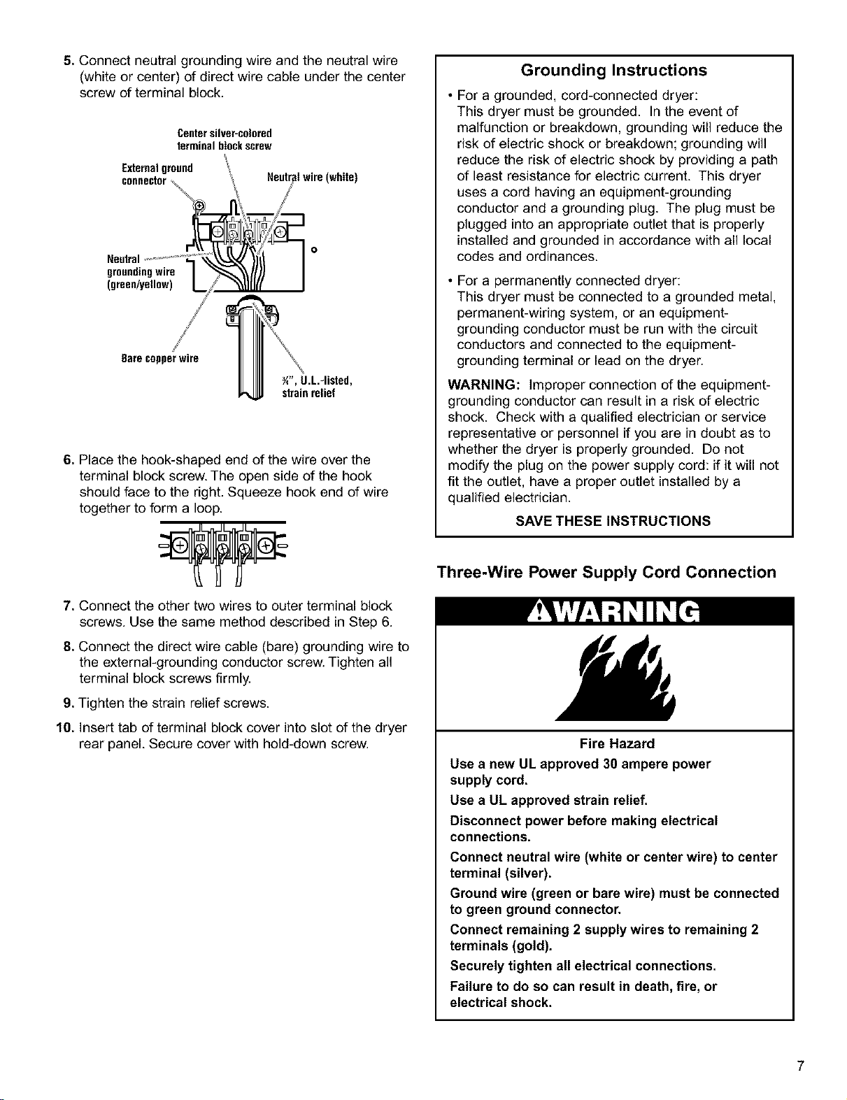
5.Connectneutralgroundingwireandtheneutralwire
(whiteorcenter)ofdirectwirecableunderthecenter
screwofterminalblock.
Centersilver-colored
terminal blockscrew
Externalground
groundingwire
(green/yellow)
Bare copperwire
Y/', U.L.-listed,
strain relief
6. Place the hook-shaped end of the wire over the
terminal block screw. The open side of the hook
should face to the right. Squeeze hook end of wire
together to form a loop.
7. Connect the other two wires to outer terminal block
screws. Use the same method described in Step 6.
8. Connect the direct wire cable (bare) grounding wire to
the external-grounding conductor screw. Tighten all
terminal block screws firmly.
9. Tighten the strain relief screws.
10. Insert tab of terminal block cover into slot of the dryer
rear panel. Secure cover with hold-down screw.
Grounding Instructions
• For a grounded, cord-connected dryer:
This dryer must be grounded. In the event of
malfunction or breakdown, grounding will reduce the
risk of electric shock or breakdown; grounding will
reduce the risk of electric shock by providing a path
of least resistance for electric current. This dryer
uses a cord having an equipment-grounding
conductor and a grounding plug. The plug must be
plugged into an appropriate outlet that is properly
installed and grounded in accordance with all local
codes and ordinances.
• For a permanently connected dryer:
This dryer must be connected to a grounded metal,
permanent-wiring system, or an equipment-
grounding conductor must be run with the circuit
conductors and connected to the equipment-
grounding terminal or lead on the dryer.
WARNING: Improper connection of the equipment-
grounding conductor can result in a risk of electric
shock. Check with a qualified electrician or service
representative or personnel if you are in doubt as to
whether the dryer is properly grounded. Do not
modify the plug on the power supply cord: if it will not
fit the outlet, have a proper outlet installed by a
qualified electrician.
SAVE THESE INSTRUCTIONS
Three-Wire Power Supply Cord Connection
Fire Hazard
Use a new UL approved 30 ampere power
supply cord.
Use a UL approved strain relief.
Disconnect power before making electrical
connections.
Connect neutral wire (white or center wire) to center
terminal (silver).
Ground wire (green or bare wire) must be connected
to green ground connector.
Connect remaining 2 supply wires to remaining 2
terminals (gold).
Securely tighten all electrical connections.
Failure to do so can result in death, fire, or
electrical shock.
7
1.Disconnectpower.
2.Removehold-downscrewandterminalblockcover.
Terminal blockcover Hold-downscrew
4
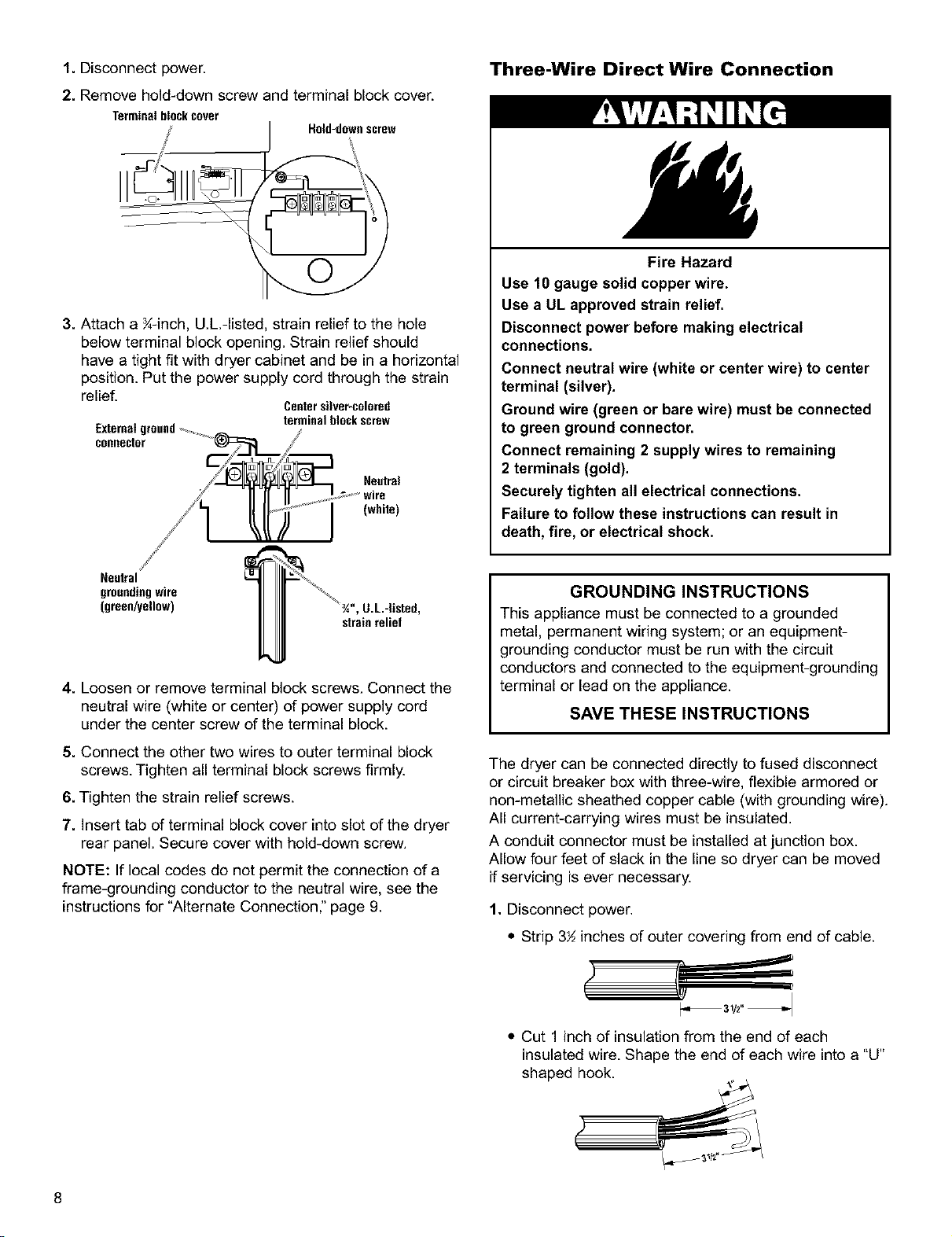
3. Attach a K-inch, U.L.-listed, strain relief to the hole
below terminal block opening. Strain relief should
have a tight fit with dryer cabinet and be in a horizontal
position. Put the power supply cord through the strain
relief. Centersilver-colored
terminal block screw
Externalground............,_ /
connector
/_/1 ll lt'_f'sJ "j" w'rn
...... (whde),
/
Neutral
grounding wire
(green/yellow) ', U.L-Usted,
strain relief
4. Loosen or remove terminal block screws. Connect the
neutral wire (white or center) of power supply cord
under the center screw of the terminal block.
5. Connect the other two wires to outer terminal block
screws. Tighten all terminal block screws firmly.
6. Tighten the strain relief screws.
7. Insert tab of terminal block cover into slot of the dryer
rear panel. Secure cover with hold-down screw.
NOTE: If local codes do not permit the connection of a
frame-grounding conductor to the neutral wire, see the
instructionsfor "Alternate Connection," page 9.
Three-Wire Direct Wire Connection
Fire Hazard
Use 10 gauge solid copper wire.
Use a UL approved strain relief.
Disconnect power before making electrical
connections.
Connect neutral wire (white or center wire) to center
terminal (silver).
Ground wire (green or bare wire) must be connected
to green ground connector.
Connect remaining 2 supply wires to remaining
2 terminals (gold).
Securely tighten all electrical connections.
Failure to follow these instructions can result in
death, fire, or electrical shock.
GROUNDING INSTRUCTIONS
This appliance must be connected to a grounded
metal, permanent wiring system; or an equipment-
grounding conductor must be run with the circuit
conductors and connected to the equipment-grounding
terminal or lead on the appliance.
SAVE THESE INSTRUCTIONS
The dryer can be connected directly to fused disconnect
or circuit breaker box with three-wire, flexible armored or
non-metallic sheathed copper cable (with grounding wire).
All current-carrying wires must be insulated.
A conduit connector must be installed at junction box.
Allow four feet of slack in the line so dryer can be moved
if servicing is ever necessary.
1. Disconnect power.
• Strip 3½ inches of outer covering from end of cable.
• Cut 1 inch of insulation from the end of each
insulated wire. Shape the end of each wire into a "U"
shaped hook.
8
2.Removehold-downscrewandterminalblockcover.
Terminal blockcover Hold-downscrew
3. Attach a _-inch, U.L.-listed, strain relief to the hole
below terminal block opening. Strain relief should have
a tight fit with dryer cabinet and be in a horizontal
position. Put the direct wire cable through the strain
relief.
Centersilver-colored
Externalground terminal blockscrew
coeeector %%
w,re
///__" 0 (white)
/L- ....
Neutralgrounding
wire (green/yellow)
_", U.L.-listed,
strainrelief
Alternate Connection:
If local codes do not permit the connection of a frame-
grounding conductor to the neutral wire:
1. Disconnect power.
2. Make sure the power supply cord or direct wire cable is
in place.
3. Remove the neutral grounding wire (green/yellow wire)
from external grounding connector screw. Loosen or re-
move terminal block screws. Connect neutral grounding
wire and the neutral wire (white or center) of power
supply cord or direct wire cable under the center screw
of the terminal block.
4. Connect the other two wires to outer terminal block
screws. Tighten all terminal block screws firmly.
5. Tighten the strain relief screws.
6. Insert tab of terminal block cover into slot of the dryer
rear panel. Secure cover with hold-down screw.
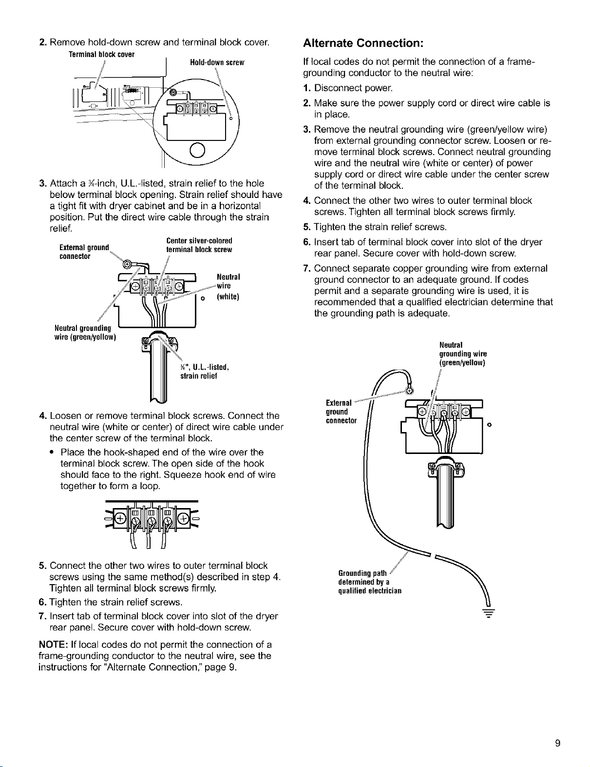
7. Connect separate copper grounding wire from external
ground connector to an adequate ground. If codes
permit and a separate grounding wire is used, it is
recommended that a qualified electrician determine that
the grounding path is adequate.
Neutral
groundingwire
(green/yellow)
4. Loosen or remove terminal block screws. Connect the
neutral wire (white or center) of direct wire cable under
the center screw of the terminal block.
•Place the hook-shaped end of the wire over the
terminal block screw. The open side of the hook
should face to the right. Squeeze hook end of wire
together to form a loop.
5. Connect the other two wires to outer terminal block
screws using the same method(s) described in step 4.
Tighten all terminal block screws firmly.
6. Tighten the strain relief screws.
7. Insert tab of terminal block cover into slot of the dryer
rear panel. Secure cover with hold-down screw.
NOTE: If local codes do not permit the connection of a
frame-grounding conductor to the neutral wire, see the
instructions for "Alternate Connection," page 9.
External
ground
connector
determinedby a
qualified electrician
m
9
Explosion Hazard
Use a new AGA or CSA approved flexible gas
supply line.
Install a shut-off valve.
Securely tighten all gas connections.
If connected to LP, have a qualified person make
sure gas pressure does not exceed 13" (33 cm)
water column. Examples of a qualified person
include licensed heating personnel, authorized
gas company personnel, and authorized service
personnel.
Failure to do so can result in death, explosion,
or fire.
OBSERVE ALL GOVERNING CODES AND
ORDINANCES.
•This installation must conform with local codes, or in
absence of local codes with the National Fuel Gas
Code ANSI Z223.1/NFPA 54.
•The design of this dryer has been certified by the CSA
International for use at altitudes up to 10,000 feet
(3048 m) above sea level at the B.T.U. rating indicated
on the model/serial plate. Burner input adjustments are
not required when the dryer is operated up to this
elevation.
When installed above 10,000 feet (3048 m), a four
percent (4%) reduction of the burner B.T.U. rating
shown on the model/serial plate is required for each
1,000 foot (305 m) increase in elevation. For assistance
when converting to other gas types and/or installing
above 10,000 feet (3048 m) elevation, contact your
local service company.
• Check that dryer is equipped with the correct burner for
the particular type of gas used. Burner information can
be found on the serial/rating plate in the door well of
the appliance. If this information does not agree with
the type of gas available, see your dealer.
• This dryer is equipped for use with NATURAL GAS. It
is certified by CSA International for LR (propane and
butane) gases with appropriate conversion. No attempt
shall be made to convert the appliance from the gas
specified on the serial/rating plate for use with a
different gas without consulting the serving gas
supplier. Conversion must be done by a qualified
service technician. Gas conversion kit part
numbers are listed on the gas valve burner base.
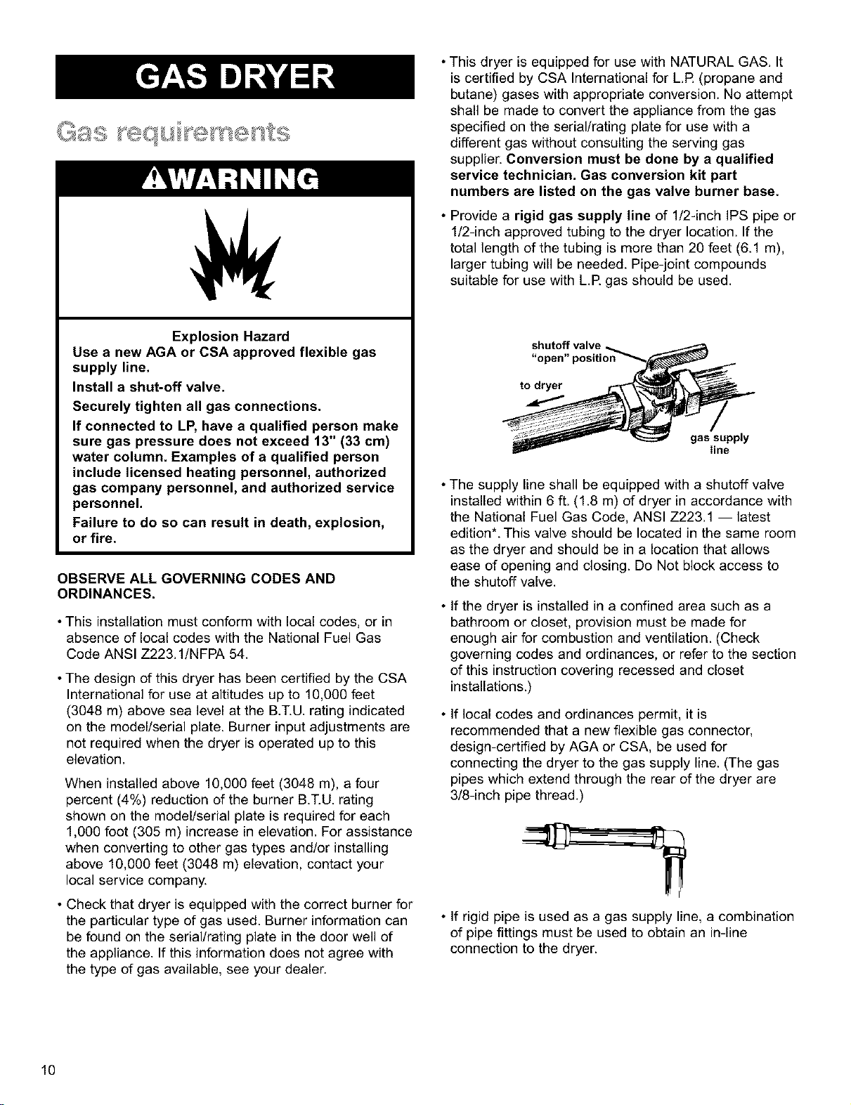
• Provide a rigid gas supply line of 1/2-inch IPS pipe or
1/2-inch approved tubing to the dryer location. If the
total length of the tubing is more than 20 feet (6.1 m),
larger tubing will be needed. Pipe-joint compounds
suitable for use with LR gas should be used.
"open" position
to dryer
gas supply
line
• The supply line shall be equipped with a shutoff valve
installed within 6 ft. (1.8 m) of dryer in accordance with
the National Fuel Gas Code, ANSI Z223.1 -- latest
edition*. This valve should be located in the same room
as the dryer and should be in a location that allows
ease of opening and closing. Do Not block access to
the shutoff valve.
• If the dryer is installed in a confined area such as a
bathroom or closet, provision must be made for
enough air for combustion and ventilation. (Check
governing codes and ordinances, or refer to the section
of this instruction covering recessed and closet
installations.)
• If local codes and ordinances permit, it is
recommended that a new flexible gas connector,
design-certified by AGA or CSA, be used for
connecting the dryer to the gas supply line. (The gas
pipes which extend through the rear of the dryer are
3/8-inch pipe thread.)
• If rigid pipe is used as a gas supply line, a combination
of pipe fittings must be used to obtain an in-line
connection to the dryer.
10
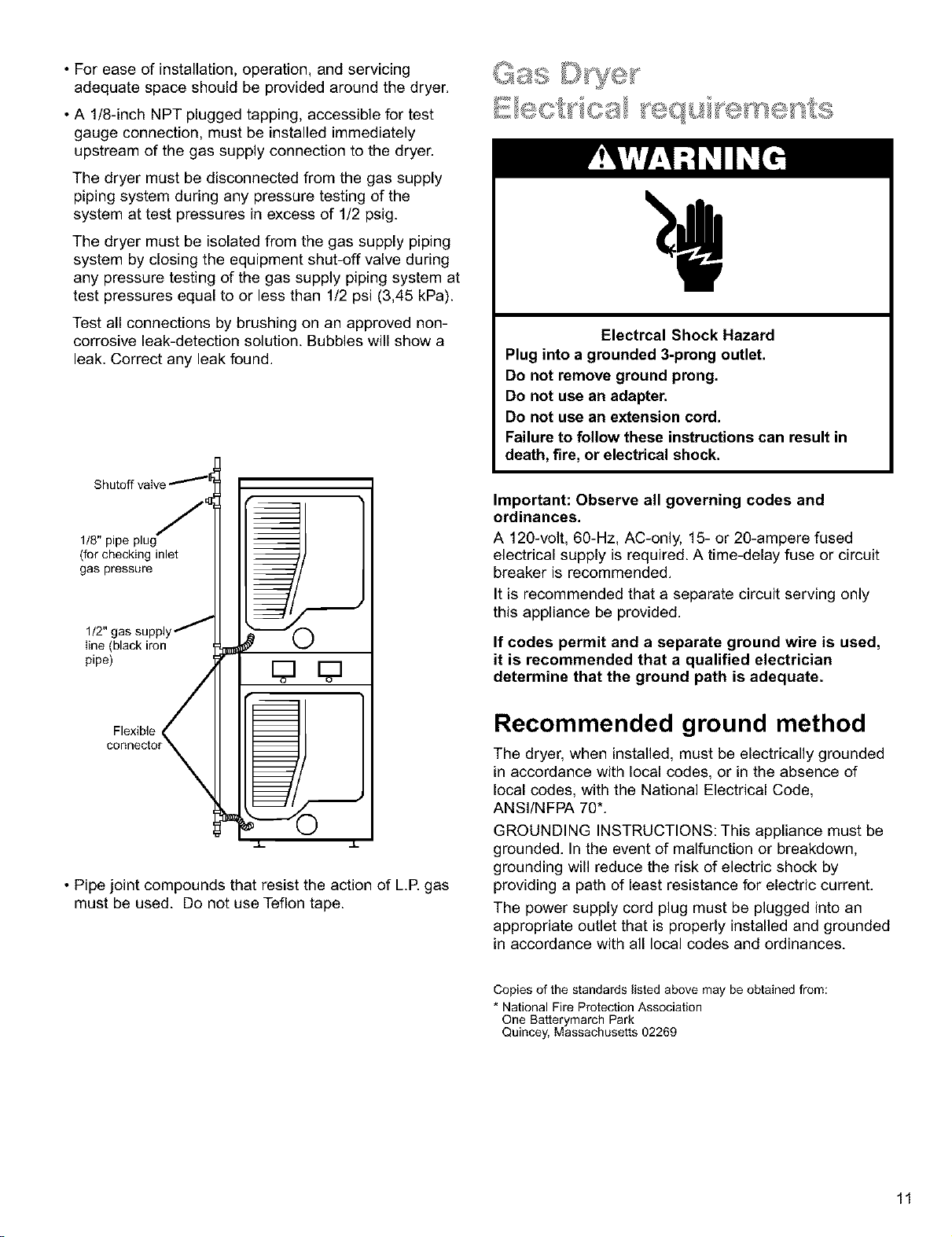
•Foreaseofinstallation,operation,andservicing
adequatespaceshouldbeprovidedaroundthedryer.
•A1/8-inchNPTpluggedtapping,accessiblefortest
gaugeconnection,mustbeinstalledimmediately
upstreamofthegassupplyconnectiontothedryer.
Thedryermustbedisconnectedfromthegassupply
pipingsystemduringanypressuretestingofthe
systemattestpressuresinexcessof 1!2psig.
Thedryermustbeisolatedfromthegassupplypiping
systembyclosingtheequipmentshut-offvalveduring
anypressuretestingofthegassupplypipingsystemat
testpressuresequaltoorlessthan1/2psi(3,45kPa).
Testallconnectionsbybrushingonanapprovednon-
corrosiveleak-detectionsolution.Bubbleswillshowa
leak.Correctanyleakfound. Electrcal Shock Hazard
Plug into a grounded 3-prong outlet.
Do not remove ground prong.
Do not use art adapter.
Do not use an extension cord.
Failure to follow these instructions can result in
death, fire, or electrical shock.
1/8" pipe plug
(for checking inlet
gas pressure
line (black iron
pipe)
Flexible r;
connecto
0
• Pipe joint compounds that resist the action of L.R gas
must be used. Do not use Teflon tape.
Important: Observe all governing codes and
ordinances.
A 120-volt, 60-Hz, AC-only, 15-or 20-ampere fused
electrical supply is required. A time-delay fuse or circuit
breaker is recommended.
It is recommended that a separate circuit serving only
this appliance be provided.
If codes permit and a separate ground wire is used,
it is recommended that a qualified electrician
determine that the ground path is adequate.
Recommended ground method
The dryer, when installed, must be electrically grounded
in accordance with local codes, or in the absence of
local codes, with the National Electrical Code,
ANSI/NFPA 70*.
GROUNDING INSTRUCTIONS: This appliance must be
grounded. In the event of malfunction or breakdown,
grounding will reduce the risk of electric shock by
providing a path of least resistance for electric current.
The power supply cord plug must be plugged into an
appropriate outlet that is properly installed and grounded
in accordance with all local codes and ordinances.
Copies of the standards listed above may be obtained from:
* National Fire Protection Association
One Batterymarch Park
Quincey, Massachusetts 02269
11
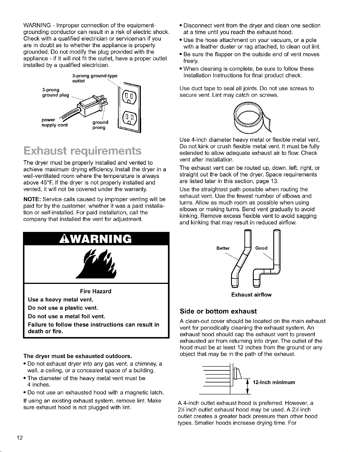
WARNING- Improperconnectionoftheequipment-
groundingconductorcanresultinariskofelectricshock.
Checkwithaqualifiedelectricianorservicemanifyou
areindoubtastowhethertheapplianceisproperly
grounded.Donotmodifytheplugprovidedwiththe
appliance- ifitwillnotfittheoutlet,haveaproperoutlet
installedbyaqualifiedelectrician.
3-prong ground-type
outlet
3-prong (_
ground_
power _/_r_ u)
ground
supply cord prong _
The dryer must be properly installed and vented to
achieve maximum drying efficiency. Install the dryer in a
well-ventilated room where the temperature is always
above 45°R If the dryer is not properly installed and
vented, it will not be covered under the warranty.
NOTE: Service calls caused by improper venting will be
paid for by the customer, whether it was a paid installa-
tion or self-installed. For paid installation, call the
company that installed the vent for adjustment.
Fire Hazard
Use a heavy metal vent.
Do not use a plastic vent.
Do not use a metal foil vent.
Failure to follow these instructions can result in
death or fire.
The dryer must be exhausted outdoors.
•Do not exhaust dryer into any gas vent, a chimney, a
wall, a ceiling, or a concealed space of a building.
• The diameter of the heavy metal vent must be
4 inches.
• Do not use an exhausted hood with a magnetic latch.
If using an existing exhaust system, remove lint. Make
sure exhaust hood is not plugged with lint.
• Disconnect vent from the dryer and clean one section
at a time until you reach the exhaust hood.
• Use the hose attachment on your vacuum, or a pole
with a feather duster or rag attached, to clean out lint.
• Be sure the flapper on the outside end of vent moves
freely.
• When cleaning is complete, be sure to follow these
Installation Instructions for final product check.
Use duct tape to seal all joints. Do not use screws to
secure vent. Lint may catch on screws.
Use 4-inch diameter heavy metal or flexible metal vent.
Do not kink or crush flexible metal vent. It must be fully
extended to allow adequate exhaust air to flow. Check
vent after installation.
The exhaust vent can be routed up, down, left, right, or
straight out the back of the dryer. Space requirements
are listed later in this section, page 13.
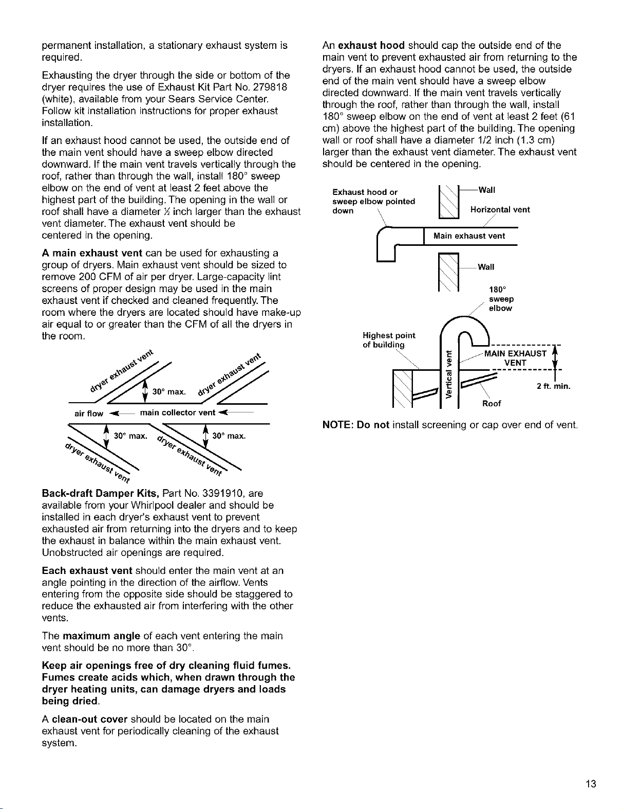
Use the straightest path possible when routing the
exhaust vent. Use the fewest number of elbows and
turns. Allow as much room as possible when using
elbows or making turns. Bend vent gradually to avoid
kinking. Remove excess flexible vent to avoid sagging
and kinking that may result in reduced airflow.
eood
Exhaust airflow
Side or bottom exhaust
A clean-out cover should be located on the main exhaust
vent for periodically cleaning the exhaust system. An
exhaust hood should cap the exhaust vent to prevent
exhausted air from returning into dryer. The outlet of the
hood must be at least 12 inches from the ground or any
object that may be in the path of the exhaust.
- 12-inch minimum
A 4-inch outlet exhaust hood is preferred. However, a
2½ inch outlet exhaust hood may be used. A 2½ inch
outlet creates a greater back pressure than other hood
types. Smaller hoods increase drying time. For
12
permanentinstallation,astationaryexhaustsystemis
required.
Exhaustingthedryerthroughthesideorbottomofthe
dryerrequirestheuseofExhaustKitPartNo.279818
(white),availablefromyourSearsServiceCenter.
Followkitinstallationinstructionsforproperexhaust
installation.
If an exhaust hood cannot be used, the outside end of
the main vent should have a sweep elbow directed
downward. If the main vent travels vertically through the
roof, rather than through the wall, install 189° sweep
elbow on the end of vent at least 2 feet above the
highest part of the building. The opening in the wall or
roof shall have a diameter ½inch larger than the exhaust
vent diameter. The exhaust vent should be
centered in the opening.
Amain exhaust vent can be used for exhausting a
group of dryers. Main exhaust vent should be sized to
remove 200 CFM of air per dryer. Large-capacity lint
screens of proper design may be used in the main
exhaust vent if checked and cleaned frequently. The
room where the dryers are located should have make-up
air equal to or greater than the CFM of all the dryers in
the room.
_._e,_ 30" max. e_"et"k"
air flow _1: main collector vent -_
Back-draft Damper Kits, Part No. 3391910, are
available from your Whirlpool dealer and should be
installed in each dryeds exhaust vent to prevent
exhausted air from returning into the dryers and to keep
the exhaust in balance within the main exhaust vent.
Unobstructed air openings are required.
Each exhaust vent should enter the main vent at an
angle pointing in the direction of the airflow. Vents
entering from the opposite side should be staggered to
reduce the exhausted air from interfering with the other
vents.
The maximum angle of each vent entering the main
vent should be no more than 30 °.
Keep air openings free of dry cleaning fluid fumes.
Fumes create acids which, when drawn through the
dryer heating units, can damage dryers and loads
being dried.
Aclean-out cover should be located on the main
exhaust vent for periodically cleaning of the exhaust
system.
An exhaust hood should cap the outside end of the
main vent to prevent exhausted air from returning to the
dryers. If an exhaust hood cannot be used, the outside
end of the main vent should have a sweep elbow
directed downward. If the main vent travels vertically
through the roof, rather than through the wall, install
180° sweep elbow on the end of vent at least 2 feet (61
cm) above the highest part of the building. The opening
wall or roof shall have a diameter 1/2 inch (1.3 cm)
larger than the exhaust vent diameter. The exhaust vent
should be centered in the opening.
Exhaust hood or i \ = ,,,ix \_ vail
U.o
sweep elbow pointed
down ri_ntal vent
\
ri i Main exhaust vent
Wall
180°
sweep
__ elbow
/MAIN EXHAUST
_V.E...T._ n.
Roof
Highest point
of building
NOTE: Do not install screening or cap over end of vent.
13
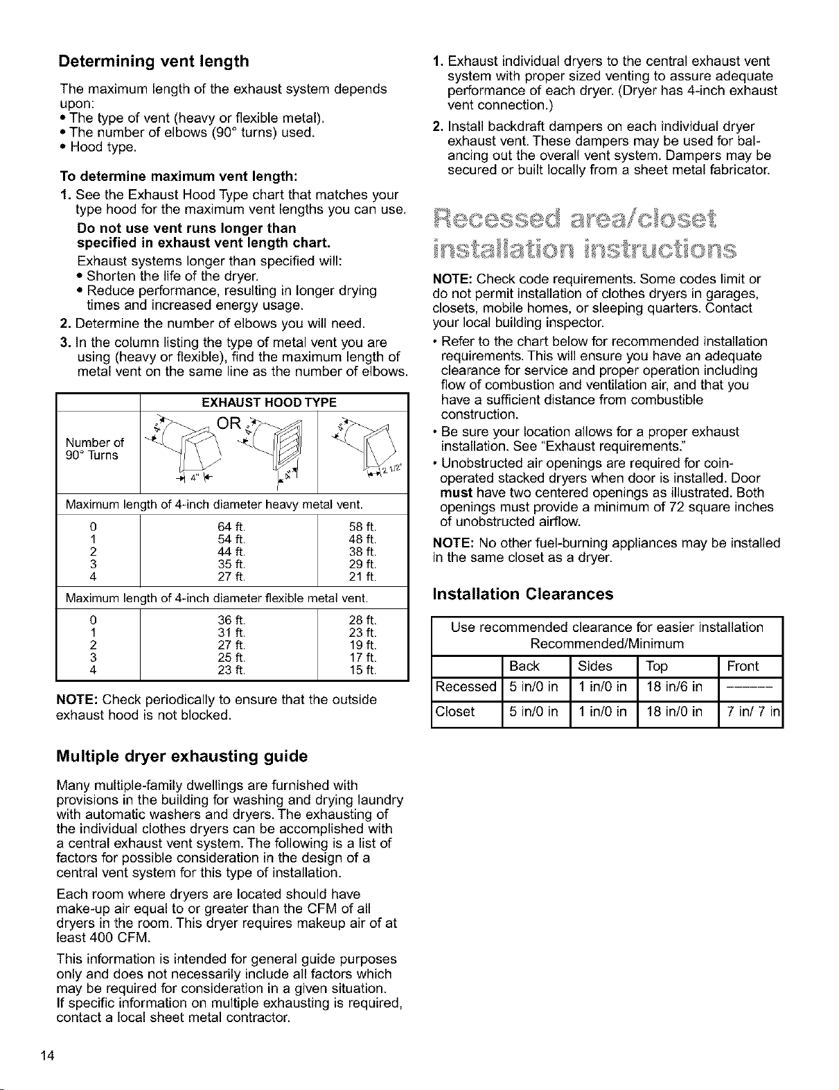
Determining vent length
The maximum length of the exhaust system depends
upon:
• The type of vent (heavy or flexible metal).
• The number of elbows (90° turns) used.
• Hood type.
To determine maximum vent length:
1. See the Exhaust Hood Type chart that matches your
type hood for the maximum vent lengths you can use.
Do not use vent runs longer than
specified in exhaust vent length chart.
Exhaust systems longer than specified will:
•Shorten the life of the dryer.
• Reduce performance, resulting in longer drying
times and increased energy usage.
2. Determine the number of elbows you will need.
3. In the column listing the type of metal vent you are
using (heavy or flexible), find the maximum length of
metal vent on the same line as the number of elbows.
EXHAUST HOOD TYPE
Number of
90° Turns
Maximum length of 4dnch diameter heavy metal vent.
0 64 ft. 58 ft,
1 54 ft. 48 ft,
2 44 ft. 38 ft,
3 35 ft. 29 ft,
4 27 ft. 21 ft.
Maximum length of 4dnch diameter flexible metal vent.
0 36 ft. 28 ft,
1 31 ft. 23 ft,
2 27 ft. 19 ft,
3 25ft. 17ft,
4 23ft. 15ft.
NOTE: Check periodically to ensure that the outside
exhaust hood is not blocked.
1. Exhaust individual dryers to the central exhaust vent
system with proper sized venting to assure adequate
performance of each dryer. (Dryer has 4-inch exhaust
vent connection.)
2. Install backdraft dampers on each individual dryer
exhaust vent. These dampers may be used for bal-
ancing out the overall vent system. Dampers may be
secured or built locally from a sheet metal fabricator.
NOTE: Check code requirements. Some codes limit or
do not permit installation of clothes dryers in garages,
closets, mobile homes, or sleeping quarters. Contact
your local building inspector.
• Refer to the chart below for recommended installation
requirements. This will ensure you have an adequate
clearance for service and proper operation including
flow of combustion and ventilation air, and that you
have a sufficient distance from combustible
construction.
• Be sure your location allows for a proper exhaust
installation. See "Exhaust requirements."
• Unobstructed air openings are required for coin-
operated stacked dryers when door is installed. Door
must have two centered openings as illustrated. Both
openings must provide a minimum of 72 square inches
of unobstructed airflow.
NOTE: No other fuel-burning appliances may be installed
in the same closet as a dryer.
Installation Clearances
Use recommended clearance for easier installation
Recommended/Minimum
Back Sides Top Front
Recessed 5 in/0 in 1 in/0 in 18 in/6 in
Closet 5 in/0 in 1 in/0 in 18 in/0 in 7 in/7 in
Multiple dryer exhausting guide
Many multiple-family dwellings are furnished with
provisions in the building for washing and drying laundry
with automatic washers and dryers. The exhausting of
the individual clothes dryers can be accomplished with
a central exhaust vent system. The following is a list of
factors for possible consideration in the design of a
central vent system for this type of installation.
Each room where dryers are located should have
make-up air equal to or greater than the CFM of all
dryers in the room. This dryer requires makeup air of at
least 400 CFM.
This information is intended for general guide purposes
only and does not necessarily include all factors which
may be required for consideration in a given situation.
If specific information on multiple exhausting is required,
contact a local sheet metal contractor.
14

Recessed area and closet installation
requirements Recessed
£
%W_'>, ._*" I I Q_I_>,I['_I I IC_I=I IJ I I
Installing coin-slide mechanism
1. Your dryers are set for 60 minutes of drying. If you
wish, you may change to 30 to 45 minutes drying with
the cams provided. See "Replacing nlyon timing cams
on accumulator mechanism."
2. Open dryer control panel. Let it rest on the bottom
edge of the opening.
The coin slide is set for $1. To change vend price, follow
instructions included with coin chute.
I
0'_
0
0
Side View
Closet
48 sq.
]
m
J
Closet
door
O
Front View
Control panel
Mounting Screws
3. Insert the coin slide mechanism through the opening
to the left of the control panel. You may have to loosen
four mounting screws for proper fit.
4. Secure coin slide mechanism from inside control
panel with _-inch coin slide mounting rod included
with slide mechanism. Use _" open-end wrench to
tighten rod.
5. Repeat steps 3 and 4 for inserting coin slide
mechanism for right side. Close the control panel.
15
Coin box adjustment
The tight fit of the money box is set at the factory.
Customer may loosen fit as desired by loosening the
slotted nuts.
Keep a record of all coin-box key numbers. A lost key
can only be replaced if ordered by key number from
Sears Parts. The key number is located both on the key
and behind the end panel of the coin box. If the key
number is not available, the lock must be drilled out to
remove the coin box.
Final installation connection
1. Connect exhaust vent to exhaust outlet of the dryer.
2. Carefully move dryer into permanent location. Provide
at least the minimum installation clearances between
dryer and rear wall. See the chart. This will ensure
you have an adequate clearance for service and
proper operation including flow of combustion and
ventilation air, and that you have sufficient
distance from combustible construction.
3. When dryer is in final position, place level on top of
the dryers or collar, first side to side; then front to
back. If the dryer is not level, adjust the legs of the
dryer up or down until the dryer is level.
4. Plug in dryer or connect power.
5. Double check your installation, reviewing each step.
Be sure all packing materials have been removed and
properly disposed of, and that all tools have been put
away.
6. Wipe each dryer drum thoroughly with a damp cloth.
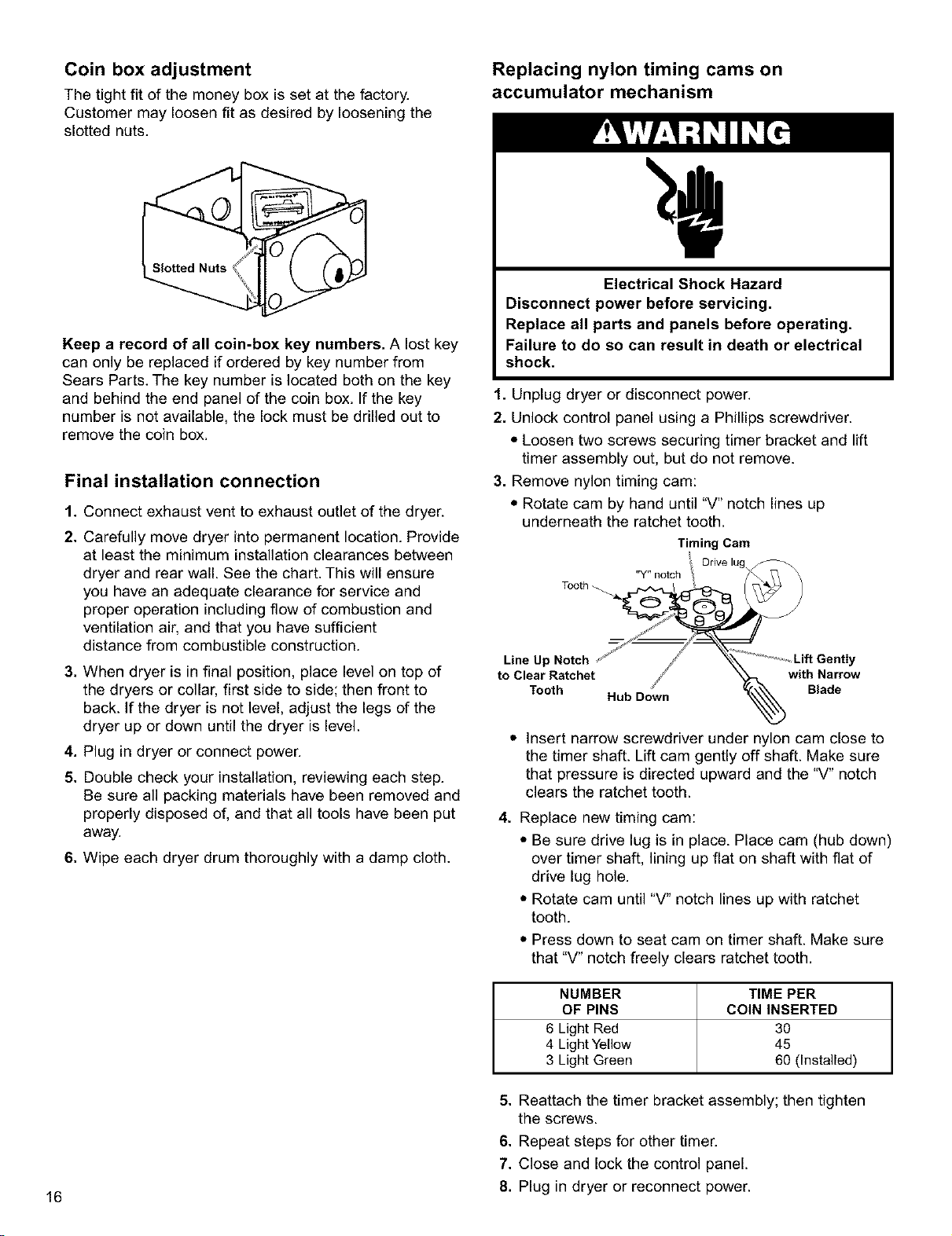
Replacing nylon timing cams on
accumulator mechanism
Electrical Shock Hazard
Disconnect power before servicing.
Replace all parts and panels before operating.
Failure to do so can result in death or electrical
shock.
1. Unplug dryer or disconnect power.
2. Unlock control panel using a Phillips screwdriver.
• Loosen two screws securing timer bracket and lift
timer assembly out, but do not remove.
3. Remove nylon timing cam:
• Rotate cam by hand until "V" notch lines up
underneath the ratchet tooth.
Timing Cam
Orive lug
"Y" notch
-h
Line Up Notch ,' j _-k _Lift Gently
to Clear Ratchet ji _ with Narrow
Tooth Hub D0_wn %Blade
• Insert narrow screwdriver under nylon cam close to
the timer shaft. Lift cam gently off shaft. Make sure
that pressure is directed upward and the "V" notch
clears the ratchet tooth.
4. Replace new timing cam:
• Be sure drive lug is in place. Place cam (hub down)
over timer shaft, lining up flat on shaft with flat of
drive lug hole.
• Rotate cam until "V" notch lines up with ratchet
tooth.
• Press down to seat cam on timer shaft. Make sure
that "V" notch freely clears ratchet tooth.
NUMBER TIME PER
OF PINS COIN INSERTED
6 Light Red 30
4 Light Yellow 45
3 Light Green 60 (Installed)
16
5. Reattach the timer bracket assembly; then tighten
the screws.
6. Repeat steps for other timer.
7. Close and lock the control panel.
8. Plug in dryer or reconnect power.
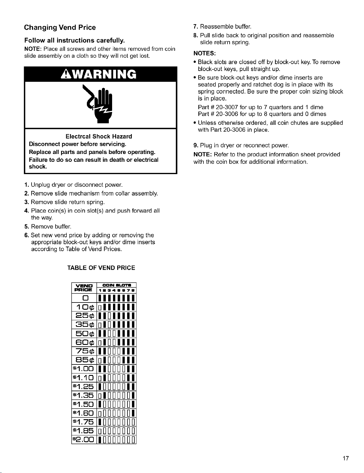
Changing Vend Price
Follow all instructions carefully.
NOTE: Place all screws and other items removed from coin
slide assembly on a cloth so they will not get lost.
Electrcal Shock Hazard
Disconnect power before servicing.
Replace all parts and panels before operating.
Failure to do so can result in death or electrical
shock.
1. Unplug dryer or disconnect power.
2. Remove slide mechanism from collar assembly.
3. Remove slide return spring.
4. Place coin(s) in coin slot(s) and push forward all
the way.
5. Remove buffer.
6. Set new vend price by adding or removing the
appropriate block-out keys and/or dime inserts
according to Table of Vend Prices.
TABLE OF VEND PRICE
VEND COIN IlI.I_"IS
PRICE lm341Ee?8
oIIIIIII
Io¢ DI IIII
25¢ I1_1111
35¢ DI IIII
5o¢ II_DIII
6o¢ DI Dill
75¢ IIDDDI 1
85¢ DIDDDI
=1.oo I IllllllH I
•1.1o DIllllllH I
=1.25 IDDDDDI
=1.35 DIIlllllllll
=1.5o IDDDDDD
=18o nlqlqlqlq00
=1.75 IBBBBBB
=1.85 oOOOOOO
=2.oo I0000000
7. Reassemble buffer.
8. Pull slide back to original position and reassemble
slide return spring.
NOTES:
* Black slots are closed off by block-out key. To remove
block-out keys, pull straight up.
* Be sure block-out keys and/or dime inserts are
seated properly and ratchet dog is in place with its
spring connected. Be sure the proper coin sizing block
is in place.
Part # 20-3007 for up to 7 quarters and 1 dime
Part # 20-3006 for up to 8 quarters and 0 dimes
* Unless otherwise ordered, all coin chutes are supplied
with Part 20-3006 in place.
9. Plug in dryer or reconnect power.
NOTE: Refer to the product information sheet provided
with the coin box for additional information.
17
OPERATING THE
DRYER
Read operating instructions before operating the dryer.
(Located on console.)
Explosion Hazard
Keep flammable materials and vapors, such as
gasoline, away from dryer.
Do not dry anything that has ever had anything
flammable on it (even after washing).
Failure to follow these instructions can result in
death, explosion, or fire.
Fire Hazard
No washer can completely remove oil.
Do not dry anything that has ever had any type of
oil on it (including cooking oils).
Items containing foam, rubber, or plastic must be
dried on a clothesline or by using an Air Cycle.
Failure to follow these instructions can result in
death or fire.
1. The lint screen must be cleaned before or after each
load. A blocked screen or exhaust will cause slow drying
and other problems.
2. If the dryer will not operate, check the following to be
sure:
•Electrical supply is not connected
• Fuse is good and fits tightly
• Door is closed, dryer will not operate with the door
open.
• Proper coins are inserted. Push slide in and slowly
pull out.
• Push-to-start button is pushed in firmly
Removing accumulated lint
From Inside the Dryer Cabinet.
Lint should be removed every 2 years of more often,
depending on dryer usage. Cleaning should be done by
a qualified person.
From the ExhaustVent.
Clean exhaust vent periodically, depending on use, but
at least every 2 years, or when installing your dryer in a
new location.
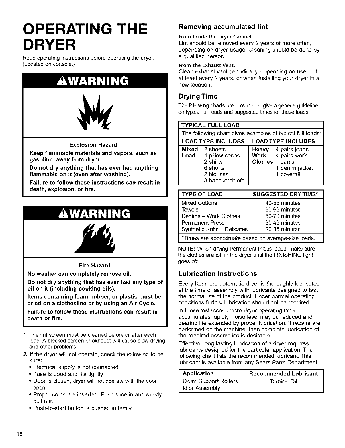
Drying Time
The following charts are provided to give a general guideline
on typical full loads and suggested times for these loads.
TYPICAL FULL LOAD
The following chart gives examples of typical full loads:
LOAD TYPE INCLUDES LOAD TYPE INCLUDES
Mixed 2 sheets Heavy 4 pairs jeans
Load 4 pillow cases Work 4 pairs work
2 shirts Clothes pants
6 shorts 1 denim jacket
2 blouses 1 coverall
8 handkerchiefs
TYPE OF LOAD SUGGESTED DRYTIME*
Mixed Cottons 40-55 minutes
Towels 50-65 minutes
Denims - Work Clothes 50-70 minutes
Permanent Press 30-45 minutes
Synthetic Knits - Delicates 20-35 minutes
*Times are approximate based on average-size loads.
NOTE: When drying Permanent Press loads, make sure
the clothes are left in the dryer until the FINISHING light
goes off.
Lubrication Instructions
Every Kenmore automatic dryer is thoroughly lubricated
at the time of assembly with lubricants designed to last
the normal life of the product. Under normal operating
conditions further lubrication should not be required.
In those instances where dryer operating time
accumulates rapidly, noise level may be reduced and
bearing life extended by proper lubrication. If repairs are
performed on the machine, then complete lubrication of
the repaired assemblies is desirable.
Effective, long-lasting lubrication of a dryer requires
lubricants designed for the particular application. The
following chart lists the recommended lubricant. This
lubricant is available from any Sears Parts Department.
tpplication
Drum Support Rollers
Idler Assembly RecommendedTurbineoilLubricant t
18
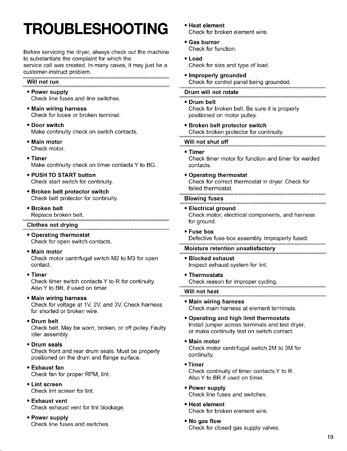
TROUBLESHOOTING •Heat element
Check for broken element wire.
Before servicing the dryer, always check out the machine
to substantiate the complaint for which the
service call was created. In many cases, it may just be a
customer-instruct problem.
Will not run
•Power supply
Check line fuses and line switches.
•Main wiring harness
Check for loose or broken terminal.
•Door switch
Make continuity check on switch contacts.
•Main motor
Check motor.
•Timer
Make continuity check on timer contacts Y to BG.
•PUSH TO START button
Check start switch for continuity.
• Broken belt protector switch
Check belt protector for continuity.
•Broken belt
Replace broken belt.
Clothes not drying
• Operating thermostat
Check for open switch contacts.
•Main motor
Check motor centrifugal switch M2 to M3 for open
contact.
•Timer
Check timer switch contacts Y to R for continuity.
Also Y to BR, if used on timer.
•Main wiring harness
Check for voltage at 1V, 2V, and 3V. Check harness
for shorted or broken wire.
•Drum belt
Check belt. May be worn, broken, or off pulley. Faulty
idler assembly.
•Drum seals
Check front and rear drum seals. Must be properly
positioned on the drum and flange surface.
•Exhaust fan
Check fan for proper RPM, lint.
• Lint screen
Check lint screen for lint.
•Exhaust vent
Check exhaust vent for lint blockage.
•Power supply
Check line fuses and switches.
•Gas burner
Check for function.
•Load
Check for size and type of load.
•Improperly grounded
Check for control panel being grounded.
Drum will not rotate
•Drum belt
Check for broken belt. Be sure it is properly
positioned on motor pulley.
•Broken belt protector switch
Check broken protector for continuity.
Will not shut off
•Timer
Check timer motor for function and timer for welded
contacts.
•Operating thermostat
Check for correct thermostat in dryer. Check for
failed thermostat.
Blowing fuses
•Electrical ground
Check motor, electrical components, and harness
for ground.
•Fuse box
Defective fuse-box assembly. Improperly fused.
Moisture retention unsatisfactory
•Blocked exhaust
Inspect exhaust system for lint.
•Thermostats
Check reason for improper cycling.
Will not heat
•Main wiring harness
Check main harness at element terminals.
•Operating and high limit thermostats
Install jumper across terminals and test dryer,
or make continuity test on switch contact.
•Main motor
Check motor centrifugal switch 2M to 3M for
continuity.
•Timer
Check continuity of timer contacts Y to R.
Also Y to BR if used on timer.
•Power supply
Check line fuses and switches.
•Heat element
Check for broken element wire.
• No gas flow
Check for closed gas supply valves. 19
Troubleshooting (cont.)
Drying temperature too high
•Operating thermostat
Check for lint that may insulate thermostat from
exhaust air. Check thermostat for function.
Motor runs with door open
•Door switch
Check door switch for function and switch clip
actuating arm for proper switch plunger actuation.
Noise
•Loose component
Secure component.
• Idler assembly
Check alignment and bearing assembly.
•Belt
Replace belt.
•Motor
Check motor.
•Lint
Remove lint from rear drum groove.
•Front drum bearings
Lubricate or replace bearings. If loose, fasten Delrin
bearing ring to drum flange with silastic or, if needed,
replace Delrin ring.
•Support roller assemblies
Replace roller and/or shaft.
•Baffle
Tighten assembled baffle.
•Blower
Foreign matter in blower housing.
Clothes "bailing" complaints
• Large garments (sheets, spreads) "bailing"
instead of tumbling
Check to see if dryer is being overloaded. Check
drum speed (48 -+3 RPM).
Odors
•Have you recently been painting, staining or
varnishing in the area where your dryer is
located?
If so, ventilate the area. When the odors or fumes are
gone from the area, re-wash and dry the clothing.
•Is there a gas leak?
Turn offthe gas supply line, leave your house and
then call your local gas company.
If you need an additional parts list, contact your
nearest Sears Service Center or Parts
Department. Make sure to order by complete
Model Number when ordering.
CHANGING VEND PRICE?
To change vend price, detach and mail the lower
portion to: Customer Service Department
Greenwald Industries Inc.
212 Middlesex Ave.
Chester, CT 06412
THE COIN CHUTE HAS BEEN PRE-SET AT THE FACTORY
WHEN INCREASING IN $.25 PRICING
Follow product information instructions--no extra parts
required.
WHEN DECREASING IN $.25 PRICING
or
CHANGING TO $.10 PRICING
(coin sizing block required)
Order required parts using this tear-off. Block-out keys
will be shipped to you at no charge. Follow product
information instructions.
QUANTITY:
EXISTING VEND PRICE $
NEWVEND PRICE $
NAME
COMPANY
ADDRESS
CITY
DAYTIME PHONE
PURCHASE
DATE
20

21

22

23
For major brand repair service:
Call 24 hours a day, 7 days a week
1-800-4-MY-HOM ESM(1-800-469-4663)www.sears.com
Para pedir servicio de reparacibn a domicilio -1-800-676-5811
For the repair or replacement parts you need:
Call 6 a.m. - 11 p.m. CST, 7 days a week
PartsDirect
1-800-366-PART (1-800-366-7278)www.sears.com/partsdirect
Para ordenar piezas con entrega a domicilio -1-800-659-7084
For the location of a Sears Service Center in your area:
Call 24 hours aday, 7days a week
1-800-488-1222 www.sears.com
To purchase or inquire about a Sears Maintenance Agreement:
Call 7 a.m. -- 5p.m. CST, Monday -- Saturday
1-800-827-6655
SEARS
HomeCentrar"
24