Loading ...
Loading ...
Loading ...
38MGRBQ: Installation Instructions
Manufacturer reserves the right to change, at any time, specifications and designs without notice and without obligations.
17
OUTDOOR UNIT DIAGNOSTIC GUIDES
For ease of service, the systems are equipped with a diagnostic code display LED on both the indoor and outdoor units. The outdoor diagnostic is
displayed on the outdoor unit microprocessor board. There may be a few error codes displayed on the indoor unit that might relate to the outdoor unit’s
problems. If possible, always check the diagnostic codes displayed on the indoor unit first. In standby, the LED displays “- -”.
In the compressor operation, the LED displays the running frequency. In the defrosting mode, the LED displays “dF” or alternative displays between
the running frequency and “dF” (each appears for 0.5s). During the compressor pre-heating cycle, the LED displays “PH” or alternative displays
between the running frequency and “PH” (each appears for 0.5s).
During the oil return process, the LED displays “RO” or alternative displays between the running frequency and “RO” (each appears for 0.5s).
In the low ambient Cooling mode, the LED displays “LC” or alternative displays between the running frequency and “LC” (each appears for 0.5s).
In the Forced Cooling mode, the LED displays “FC” or alternative displays between the running frequency and “FC” (each appears for 0.5s).
When PFC module protection occurs three times within 15 minutes, the LED displays “E6” or alternative displays between the running frequency and
“E6” (each appears for 0.5s).
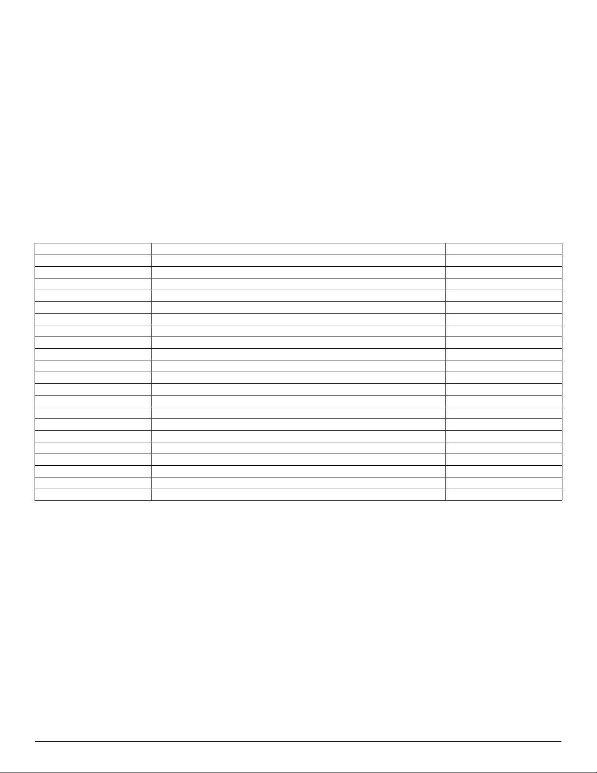
In protection or malfunction, the LED displays an error code or a protection code. The diagnostic codes displayed on the outdoor units are listed on
Table 12.
Table 12 — Outdoor Unit Error Display
OUTDOOR UNIT DISPLAY LED STATUS INDOOR UNIT DISPLAY
E0 Outdoor EEPROM malfunction F4
E2 Communication malfunction between indoor and outdoor units E1
E3 Communication malfunction between IPM board and outdoor main board — —
E4 Open or short circuit of outdoor temperature sensor (T3,T4,T5,T2B) F2/F1/F3/F6
E5 Voltage protection P1
E6 PFC module protection — —
E8 Outdoor fan speed has been out of control (only for DC fan motor models) F5
E9 Wrong wiring connection of 24K indoor unit — —
F1 No A Indoor unit coil outlet temp. sensor or connector of sensor is defective — —
F2 No B Indoor unit coil outlet temp. sensor or connector of sensor is defective — —
F3 No C Indoor unit coil outlet temp. sensor or connector of sensor is defective — —
F4 No D Indoor unit coil outlet temp. sensor or connector of sensor is defective — —
F5 No E Indoor unit coil outlet temp. sensor or connector of sensor is defective — —
F6 No F Indoor unit coil outlet temp. sensor or connector of sensor is defective — —
P0 Temperature protection of compressor top P2
P1 High pressure protection P2
P2 Low pressure protection P2
P3 Current protection of compressor F0
P4 Temperature protection of compressor discharge — —
P5 High temperature protection of condenser — —
P6 IPM module protection P0
Loading ...