Loading ...
Loading ...
Loading ...
38MGRBQ: Installation Instructions
Manufacturer reserves the right to change, at any time, specifications and designs without notice and without obligations.
15
SYSTEM VACUUM AND CHARGE
Refrigerant pipes and indoor unit coils should be evacuated using the
recommended 500 microns deep vacuum method. The alternate triple
evacuation method may be used if the following procedure is followed.
Always break a vacuum with dry nitrogen.
NOTE: All units (except the 18,000 BTU model) have a Master Suction and
Liquid Line Service Valve.
Using Vacuum Pump
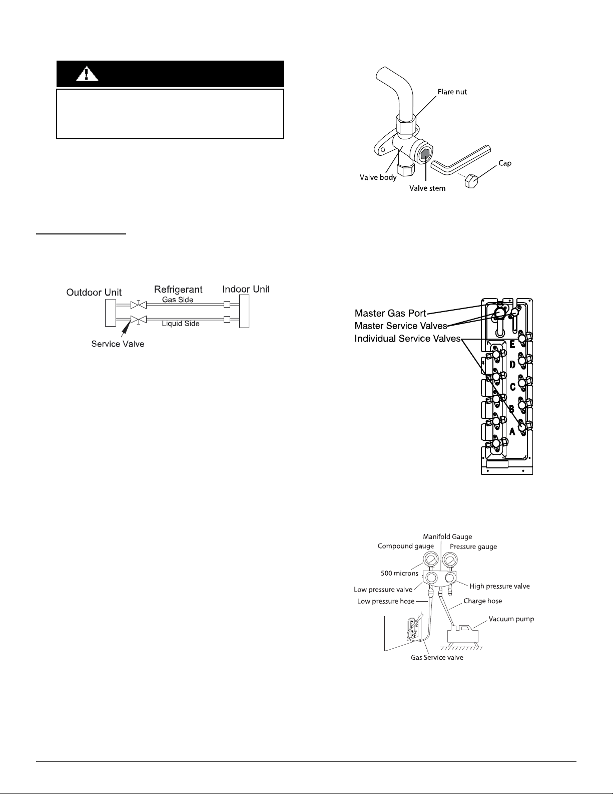
1. Completely tighten the flare nuts of the liquid and gas pipes on the
indoor and outdoor side (for all fan coils) (see Fig 22 ).
A220020
Fig. 22 —Service Valves
2. For size 18, DO NOT open the Gas or Liquid service valves until
the evacuation is complete. For sizes 24-48, fully open all the
connected individual service valves (with the line set attached). DO
NOT open the Master Service Valves until the evacuation is
complete (see Fig 23 ).
3. For size 18, connect the manifold gauge (low side hose) to the
Individual Service Valve (5/16 port, use the adapter to fit a 1/4in
hose) to evacuate each of the circuits. For sizes 24-48, connect the
manifold gauge (low side hose) to the Master service valve (5/16
port, use the adapter to fit a 1/4in. hose) to evacuate all circuits at the
same time (see Fig. 25).
4. Connect the charge hose to the vacuum pump.
5. Open (fully) the low pressure valve of the manifold gauge (see Fig.
25 for 18K. Fig. 24 for sizes 24K-48K).
6. Start the vacuum pump.
7. Evacuate using either the deep vacuum or the triple evacuation
method (see Fig. 27 and 28).
8. After the evacuation is complete, fully close the low pressure valve
of the manifold gauge and stop the vacuum pump operation.
9. Insert a hexagonal wrench into each Gas Side Service Valve for size
18 or into the Master Gas Side Service Valve for sizes 24-48 and
open the valve by turning the wrench 1/4 counterclockwise. Listen
for gas to exit the system (see Fig. 23).
A220021
Fig. 23 —Service Valve Diagram
10. Reference Table 5 on page 5 when additional charge is needed.
11. Disconnect the charge hoses and manifold gauge.
12. Using a hexagonal wrench, fully open all the gas and liquid service
valves for the size 18 and all the Master Gas and Liquid service
valves for sizes 24-48 (see Fig. 23).
A220022
Fig. 24 —Service Valves Sizes 24-48
NOTE: The Master Valve utilizes a 5/16-inch port.
A220023
Fig. 25 —Manifold Gauge
UNIT DAMAGE HAZARD
Failure to follow this caution may result in equipment damage or
improper operation.
Never use the system compressor as a vacuum pump.
CAUTION
Loading ...
Loading ...
Loading ...