[11111:
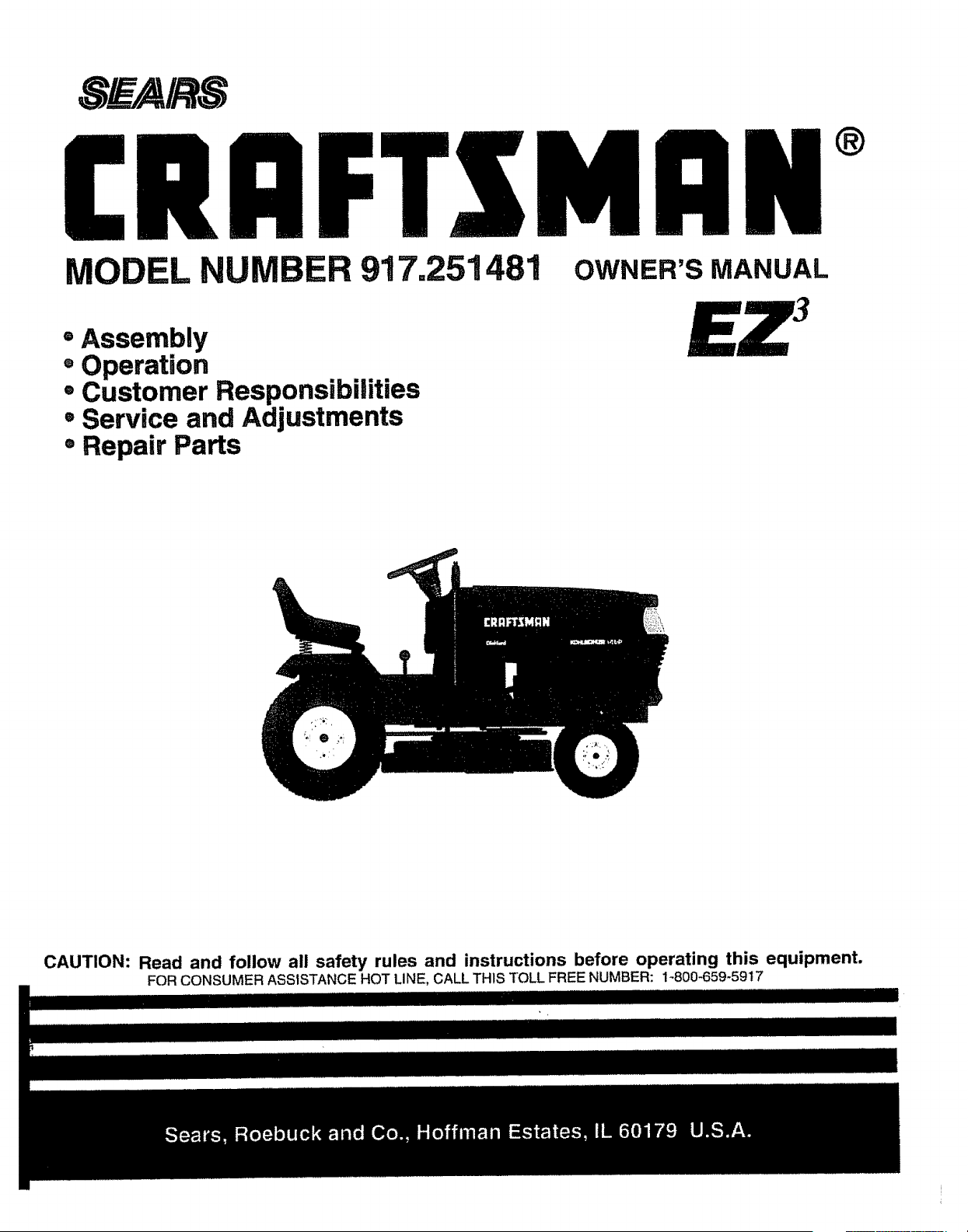
MODEL NUMBER 917.251481
OWNER'S MANUAL
®
= Assembly
, Operation
° Customer Responsibilities
° Service and Adjustments
• Repair Parts
CAUTION: Read and follow all safety rules and instructions before operating this equipment.
FOR CONSUMER ASSISTANCE HOT LINE, CALL THIS TOLL FREE NUMBER: 1_800-659-5917
SAFETY RULES
Safe Operation Practices for Ride-On Mowers
IMPORTAN'r': THIS CUTTING MACHINE IS CAPABLE OF AMPUTATING HANDS AND FEET AND THROWING OBJECTS.
FAILURE TO OBSERVE THE FOLLOWING SAFETY INSTRUCTIONS COULD RESULT IN SERIOUS INJURY OR DEATH_
I. GENERAL OPERATION
• Read, understand, and follow all instructionsin the manual
and on the machine before starting
,, Only allow responsible adults, who are familiar with the
instructions,to operate the machine.
. Clear the area of objects such as rocks, toys, wire, etc..,
which could be picked up and thrown by the blade_
• Be sure the area isclear ofother people before mowing_ Stop
machine if anyone enters the area.
• Never carry passengers.,
• Do notmow in reverse unless absolutelynecessary. Always
look down and behind before and while backing.
° Be aware of the mower discharge directionand do not point
it at anyone. Do not operate the mower withouteither the
entire grass catcher or the guard in place,
o Slow down before turning.
. Never leave a runningmachine unattended_ Always turn off
blades, set parking brake, stop engine, and remove keys
before dismounting
. Turn off blades when not mowing.
, Stop engine before removing grass catcher or unclogging
chute.
• Mow only in daylight or good artificial light
• Do not operate the machine while under the influence of
alcohol or drugs
• Watch for traffic when operating near or crossing roadways
• Use extra care when loading or unloading the machine into
a trailer or truck
II. SLOPE OPERATION
Slopes are a major factor related to loss-of-control and tipover
accidents, which can result insevere injury or death All slopes
require extra caution If youcannot back up the slope or if you feel
uneasy on it, do not mow it
DO:
= Mow up and down slopes, not across
• Remove obstacles such as rocks, tree limbs, etc,
° Watch for holes, ruts, or bumps Uneven terrain could
overturn the machine Tall grass can hide obstacles
° Use slow speed Choose a low gear so that youwil! not have
to stop or shift while on the slope
° Follow the manufacturer's recommendations for wheel
weights or counterweights to improve stability
° Use extra care with grass catchers or other attachments
These can change the stability of the machine°
° Keep all movement on the slopes slowand gradual Do not
make sudden changes in speed or direction
° Avoid starting or stopping on a slope tf tires lose traction,
disengage the blades and proceed slowly straight down the
slope.
DO NOT.'
• Donot turnon slopes unless necessary, and then,turnslowly
and gradually downhill, if possible.
• Do not mow near drop-offs,ditches, or embankments. The
mower could suddenly turn over if a wheel is over the edge
of a cliff or ditch, or if an edge caves in,
= Do not mow on wet grass. Reduced traction could cause
sliding.
. Do not tryto stabilize the machine byputting yourfoot on the
ground.
• Do not use grass catcher on steep slopes.
2
Ul. CHILDREN
Tragic accidents can occur if the operator is not alert to the
presence of children_Children are often attracted to the machine
and the mowing activity. Neverassume that children will remain
where you last saw them.
Keep chitdrenout of the mowing area and underthe watchful
care of another responsible adulto
• Be alert and tum machine off if children enter the area
• Before and when backing, look behind and down for small
children
• Never carry children They may fall off and be seriously
injured or interfere with safe machine operation
• Never allow children to operate the machine
• Use extra care when approaching blind corners, shrubs,
trees, or other objects that may obscure vision°
IV. SERVICE
, Use extra care in handling gasoline and other fuels They are
flammable and vapors are explosive
Use only an approved container
Never remove gas cap or add fuel with the engine
running Allow engine to cool before refueling Do not
smoke
Never refuel the machine indoors
Never store the machine or fuel container inside where
there is an open flame, such as a water heater
* Never run a machine inside a closed area
• Keep nuts and bolts, especially blade attachment bolts tight
and keep equipment in good condition
, Never tamper with safety devices Check their proper
operation regularly
• Keep machine free of grass, leaves, or other debris build-up
Clean oil or fuel spillage Allow machine to cool before
storing
• Stop and inspect the equipment if you strike an object
Repair, if necessary, before restarting
• Never make adjustments or repairs with the engine iunning
• Grasscatchercomponents aresubjecttowear damage, and
deterioration, which could expose moving parts or allow
objects to be thrown Frequently check components and
replace with manufacturer's recommended parts, when nec-
essary
. Mower blades are sharp and can cut.. Wrap the blade(s) or
wear gloves, and use extra caution when servicing them
• Check brake operation frequently. Adjust and service as
required.
Look for this symbol to point out Important
safety precautions. It means
CAUTIONI[t BECOME ALERTIII YOUR
SAFETY IS INVOLVED.
/ /
Hl=l=l,,uw/,,=Lw,,/==
CAUTION; Always disconnect spark plug
wire and place wire where it cannot contact
spark plug in order to prevent accidental
starting when setting up, transporting,
adjusting or making repairs.
......... ........ .................... i ii ii-iii
A WARNING A
The engine exhaust from this product con-
tains chemicals known to the State of Califor-
nia to cause cancer, birth defects, or other
reproductive harm.
CONGRATULATIONS on your purchase of a Sears
Tractor° It has been designed, engineered and manufac-
tured to give you the best possible dependability and
performance,.
Should you experience any problem you cannot easily
remedy, please contact your nearest Sears Authorized
Service Center/Departmento We have competent, well-
trained technicians and the proper tools to service or repair
this tractor.
Please read and retain this manual The instructionswill
enabre you to assemble and maintain your tractor properly.
Always observe the "SAFETY RULES"°
MODEL
NUMBER 917.251481
SERIAL
NUMBER
DATE OF PURCHASE
THE MODEL AND SERIAL NUMBERS WILL BE FOUND
ON A PLATE UNDER THE SEAT.
YOU SHOULD RECORD BOTH SERIAL NUMBER AND
DATE OF PURCHASE AND KEEP IN A SAFE PLACE
FOR FUTURE REFERENCE°
MAINTENANCE AGREEMENT
A Sears Maintenance Agreement is avaitable on this prod-
uct. Contact your nearest Sears store for details.
CUSTOMER RESPONSIBILITIES
• Read and observe th e safety nJles.
• Follow a regularschedule in maintaining, caring for and
using your tractor_
. Follow the instructions under"Customer Responsibili-
ties" and "Storage" sections of this owner s manual,.
WARNING: This tractor is equipped with an internal
combustion engine and should not be used on or near any
unimproved foresFcovered, brush-covered or grass-cov-
ered land unless the engine's exhaust system is equipped
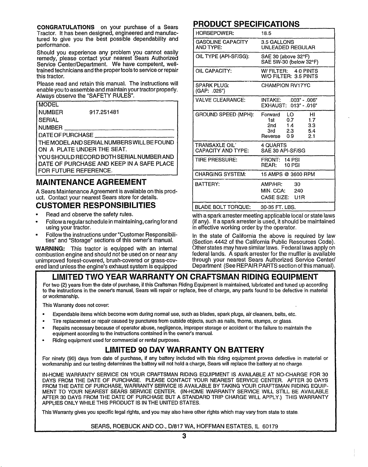
PRODUCT SPECIFICATIONS
HORSEPOWER: 18_5
GASOLINE CAPACITY 3,5 GALLONS
AND TYPE: UNLEADED REGULAR
OIL TYPE (APt-SF!SG): SAE 30 (above 32°F)
SAE 5W-30 (below 32°F)
OIL CAPACITY: Wl FILTER: 40 PINTS
W/O FILTER: 3.,5 PINTS
SPARK PLUG: CHAMPION RV17YC
(GAP: _025")
VALVE CLEARANCE: INTAKE: .003" - °006"
EXHAUST: 013" - o016"
GROUND SPEED (MPH): Forward LO HI
1st 0_7 1.7
2nd 1.4 3,.3
3rd 2°3 5.4
Reverse 0.9 2_1
TRANSAXLE OIL' 4 QUARTS
CAPACITY AND TYPE: SAE 30 API-SF/SG
TIRE PRESSURE: FRONT: i4 PSi
REAR: 10 PSi
CHARGING SYSTEM: 15 AMPS @ 3600 RPM
BATTERY: AMP/HR: 30
MIN CCA: 240
CASE SIZE: U1R
BLADE BOLT TORQUE: 30-35 FT. LBS.
with a spark arrester meeting applicable Iocal or state laws
(if any). If a spark arrester is used, it should be maintained
in effective working order by the operator.,
In the state of California the above is required by law
(Section 4442 of the California Public Resources Code),.
Other states may have similar laws. Federal laws apply on
federal lands° A spark arrester for the muffler is available
through your nearest Sears Authorized Service Center/
Department (See REPAIR PARTS section of this manual).
LIMITED TWO YEAR WARRANTY ON CRAFTSMAN RIDING EQUIPMENT
For two (2) years from the date of purchase, if thisCraftsman Riding Equipment is maintained, lubricated and tuned up according
to the instructions in the owner's manual, Sears wilt repair or replace, free of charge, any parts found to be defective in material
or workmanship.
This Warrant,./does not cover;
° Expendable items which become wom during normal use, such as blades, spark plugs, air cleaners, beJts, etc.
° Tire replacement or repair caused by puncturesfrom outsideobjects, such as nails, thorns, stumps, or glass.
• Repairs necessary because of operator abuse, negligence, improper storage or accident or the failure to maintain the
equipment according to the instructionscontained inthe owner's manual.
• Riding equipment used for commercial or rental purposes.
LIMITED 90 DAY W'ARRANTY ON BATTERY
For ninety (90) days from date of purchase, if any battery included with this riding equipment proves defective in matedal or
workmanship and our testing determines the battery will not hold a charge, Sears will replace the battery at no charge_
IN*HOME WARRANTY SERVICE ON YOUR CRAFTSMAN RIDING EQUIPMENT IS AVAILABLE AT NO-CHARGE FOR 30
DAYS FROM THE DATE OF PURCHASE° PLEASE CONTACT YOUR NEAREST SERVICE CENTER,. AFTER 30 DAYS
FROM THE DATE OF PURCHASE, WARRANTY SERVICE IS AVAILABLE BY TAKING YOUR CRAFTSMAN RIDING EQUIP-
MENT TO YOUR NEAREST SEARS SERVICE CENTER, (IN-HOME WARRANTY SERVICE WILL S_ILL BE AVAILABLE
AFTER 30 DAYS FROM THE DATE OF PURCHASE BUT A STANDARD TR1P CHARGE WtLL APPLY.) THIS WARRANTY
APPUES ONLY WHILE THIS PRODUCT IS IN THE UNITED STATES.
This Warranty gives you specific legal rights, and you may also have other rightswhich may vary from state to state,
SEARS, ROEBUCK AND CO. 1:)/817 WA, HOFFMAN ESTATES, IL 60179
3
ii Li iill iill
TA
........................ HI,,,,
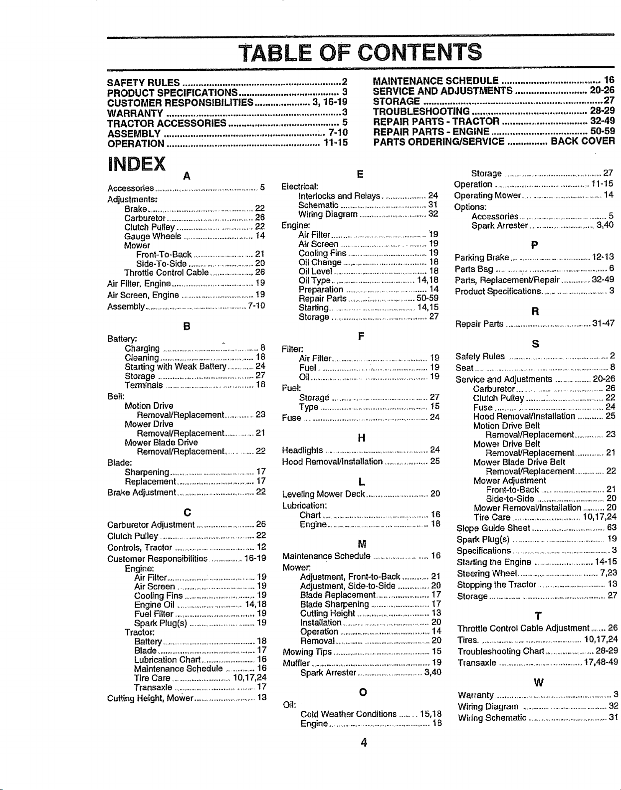
SAFETY RULES ............................................................ 2
PRODUCT SPECIFICATIONS ...................................... 3
CUSTOMER RESPONSIBILITIES ..................... 3, t6-19
WARRANTY ..................................................................3
TRACTOR ACCESSORIES ..........................................5
ASSEMBLY .......................................................... :,. 7-10
OPERATION .......................................................... 11-15
CONTENTS
.................. .......... i,
MAINTENANCE SCHEDULE ..................................... 16
SERVICE AND ADJUSTMENTS ........................... 20-26
STORAGE ................................................................... 27
TROUBLESHOOTING ........................................... 28-29
REPAIR PARTS - TRACTOR ................................ 32-49
REPAIR PARTS - ENGINE .................................... 50-59
PARTS ORDERING/SERVICE ............... BACK COVER
iNDEX
A
Accessories......................................................5
Adjustments:
Brake ....................................................22
Carburetor ............................................26
Clutch Pulley ...........................................22
Gauge Wheels .......................................14
Mower
Front-To-Back ...............................21
Side-TooSide ................................20
Throttle Control Cable .................. 26
Air Filter, Engine ..................................... 19
Air Screen, Engine .....................................19
Assembly .............................................................7-10
B
Battery:
Charging .......................... _ ...................8
Cteaning ..............................................18
Starting with Weak Battery ................24
Storage ...............................................27
Terminals .................................................18
Belt:
Motion Drive
RemovaitReplacement ...................23
Mower Drive
Removal/Replacement .................21
Mower Blade Drive
RemovallReplacement ................22
Blade:
Sharpening .................................................17
Replacement .......................................17
Brake Adjustment .......................................22
C
Carburetor Adjustment ...............................26
Clutch Pulley ......................................................22
Controls, Tractor ........................................12
Customer Responsibilities ..................16-19
Engine:
Air Filter.............................................i9
Air Screen ............................................19
Cooling Fins ...................................19
Engine Oil ..........................................14,18
Fuel Filter .................................... 19
Spark Plug(s) .......................................19
Tractor:
Battery ...................................................18
Blade .............................................17
Lubrication Chart ....................... 16
Maintenance Schedule ............ 16
Tire Care ..............................10,17,24
Transaxle .............................................17
Cutting Height, Mower ................................13
E
Electrical:
Interlocks and Relays .......................24
Schematic ..............................................31
Wiring Diagram .................................32
Engine:
Air Filter.....................................................t9
AirScreen .....................................................19
Cooling Fins ...........................................19
Oil Change .......................................18
Oil Level ..............................................18
Oil Type ..........................................14,18
Preparation ..........................................14
Repair Pads ..........:........................50-59
Starling .............................................14,15
Storage ..................................................27
F
Filter:
Air Filter........................................................19
Fuel .........................._.............................19
Oil ..............................................................19
Fuel:
Storage .......................................................27
Type ....................................................t5
Fuse
.........................................................
24
H
Headlights .................................................................24
Hood Removal/Installation .......................25
L
Leveling Mower Deck ...............................20
Lubrication:
Chad .....................................................16
Engine .............................................._............t8
M
Maintenance Schedule ................................16
Mower:.
Adjustment, Front-to-Back ............ 2t
Adjustment, Side-to.Side ...............20
Blade Replacement .........................17
Blade Sharpening .............................t7
Cutting Height ..................................13
installation ......................................................20
Operation ........................................ 14
Removal ....................................................20
Mowing Tips ..................................................15
Muffler .........................................................t9
Spark Attester .................................3,40
O
Oil: '
Cold Weather Conditions ......... 15,18
Engine .......................................................t8
Storage ..................................................27
Operation ...............................................11-15
Operating Mower ..............................................14
Options:
Accessories ..................................................5
Spark Arrester ................................3,40
P
Parking Blake .......................................12-13
Parts Bag ........................................................6
Parts, Replacemen'dRepair ..................32-49
Product Specifications ........................................3
R
Repair Pads ........................................31-47
S
Safety Rules ...................................................2
Seat ......................................................................................8
Service and Adjustments ................ 20-26
Carburetor .......................................................26
Clutch Pulley .........:......................... 22
Fuse ................L..........................................24
Hood Removal/Installation ............ 25
Motion Drive Belt
Removal/Replacement ...............23
Mower Drive Belt
Removal/Replacement ............. 21
Mower Blade Drive Belt
RemovalfReplacement ............ 22
Mower Adjustment
Front-to-Back .................................21
Side-to-Side ..................................20
Mower Removal/Installation ..........20
Tire Care ..................................10,17,24
Slope Guide Sheet ...................................63
Spark Plug(s) ..............................................................t9
Specifications ......................................................3
Starling the Engine ............................14-15
Steering Wheel .......................................7,23
Stopping the Tractor ........................................13
Storage ......... ............................................. 27
T
Throttle Control Cable Adjustment ....... 26
Tires ...............................................................10,17,24
Troubleshooting Chart ...........................28-29
Transaxle ..........................................t7,48-49
W
Warranty ..........................................................3
Wiring Diagram ..................................................32
Wiring Schematic ................................. 31
4
AND ATTACHMENTS
._ ................. ii i,,: ..........................................
These accessories and attachments were available through most Sears retail outlets and service centers when the tractor was purchased,.
Most Sears stores can order these items for you when you provide the model number of your tractor,
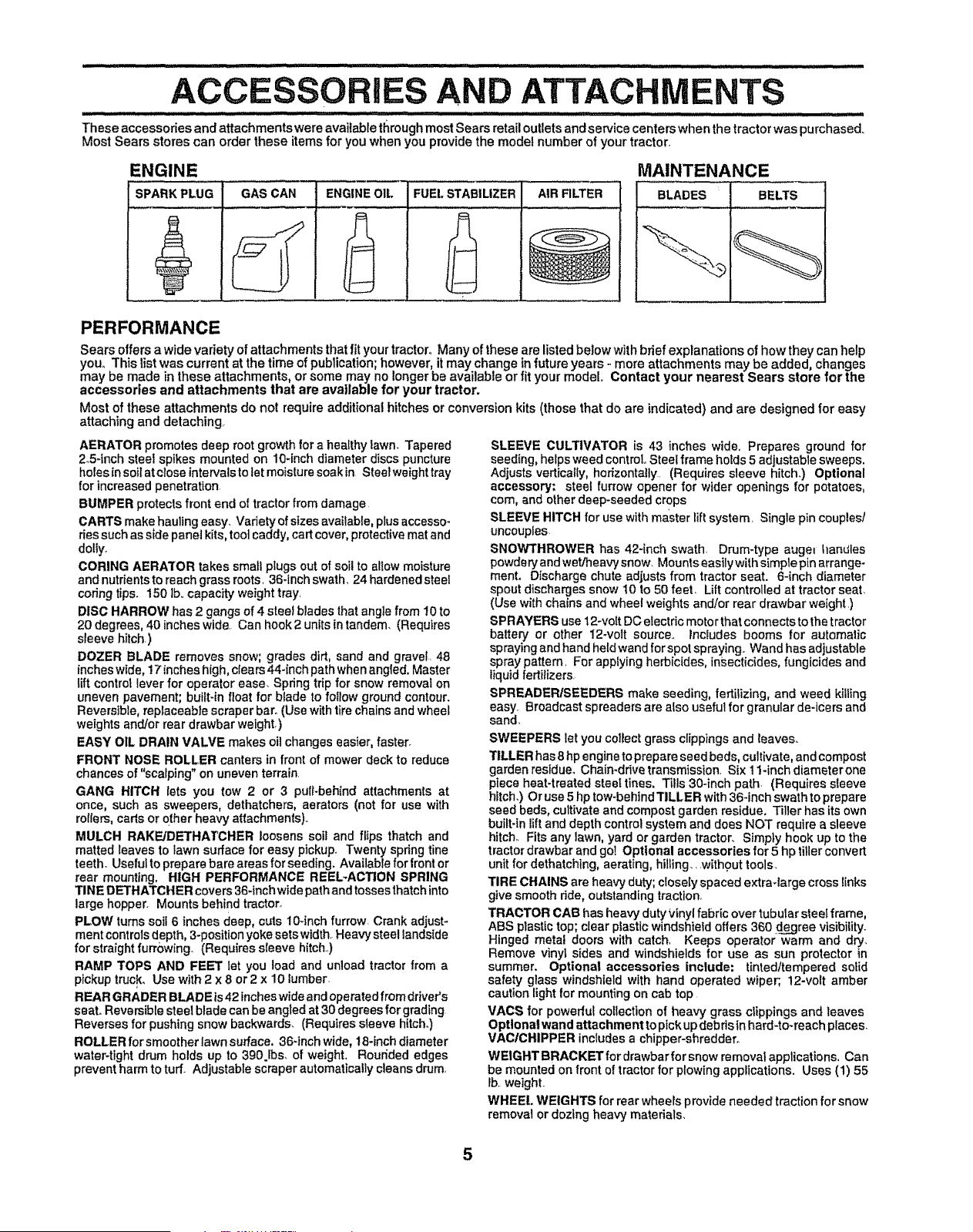
ENGINE MAINTENANCE
SPARK PLUG I BLADES BELTS
t'
I
GAS CAN ENGINE OIL FUEL STABlUZER AIR FILTER
PERFORMANCE
Sears offersa wide variety of attachments that fityour tractor° Many of these are listed below with brief explanations of how they can help
your This list was current at the time of publication;however, it may change infuture years - more attachments may be added, changes
may be made in these attachments, or some may no longer be available or fit your model, Contact your nearest Seers store for the
accessories and attachments that are available for your tractor.
Most of these attachments do not require additional hitches or conversion kits (those that do are indicated) and are designed for easy
attaching and detaching,
AERATOR promotes deep root growth for a healthy lawn. Tapered
2.54nch steel spikes mounted on 10-inch diameter discs puncture
holes in soil at cTose intervals to tet moisture soak in Steelweight tray
for increased penetration
BUMPER protects front end of tractor from damage
CARTS make hauling easy. Variety of sizes available, plus accesso-
ries such as slde panet kits, tool caddy, cart cover, protective mat and
dolly,
GORING AERATOR takes small plugs out of soil to allow moisture
and nutrients to reach grass roots, 36-1nch swath+ 24 hardened steel
coring tips. 150 lb,. capacity weight troy.
DISC HARROW has 2 gangs of 4 steel blades that angle from i0 to
20 degrees, 40 inches wide. Can hook 2 units in tandem. (Requires
sleeve hitch.)
DOZER BLADE removes snow; grades dirt, sand and gravel, 48
inches wide, 17 inches high, clears 44+inch path when ang{ed, Master
lift control lever for operator ease. Spring trip for snow removal on
uneven pavement; built-in float for blade to follow ground contour.
Reversible, replaceable scraper bar+ (Use with tire chafns and wheel
weights and/or rear drawbar weight.)
EASY OIL DRAIN VALVE makes oil changes easier, faster.
FRONT NOSE ROLLER canters in front of mower deck to reduce
chances of "scalping" on uneven terrain
GANG HITCH lets you tow 2 or 3 pulFbeh{nd attachments at
once, such as sweepers, dethatchers, aerators (not for use with
rollers, carts or other heavy attachments).
MULCH RAKE!DE'THATCHER loosens soil and flips thatch and
matted leaves to lawn surface for easy pickup. Twenty spring tine
teeth. Useful to prepare bare areas for seeding, Available for front or
rear mounting. HIGH PERFORMANCE REEL-ACTION SPRING
TINE DETHATCHER covers 36-inch wide path and tosses thatch into
large hopper. Mounts behind tractor.
PLOW turns soil 6 inches deep, cuts 10+inch furrow. Crank adjust-
ment controls depth, 3-position yoke sets width. Heavy steel lands{de
for straight furrowing.. (Requires sleeve hitch.)
RAMP TOPS AND FEET let you load and unload tractor from a
pickup truck. Use with 2 x 8 or 2 x 10 lumber
REAR GRADER BLADE is 42 inches wide and operated from driver's
seat.. Reversible steel blade can be angled at 30 degrees for grading
Reverses for pushing snow backwards. (Requires sleeve hitch+)
ROLLER forsmoother lawn surface, 36-inch wide, 18-inch diameter
water-tight drum holds up to 390.lbs+ of weight, Roudded edges
prevent harm to turf. Adjustable scraper automatically cleans drum,
SLEEVE CULTIVATOR is 43 inches wide, Prepares ground for
seed{ng, helps weed control Steel frame holds 5 adjustable sweeps.
Adjusts vertically, horizontally (Requires sleeve hitch.) Optional
accessory: steel furrow opener for wider openings for potatoes,
corn, and other deep-seeded crops
SLEEVE HITCH for use with master lift system. Single pin couples/
uncouples
SNOWTHROWER has 42-inch swath. Dram-type auge_ IlanLfles
powdery and wet/heavy snow. Mounts easily with simple pin arrange-
ment. Discharge chute adjusts from tractor seat. 6-inch diameter
spout discharges snow 10 to 50 feet. Lift controlled at tractor seat.
(Use with chains and wheel weights and/or rear drawbar weight )
SPRAYERS use 12-volt DC electric motor that connects to the tractor
battery or other 12welt source., includes booms for automatic
spraying and hand held wand for spot spraying.. Wand has adjustable
spray pattern. For applying herbicides, insecticides, fungicides and
liquid fertilizers.
SPREADER/SEEDERS make seeding, fertilizing, and weed killing
easy Broadcast spreaders are also usefut for granular de-icers and
sand,
SWEEPERS let you collect grass clippings and leaves.
TILLER has 8 hp engine to prepare seed beds, cultivate, and compost
garden residue, Chain.drive transmission. Six t 1-inch diameter one
piece heat-treated steer tines. Tills 30-inch path. (Requires s{eeva
hitch.) Or use 5 hp tow-behtndTiLLER with 36-inch swath to prepare
seed beds, cultivate and compost garden residue, Tiller has its own
built-in lift and depth control system and does NOT require a sleeve
hitch° Fits any lawn, yard or garden tractor. Simply hook up to the
tractor drawbar and got Optional accessories for 5 hp tiller convert
unit for dethatchlng, aerating, hilling., without tools.
TIRE CHAINS are heavy duty; closely spaced extra4arge cross links
give smooth ride, outstanding traction,
TRACTOR CAB has heavy duty Vinyl fabric over tubular steef frame,
ABS plastic top; clear plastic windshield offers 360 de3ree visibility.
Hinged metal doors with catch, Keeps operator warm and dry.
Remove vinyl sides and windshields for use as sun protector in
summer. Optional accessories include: tinted/tempered solid
safety glass windshield with hand operated wiper;, 12-vort amber
caution light for mounting on cab top
VACS for powerful collection of heavy grass clippings and leaves
Optlonat wand attachment to pick up debris in hard-to+reach places.
VAC/CHIPPER includes a chipper-shredder.
WEIGHT BRACKET for drawbar for snow removal applications, Can
be mounted on front of tractor for plowing applications. Uses (1) 55
lb. weight.
WHEEL WEIGHTS for rear wheels provide needed traction for snow
removal or dozlng heavy materials.
5
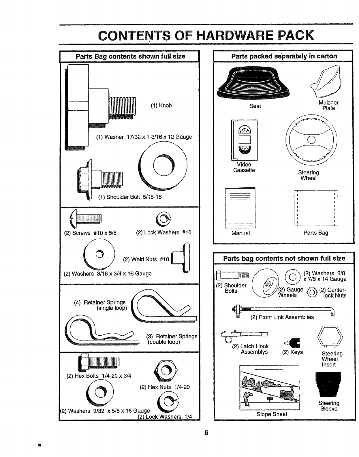
Parts Bag contents shown full size
i
CONTENTS OF HARDWARE PACK
I
I
I
I
t
(1) Knob
(1) Washer 17/32 x 1-3/16 x 12 Gauge
(1) Shoulder Bolt 5/164 8
(2) Screws #!0 x 5/8
@
@
(2) Lock Washers #t0
(2) Weld Nuts #10 _ l
"=3J
(2) Washers 3/16 x 3/4 x 16 Gauge
(4) Retainer Springs _f//'__\ .
(single loop)
__ (3) Retainer Springs
= (double loop)
(2) Hex Bolts 1/4-20 x 3/4
(2) Hex Nuts 1/4-20
12)Washers 9/32 x 5/8 x 16 Gauge
.....................' (2) Lo,ckWashers 1/4
Video
Cassette
Steering
Wheel
Manual
I ,
I
Parts Bag
Parts bag contents not shown full size
_ _ (2)Washers 3/8
(2) Shou,der (/_) ___...// x 7i8x14Gauge
Bolts \ _///(2) Gauge _ (2) Center-
Wheels _ lock Nuts
_=="(2) Front Link Assemblies
(2) Latch Hook
Assemblys (2) Keys
Steering
Wheel
Insert
Slope Sheet
Steering
Sleeve
6
LY
Your new tractor has been assembled at the factor/with the exception of those parts left unassembled for shipping purposes.,
To ensu re safe and proper operation of your tractor all parts and hardware you assemble must be tightened securely, Use
the correct tools as necessary to insure proper tightness.
TOOLS REQUIRED FOR ASSEMBLY
A socket wrench set wil! make assemblyeasier. Standard
wrench sizes are listed,
(2) 7/16" wrenches Tire pressure gauge
(1) 1/2" wrench Utility knife
(1) 9/16" wrench
(1) 3/4" socket with drive ratchet
When right or left hand is mentioned in this manual, it
means when you are in the operating position (seated
behind the steering wheel),
TO REMOVE TRACTOR FROM CARTON
UNPACK CARTON
- Remove all accessible loose parts and parts cartons
from carton (See page 6)°
. Cut, from top to bottom, along 1ineson all four corners
of carton, and lay panels flat,,
• Remove mower and packing materials.
° Check for any additional loose parts or cartons and
remove,
BEFORE ROLLING TRACTOR OFF SKID
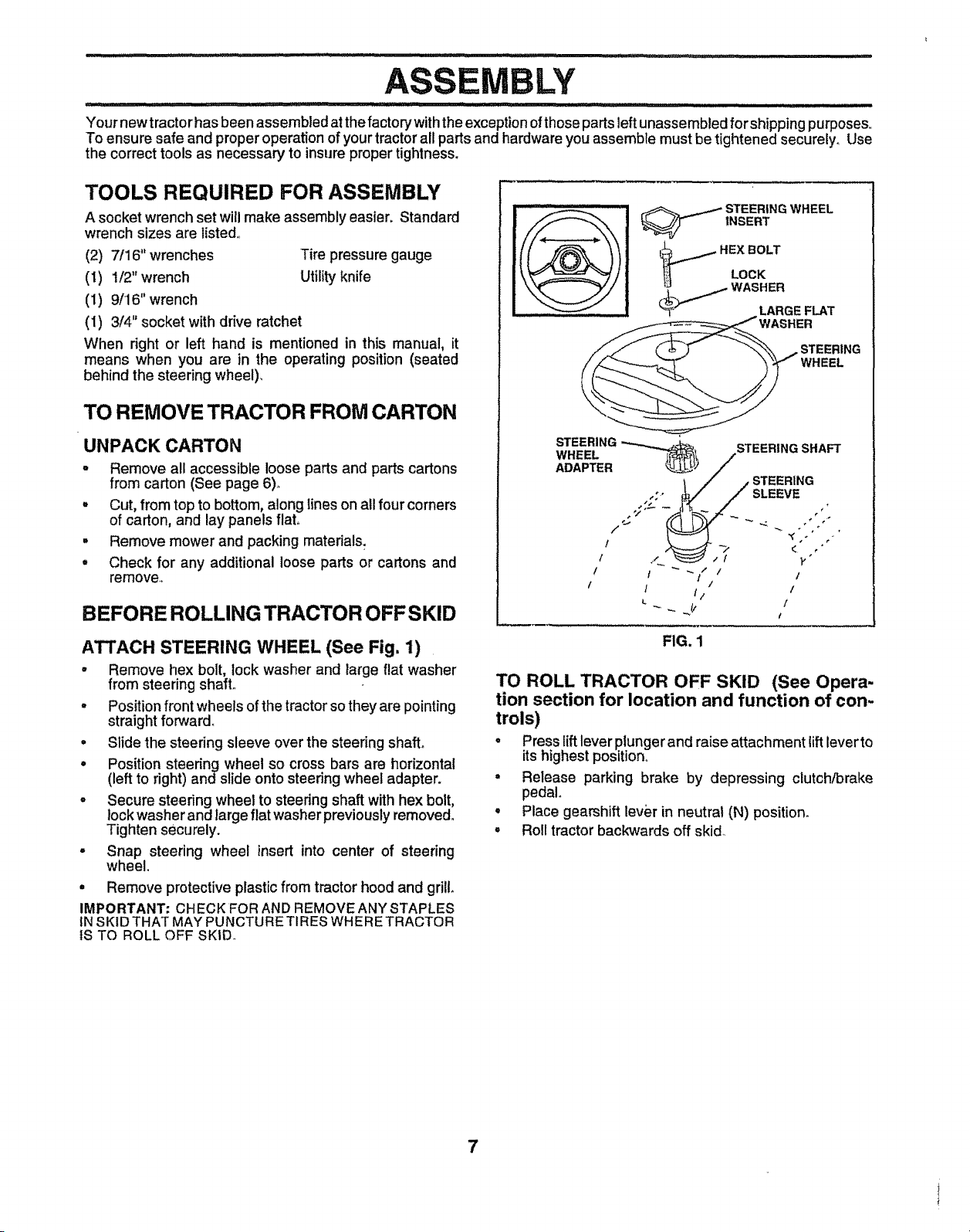
ATTACH STEERING WHEEL (See Fig. 1)
° Remove hex bolt, lock washer and large flat washer
from steering shaft°
° Positionfront wheels of the tractorsothey are pointing
straight forward°
• Slide the steering sleeve over the steering shaft°
. Position steering wheel so cross bars are horizontal
(left to right) and slide onto steeringwheel adapter.
• Secure steering wheel to steering shaft with hex bolt,
lock washer and large flat washer previously removed,,
Tighten securely.
- Snap steering wheel insert into center of steering
wheel.
. Remove protective plastic from tractor hood and grill
IMPORTANT: CHECK FOR AND REMOVE ANY STAPLES
tN SKID THAT MAY PUNCTURE TIRES WHERE TRACTOR
IS TO ROLL OFF SKID.
_ STEERING WHEEL
INSERT
HEX BOLT
Lock
. -.- WASHER
_I_,_ LARGE FLAT
},
! I _/ /
/ I
I I ii / I
L
FIG. 1
TO ROLL TRACTOR OFF SKID (See Opera-
tion section for location and function of con-
trols)
• Press lift lever plunger and raise attachment liftleverto
its highest position,,
• Release parking brake by depressing clutch/brake
pedal
• Place gearshift lever in neutrat (N) position.
° Roll tractor backwards off skid
7
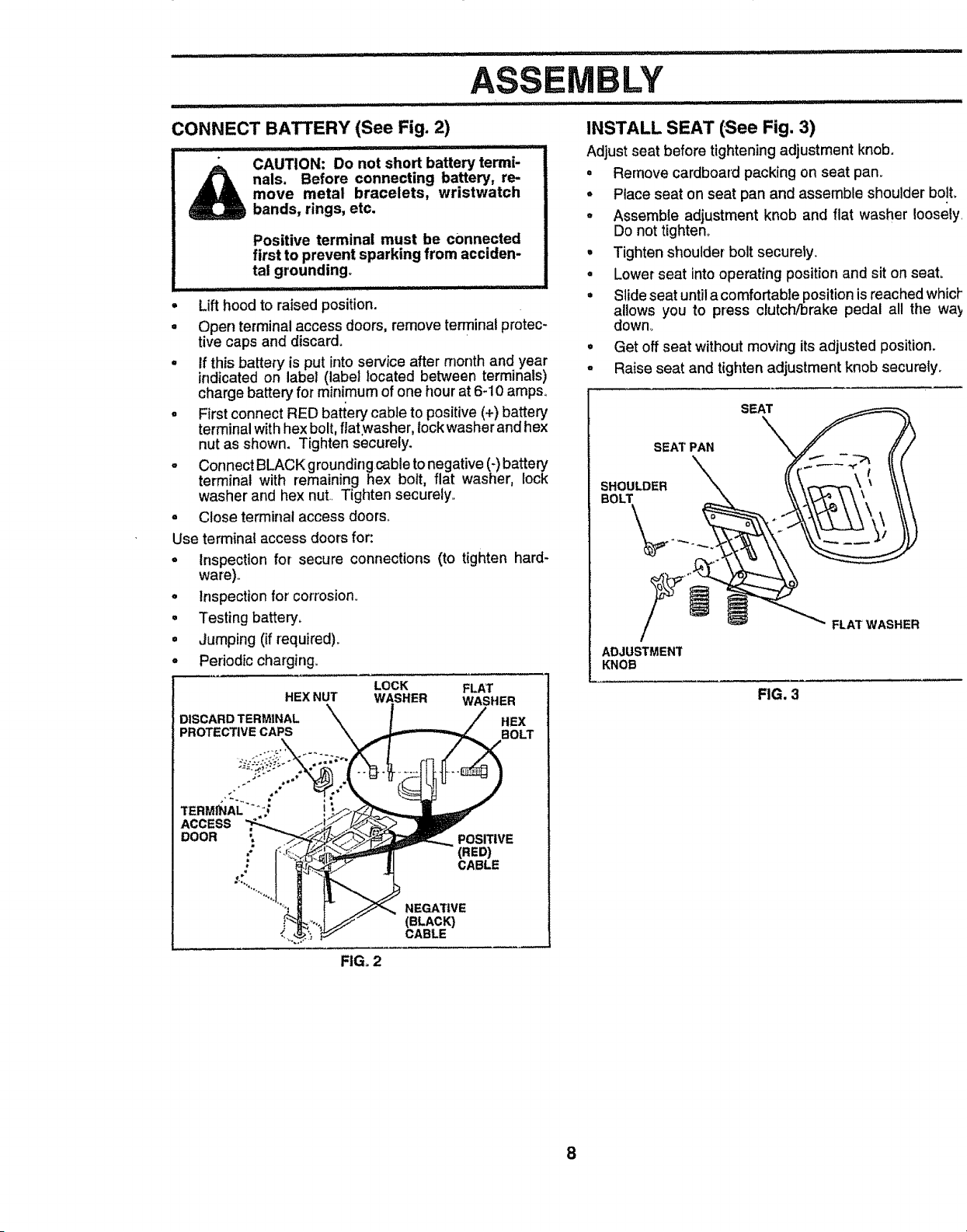
CONNECT BATTERY (See Fig. 2)
i ii .......... illl i ii,lll
CAUTION: Do not short battery termi-
_ rials. Before connecting battery, re-
move metal bracelets, wristwatch
bands, rings, etc.
Positive terminal must be connected
first to prevent sparking from acciden-
tal grounding,
...... i Illll I illlllUll illl illlll
= Lifthood to raised position.
• Open terminal access doors, remove termina! protec-
tive caps and discard.
o If this battery is put into service after month and year
indicated on label (label located between terminals)
charge battery for minimum of one hour at 6-10 amps,
, First connect RED battery cable to positive (+) battery
terminal with hex bo t, flatwasher, lock washer and hex
nut as shown. Tighten securely.
° Connect BLACK grounding cable to negative (-)battery
terminal with remaining hex bolt, flat washer, lock
washer and hex nut. Tighten securely..
o Close terminal access doors.
Use terminal access doors for:
o Inspection for secure connections (to tighten hard-
ware)..
° Inspection for corrosion_
• Testing battery.
° Jumping (if required)_
° Periodic charging.
HEX NUT
DISCARD TERMINAL
:_ROTECTIVE CAPS
LOCK FLAT
WASHER WASHER
• . / HEX
BOLT
ro.sjTIvE
(RED)
CABLE
NEGA71VE
(BLACK)
CABLE
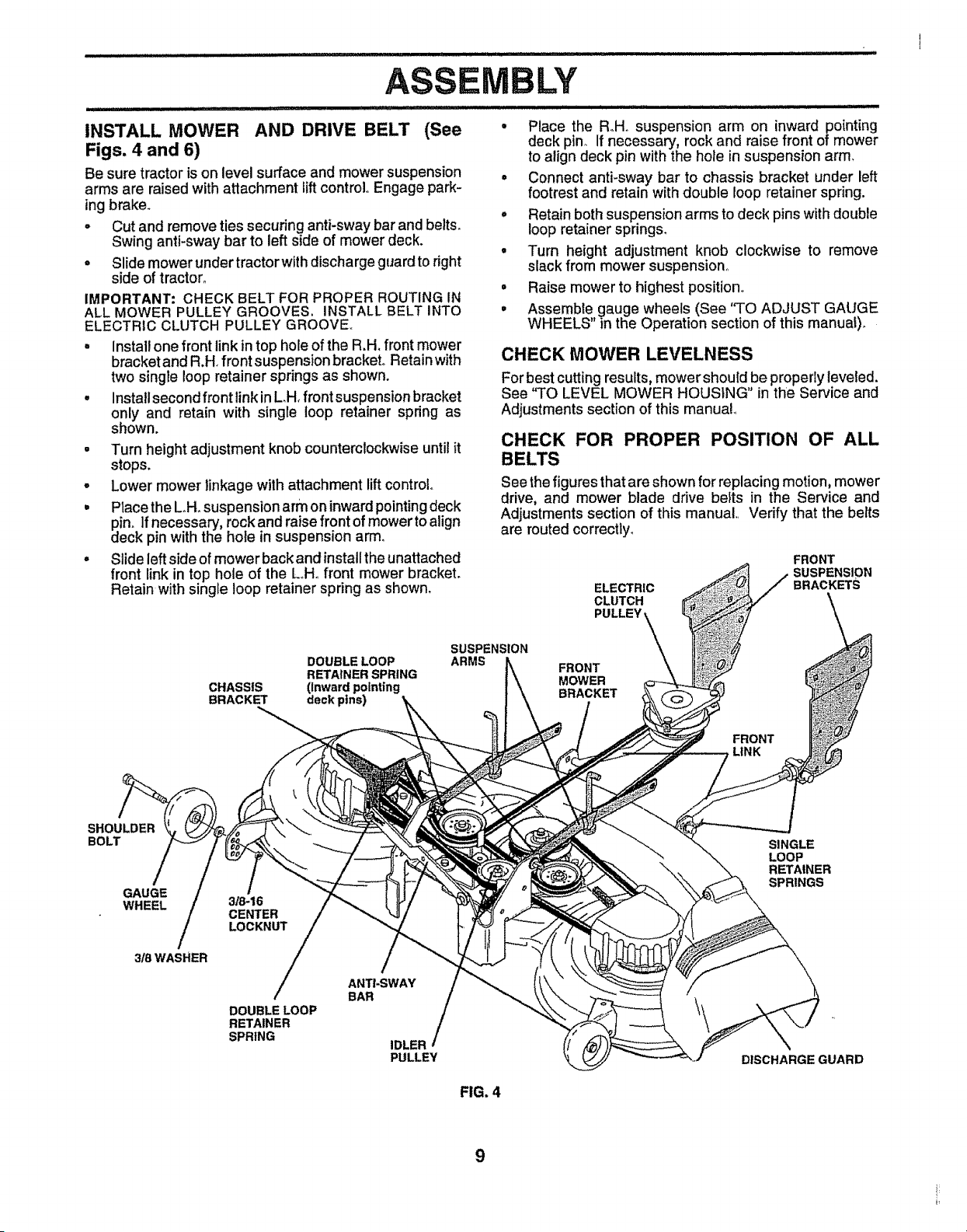
INSTALL SEAT (.See Fig. 3)
Adjustseat before tightening adjustment knob.
° Remove cardboard packing on seat pan,
o Place seat on seat pan and assemble shoulder bolt,
° Assemble adjustment knob and flat washer loosely
Do not tighten.
• Tighten shoulderbolt securely.
• Lower seat into operating position and sit on seat
• Slideseat untila comfortable positionisreached which
aUows you to press clutch/brake pedal all the wa_
down°
° Get off seat withoutmoving its adjusted position.
° Raise seat and tighten adjustment knob securely.
SEAT PAN
SHOULDER
BOLT
ADJUSTMENT
KNOB
SEAT
FLAT WASHER
FIG. 3
FIGo2
8
LY
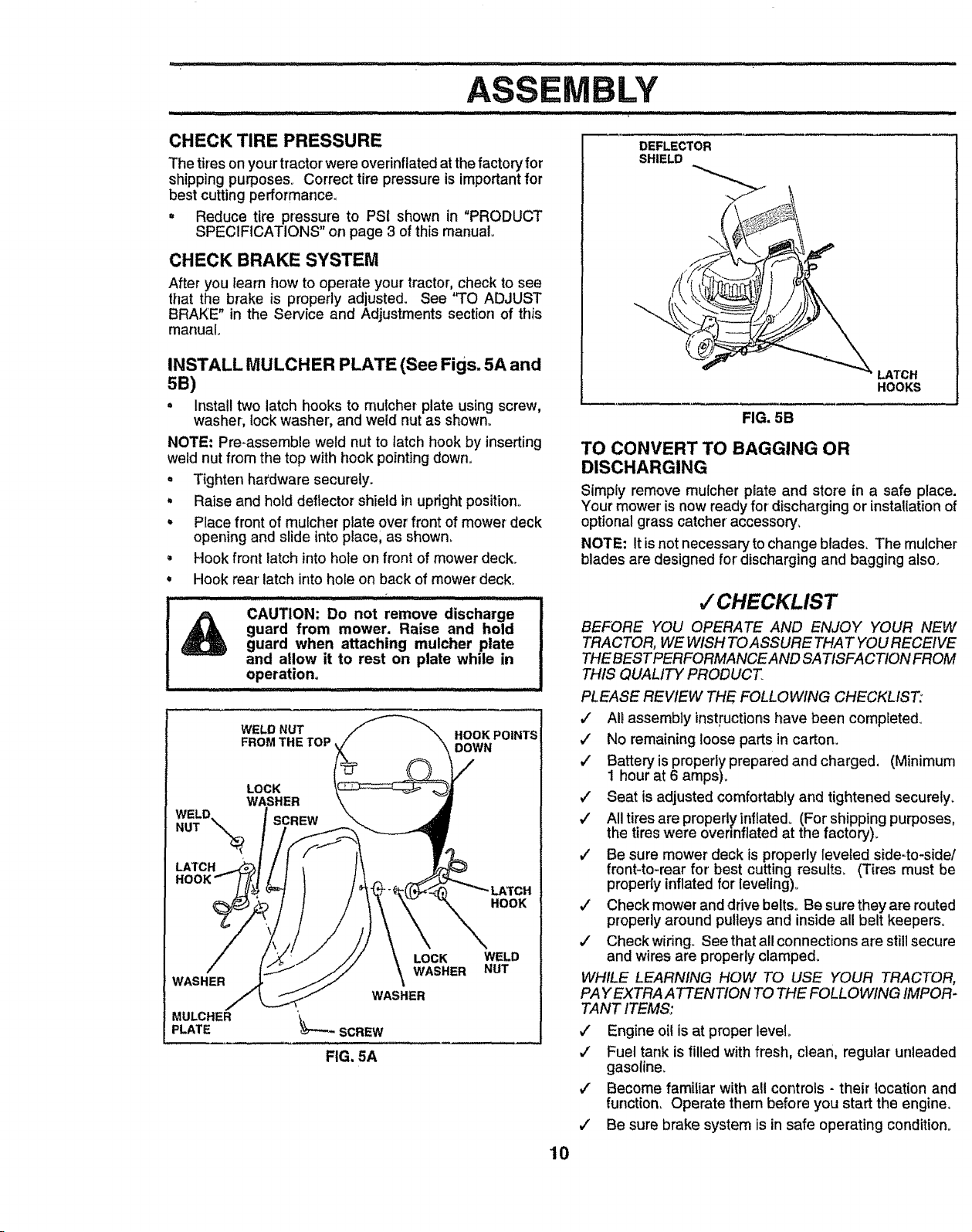
INSTALL MOWER AND DRIVE BELT (See
Figs. 4 and 6)
Be sure tractor is on level surface and mower suspension
arms are raised with attachment lift control,,Engage park-
ing brake.
• Cut and remove ties securing anti-swaybar and belts.
Swing anti-sway bar to left side of mower deck.
o Slide mower under tractorwith dischargeguardto right
side of tractor_
IMPORTANT: CHECK BELT FOR PROPER ROUTING IN
ALL MOWER PULLEY GROOVES. INSTALL BELT INTO
ELECTRZC CLUTCH PULLEY GROOVE.,
= Install one front link in top hole of the R,H. front mower
bracket and R.H front suspension bracket° Retain with
two single loop retainer springs as shown.
° Install second front link in LH, front suspension bracket
only and retain with single loop retainer spring as
shown.
= Turn height adjustment knob counterclockwise until it
stops.
° Lower mower linkage with attachment lift control
• Place the Loll, suspension arm on inward pointing deck
dPin_If necessary, rock and raise front of mower to align
eck pin with the hole in suspension arm,
° Slide left side of mower back and install the unattached
front link in top hole of the LoHofront mower bracket,
Retain with single loop retainer spring as shown,
• Place the R°Ho suspension arm on inward pointing
deck pin, If necessary, rock and raise front of mower
to align deck pin with the hole in suspension arm,
° Connect anti-sway bar to chassis bracket under left
footrest and retain with double loop retainer spring.
° Retain both suspension arms to deck pins with double
loop retainer springs,
• Turn height adjustment knob clockwise to remove
slack from mower suspension_
o Raise mower to highest position,,
° Assemble gauge wheels (See "TO ADJUST GAUGE
WHEELS in the Operation section of this manual),
CHECK MOWER LEVELNESS
For best cutting results, mower shouldbe propedy leveled.
See "TO LEVEL MOWER HOUSING in the Service and
Adjustments section of this manual
CHECK FOR PROPER POSITION OF ALL
BELTS
See the figures that are shown for replacing motion, mower
drive, and mower blade drive belts in the Service and
Adjustments section of this manual Verify that the belts
are routed correctly,
ELECTRIC
CLUTCH
PULLEY,
FRONT
SUSPENSION
BRACKETS
DOUBLE LOOP
RETAINER SPRING
CHASSIS (Inward pointing
BRACKET deck pins)
SUSPENSION
ARMS
FRONT
MOWER
BRACKET
FRONT
LINK
SHOULDER
BOLT
GAUGE
WHEEL
3_ WASHER
3/8-16
CENTER
LOCKNUT
DOUBLE LOOP
RETAINER
SPRING
ANTI-SWAY
BAR
IDLER
PULLEY
FIG. 4
SINGLE
LOOP
RETAINER
SPRINGS
DISCHARGE GUARD
9
.............................. • i i,iill illl illlll ill
BLY
CHECK TIRE PRESSURE
The tires on your tractor were overinflated at the factory for
shipping purposes. Correct tire pressure is important for
best cutting performance.
• Reduce tire pressure to PSI shown in "PRODUCT
SPECIFICATIONS" on page 3 of this manual°
CHECK BRAKE SYSTEM
After you learn how to operate your tractor, check to see
that the brake is properly adjusted. See "TO ADJUST
BRAKE" in the Service and Adjustments section of this
manual
INSTALL MULCHER PLATE (See Figs. 5A and
5B)
• Installtwo latch hooks to mulcher plate using screw,
washer, lock washer, and weld nut as shown°
NOTE: Pre-assemble weld nut to latch hook by inserting
weld nut from the top with hook pointingdown°
Tighten hardware securely.
Raise and hold deflector shield in upright position_
Place front of rnu[cher plate over front of mower deck
opening and slide into place, as shown,
Hook front latch into hole on front of mower deck.
Hook rear' latch into hole on back of mower deck.
CAUTION; Do not remove discharge I
guard from mower. Raise and hold I
guard when attaching mulcher plate J
and allow it to rest on plate while in |
°perati°n_ ............. I
WELD NUT HOOK POINTS
FROM THE TOP,
LOCK
WASHER
WELD. SCREW
NUT \-.._
HOOK
WASHER
MULCHER
PLATE
LOCK
WASHER
WASHER
'_-'SCREW
FIG, 5A
WELD
NUT
DEFLECTOR
SHIELD
HOOKS
FIG. 5B
TO CONVERT TO BAGGING OR
DISCHARGING
Simply remove mulcher plate and store in a safe place.
Your mower is now ready for d_scharging or installation of
optional grass catcher •accessory,
NOTE: It is not necessaryto change blades. The mulcher
blades are designed for' discharging and bagging also.
J CHECKLIST
BEFORE YOU OPERATE AND ENJOY YOUR NEW
TRACTOR, WE WISH TOASSURE THAT YOU RECEIVE
THEBESTPERFORMANCE AND SATISFACTION FROM
THIS QUALITY PRODUCT.
PLEASE REVIEW THE FOLLOWING CHECKLIST:
/ Alt assembly instructionshave been completed.
#" No remaining loose parts in carton.
v" Battery is properly prepared and charged, (Minimum
1 hour at 6 amps)_
/ Seat is adjusted comfortably and tightened securely_
,/ All tires are properly inflated. (For shipping purposes,
the tires were overmflated at the factory).
v' Be sure mower deck is properly leveled side-to-side/
front-to-rear for' best cutting results. (Tires must be
propedy inflated for leveling).
v' Check mower and drive belts. Be sure they are routed
properlyaround pulleys and inside all belt keepers°
J" Check widng. See that all connections are still secure
and wires are properly clamped.
WHILE LEARNING HOW TO USE YOUR TRACTOR,
PA Y EXTRA ATTENTION TO THE FOLLOWING IMPOR-
TANT ITEMS:
,/ Engine oil is at proper level.
,/ Fuel tank is filled with fresh, clean, regular unleaded
gasoline.
#" Become familiar with all controls - their iocation and
function. Operate them before you start the engine.
,/ Be sure brake system is in safe operating condition.
10

... Ll/lllulull/ll,llnlulul ...................... iinl............................,',',,I i i i
OPERATION
i
These symbob may appear on your product or in literature supplied with the product° Learn and understand their meaning.
A
BATTERY CAUTION OR
WARNING
ENGINE ON ENGINE OFF
t
REVERSE FORWARD FAST SLOW
OIL PRESSURE CLUTCH LIGHTS ON LIGHTS OFF
FUEL CHOKE MOWER HEIGHT
DIFFERENTIAL PARKING BRAKE UNLOCKED
LOCK LOCKED
MOWER LIFT
REVERSE NEUTRAL.
ATTACHMENT
CLUTCH ENGAGED
HIGH
L
LOW
ATTACHMENT
CLUTCH DISENGAGED
PARKING BRAKE
IGNITION
DANGER, KEEP HANDS AND FEET AWAY
HYDROSTATIC FREE WHEEL
(Hydro Models only)
11
OPERATION
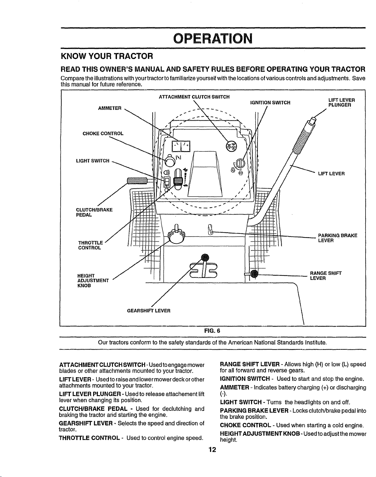
KNOW YOUR TRACTOR
READ THIS OWNER'S MANUAL AND SAFETY RULES BEFORE OPERATING YOUR TRACTOR
Compare the illustrationswith yourtractor to familiarize yourselfwiththelocations of variouscontrols and adjustments,. Save
this manual for future reference.
AMMETER
CHOKECONTROL
LIGHT SWITCH
ATTACHMENT CLUTCH SWITCH
LIFT LEVER
IGNITION SWITCH PLUNGER
/
I
t
/
• /
LIFT LEVER
CLUTCH/BRAKE
PEDAL
THROTTLE
CONTROL
PARKING BRAKE
LEVER
HEIGHT
ADJUSTMENT
KNOB
GEARSHIFT LEVER
FIG. 6
Our tractors conform to the safety standards of the American National Standards Institute°
RANGE SHIFT
LEVER
ATTACHMENT CLUTCH SWITCH - Used to engage mower
blades or other attachments mounted to your tractor,
LIFT LEVER- Used to raise and lower mower deck or other
attachments mounted to your tractor.
LIFT LEVER PLUNGER - Used to release attachement lift
lever when changing its position,
CLUTCH/BRAKE PEDAL - Used for declutching and
braking the tractor and starting the engine,
GEARSHIFT LEVER - Selects the speed and direction of
tractor,
THROTTLE CONTROL - Used to control engine speed,
12
RANGE SHIFT LEVER - Allows high (H) or low (L) speed
for all forward and reverse gears,
IGNITION SWITCH - Used to start and stop the engine,
AMMETER oIndicates battery charging (+) or discharging
(-).
LIGHT SWITCH - Turns the headlights on and off.
PARKING BRAKE LEVER _Locks clutch/brake pedal into
the brake position,
CHOKE CONTROL - Used when startinga cold engine,
HEIGHT ADJUSTMENT KNOB- Usedto adjust the mower
height.
.......... i,iii ir_,
OPERATION
The operation of any tractor can result in foreign objects thrown into the eyes, which can
result in severe eye damage, Always wear safety glasses or eye shields while operating
your tractor or performing any adjustments or repairs. We recommend a wide vision safety
mask over the spectacles or standard safety glasses.
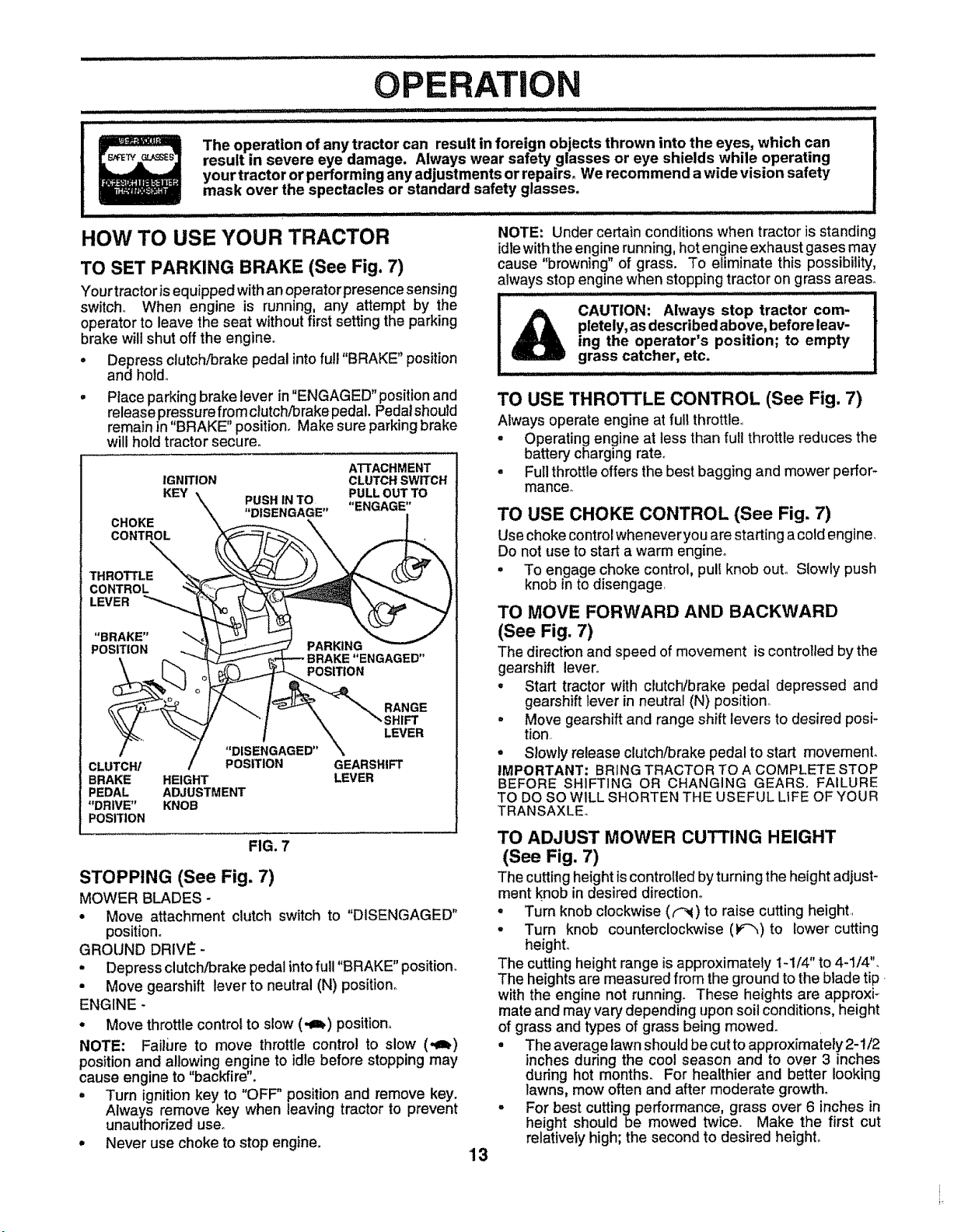
HOW TO USE YOUR TRACTOR
TO SET PARKING BRAKE (See Fig. 7)
Your tractoris equipped with an operator presence sensing
switch.. When engine is running, any attempt by the
operator to leave the seat without first setting the parking
brake will shut off the engine.
o Depress clutch!brake pedal into full "BRAKE" position
and holdo
• Place parking brake lever in "ENGAGED" position and
release pressure fromclutch/brake pedal. Pedal should
remain in "BRAKE" position. Make sure parking brake
will hold tractor secure.
ATTACHMENT
IGNITION CLUTCH SWITCH
KEY \ ........ PULL OUT TO
-,_ P'U_II1 tN/U "I=MP.&P.I="
x, "DISENGAGE ......... ,
CHOKE "\ f.----_ \ |
CONTROL ,K_---=_ _.._---_ \ _..1,
CONTROL _. ___\ _ I
"BRAKE" "- L_ _ .........
POS, ,o. ' "' ENGAGED"
_. [ _ _(_)_,._ POSITION
;i RANGE
_'%. -'_ .... ( ....... \\ LEVER
/ .... "DISENGAGED" \
CLUTCH/ / POSITION GEARSHIFT
BRAKE HEIGHT LEVER
PEDAL ADJUSTMENT
"DRIVE"KNOB
POSITION
FIG. 7
STOPPING (See Fig. 7)
MOWER BLADES -
• Move attachment clutch switch to "DISENGAGED"
position°
GROUND DRIVE -
• Depress clutch/brake pedal into full "BRAKE" position.
• Move gearshift lever to neutral (N) position°
ENGINE -
° Move throttlecontrol to slow (,a_) position.
NOTE: Failure to move throttle contm! to slow (,,_)
positionand allowing engine to idle before stopping may
cause engine to "backfire".
• Turn ignition key to "OFF" position and remove key.
Always remove key when leaving tractor to prevent
unauthorized use°
• Never use choke to stop engine.
NOTE: Under certain conditions when tractor is standing
idle with the engine running, hot engine exhaust gases may
cause "browning" of grass. To eliminate this possibility,
always stop engine when stopping tractor on grass areas.
CAUTION: Always stop tractor com-
pletely, as described above, before leav-
ing the operator's position; to empty
grass catcher, etc.
TO USE THROTTLE CONTROL (See Fig. 7)
Always operate engine at full throttle..
• Operating engine at less than full throttle reduces the
battery charging rate°
• Fullthrottleoffersthe best bagging and mower perfor-
mance_
TO USE CHOKE CONTROL (See Fig. 7)
Use choke controlwhenever youare starting a coldengine.
Do not use to start a warm engine°
= To engage choke control, pull knob ouL Slowly push
knob in to disengage,
TO MOVE FORWARD AND BACKWARD
(See Fig. 7)
The direction and speed of movement is controlled by the
gearshift lever°
° Start tractor with clutch/brake pedal depressed and
gearshift lever in neutral (N) position_
- Move gearshift and range shift levers to desired posi-
tion..
° Slowly release clutch/brake pedal to start movemenL
IMPORTANT: BRING TRACTOR TO A COMPLETE STOP
BEFORE SHIFTING OR CHANGING GEARS. FAILURE
TO DO SO WILL SHORTEN THE USEFUL LIFE OF YOUR
TRANSAXLE_
TO ADJUST MOWER CUTTING HEIGHT
(See Fig. 7)
The cuttingheightis controlledby turningthe height adjust-
ment knob in desired direction°
° Turn knob clockwise ((_) to raise cutting height..
- Turn knob counterclockwise (F"_)to lower cutting
heighL
The cutting height range is approximately t-1/4" to 4-1/4".
The heights are measured from the ground to the blade tip
with the engine not running. These heights are approx{-
mate and may vary depending upon soil conditions, height
of grass and types of grass being mowed.
• The average lawn should be cut to approximately 2-1/2
inches during the cool season and to over 3 inches
during hot months. For healthier and better looking
lawns, mow often and after moderate growth.
° For best cutting performance, grass over 6 inches in
height should be mowed twice. Make the first cut
relatively high; the second to desired heighL
'13
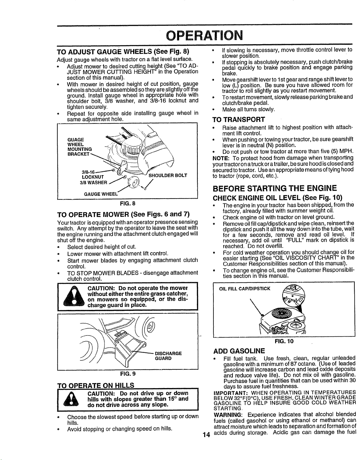
TO ADJUST GAUGE WHEELS(See Fig. 8)
Adjust gauge wheels with tractor on a flat level surface°
o Adjust mower to desired cutting height (See 'q'O AD_
JUST MOWER CUTTING HEIGHT' in the Operation
section of this manual)_
. With mower in desired height of cut position, gauge
wheels should be assembled so they are slightly off the
ground. Install gauge wheel in appropriate hole with
shoulder bolt, 3/8 washer, and 3/8-16 locknut and
tighten securely.
• Repeat for opposite side installing gauge wheel in
same adjustment hole.
GUAGE
WHEEL
MOUNTING
LOCKNUT
3_ WASHER
SHOULDER BOLT
GAUGE WHEEL
FIG. 8
TO OPERATE MOWER (See Figs. 6 and 7)
Your tractor isequipped with anoperator presence sensing
switch. Any attempt by the operator to leave the seat with
the engine running and the attachment clutch engaged will
shut off the engine.
o Select desired height of cut.
• Lower mower with attacIlment lift control
° Start mower blades by engaging attachment clutch
control.
° TO STOP MOWER BLADES - disengage attachment
clutch control,
CAUTION: Do not operate the mower
without either the entire grass catcher,
on mowers so equipped, or the dis-
charge guard in place.
......................... i Hi,lllllll i L L =l =l i=l=l=l=l=
DISCHARGE
GUARD
FIG. 9
TO OPERATE ON HILLS
I
............... E
CAUTION: Do not drive up or down
hills with slopes greater than 15° and
do not drive across any slope.
liH i ii i
Choose the slowest speed before starting up or down
hills.
Avoid stopping or changingspeed on hills.
i i illl iilllll i i iilllLL_I1:1_I_J
o if slowing is necessary, move throttle control lever to
slower position°
° If stopping is absolutely necessary, push clutch/brake
pedal quickly to brake position and engage parking
brake_
° Move gearshift lever to 1st gear and range shift lever to
low (L) position. Be sure you have allowed room for
tractor to roll slightly as you restart movemenL
= To restart movement, slowly release parkingbrake and
clutch/brake pedal.
• Make all turns slowly.
TO TRANSPORT
• Raise attachment lift to highest position with attach-
ment lift control
° When pushingortowing yourtractor, be sure gearshift
lever is in neutral (N) position.
• Do not push or tow tractor at more than five (5) MPH.
NOTE: To protect hood from damage when transporting
your tractor on a truck or atrailer, be sure hood is closed and
secured totractor. Use an appropriate means of tying hood
to tractor (rope, cord, etc.).
BEFORE STARTING THE ENGINE
CHECK ENGINE OIL LEVEL (See Fig. 10)
- The engine inyour'tractor has been shipped, from the
factory, already filled with summer weight oil..
, Check engine oil with tractor on level ground.
° Remove oil filecap/dipstick and wipe clean, reinsert the
dipstick and push it alt the way down intothe tube, wait
for a few seconds, remove and read oil level° If
necessary, add oil until "FULL" mark on dipstick is
reached. Do not overfill.
• For cold weather operation you should change oil for
easier starting (See "OIL VISCOSITY CHART" in the
Customer Responsibilities section of this manual).
• To change engine oil, see the Customer Responsibili-
ties section in this manual.
OIL FILL CAP/DIPSTICK
14
FIG. 10
ADD GASOLINE
• Fill fuel tank. Use fresh, clean, regular unleaded
gasolinewith a minimum of 87 octane, (Use of leaded
gasoline will increase carbon and lead oxide deposits
and reduce valve life). Do not mix oil with gasoline,
Purchase fuel in quantities that can be used within 30
days to assure fuel freshness.
IMPORTANT: WHEN OPERATING IN TEMPERATURES
BELOW 32°F(0°C), USE FRESH, (_LEANWINTER GRADE
GASOLINE TO HELP INSURE GOOD COLD WEATHER
STARTING
WARNING: Experience indicates that alcohol blended
fuels (called gasohol or using ethanol or methanol) can
attract moisture which leads to separation and formation of
acids during storage. Acidic gas can damage the fuel
OPERATION
................. i i i illllll
'system of an engine while in storage° To avoid engine
problems, the fuel system should be emptied before stor-
age of 30 days or longer. Drain the gas tank, start the
engine and let it run until the fuel tines and carburetor are
empty. Use fresh fuel next season. See Storage Instruc-
tions for additional information. Never use engine or
carburetor cleaner products in the fuel tank or permanent
damage may occur°
t&
CAUI"ION: Fill to bottom of gas tank
filler neck. Do not overfill. Wipe off any !
spilled oil or fuel. Do not store, spill or |
use. gasoline,,,n,ea,ran open flame. ................!
TO START ENGINE (See Fig. 7)
When starting engine for the first time or if engine has run
outof fuel, itwill take extra crankingtime to move fuel from
the tank to the engine.
• Depress clutch/brake pedal and set parking brake°
° Place gearshift lever in neutral (N) position°
, Move attachment clutch to "DISENGAGED" position_
° Pull choke control out to choke (N) position for cold
engine start. For warm engine start do not use choke
control
• Move throttle control to midway between fast (,_) and
slow (,41) positions.
° Insert key into ignition and turn keyclockwise to"START"
position and release key as soon as engine starts, Do
not run starter continuously for more than fifteen
seconds per minute_ if engine does not start after
several attempts, move throttle control to fast (,t_)
position, wait a few minutes and try again.
• When engine starts, slowly push choke control in.
• Move throttle control to fast (_) position.
° Allow engine to warm up for a few minutes before
engaging drive or attachments.
NOTE: If at a high attitude (above 3000 feet) or in cold
temperatures (below 32°F), the carburetor fuel mixture
may need to be adjusted for best engine performance. See
"TO ADJUST CARBURETOR" in the Service and Adjust-
ments section of this manual
MOWING TIPS
° Tire chains cannot be used when the mower housing
is attached to tractor.
° Mower should be properly leveled for best mowing
performance, See "TO LEVEL MOWER HOUSING" in
the Service and Adjustments section of this manual°
o The left hand side of mower should be used for trim-
ming.
° Drive so that clippings are discharged onto the area
that has been cut, Have the cut area to the right of the
machine This will result in a more even distribution of
clippings and more uniform cutting.
° When mowing large areas, start by turning to the right
so that clippings will discharge away from shrubs,
fences, driveways, etc. After one or two rounds, mow
in the opposite direction making left hand turns until
finished(See Fig. 10).
° If grass is extremely tall, it should be mowed twice to
reduce load and possible fire hazard from dried clip-
pings° Make first cut relatively high; the second to the
desired height.
° Do not mow grass when it is wet. Wet grass will plug
mower and leave undesirable clumps. Allow grass to
dry before mowing
• Always operate engine at full throttle when mowing to
assure better mowing performance and proper dis-
charge of matedalo Regulate ground speed by select-
ing a low enough gear to give the mower cutting
performance as well as the quality of cut desired.
• When operating attachments, select a ground speed
that will suit the terrain and give best performance of
the attachment being used.
f
1
t
J
FIG. 11
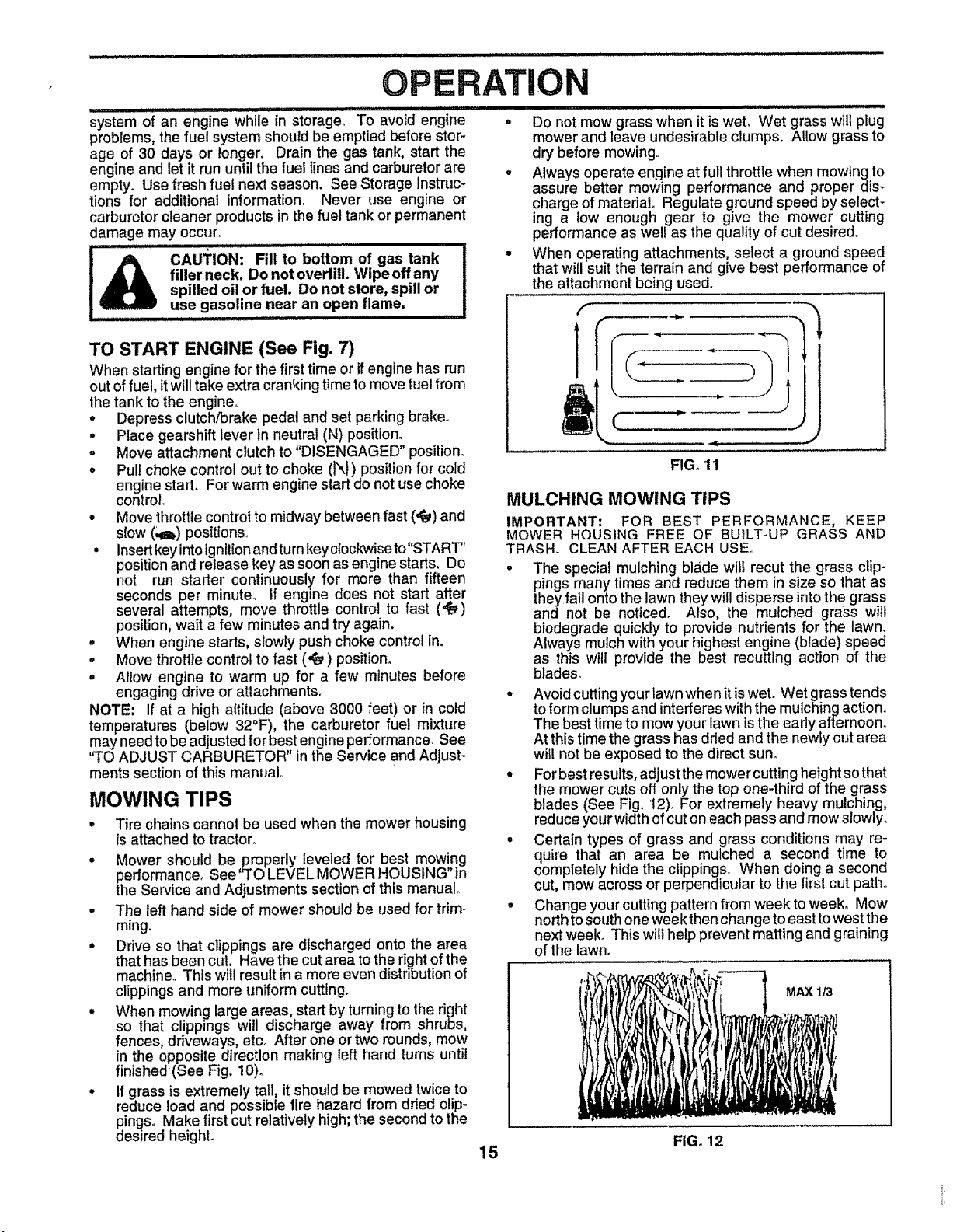
MULCHING MOWING TIPS
IMPORTANT: FOR BEST PERFORMANCE, KEEP
MOWER HOUSING FREE OF BUILT-UP GRASS AND
TRASH. CLEAN AFTER EACH USE
• The special mulching blade witf recut the grass clip-
pings many times and reduce them in size so that as
they fall onto the lawn they will disperse into the grass
and not be noticed. Also, the mulched grass will
biodegrade quickly to provide nutrients for the lawn.
Always mulch with your highest engine (blade) speed
as this will provide the best recutting action of the
blades_
° Avoid cutting your lawn when it is wet. Wet grass tends
to form clumps and interferes with the mulching action
The best time to mow your lawn is the early afternoon.
At this time the grass has dried and the newly cut area
will not be exposed to the direct sun
• For best results, adjust the mower cutting height so that
the mower cuts off only the top one-third of the grass
blades (See Fig. 12). For extremely heavy mulching,
reduce your width of cut on each pass and mow slowly.
° Certain types of grass and grass conditions may re-
quire that an area be mulched a second time to
completely hide the clippings_ When doing a second
cut, mow across or perpendicular to the first cut path.
• Change your cutting pattern from week to week. Mow
north to south one weekthen change to east to west the
next week. This will help prevent matting and graining
of the lawn.
MAX 1/3
FIG. 12
15
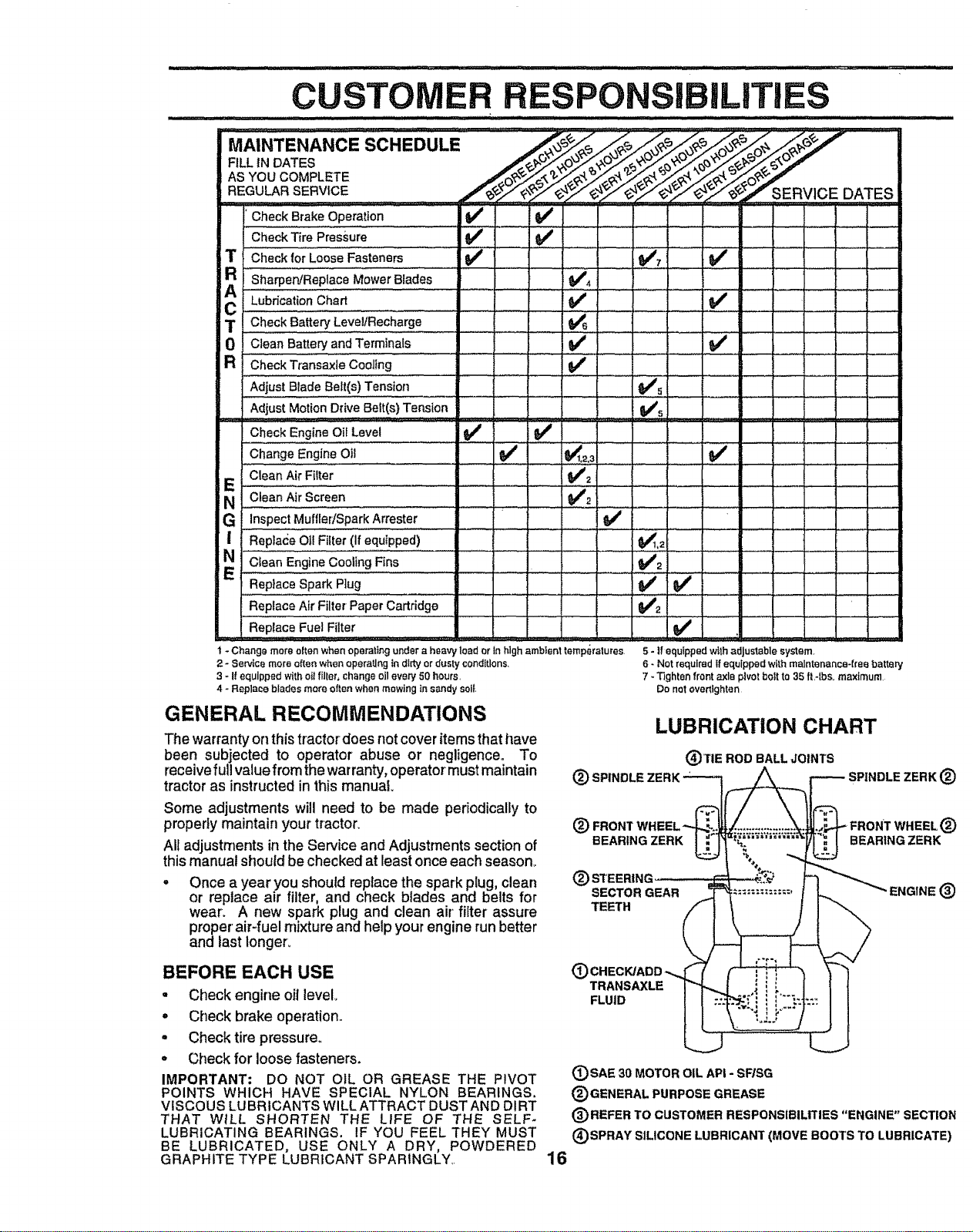
MAINTEN'ANCE SCHEDULE /__/_o_i_f '_ .......
AsYouCOMPLETE /__.7_,_ _.._.O_.>,"_
REGU_R SERVIC E ./'__,/'a_SERVICE DATES
Check Brake Operation
,,€,heokT_ePreesure ........ V" ..... _ ........... ..... ,
T CheckforLooseFasteners tf _:,
a Sharpen!ReplaceMowerBlades _#',
..............i ..................l.......v' ......' '
C ?.......................... ., I ...................... ...... ..........
ii Check .......Battery Level/Recharge .I , I._ _ ........
0 CleanBatteryandTerminals Q##
R 'C'heckT;ansaxlecOoling .............. _#'......
Adjust Blade Belt(s) Tension
Adjust Motion Ddve Belt(s) Tension
CheckEngineOil Level I_/
Change Engine Oil
CleanAir Filter I
NE Ciean Ai;
Screen
E.
G InspectMuffledSparkArrester
....... =
| ReplaceOilFilter(Ifequipped) $1_1.2
E" : ,i,,,i ............v'2 .
ReplaceSparkPlug _
ReplaceAir Filter PaperCartridge _#P2
=
Replace Fuel Filter
I - Change more often when operating under a heavy load or In high ambient temperatures,
2 - Service more often when operating in dirty or dusty conditions
3 - If equipped with oil filler, change oil every 50 hours,
4 - Replace blades more often when mowing in sandy soil,
_5
v"
5 - If equipped wtlh adjustable system,
6 - Not required If equipped with maintenance-free battery
7 _Tighten front axle plvot bolt to 35 fl,-lbs_ maximum,
Do not overtlghtan
GENERAL RECOMMENDATIONS
The warranty or] thistractor does not cover items that have
been subjected to operator abuse or negligence. To
receive full value from the warranty, operator must maintain
tractor as instructed in this manual
Some adjustments will need to be made periodically to
properly maintain your tractor.
All adjustments in the Service and Adjustments section of
this manual should be checked at least once each season_
Once a year you should replace the spark plug, clean
or replace air filter, and check blades and belts for
wear. A new spark plug and clean air' filter assure
proper air-fuel mixture and help your engine run better
and last longer..
LUBRICATION CHART
(_)TIE ROD BALL JOINTS
(_ SPINDLE ZERK __ _-_ SPINDLE ZERK (_
(_) FRONT WHEEL-"__...:. :._.:_,4._ FRONT WHEEL (_)
®
SECTOR GEAR "ENGINE (_)
TEETH
BEFORE EACH USE
- Check engine oil level
• Check brake operation..
• Checktire pressure.
° Check for loose fasteners.
IMPORTANT; DO NOT OIL OR GREASE THE PIVOT
POINTS WHICH HAVE SPECIAL NYLON BEARINGS.
VISCOUS LUBRICANTS WlLLATTRACT DUSTAND DIRT
THAT W_LL SHORTEN THE LIFE OF THE SELF-
LUBRICATING BEARINGS. IF YOU FEEL THEY MUST
BE LUBRICATED, USE ONLY A DRY, POWDERED
GRAPHITE TYPE LUBRICANT SPARINGLY..
TRANSAXLE
FLUID
16
(_SAE 30 MOTOR OIL API - SF/SG
® GENERAL PURPOSE GREASE
(_)REFER TO CUSTOMER RESPONSIBILITIES "ENGINE" SECTION
(_)SPRAY SILICONE LUBRICANT (MOVE BOOTS TO LUBRICATE)
CUSTOM
RESPONSIBILiTI
TRACTOR
Always observe safety rules when performing any mainte-
nanceo
BRAKE OPERATION
If unit requires more than six (6) feet stopping distance at
high speed in highest gear, then brake must be adjusted.
(See 'TO ADJUST BRAKE" in the Service and Adjust-
ments section of this manual)_
TIRES
• Maintain proper air pressure in all tires (See "PROD_
UCT SPECIFICATIONS" on page 3 of this manual)_
° Keep tires free of gasoline, oil, or insect control chemi-
cals which can harm n_bbero
. Avoid stumps, stones, deep ruts, sharp objects and
other hazards that may cause tire damage.
BLADE CARE
For best results mower blades must be kept sharp° Re-
place bent or damaged blades.
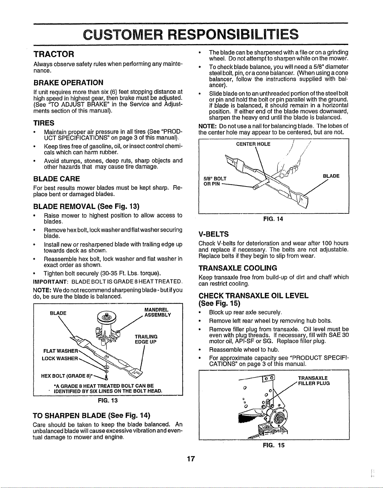
BLADE REMOVAL (See Fig. 13)
• Raise mower to highest position to allow access to
blades.
• Remove hex bolt, Iockwasher and flat washersecuring
blade.
° install new or resharpened blade with trailing edge up
towards deck as shown_
° Reassemble hex bolt, lock washer and flat washer in
exact order as shown,.
° Tighten bolt securely (30-35 Fto Lbsotorque).
IMPORTANT: BLADE BOLT IS GRADE 8 HEATTREATED.
NOTE: We do not recommend sharpening blade- but if you
do, be sure the blade is balanced°
MANDREL
B LA._\_. _ ASSEMBLY
HEX BOLT (GRADE 8)*-,_,,_ "_
"A GRADE 8 HEAT TREATED BOLT CAN BE
' IDENTIFIED BY SIX LINES ON THE BOLT HEAD,
FIG. 13
TO SHARPEN BLADE (See Fig. 14)
Care should be taken to keep the blade balanced. An
unbalanced blade will cause excessive vibration and evem
tual damage to mower and engine°
• The blade can be sharpened with a file or on a grinding
wheel° Do not attempt to sharpen white on the mower.
• To check blade balance, you will need a 5/8" diameter
steel bolt, pin, era cone balancer. (When using a cone
balancer, follow the instructions supplied with bal-
ancer).
• Slide blade on to an unthreaded portion of the steel bolt
or pin and hold the bolt or pin parallel with the ground.
tf blade is balanced, it Should remain in a horizontal
position_ If either end of the blade moves downward,
sharpen the heavy end until the blade is balanced.
NOTE: Do not use a nail for balancing blade. The lobes of
the center hole may appear to be centered, but are not.
/
CENTER HOLE /
_ ,(/ //
518"BOLT BLADE
FIGo 14
V-BELTS
Check V-belts for deterioration and wear after 100 hours
and replace if necessary. The belts are not adjustable_
Replace beffs if they begin to slip from wear.
TRANSAXLE COOLING
Keep transaxle free from build-up of dirt and chaff which
can restrict cooling.
CHECK TRANSAXLE OIL LEVEL
(See Fig. 15)
° Block up rear axle securely.
o Remove left rear wheel by removing hub bolts,.
° Remove filler plug from transaxleo Oil level must be
even with plug threads. If necessary, fill with SAE 30
motor oil, API-SF or SG. Replace filler plug.
= Reassemble wheel to hub,.
° For approximate capacity see "PRODUCT SPECIFI-
CATIONS" on page 3 of this manual
O
o
TRANSAXLE
FIG. 15
17
ii ii illlll ........................................
CU
BATTERY
Your tractor has a battery charging system which is suffi-
cient for normal use. However, periodic charging of the
battery with an automotive charger will extend its life.
• Keep battery and terminals cleano
• Keep battery bolts tight.
o Keep small vent holes open.
= Recharge at 6-10amperes for 1 hour.
TO CLEAN BATTERY AND TERMINALS
Corrosion and dirt on the battery and terminals can cause
the battery to "leak" power_
° Remove terminal guard
° Disconnect BLACK battery cable first then RED bat-
tery cable and remove battery from tractor.
,, Rinse the battery with plain water and dry.
= Clean terminals and battery cable ends with wire brush
until bright,
• Coat terminals with grease or petroleum jelly.
. Reinstall battery (See "CONNECT BATTERY" in the
Assembly section of this manual).
i
liH, iHlllll ii H
Change the oil after the first two hours of operation and
every' 50 hours thereafter or at least once a year if the
tractor is not used for 50 hours in one year.
ENGINE
LUBRICATION
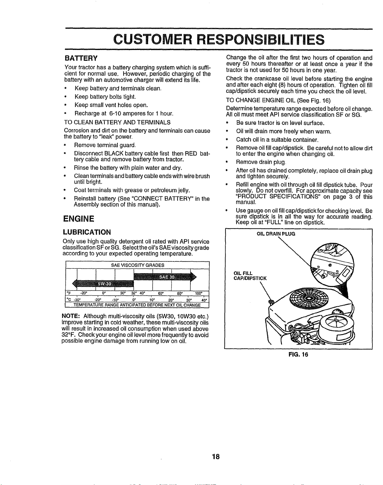
Only use high quality detergent oil rated with API service
classification SF or SG. Select the oil's SAE viscosity grade
according to your expected operating temperature.
SAE VISCOSITY GRADES
'_F -20 _ 0 _ 30 = 32" 40" 60" 80 = t_'*
_C -30" -20= -10° O" 10" 20" 30° 40*
TEMPERATURE RANGE ANTICIPATED BEFORE NEXT O{L CHANGE
NOTE: Although multi-viscosity oils (5W30, 10W30 etco)
improve starting in cold weather, these multi-viscosity oils
will result in increased oil consumption when used above
32°F. Check your engine oil level more frequently to avoid
possible engine damage from running low on oil
Check the crankcase oil level before starting the engine
and after each eight (8) hours of operation, Tighten oil fill
cap/dipstick securely each time you check the oil level
TO CHANGE ENGINE OIL (See Fig_ 16)
Determine temperature range expected before oit change.
At1oil must meet AP1service classification SF or SG_
° Be sure tractor is on level surface.
o Oil will drain more freely when warm.
° Catch oil ina suitable container.
o Remove oil fill cap/dipstick, Be careful not to allow dirt
to enter the engine when changing oil,
• Remove drain plug
• After oil has drained completely, replace oil drain plug
and tighten secure[yo
° Refill engine with oil through oil fill dipstick tube. Pour
slowly. Do not overfill. For approximate capacity see
"PRODUCT SPECIFICATIONS" on page 3 of this
manual.
Use gauge on oil fill cap/dipstick for checking level. Be
sure dipstick is in all the way for accurate reading°
Keep oil at "FULL" line on dipstick.
OIL DRAIN PLUG
OIL FILL
CAP/DIPSTICK
FIG. 16
18
C R
SIBILITIES
FIG. 18
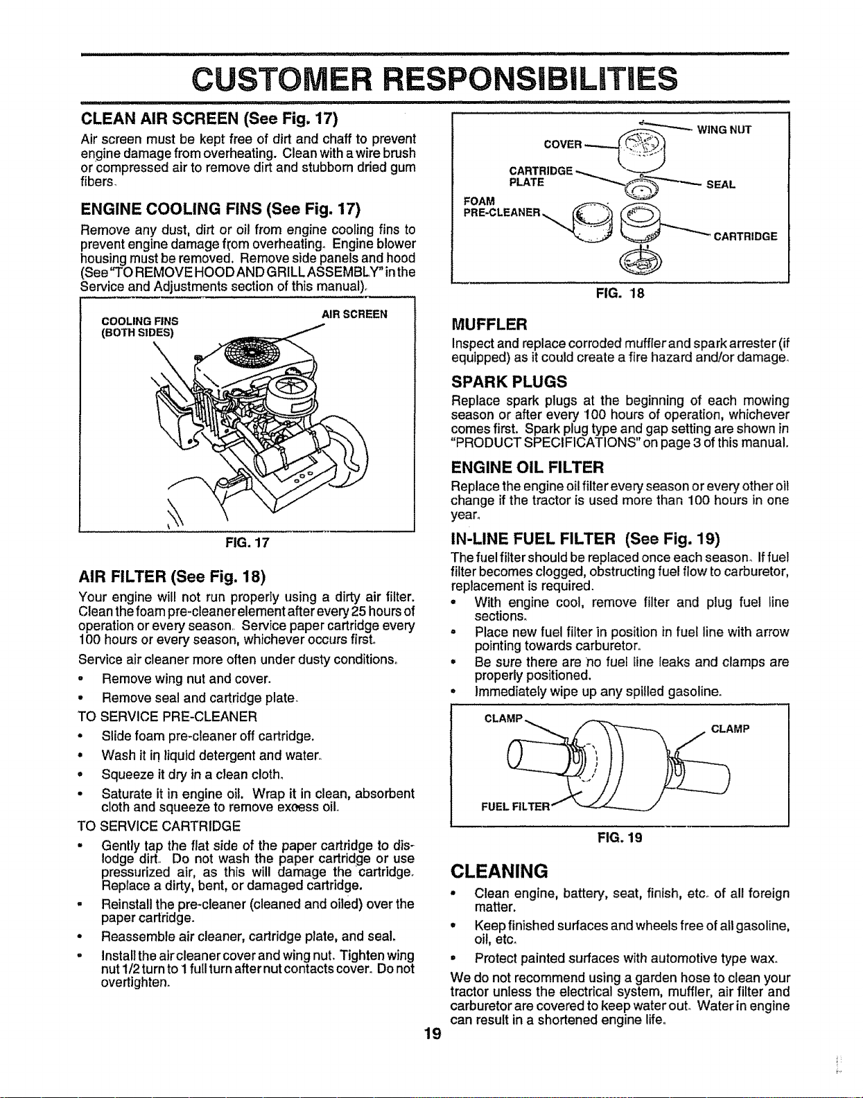
CLEAN AIR SCREEN (See Fig. 17)
Air screen must be kept free of dirt and chaff to prevent
engine damage from overheating. Clean with awire brush
or compressed air to remove dirt and stubborn dded gum
fibers_
ENGINE COOLING FINS (See Fig. 17)
Remove any dust, dirt or oil from engine cooling fins to
prevent engine damage f[om overheating° Engine blower
housingmust be removed. Remove side panels and hood
(See"TO REMOVE HOOD AND GRILLASSEMBLY inthe
Service and Adjustments section of this manual).
_""'_'"-_WING NUT
SEAL
CARTRIDGE
COOLING FINS
(BOTH SIDES)
AIR SCREEN
\
\
FIG. 17
AIR FILTER (See Fig. 18)
Your engine will not run properly using a dirty air filter.
Clean the foam pre-cleaner element after every 25 hours of
operation or every season Service paper cartridge every
100 hours or every season, whichever occurs first°
Service air cleaner more often under dusty conditions.
. Remove wing nut and cover.
• Remove seal and cartridge plate.
TO SERVICE PRE-CLEANER
• Slide foam pre-cleaner off cartridge.
• Wash it in liquiddetergent and water,
• Squeeze it dry in a clean c!oth_
• Saturate it in engine oil. Wrap it in clean, absorbent
cloth and squeeze to remove exoess oil,
TO SERVICE CARTRIDGE
• Gently tap the flat side of the paper cartridge to dis-
lodge dirt., Do not wash the paper cartridge or use
pressurized air, as this will damage the cartridge.
Replace a dirty, bent, or damaged cartridge.
. Reinstall the pre-cleaner (cleaned and oiled) over the
paper cartridge.
• Reassemble air cleaner, cartridge plate, and seal.
- Install the aircleaner cover and wing nut. Tighten wing
nut 1/2 turn to 1 full turn after nut contacts cover. Do not
overtighten.
MUFFLER
Inspect and replace corroded muffler and spark arrester (if
equipped) as it could create a fire hazard and/or damage°
SPARK PLUGS
Replace spark plugs at the beginning of each mowing
season or after every 100 hours of operation, whichever
comes first. Spark plug type and gap setting are shown in
"PRODUCT SPECIFICATIONS" on page 3 of this manual.
ENGINE OIL FILTER
Replace the engine oil filter every season or every other oil
change if the tractor is used more than 100 hours in one
year.
IN-LINE FUEL FILTER (See Fig. 19)
The fuel filter should be replaced once each season_ if fuel
filter becomes clogged, obstructingfuel flow to carburetor,
replacement is required.
• With engine cool, remove filter and plug fuel line
sections.
° Place new fuel filter in position in fuel line with arrow
pointing towards carburetor°
° Be sure there are no fuel line leaks and clamps are
properlypositioned.
• Immediately wipe up any spilled gasoline.
CLAMP _ 1----_
FUEL FILTER""
FIG. 19
19
CLEANING
• Clean engine, battery, seat, finish, etc_ of all foreign
matter.
• Keep finished surfaces and wheels free of all gasoline,
oil, etc.
° Protect painted surfaces with automotive type wax.
We do not recommend using a garden hose to clean your
tractor unless the electrical system, muffler, air filter and
carburetor are covered to keep water out. Water in engine
can result in a shortened engine life.
A ADJUSTMENTS
mmmm m_uuu mHmimmmmmm : m,, .... T .......................... ........... :"
CAUTION: BEFORE PERFORMING ANY SERVICE OR ADJUSTMENTS:
• Depress clutcF_t:mrakepedal fully and set parking brake,
° Place gearshift lever in neutral (N) position,
° Place attachment clutch in "DISENGAGED" position,
° Turn ignition key "OFF" and remove key,
° Make sure the blades and all moving parts have completely stopped.
o
Disconnect spark plug wire from spark plug and place wire where it cannot come in contact
with plug,
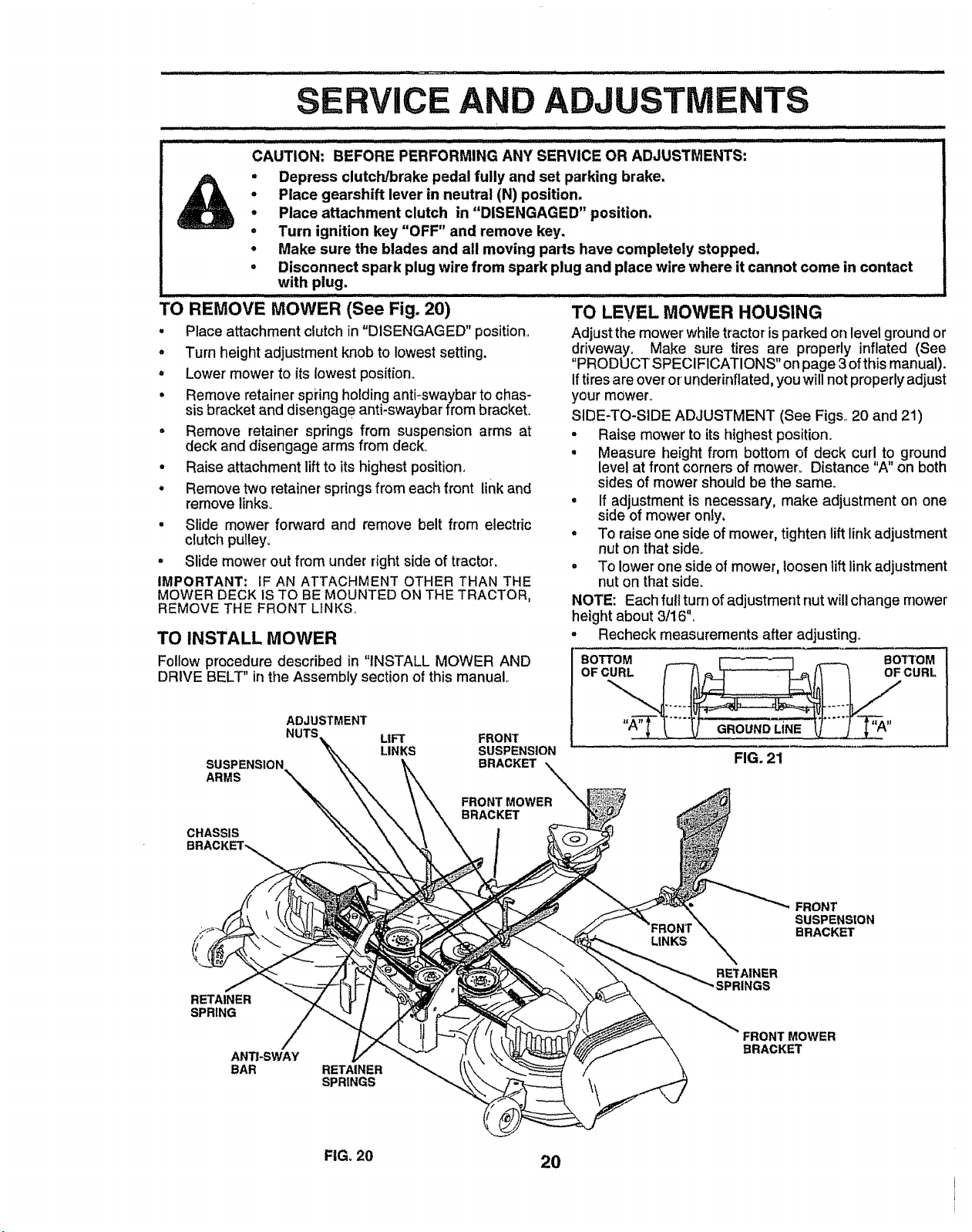
TO REMoVE'MOWER (See Fig. 20) ....
o Place attachment clutch in "DISENGAGED" position,,
. Turn height adjustment knob to lowest setting.
° Lower' mower to its lowest position°
• Remove retainer spiing holding anti-swaybar to chas-
sis bracket and disengag e anti-swaybar from brackeL
o Remove retainer springs from suspension arms at
deck and disengage arms from deck°
- Raise attachment lift to its highest position,
o Remove two retainer springs from each front link and
remove links..
° Slide mower forward and remove belt from electric
clutch pulley.
° Slide mower out from under right side of tractor,
IMPORTANT; IF AN ATTACHMENT OTHER THAN THE
MOWER DECK 1STO BE MOUNTED ON THE TRACTOR,
REMOVE THE FRONT LINKS.
TO INSTALL MOWER
TO LEVEL MOWER HOUSING
Adjust the mower while tractor isparked on level ground or
driveway, Make sure tires are properly inflated (See
"PRODUCT SPECIFICATIONS" onpage 3 ofthis manual).
if tires are overor'underinflated,you will notproperlyadjust
your mower_
SIDE-TO-SIDE ADJUSTMENT (See Figs..20 and 21)
o Raise mower to its highest position.
• Measure height from bottom of deck curl to ground
level at front corners of mower° Distance "A"on both
sides of mower should be the same,
• If adjustment is necessary, make adjustment on one
side of mower only,
° To raise one side of mower, tighten lift link adjustment
nut on that side,,
o To lower one side of mower, loosen lift link adjustment
nut on that side.
NOTE: Each full turn of adjustment nut will change mower
height about 3/16",
° Recheck measurements after adjusting°
Follow procedure described in "INSTALL MOWER AND
DRIVE BELT" in the Assembly section of this manual°
ADJUSTMENT
SUSPENSION
ARMS
CHASSIS
BRACKET%
UFT
LINKS
FRONT
SUSPENSION
BRACKET
FIG. 21
RETAINER
SPRING
ANTI-SWAY
BAR RETAINER
SPRINGS
LINKS
FRONT
SUSPENSION
BRACKET
RETAINER
FRONT MOWER
BRACKET
FIG, 20
20
(
(
................................. i,,t ii, i , ii ,i i i ,u ,i..... i, ,, i,r,_,ll i, nl,ii
SERVICE AND ADJUSTMENTS
= i = = i,= i,nl i lu=. I=I..II=U=UnH..=H.H==HUH.Ul.lt
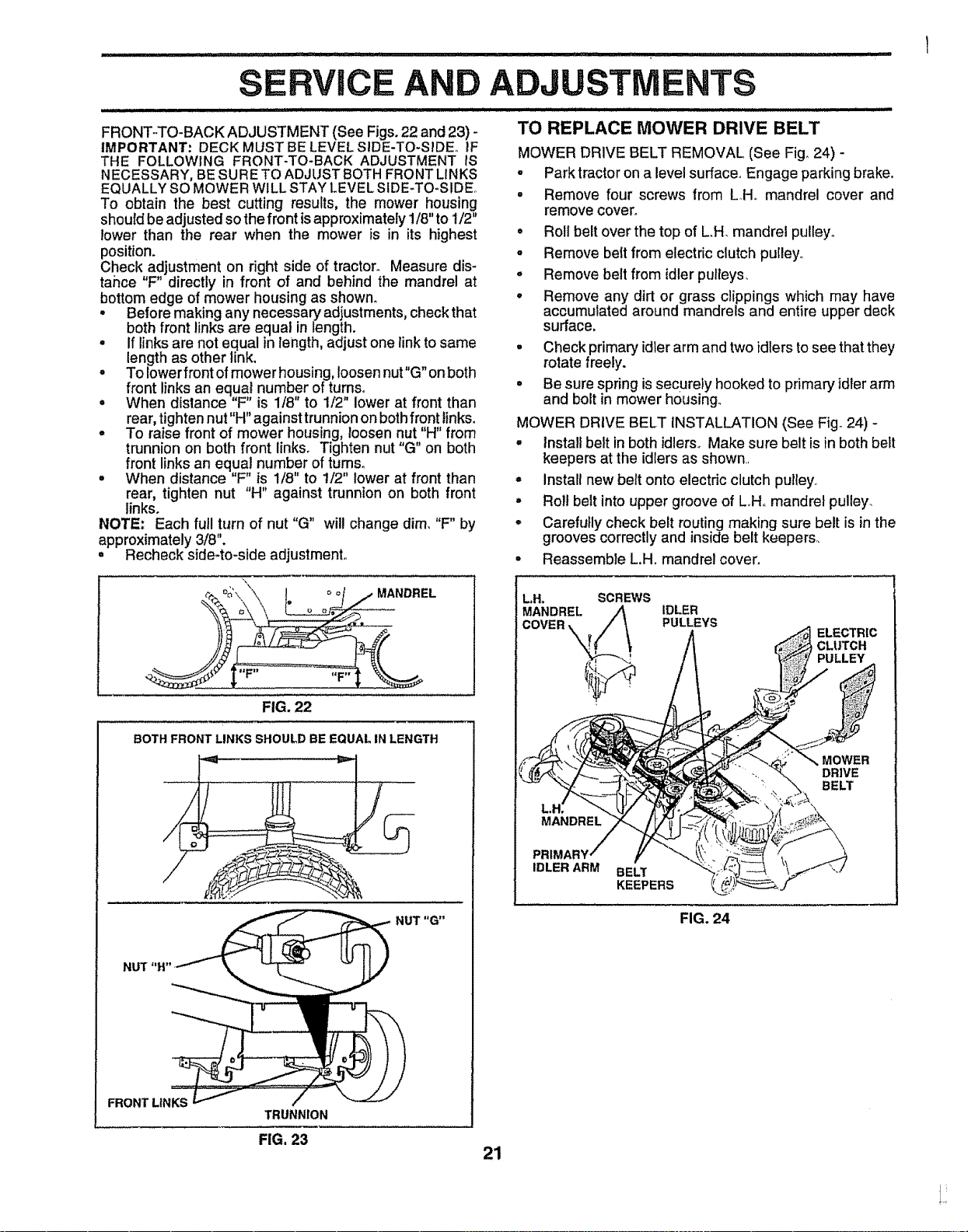
FRONT-TO-BACK ADJUSTMENT (See Figs° 22 and 23) -
IMPORTANT-" DECK MUST BELEVEL SlDE-TO-S_DE_ IF
THE FOLLOWING FRONT-TO-BACK ADJUSTMENT IS
NECESSARY, BE SURETO ADJUST BOTH FRONT LINKS
EQUALLY SO MOWER WILL STAY LEVEL SIDE-TO-SIDE,.
To obtain the best cutting results, the mower housing
should be adjusted so the front is approximately 1/8" to 1/2"
lower than the rear when the mower is in its highest
position.
Check adjustment on right side of tractor. Measure dis-
tance "F" directly in front of and behind the mandrel at
bottom edge of mower housing as shown.
Before making any necessary adjustments, check that
both front links are equal in length.
. if links are not equal in length, adjust one link to same
length as other link.
• To Iowerfront of mower housing, loosen nut"G" on both
front links an eq,ua! number of turns.
• When distance F is 1/8" to 1/2" lower at front than
rear, tighten nut "H" against trunnion on both fr,on!tinkso
° To raise front of mower housing, loosen nut H from
trunnion on both front links. Tighten nut "G" on both
front links an equal number of tumso
o When distance "F" is 1/8" to 1/2" lower at front than
rear, tighten nut "H" against trunnion on both front
links.
NOTE: Each full turn of nut "G" will change dim, "F" by
approximately 3/8".
° Recheck side-to-side adjustment,.
_'\\\. ! oo/ j MANDREL
FIG. 22
BOTH FRONT LINKS SHOULD BE EQUAL IN LENGTH
FRONT LINKS
NUT "G"
TO REPLACE MOWER DRIVE BELT
MOWER DRIVE BELT REMOVAL (See Fig° 24) -
• Park tractor on a level surface° Engage parking brake.
• Remove four screws from LH. mandrel cover and
remove cover°
° Rol! belt over the top of L.H. mandrel pulley°
- Remove belt from electric clutch pulley,,
° Remove belt from idler pulteys_
° Remove any dirt or grass clippings which may have
accumulated around mandrels and entire upper deck
surface.
° Check primary idler arm and two idlers to see that they
rotate freely.
• Be sure spring is securely hooked to primary idler arm
and bolt in mower housing.
MOWER DRIVE BELT INSTALLATION (See Fig. 24) -
° Install belt in both idlers,, Make sure belt is in both be_t
keepers at the idlers as shown,
° install new belt onto electdc clutch pulley.,
° Roll belt into upper groove of L,,H,,mandrel pulley.
° Carefully check belt routing making sure belt is in the
grooves correctly and inside belt keepers,
• Reassemble L.H. mandrel cover_
TRUNNION
FIG, 23
L.H, SCREWS
MANDREL
IDLER
PULLEYS
ELECTRIC
CLUTCH
PULLEY
MOWER
DRIVE
BELT
IDLER ARM
BELT
KEEPERS
FIG. 24
21
S
A
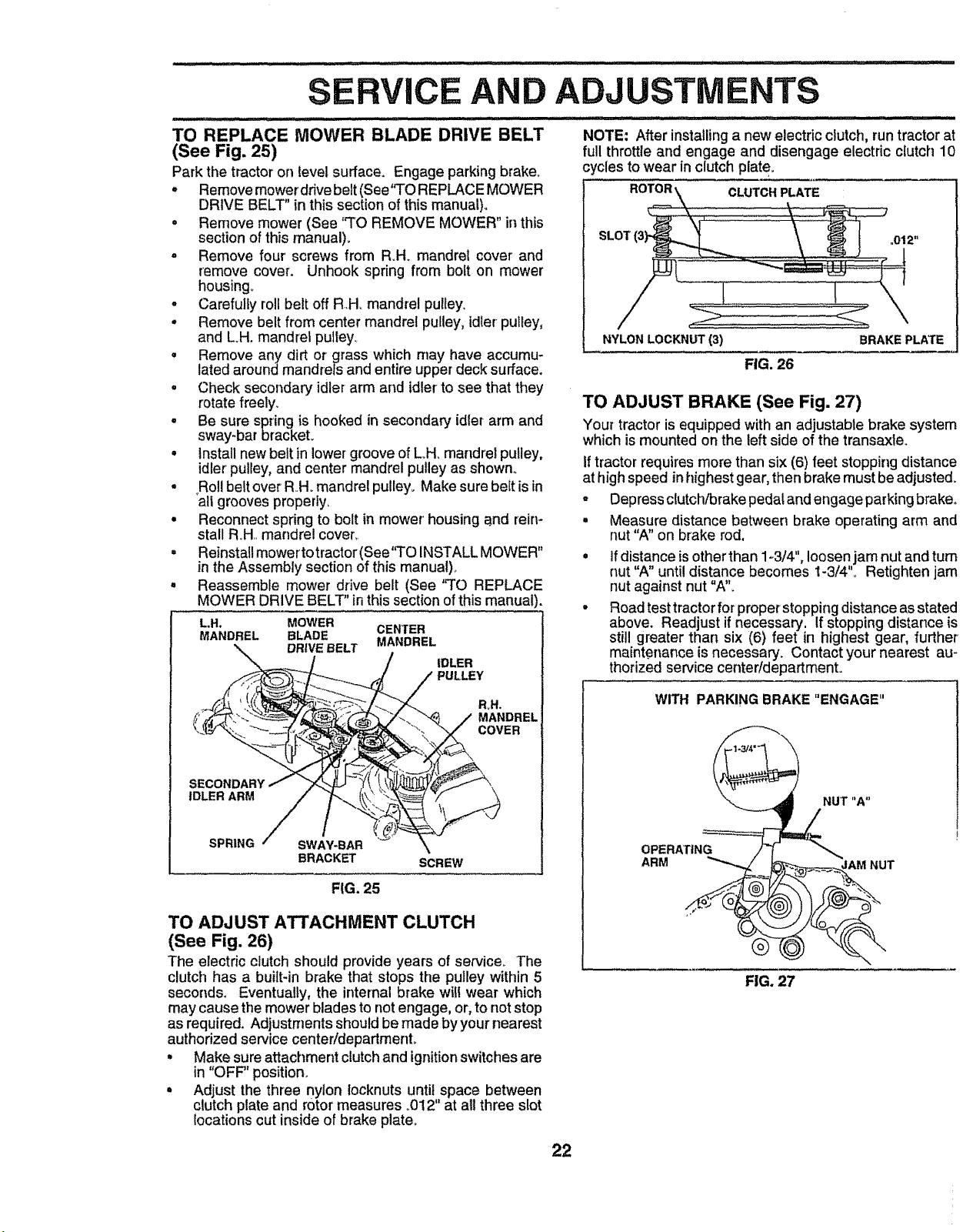
TO REPLACE MOWER BLADE DRIVE BELT
(See Fig. 25)
Park the tractor on level surface. Engage parking brake°
° Remove mowerdrive belt (See'`TO REPLACE MOWER
DRIVE BELT" in this section of this manual).
• Remove mower (See '`TO REMOVE MOWER" in this
section of this manual).
- Remove four' screws from R.H,, mandrel cover and
remove cover. Unhook spring from bolt on mower
housing,,
- Carefully roll belt off RHo mandrel pulley.
° Remove belt from center mandrel pulley, idler pu_ey,
and LH. mandrel pulley,
• Remove any dirt or grass which may have accumu-
lated around mandrels and entire upper deck surface.
° Check secondary idler arm and idler to see that they
rotate freely.
• Be sure spring is hooked in secondary idler arm and
sway-bar bracket.
• install new belt in lower groove of L,,H, mandrel pulley,
idler pulley, and center mandrel pulley as shown.
• Roll belt over RHo mandrel pulley. Make sure be{t is in
air grooves properly,
• Reconnect spring to bolt in mower housing _.nd rein-
stall Roll,, mandrel cover,.
• Reinstall mower to tractor (See'q'O INSTALL MOWER"
in the Assembly section of this manual)°
. Reassemble mower drive belt (See "TO REPLACE
MOWER DRIVE BELT" in this section of this manual).
L.H, MOWER CENTER
MANDREL BLADE
DRWE BELT MANDREL
IDLER
PULLEY
ADJUSTMENTS
NOTE: After installinga new electric ctutch, run tractor at
full throttleand engage and disengage electric clutch 10
cycles to wear in clutch plate_
NYLON LOCKNUT (3)
FIG. 26
BRAKE PLATE
TO ADJUST BRAKE (See Fig. 27)
Your tractor is equipped withan adjustabte brake system
which is mounted onthe left side of the transaxte.
If tractor requires more than six (6) feet stopping distance
at high speed in highest gear, then brake must be adjusted.
R_H.
MANDREL
COVER
IDLER ARM
SPRING SWAY-BAR \
BRACKET SCREW
FIG. 25
TO ADJUST ATTACHMENT CLUTCH
(See Fig. 26)
The electric clutch should provide years of service° The
clutch has a built-in brake that stops the pulley within 5
seconds. Eventually, the internal brake witl wear which
may cause the mower blades to not engage, or, to not stop
as required. Adjustments should be made by your nearest
authorized service centeridepartmento
° Make sure attachment clutchand ignitionswitchesare
in "OFF" position.
° Adjust the three nylon locknuts until space between
clutch plate and rotor measures _012"at all three slot
locations cut inside of brake plate,,
° Depress clutch/brake pedal and engage parking brake.
• Measure distance between brake operating arm and
nut "A" on brake rod.
if distance is other than 1-3/4", loosen jam nut and turn
nut "A until distance becomes 1-3/4"o Retighten jam
nut against nut "A".
Road test tractor for proper stopping distance as stated
above. Readjust if necessary, If stopping distance is
still greater than six (6) feet in highest gear, further
mainter_ance is necessary. Contact your nearest au-
thorized service center/department.
WITH PARKING BRAKE "ENGAGE"
OPERATING
ARM
FIG. 27
22
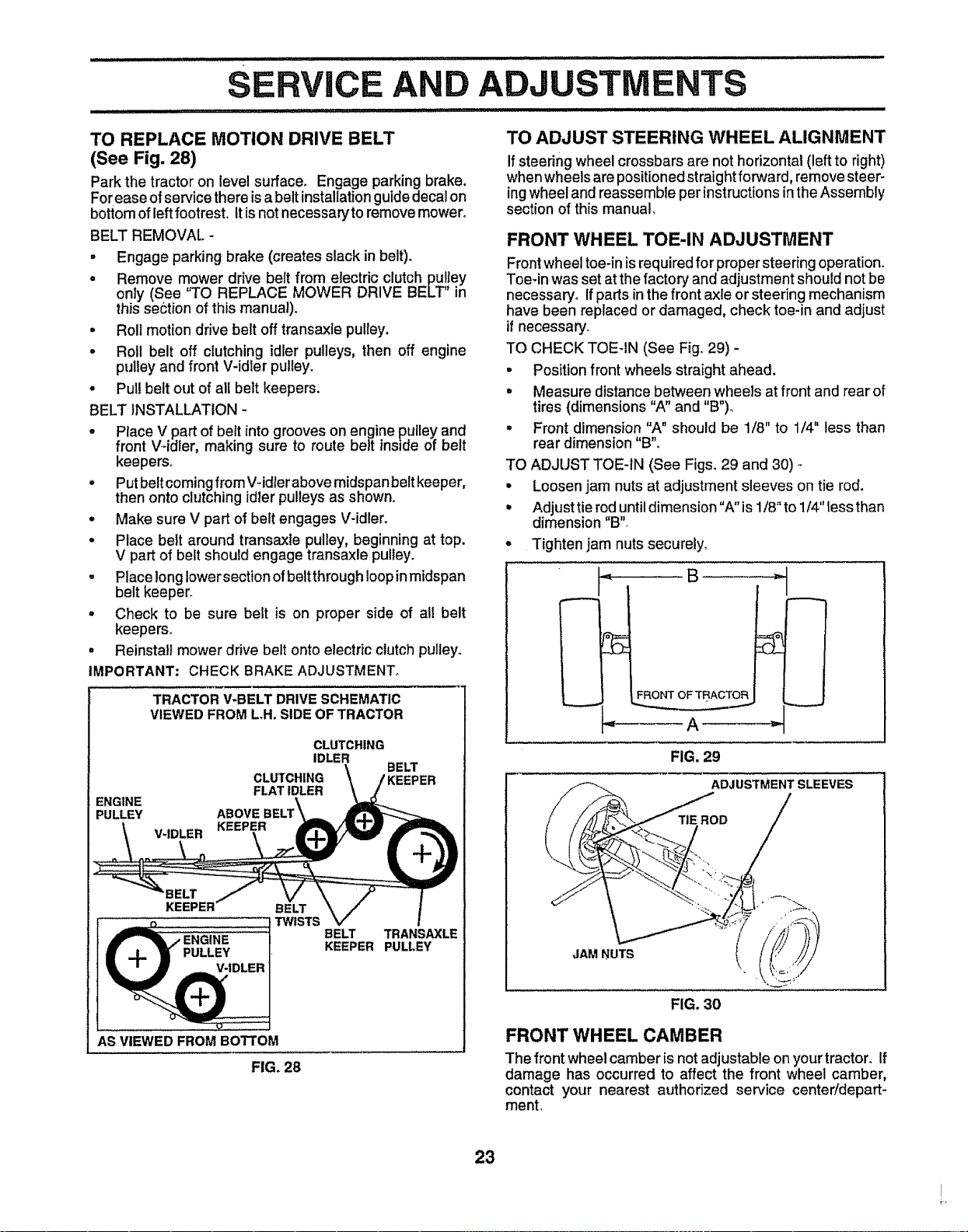
E AND
.... ii L,IJlI,I ,,i,1,1,1,I,
ADJUSTMENTS
TO REPLACE MOTION DRIVE BELT
(See Fig. 28)
Park the tractor on level sufface_ Engage parking brake.
Forease ofservice there isa beltinstallationguidedecal on
bottomof leftfootrest. Itis not necessary to remove mower°
BELT REMOVAL -
- Engage parking brake (creates slack in belt)_
o Remove mower drive belt from electric clutch pulJey
only (See "TO REPLACE MOWER DRIVE BELT" in
this section of this manual).
° Roll motion drive belt off transaxle pulley.
° Roll belt off clutching idler pulleys, then off engine
pulley and front V-idler pulley.
° Pull belt out of all belt keepers.
BELT iNSTALLATION -
• Place V partof belt into grooves on engine pulleyand
front V-idler, making sure to route belt inside of belt
keepers°
° Put beltcomingfrom V-idlerabove midspan beltkeeper,
then onto clutching idler pulleys as shown°
° Make sure V part of belt engages V*idler_
- Place belt around transaxte pulley, beginning at top.
V part of belt should engage transaxte pultey.
° Placelong Iowersectionofbeltthrough Ioopin midspan
belt keeper_
° Check to be sure belt is on proper side of ai! belt
keepers°
° Reinstall mower drive belt onto electric clutch pulley_
IMPORTANT: CHECK BRAKE ADJUSTMENT°
TRACTOR V-BELT DRIVE SCHEMATIC
VIEWED FROM L,H. SIDE OF TRACTOR
ENGINE
PULLEY
V-IDLER
CLUTCHING
IDLER
BELT
CLUTCHING
FLAT IDLER
ABOVE BELT\
KEEPER
BELT
TWISTS
BELT TRANSAXLE
KEEPER PULLEY
AS VIEWED FROMBOTTOM
FIG. 28
TO ADJUST STEERING WHEEL ALIGNMENT
If steering wheel crossbars are not horizontal (left to right)
when wheels are positioned straight forward, remove steer-
ing wheel and reassemble per instructions in the Assembly
section of this manual.
FRONT WHEEL TOE-IN ADJUSTMENT
Front wheel toe-in isrequired for proper steering operation.
Toe-in was set at the factory and adjustment should not be
necessary. If parts in the front axle or steering mechanism
have been replaced or damaged, check toe-in and adjust
if necessary.
TO CHECK TOE_IN (See Fig. 29) -
• Position front wheels straight ahead.
• Measure distance between wheels at front and rear of
tires (dimensions "A" and "B")_
• Front dimension "A" should be 1/8" to 1/4" less than
rear dimension "B"o
TO ADJUST TOE-IN (See Figs. 29 and 30)
• Loosen jam nuts at adjustment sleeves on tie rod.
• Adjust tie rod until dimension "A" is 1/8" to 1/4" less than
dimension "B".
" Tighten jam nuts securely°
B
FRONT OF TRACTOR
A
FIG. 29
ADJUSTMENT SLEEVES
TIE ROD
JAM NUTS
FIG. 30
FRONT WHEEL CAMBER
The front wheel camber is not adjustable on your tractor. If
damage has occurred to affect the front wheel camber,
contact your nearest authorized service center/depart-
menL
23
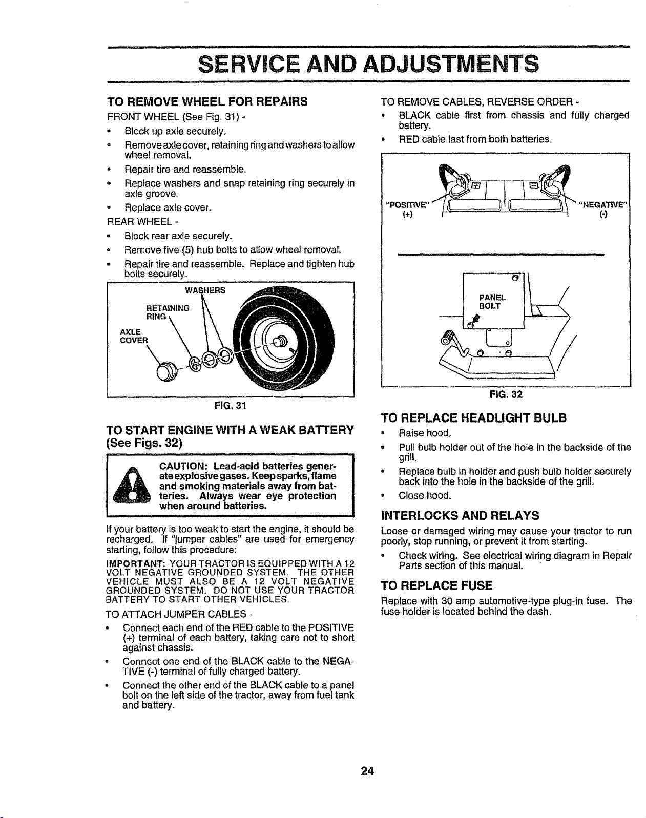
SERVICE AND ADJUSTMENTS
................... : ........................ .... t ,,,t .... _' ,t
TO REMOVE WHEEL FOR REPAIRS
FRONT WHEEL (See Fig° 31) -
• Block up axle securely.
• Remove axle cover, retainingringand washers toallow
wheel remova!,
. Repair tire and reassemble_
,, Replace washers and snap retainingring securely in
axle groove,
• Replace axle cover.
REAR WHEEL -
• Block rear' axle securely°
o Remove five (5) hub bolts to allow wheel removal,
. Repair tire and reassemble° Replace and tighten hub
botts securely.
WASHERS
RETAINING
RING _\\
AXLE \
COVER \
FIG. 31
TO START ENGINE WITH A WEAK BATTERY
See Figs. 32)
CAUTION: Lead-acid batteries gener-
ateexplosive gases. Keep sparks, flame
and smoking materials away from bat-
teries, Always wear eye protection
when around batteries.
If your battery is too weak to s!,,art the engine, it should be
recharged. If _jumper cables are used for emergency
starting, follow this procedure:
IMPORTANT: YOUR TRACTOR IS EQUIPPED WITH A 12
VOLT NEGATIVE GROUNDED SYSTEM. THE OTHER
VEHICLE MUST ALSO BE A 12 VOLT NEGATIVE
GROUNDED SYSTEM. DO NOT USE YOUR TRACTOR
BATTERY TO START OTHER VEHICLE&
TO ATTACH JUMPER CABLES -
- Connect each end of the RED cable to the POSITIVE
(+) terminal of each battery, taking care not to short
against chassis°
o Connect one end of the BLACK cable to the NEGA-
TIVE (-) terminal of fully charged battery.
° Connect the other end of the BLACK cable to a panel
bolt on the left side of the tractor, away from fuel tank
and battery.
TO REMOVE CABLES, REVERSE ORDER -
° BLACK cable first from chassis and fully charged
battery.
= RED cable last from both batteries°
"POSITIVE" _ ! _ "NEGA"_IVE"
(+) ' (4
O
PANEL
BOLT
FIG. 32
TO REPLACE HEADLIGHT BULB
• Raise hood_
• Pull bulb holder out of the hole in the backside of the
grill,
° Replace bulb in holder and push bulb holder securely
back into the hole in the backside of the gdlio
• Close hood.
INTERLOCKS AND RELAYS
Loose or damaged wiring may cause your tractor to run
poorly, stop running, or prevent it from starting.
• Check wiring. See electrical wiring diagram in Repair
Parts section of this manual°
TO REPLACE FUSE
Replace with 30 amp automotive4ype plug-in fuse. The
fuse holder is located behind the dash.
24
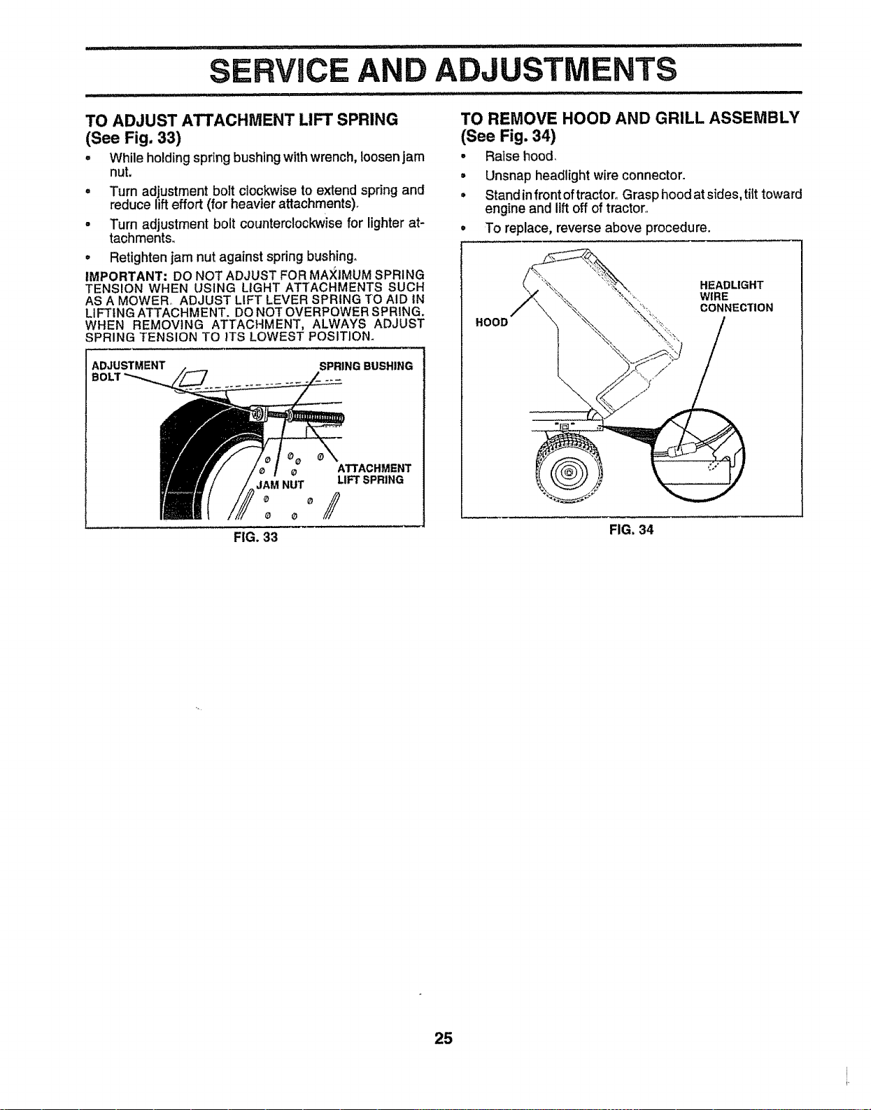
]1 i,i rlrl......................................... r 'll,i ii'_l_ ,,llll,,ll,ll,, ::
CE AND ADJUSTMENTS
TO ADJUST ATTACHMENT LIFT SPRING
(See Fig. 33)
. While holdingspring bushingwithwrench, loosen jam
nut.
• Turn adjustment bolt clockwise to extend spring and
reduce lifteffort (for heavier attachments).
• Turn adjustment bolt counterclockwisefor lighter at-
tachmentso
° Retighten jam nut against spring bushing.
IMPORTANT: DO NOT ADJUST FOR MA;_IMUMSPRING
TENSION WHEN USING LIGHT ATTACHMENTS SUCH
AS A MOWER, ADJUST LIFT LEVER SPRING TO AID IN
LIFTING ATTACHMENT. DO NOT OVERPOWER SPRING.
WHEN REMOVING ATTACHMENT, ALWAYS ADJUST
SPRING TENSION TO ITS LOWEST POSITION.
ADJUSTMENT SPRING BUSHING
BOLT
ATTACHMENT
JAM NUT LIFT SPRING
o o
FIG. 33
TO REMOVE HOOD AND GRILL ASSEMBLY
(See Fig. 34)
• Raise hood,
• Unsnap headlight wire connector.
• Stand infront of tractor, Grasp hood at sides, tilt toward
engine and lift off of tractor,,
• To replace, reverse above procedure.
HOOD
HEADLIGHT
WIRE
CONNECTION
FIG. 34
25
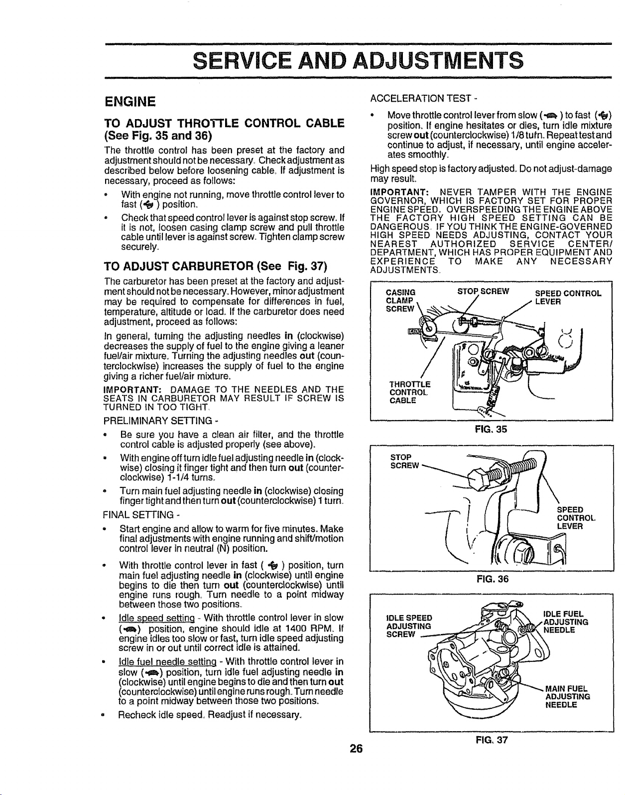
D ADJU
ii HHIll ....... ............ '"'"' " ...........
ENGINE ACCELERATION TEST-
TO ADJUST THROTTLE CONTROL CABLE
(See Fig. 35 and 36)
The throttle control has been preset at the factory and
adjustment shouldnot be necessary, Check adjustmentas
described below before loosening cable If adjustment is
necessary, proceed as follows:
= With engine not running, move throttle control leverto
fast (,_) position.
• Check that speed control lever is against stop screw. If
it is not, loosen casing clamp screw and pull throttle
cable until lever isagainst screw_Tighten clamp screw
securely.
TO ADJUST CARBURETOR (See Fig. 37)
The carburetor has been preset at the factory and adjust-
ment should not be necessary° However, minor adjustment
may be required to compensate for differences in fuel,
temperature, attitude or Ioad_ If the carburetor does need
adjustment, proceed as follows:
tn general, turning the adjusting needles in (clockwise)
decreases the supply of fuel to the engine giving a leaner
fuel/air mixture, Turning the adjusting needles out (coun*
temlockwise) increases the supply of fuel to the engine
giving a richer fueI/air mixture.
IMPORTANT: DAMAGE TO THE NEEDLES AND THE
SEATS IN CARBURETOR MAY RESULT IF SCREW IS
TURNED IN TOO TIGHT,
PRELIMINARY SETTING -
° Be sure you have a clean air filter, and the throttle
control cable is adjusted properly (see above).
• With engine off turn idle fuel adjusting needle in (clock-
wise) closing it finger tight and then turn out (counter-
clockwise) 1-1/4 turns,
o Turn main fuel adjusting needle in (clockwise) closing
finger tight and then turn out (counterclockwise)1 turn.
FINAL SETTING -
• Start engine and allow to warm for five minutes. Make
final adjustmentswith engine running and shift/motion
control lever in neutral (N) position.
° With throttle control lever in fast ( ,_ ) position, turn
main fuet adjusting needle in (clockwise) until engine
begins to die then turn out (counterclockwise) until
engine runs rough, Turn needle to a point midway
between those two positions.
• Ld!espeed settinq _With throttle control lever in slow
(,oh) position, engine should idle at 1400 RPM. if
engine idles too slow or fast, turn idle speed adjusting
screw in or out until correct idle is attained,
• Ldlefuel needle settinq - With throttle control lever in
stow (,€_) position, turn idle fuel adjusting needle in
(clockwise) until engine begins to die and then turn out
(counterclockwise) until engine runs rough. Turn needle
to a point midway between those two positions_
. Recheck idle speed, Readjust if necessary_
° Move throttle control lever from slow (.i_) to fast (,_)
position_ If engine hesitates or dies, turn idle mixture
screw out (counterclockwise) 1/8 tuf'n_ Repeat test and
continue to adjust, if necessary, until engine acceler-
ates smoothly.
High speed stop is factory adjusted_ Do not adjust-damage
may result°
IMPORTANT: NEVER TAMPER WITH THE ENGINE
GOVERNOR, WHICH IS FACTORY SET FOR PROPER
ENGINE SPEED. OVERSPEEDING THE ENGINE ABOVE
THE FACTORY HIGH SPEED SETTING CAN BE
DANGEROUS IF YOU THINK THE ENGINE-GOVERNED
HIGH SPEED NEEDS ADJUSTING, CONTACT YOUR
NEAREST AUTHORIZED SERVICE CENTER/
DEPARTMENT, WHICH HAS PROPER EQUIPMENT AND
EXPERIENCE TO MAKE ANY NECESSARY
ADJUSTMENTS_
CASING STOP SCREW SPEED CONTROL
CLAMP LEVER
THROTTLE
CONTROL
CABLE
FIG, 35
STOP
SPEED
CONTROL,
LEVER
FIG. 36
IDLE FUEL
iDLE SPEED _'_=jef'_.l "_,_./ADJUSTING
ADJUSTING _ _r_k'_ NEEDLE
SCREW "-'"-_____ tb
AIN FUEL
__ _ J ADJUSTING
NEEDLE
FIG, 37
26
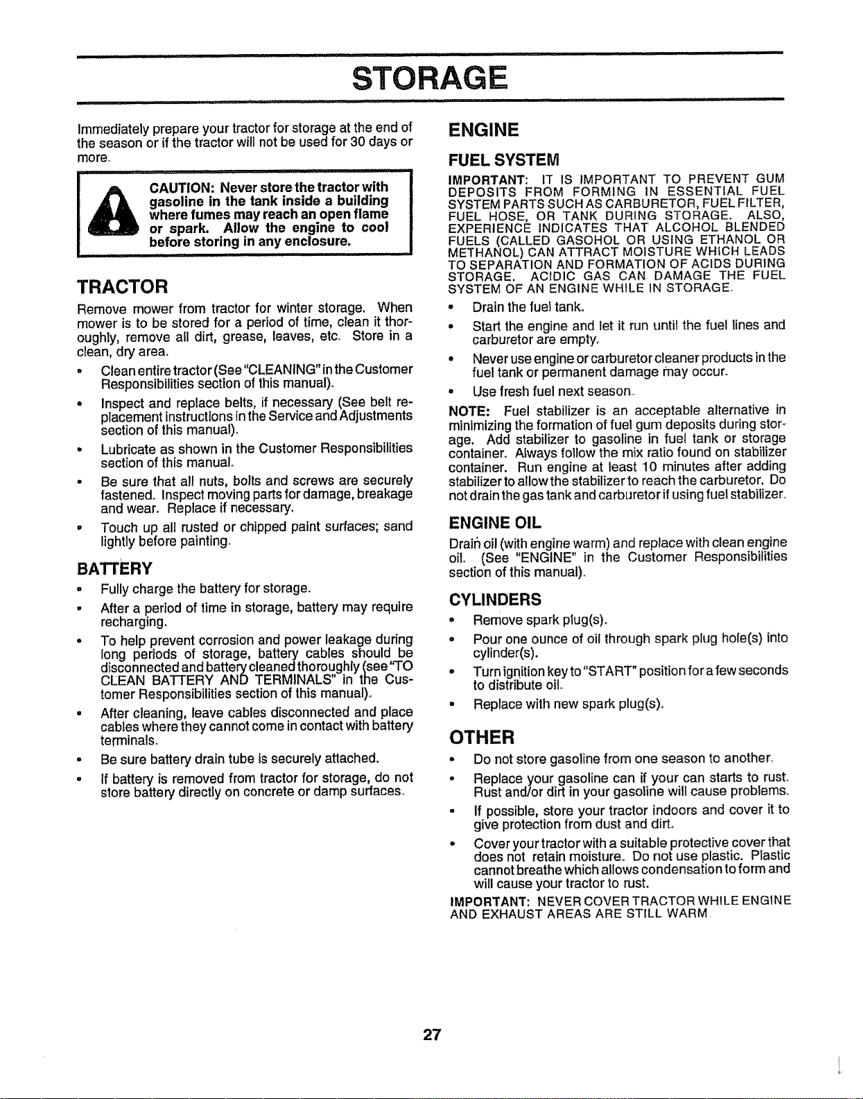
STO
immediately prepare your tractorfor storage at the end of
the season or if the tractor will not be used for 30 days or
noreo
....................... ]'"1[L
CAUTION: Never store the tractor with
gasoline in the tank inside a building
where fumes may reach an open flame
or spark. Allow the engine to cool
before storing in any enclosure,
.... ................ ii, I
TRACTOR
Remove mower from tractor for winter storage. When
mower is to be stored for a period of time, clean it thor-
oughly, remove all dirt, grease, leaves, etc** Store in a
clean, dry area.
• Clean entire tractor (See "CLEANING" in the Customer
Responsibilities section of this manual),.
° Inspect and replace belts, if necessary (See belt re-
placement instructions in the Service and Adjustments
section of this manual).
° Lubricate as shown in the Customer Responsibilities
section of this manual
• Be sure that all nuts, bolts and screws are securely
fastened° Inspect moving parts fordarnage, breakage
and wear. Replace if necessary.
• Touch up all rusted or chipped paint surfaces; sand
lightly before painting
BATTERY
- Fully charge the battery' for storage°
o After a period of time in storage, battery may require
recharging.
° To help prevent corrosion and power leakage during
long periods of storage, battery cables should be
disconnected and battery cleaned thoroughly (see"TO
CLEAN BATTERY AND TERMINALS" in the Cus-
tomer Responsibilities section of this manual).
° After cleaning, leave cables disconnected and place
cables where they cannot come in contact with battery
terrninals.
• Be sure battery drain tube tssecurely attached.
• If battery is removed from tractor for storage, do not
store battery directly on concrete or damp surfaces_
ENGINE
FUEL SYSTEM
IMPORTANT: IT IS IMPORTANT TO PREVENT GUM
DEPOSITS FROM FORMING IN ESSENTIAL FUEL
SYSTEM PARTSSUCH AS CARBURETOR, FUEL FILTER,
FUEL HOSE, OR TANK DURING STORAGE. ALSO,
EXPERIENCE INDICATES THAT ALCOHOL BLENDED
FUELS (CALLED GASOHOL OR USING ETHANOL OR
METHANOL) CAN ATTRACT MOISTURE WHICH LEADS
TO SEPARATION AND FORMATION OF ACIDS DURING
STORAGE, ACIDIC GAS CAN DAMAGE THE FUEL
SYSTEM OF AN ENGINE WHILE tN STORAGE.
= Drainthe fuettank.
• Start the engine and let it run until the fuel lines and
carburetor are empty.
• Never use engine or carburetor cleaner products in the
fuel tank or permanent damage may occur.
• Use fresh fuel next season.,
NOTE: Fuel stabilizer is an acceptable alternative in
minimizing the formation of rue! gum deposits during stor_
age. Add stabilizer to gasoline in fuel tank or storage
container. Always follow the mix ratio found on stabilizer
container. Run engine at least 10 minutes after adding
stabilizerto allow the stabilizer to reach the carburetor. Do
not drain the gas tank and carburetor if using fuel stabilizer_.
ENGINE OIL
Drain oil (with engine warm) and replace withclean engine
oil (See "ENGINE" in the Customer Responsibilities
section of this manual)_
CYLINDERS
• Remove sparkplug(s).
o Pour one ounce of oil through spark plug hole(s) into
cylinder(s).
o Turn ignition key to "STAR'I" position for a few seconds
to distribute oil
- Replace with new spark plug(s)o
OTHER
• Do not store gasoline from one season to another,
• Replace your gasoline can if your can starts to rust°
Rust and/or dirt in your gasoline will cause problems°
° If possible, store your tractor indoors and cover it to
give protection from dust and dirt,
• Cover your tractor with a suitable protective cover that
does not retain moisture,, Do not use plastic. Plastic
cannot breathe which allows condensation to form and
will cause your tractor to rust,
IMPORTANT: NEVER COVER TRACTOR WHILE ENGINE
AND EXHAUST AREAS ARE ST{LL WARM.
27

PROBLEM
lUlll i iiiiiii i1:1 iiilu
Will not start
Hard to start
Engine will not turn over
Engine clicks but will not
start
Loss of power
Excessive vibration
........... :....... i, lUl ...... :- , ii iii i i i
:....... :::: I ' I ........... II I IIIJl '!1111111
TROUBLESHOOTING POINTS
CAUSE
1_ Outoffuel.
2. Engine not =CHOKED" properly,
3, Engine flooded,
4,. Bad spark plug,
5. Dirty air filter;
6. Dirtyfuel filter
7. Water in fuel_
8, Loose or damaged widng.
9. Carburetor out of adjustment,
10 Engine valves out of adjustment,.
1, Dirty air filter.
2, Bad spark plug
3 Weak or dead battery,.
4 Dirty fuel filter,
5 State or dirty fuel.
6 Loose or damaged wiring°
7 Carburetor out of adjustment.
8, Engine valves out of adjustment
1, Clutch/brake pedal nat depressed,
2. Attachment clutch is engaged.
3, Weak or dead battery,
4 Blown fuse
5 Corroded battery terminals
6 Looseor damagedwidng,
7 Faulty ignition switch
8, Faulty solenoid or starter_
9 Faulty operator presence switch(es).
I, Weak or dead battery,
2, Corroded battery terminals,
3. Loose or damaged wiring.
4 Faulty solenoid or starter,,
1. Cutting too much grass/too fast,.
2. Throttle in "CHOKE" position.
3, Build-up of grass, leaves and !rash under mower,
4,, Dirtyair filter,
5, Low oil level/dirty oiL
6. Faulty spark plug
7, Dirty fuel filler,
8 Stale or dirty fuel
9. Water in fuel.
10, Spark plug wire loose,
11 Dirty engine air screen/fins
12o Dirty/clogged muffier.
13. Loose or damaged wiring,
t4. Carburetor out of adjustment,,
15_ Engine valves out of adjustment.
1. Worn, bent or Ioose blade,
2. Bent blade mandre!.
3 Loose/damaged part(s)..
CORRECTION
..... :- i i iii i ii,UlUll ......... : .... tl, ii
I,, Fill fuel tank.
2. See "TO START ENGINE" in Operation section..
3. Wait several minutes before attempting to start,
4_ Replace spark plug,
5. Ciean/replace air filter,.
6, Replace fuel filter,
7. Drain f,Jel tank and carburetor, refltl tank with fresh
gasoline and replace fuel filter
8, Check all widng,.
9,. Contact an authorized service centerldepartment.
10, Contact an authorized service oenteddepartmenL
I_ Clear/replace air filter,.
2. Replace spark plug,
3,. Recharge or repface battery
4. Repiace fuel filter,
5. Drain flJeItank and refiliwith fresh gasoline.
6, Check atl wiring.
7, Contact an authorized service centeddepartment.
8 Contact an authorized service centertdepartment.
1. Depress ciutchJbraka pedal°
2. Disengage attachment clutch,
3. Recharge or replace battery.
4. Replace fuse,
5_ Clean battery terminals,
6. Check a!l wtdng,
7, Check/replace ignition switch
8_ ChecPJreplace solenoid or starteL
9. Contact an authorized service centertdepartment.
1. Recharge or repface battery,,
2 Clean battery terrninals,
3, Checkall wldng
4. Check/replace solenoid or starter.
1,, Set in "Higher Cut" position/reduce speed,
2. Adjust throttle control
3o Clean underside of mower housing.
4o Clean/replace air fitter,
5_ Check oil leveffchange oil.
6. clean and regap or change spark plug
7, Replace fuel filter.
8,, Drain fuel tank and refill with fresh gasoline.
9. Drain fuel tank and carburetor, refili tank with fresh
gasoline and replace fuel filter,.
10 Connect and tighten spark plug wire.
tt, Clean engine air screenifins_
12. Clean/replace muffler,.
13, Check all wtdng.
!4. Contact an authodzed service centertdepartmento
15 Contact an authorized service center/department
1 Replace blade Tighten blade bott
2, Replace blade mandrel
3, Tighten loose part(s). Replace damaged parts,
28

PROBLEM
Engine continues to run
when operator leaves seat
with attachment clutch
engaged
Poor cut - uneven
Mower blades will not
rotate
Poor grass dlscharge
Headlight(s) not working
(If so equipped)
Battery wtll not charge
Engine "backfires"
when turning engine
"OFF"
TRO COTING
POINTS
CAUSE
1, Faulty operator_safety presence controlsystem
1, Worn, bent or loose blade°
2. Mower deck not level,,
3. Buildup of grass, leaves, and trash under mower°
4. Bent blade mandrel°
5, Clogged m;ower deck vent holes from buildup of
grass, leaves, and trash around mandrels
1, ObsmJct_on fn clutch mechanism,
2, Worn/damaged mower ddve bait.
3. Frozen Idler pulley.,
4. Frozen blade mandrel.
t. Engine speed too slow.
2, Travel speed too fast,,
3, Wet grass,
4, Mower deck not level,
5, Lowluneven tire air pressure.
6, Worn, bent or loose blade.
7, Buildup of grass, leaves and trash under mower.
8, Mower d_ive belt worn.
9. Blades improperly installed.
10o Improper blades used.
11. Clogged mower deck vent holes from buildup of
grass, leaves, and trash around mandrels.,
1. Switch ls "OFF"_
2. Butb(s) burned out,.
3, Fautty itght switch.
4_ Loose or damaged wiring.
5_ Blown fuse,
1o Bad battery cell(s),
2. Poor cable connections,
3. Faulty regulator (if so equipped).
4,, Faulty alternator,
CORRECTION
1. Check wiring, switches and connections. If not
corrected, contact an authorized service center/
department.
t. Replace blade., Tighten blade boil
2. Level mower deck.,
3_ CIean underside of mower housing.
4. Replace blade mandrel.
5. Clean around mandrets to open vent holes.
1, Remove obstruction,
2. Replace mower drive belt.
3, Replace idler pulley,
4, Replace blade mandrel,
1. Place throttle control in "FAST" position,
2° Shift to slower speed,
3, Allow grass to drybefore mowing.
4. Level mower deck
5. Check tires for proper air pressure,
6, Replacetsharpen blade, Tighten blade bolt,
7. Clean underside of mower housing,
B_ Replace mower drive belt,
9. Reinstall blades sharp edge down.
10, Replace with blades listed in this manual.,
11, Clean around mandrels to open vent holes,,
1, Turn switch "ON",
2. Replace bulb(s)
3., ChecWreptace light switch.
4., Check wiring and connections,,
5, Replace fuse,
1. Replace battery.,
2, Check/clean all connections
3. Replace regulator
4, Replace alternator,
Move throttle control to "SLOW" position and altow
to idle for 30 seconds before stopping engine.
Engine throttle control not set at =SLOW"
positionfor 30 seconds before stopping engine.
29

E NOTES
i .i illll ii, .....
30
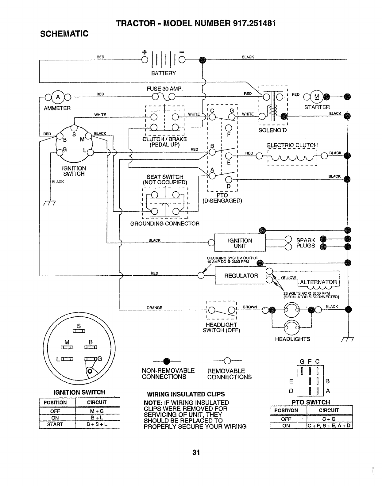
SCHEMATIC
TRACTOR - MODEL NUMBER 917.251481
RED
ORANGE
CHARGING SYSTEM OUTPUT
15 AMP 13(3@ 3600 RPM A
REGULATOR
1 I
I ! BROWN
1 I
HEADLIGHT
SWITCH (OFF)
_EL_OWL_T_
2_voL__o,_3_00RPM
_,_EOULATO.D,SCO,,N_OT_O)
BLACK
HEADLIGHTS
D
D
D
:D
F7
IGNITION SWITCH
POSITION CIRCUIT
OFF M + G
ON B+L __
START B + S + L
--0--
NON-REMOVABLE
CONNECTIONS
REMOVABLE
CONNECTIONS
WIRING INSULATED CLIPS
NOTE" IF WIRING INSULATED
CLIPS WERE REMOVED FOR
SERVICING OF UNIT, THEY
SHOULD BE REPLACED TO
PROPERLY SECURE YOUR WIRING
GFC
E _IB
o _UA
PTO SWITCH
PosmoN CIRCUIT
..............oFF....._.........€÷GII1-11i
ON C+FIB+E,A+D!
31
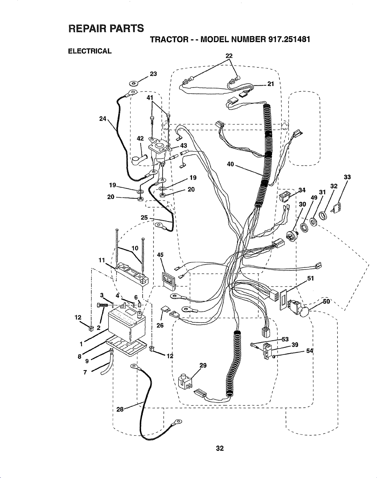
REPAIR PARTS
ELECTRICAL
TRACTOR -- MODEL NUMBER 917.251481
22
\
21
I
1 /
I l
I
! i
t 1
19
\ /
2O
29
\
.... 41 31
I
32
\
f
I
I
39 5_
I
1
I
!
!
!
!
t
/
I
f
|
/
T
I
I
!
32
33
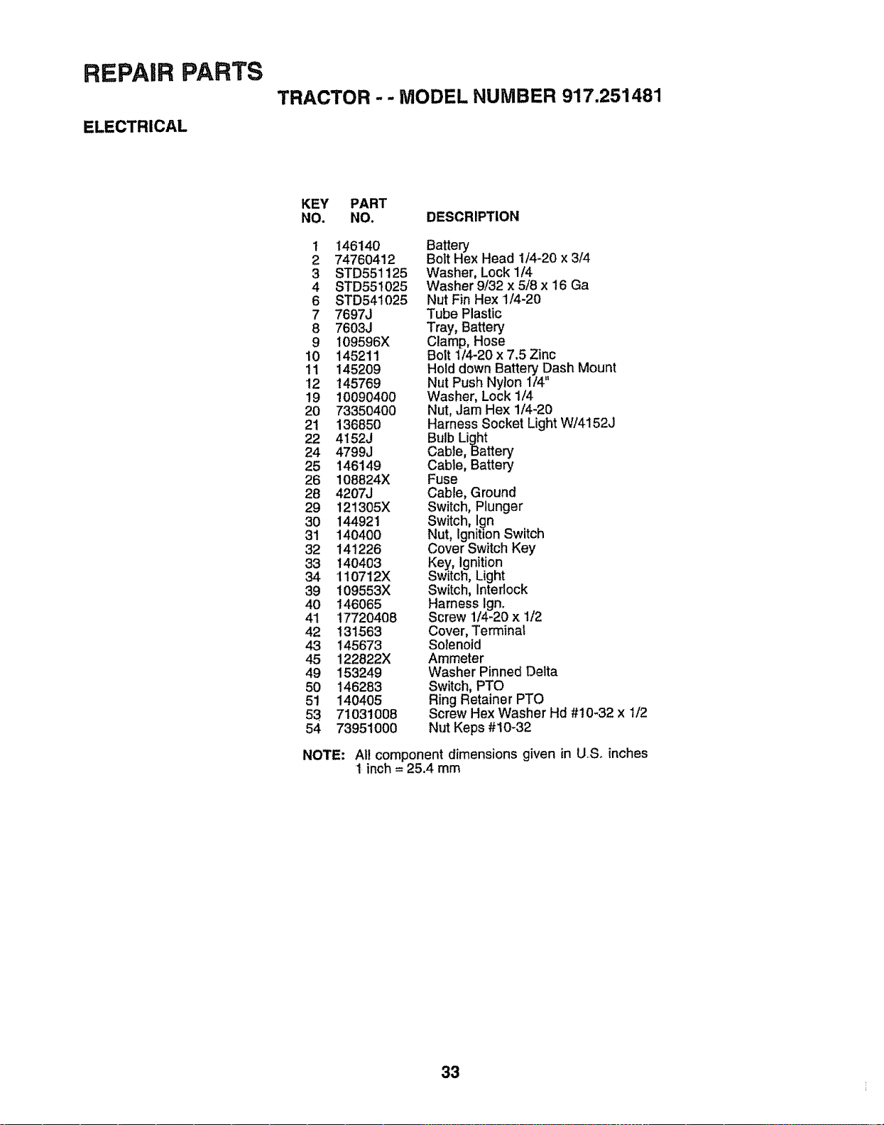
REPAIR PARTS
ELECTRICAL
TRACTOR -- MODEL NUMBER 917.251481
KEY PART
NO. NO, DESCRIPTION
t 146140 Battery
2 74760412 Bolt Hex Head 1/4-20 x 3/4
3 STD551125 Washer, Lock 1/4
4 STD551025 Washer 9/32 x 5/8 x 16 Ga
6 STD541025 Nut Fin Hex 1/4-20
7 7697J Tube Plastic
8 7603J Tray, Battery
9 109596X Clamp, Hose
10 145211 Bolt 1/4-20 x 7.5 Zinc
11 145209 Hold down Battery Dash Mount
12 145769 Nut Push Nylon I/4"
19 10090400 Washer, Lock 1/4
20 73350400 Nut, ,Jam Hex 1/4-20
21 136850 Harness Socket Light W/4152J
22 4152J Bulb Light
24 4799J Cable, Batten]
25 146149 Cable, Battery
26 108824X Fuse
28 4207J Cable, Ground
29 121305X Switch, Plunger
30 144921 Switch, l_n
31 140400 Nut, Ignition Switch
32 141226 Cover Switch Key
33 140403 Key, Ignition
34 110712X Switch, Light
39 109553X Switch, Interlock
40 t46065 Harness Ign.
41 17720408 Screw 1/4-20 x 1/2
42 131563 Cover, Terminal
43 145673 Solenoid
45 122822X Ammeter
49 153249 Washer Pinned Delta
50 146283 Switch, PTO
51 140405 Ring Retainer PTO
53 71031008 Screw Hex Washer Hd #10-32 x 1/2
54 73951000 Nut Keps #10-32
NOTE: All component dimensions given in U..Soinches
t inch = 25.4 mm
33
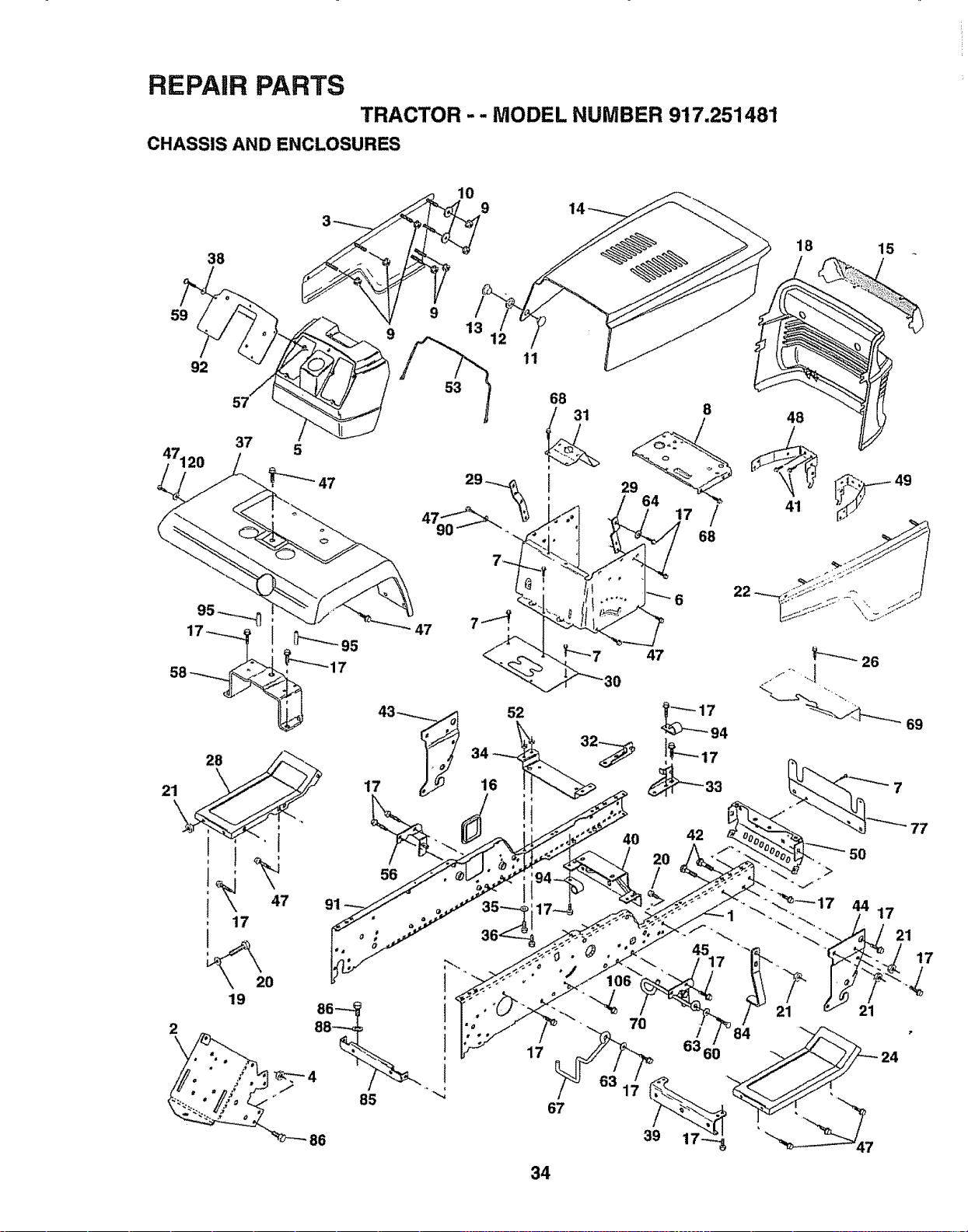
REPAIR PARTS
TRACTOR - - MODEL NUMBER 917.251481
CHASSIS AND ENCLOSURES
38
59
92
47120
57
37
10
9
53
11
47 7_
, 17
19
2
56
17
/
67
7O
86
68
47
42
18 15
48
41
V'_.... 26
,J
69
34
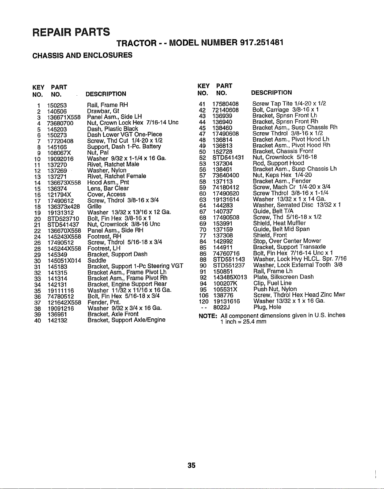
REPAIR PARTS
TRACTOR -- MODEL NUMBER 917.251481
CHASSIS AND ENCLOSURES
KEY PART KEY PART
NO, NO. DESCRIPTION NO. NO. DESCRIPTION
1 150253 Rail, Frame RH 41 t7580408
2 140506 Drawbar, Gt 42 72140608
3 136671X558 Panel Asm., Side LH 43 136939
4 73680700 Nut, Crown Lock Hex 7/16-14 Unc 44 136940
5 t45203 Dash, Plastic Black 45 138460
6 150273 Dash Lower VGT One-Piece 47 17490608
7 17720408 Screw, Thd Cut 1/4_20 x 1/2 48 136814
8 145166 Support, Dash 1-Pc. Battery 49 136813
9 108067X Nut, Pal 50 !52728
10 19092016 Washer 9/32x 1-1/4x 16 Gao 52 STD541431
11 137270 Rivet, Ratchet Male 53 t37304
12 137269 Washer, Nylon 56 138461
13 137271 Rivet, Ratchet Female 57 73640400
14 136673X558 Hood Asm., Pnt 58 137113
15 136374 Lens, Bar Clear 59 74180412
16 121794X Cover, Access 60 17490620
17 17490612 Screw, Thdrol 3/8-16 x3/4 63 19131614
18 136373x428 Gdlle 64 144283
19 19131312 Washer 13/32x 13/16x 12 Ga. 67 140737
20 STD523710 Bolt, Fin Hex 3/8-16 x 1 68 17490508
21 STD541437 Nut, Crownlock 3/8-16 Unc 69 153991
22 136670X558 PanelAsm., Side RH 70 137159
24 145243X558 Footrest, RH 77 137308
26 17490512 Screw, Thdrof 5/16-18 x 3/4 84 142992
28 145244X558 Footrest, LH 85 144911
29 145349 Bracket, Support Dash 86 74760716
30 145051X014 Saddle 88 STD551143
31 145183 Bracket, Support 1-Pc Steering VGT 90 STD551237
32 141315 Bracket Asmo, Frame Pivot Lh 91 150851
33 141314 Bracket Asm., Frame Pivot Rh 92 143485X013
34 142131 Bracket, Engine Support Rear 94 100207K
35 19111116 Washer 11/32 x 11/16 x 16 Ga° 95 105531X
36 74780512 Bolt, Fin Hex 5/16-18 x 3/4 106 138776
37 121642X558 Fender, PnL t20 19131616
38 19091216 Washer 9/32x3/4x 16Ga. -- 8022J
39 136961 Bracket, Axle Front NOTE:
40 142132 Bracket, Support AxlelEnglne
Screw Tap Tite 1/4-20 × 1/2
Bolt, Carriage 3/8-16 x 1
Bracket, Spnsn Front Lh
Bracket, Spnsn Front Rh
Bracket Asm. Susp Chassis Rh
Screw Thdrol 3/8-16 x 1/2
Bracket Asmo, Pivot Hood Lh
Bracket Asm., Pivot Hood Rh
Bracket, Chassis Front
Nut, Crownlock 5/16-18
Rod, Support Hood
Bracket Asm, Susp Chassis Lh
Nut, Keps Hex 1/4-20
Bracket Asm,, Fender
Screw, Mach Cr 1/4-20 x 3/4
Screw Thdrol 3/8-16 x 1-1/4
Washer 13/32 x 1 × 14 Ga.
Washer, Serrated Disc t3/32 x 1
Guide, Belt T/A
Screw, Thd 5/16-18 x 1/2
Shield, Heat Muffler
Guide, Belt Mid Span
Shield, Front
Stop, Over Center Mower
Bracket, Support Transaxle
Bolt, Fin Hex 7/16-14 Unc x 1
Washer, Lock Hvy HLCLo Spr. 7/16
Washer, Lock External Tooth 3/8
Rail, Frame Lh
Plate, Silkscreen Dash
Clip, Fuel Line
Push Nut, Nylon
Screw, Thdrol Hex Head Zinc Mwr
Washer 13/32 x I X 16 Ga,
Plug, Hole
All component dimensions given in US. inches
1 inch = 25.4 mm
35
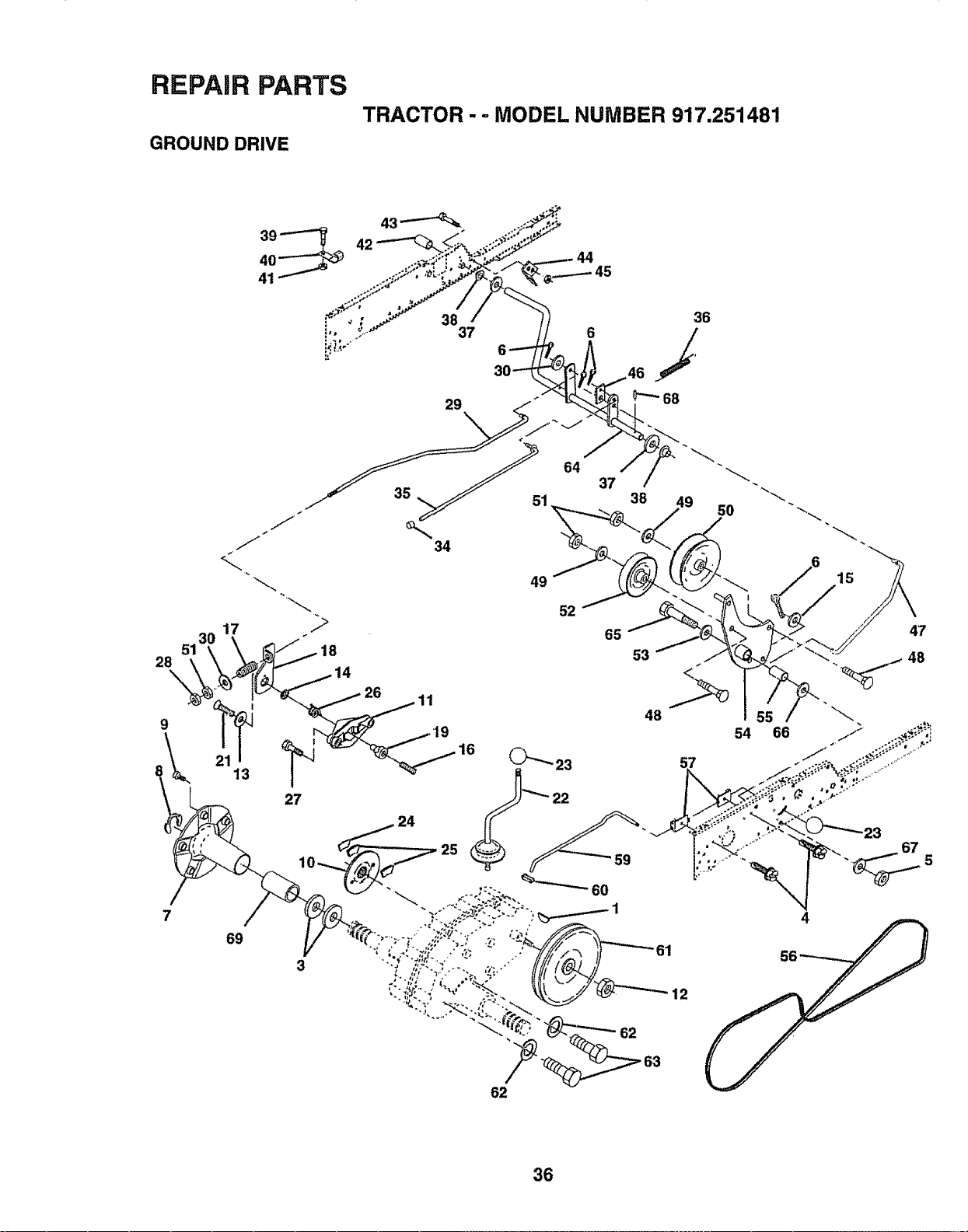
REPAIR PARTS
GROUND DRIVE
TRACTOR
- " MODEL NUMBER 917.251481
36
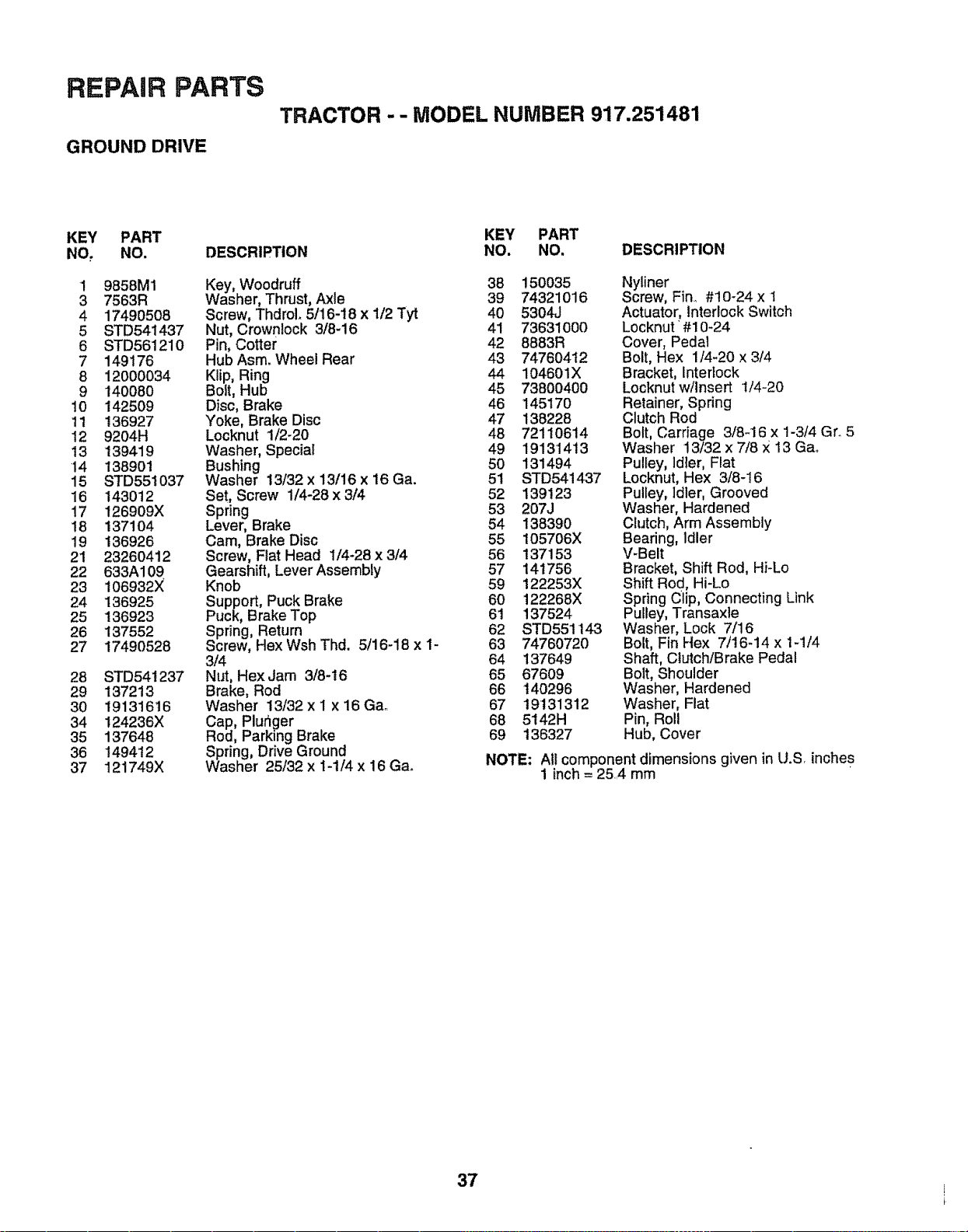
REPAIR PARTS
GROUND DRIVE
TRACTOR - - MODEL NUMBER 917.251481
KEY PART
NO, NO.
1 9858M1
3 7563R
4 17490508
5 STD541437
6 STD561210
7 149176
8 12O00034
9 140080
10 142509
11 136927
12 9204H
13 139419
14 138901
15 STD551037
16 143012
17 126909X
18 137104
19 136926
21 2326O412
22 633A109
23 106932X
24 136925
25 136923
26 137552
27 17490528
28 STD541237
29 137213
30 19131616
34 124236X
35 137648
36 149412
37 121749X
DESCRIPTION
Key, Woodruff
Washer, Thrust, Axle
Screw, ThdroL 5/16-18 x 1/2 Tyt
Nut, Crownlock 3/8-16
Pin, Cotter
Hub Asm. Wheel Rear
Klip, Ring
Bolt, Hub
Disc, Brake
Yoke, Brake Disc
Locknut 1/2-20
Washer, Special
Bushing
Washer 13/32 x 13/16 x 16 Ga.
Set, Screw 1/4-28 x 3/4
Spring
Lever, Brake
Cam, Brake Disc
Screw, Flat Head 1/4-28 x 3/4
Gearshift, Lever Assembly
Knob
Support, Puck Brake
Puck, Brake Top
Spring, Return
Screw, Hex Wsh Thd. 5/16-18 x I-
3/4
Nut, HexJam 3/8-16
Brake, Rod
Washer 13/32 x I x 16 Gao
Cap, Plur_ger
Rod, Parking Brake
Spring, Drive Ground
Washer 25/32 x 1-1/4 x 16 Ga°
KEY PART
NO. NO, DESCRIPTION
38 150035 Nyliner
39 74321016 Screw, Fin., #10-24 x 1
40 5304J Actuator, Interlock Switch
41 73631000 Locknut #10-24
42 8883R Cover, Pedal
43 74760412 Bolt, Hex 1/4_20 x 3/4
44 104601X Bracket, Interlock
45 73800400 Locknut w/insert 1/4-20
46 145170 Retainer, Spring
47 138228 Clutch Rod
48 72110614 Bolt, Carriage 3/8-16 x 1-3/4 Gr. 5
49 19131413 Washer 13/32 x 7/8 × 13 Gao
50 131494 Pulley, ldier, Fiat
51 STD541437 Locknut, Hex 3/8-16
52 139123 Pulley, Idler, Grooved
53 207J Washer, Hardened
54 138390 Clutch, Arm Assembly
55 105706X Bearing, Idler
56 137153 V-Belt
57 141756 Bracket, Shift Rod, Hi-Lo
59 122253X Shift Rod, Hi-Lo
60 122268X Spring Clip, Connecting Link
61 137524 Pulley, Transaxte
62 STD551143 Washer, Lock 7/16
63 74760720 Bolt, Fin Hex 7/16-14 x 1-1/4
64 137649 Shaft, Clutch/Brake Pedal
65 67609 Bolt, Shoulder
66 t40296 Washer, Hardened
67 19'131312 Washer, Fiat
68 5142H Pin, Roll
69 136327 Hub, Cover
NOTE: Al! component dimensions given in U.S inches
1 inch = 25,4 mm
37
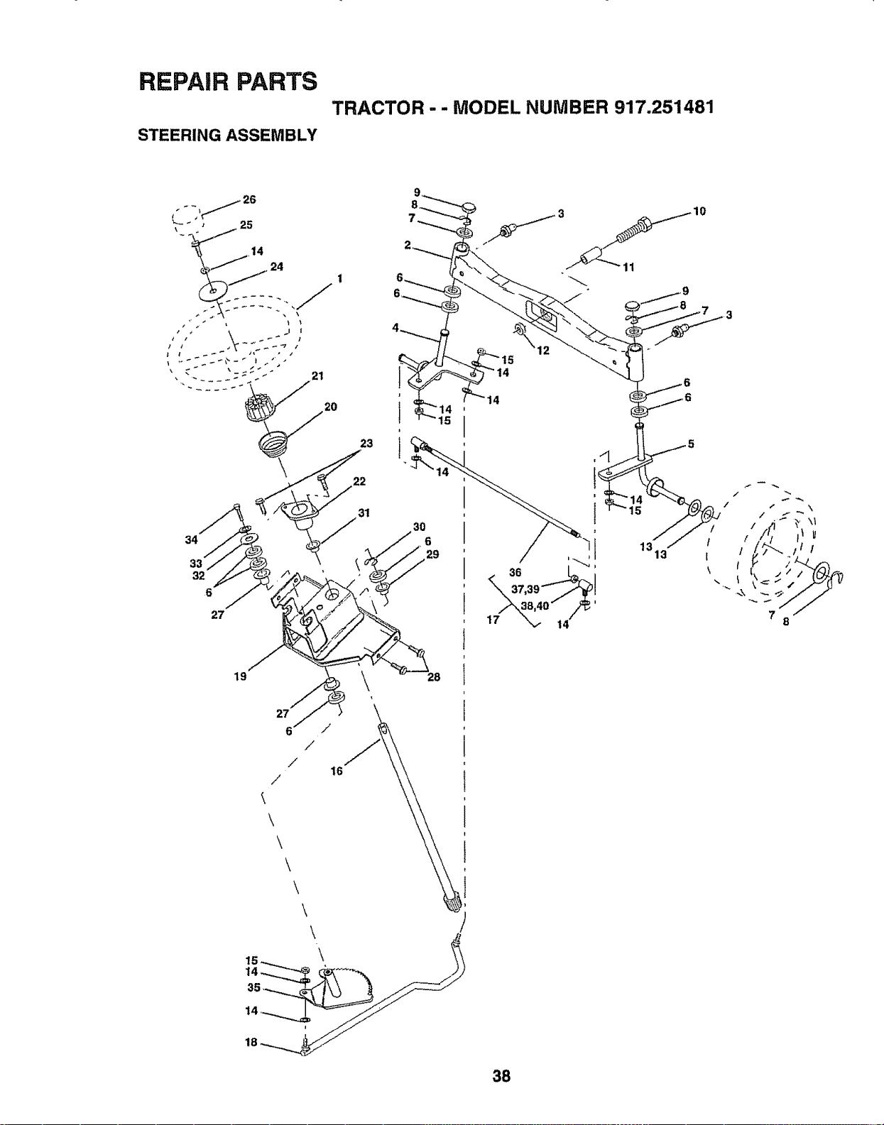
REPAIR PARTS
STEERING ASSEMBLY
TRACTOR - - MODEL NUMBER 917,251481
34
33
32
6
21
27
23
,31
t
15
19
27
6 f
/
f
16
/
\
\
\
\
\
\
38
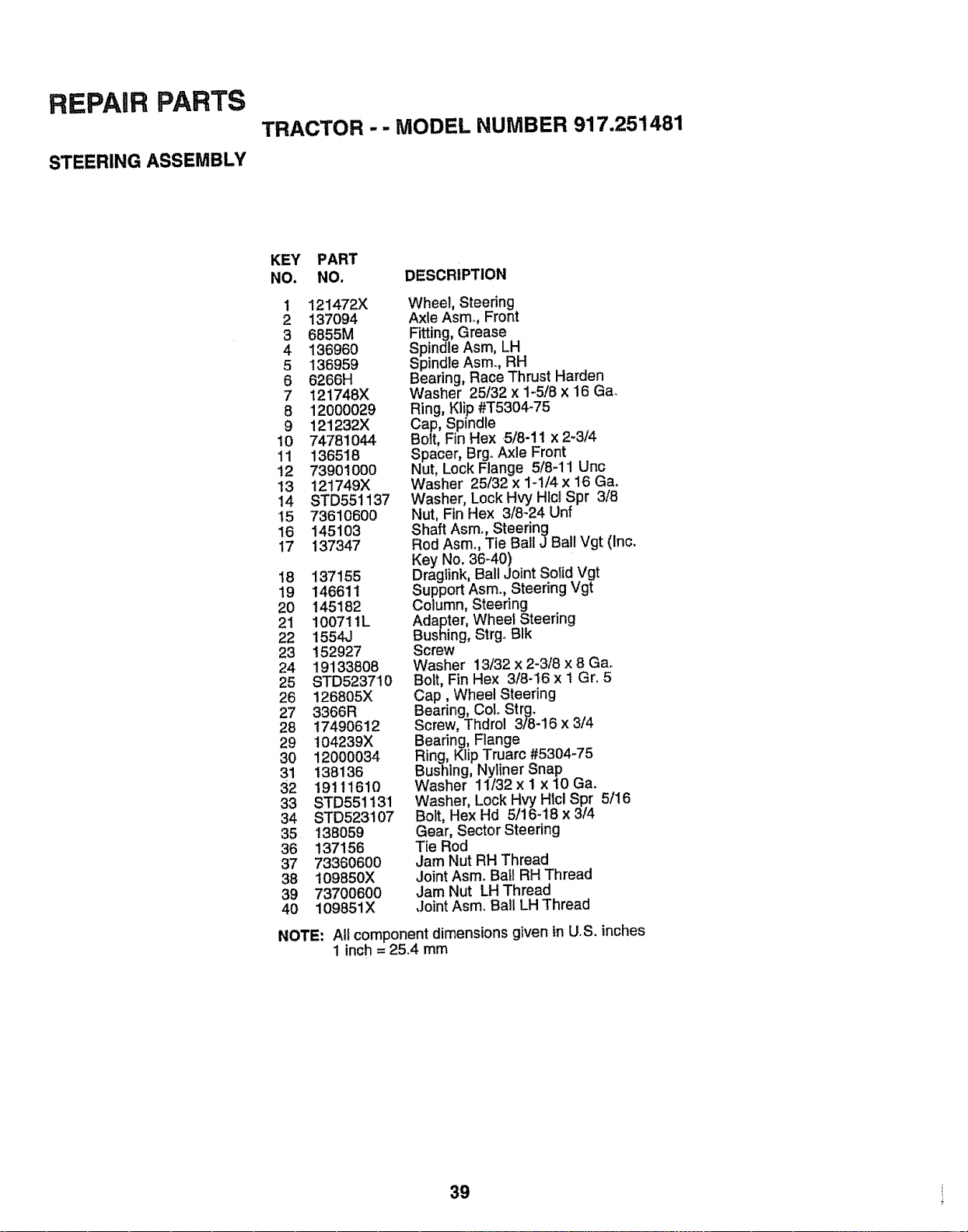
REPAIR PARTS
STEERING ASSEMBLY
TRACTOR - - MODEL NUMBER 917.251481
KEY PART
NO. NO. DESCRIPTION
1 121472X
2 137094
3 6855M
4 136960
5 136959
6 6266H
7 121748X
8 12000029
9 121232X
10 74781044
11 136518
12 739O1OO0
13 121749X
14 STD551137
15 73610600
16 145103
17 137347
t8 137155
19 146611
20 145182
21 100711L
22 1554J
23 152927
24 19133808
25 STD523710
26 126805X
27 3366R
28 17490612
29 t04239X
30 12000034
31 138136
32 19111610
33 STD551131
34 STD523t07
35 138059
36 137156
37 733606O0
38 109850X
39 73700600
4O 109851X
Wheel, Steering
Axle Asmo, Front
Fitting, Grease
Spindle Asm, LH
Spindle Asm., RH
Beating, Race Thrust Harden
Washer 25/32 x 1-5/8 x 16 Ga.
Ring, Klip #T5304-75
Cap, Spindre
Bolt, Fin Hex 5/8-11 x 2-3/4
Spacer, BrgoAxle Front
Nut, Lock Flange 5/8-11 Unc
Washer 25/32 x 1-1/4x 16 Ga.
Washer, Lock Hvy Hlcl Spr 3/8
Nut, Fin Hex 3/8-24 Unf
Shaft Asm., Steering
Rod Asm., Tie Bali J Ball Vgt (Inc.
Key No. 36-40)
Draglink, Ball Joint Solid Vgt
Support Asm, Steering Vgt
Column, Steering
Adapter, Wheel Steering
Bushing, Strgo BIk
Screw
Washer 13/32 x 2-3/8 x 8 Gao
Bolt, Fin Hex 3/8-16 x ! Gr. 5
Cap, Wheel Steering
Bearing, CoL Strg.
Screw, Thdrol 3/8-16 x 3/4
Bearing, Flange
Ring, Klip Truarc #5304-75
Bushing, Nyliner Snap
Washer 11/32 x 1 x 10 Ga.
Washer, Lock Hvy Hlcl Spr 5/16
Bolt, Hex Hd 5/16-18 x 3/4
Gear, Sector Steering
Tie Rod
Jam Nut RH Thread
Joint Asm. Ball RH Thread
Jam Nut LH Thread
,JointAsm. Bail LH Thread
NOTE: All component dimensions given in U.S. inches
1 inch = 25.4 mm
39
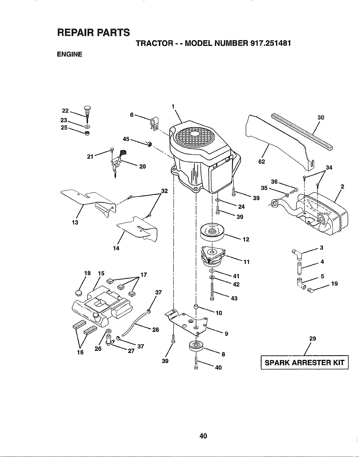
REPAIR PARTS
ENGINE
TRACTOR - - MODEL NUMBER 917.251481
18 15
16
20
32
14
17
39
9
24
39
12
11
41
42
43
30
62
34
0J4
_j_5
29
/
I SPARK ARRESTER KIT ]
4O
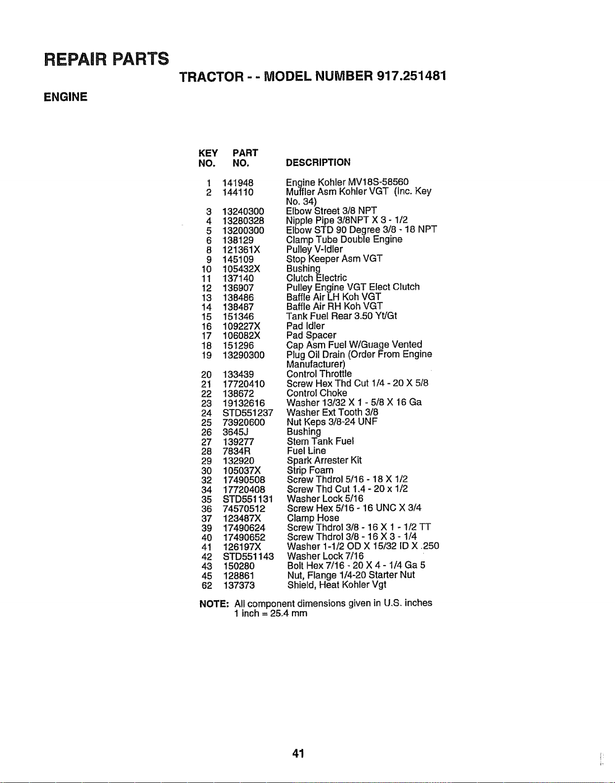
REPAIR PARTS
ENGINE
TRACTOR - - MODEL NUMBER 917.251481
KEY PART
NO. NO. DESCRIPTION
1 141948
2 144110
3 1324O300
4 13280328
5 1320030O
6 138129
8 121361X
9 145109
10 105432X
11 137140
12 136907
13 138486
14 138487
15 151346
16 109227X
17 106082X
18 151296
19 13290300
20 133439
21 17720410
22 138672
23 19132616
24 STD55i237
25 73920600
26 3645J
27 139277
28 7834R
29 132920
3O 105037X
32 17490508
34 177204O8
35 STD551131
36 74570512
37 123487X
39 17490624
40 17490652
41 126197X
42 STD551143
43 150280
45 128861
62 137373
Engine Kohler MV18S-58560
Muffler Asm Kohler VGT (Inc. Key
No, 34)
Elbow Street 3/8 NPT
Nipple Pipe 3/8NPT X 3 - 1/2
Elbow STD 90 Degree 3/8 - 18 NPT
Clamp Tube Double Engine
Pulley V-Idler
Stop Keeper Asm VGT
Bushing
Clutch Electric
Pulley Engine VGT Elect Clutch
Baffle Air LH Koh VGT
Baffle Air RH Koh VGT
Tank Fuel Rear &50 Yt/Gt
Pad Idler
Pad Spacer
Cap Asm Fuel W/Guage Vented
Plug Oil Drain (Order From Engine
Manufacturer)
Control Throttle
Screw Hex Thd Cut 1/4 - 20 X 5/8
Control Choke
Washer 13/32 X 1 - 5/8 X 16 Ga
Washer Ext Tooth 3/8
Nut Keps 3/8-24 UNF
Bushing
Stem Tank Fuel
Fuel Line
Spark Arrester Kit
Strip Foam
Screw Thdrol 5/16- 18 X 1/2
Screw Thd Cut 1.4 - 20 x 1/2
Washer Lock 5/16
Screw Hex 5116- 16 UNC X 3/4
Clamp Hose
Screw Thdrol 3/8 - 16 X 1 - t/2 TT
Screw Thdrol 3/8 - 16 X 3 - 1/4
Washer 1-1/20D X 15/32 ID X .250
Washer Lock 7/16
Bolt Hex 7/16 - 20 X 4 - 1/4 Ga 5
Nut, Flange 1/4-20 Starter Nut
Shield, Heat Kohler Vgt
NOTE: All component dimensions given in U,S. inches
1 inch = 2&4 mm
41
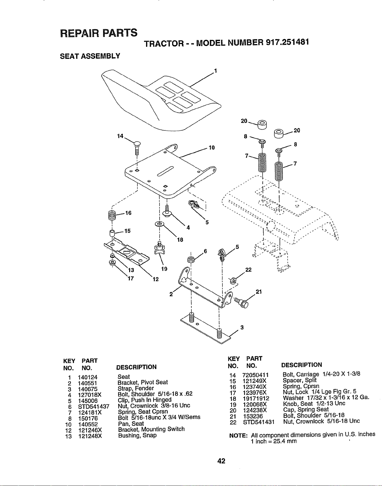
REPAIR PARTS
SEAT ASSEMBLY
TRACTOR - - MODEL NUMBER 917.251481
i[ :'
21
KEY
NO.
1
2
3
4
5
6
7
8
10
12
13
PART
NO,
140124
140551
140675
127018X
145008
8TD541437
124181X
150176
140552
121246X
121248X
DESCRIPTION
Seat
Bracket, Pivot Seat
Strap, Fender
Bolt, Shoulder 5/16-18 x ..62
Clip, Push In Hinged
Nut, Crownlock 3/8-16 Unc
Spring, Seat Cprsn
Bolt 5/16-18unc X 3/4 W/Sems
Pan, Seat
Bracket, Mounting Switch
Bushing, Snap
KEY PART
NO. NO.
14 72050411
15 121249X
16 123740X
17 123976X
18 19171912
19 120068X
20 124238X
21 153236
22 8TD541431
DESCRIPTION
Bolt, Carriage 1/4-20 X 1-3/8
Spaceh Split
Spring, Cprsn
Nut, Lock 1/4 Lge Fig Gr. 5
Washer 17/32 x 1-3/16 x 12 Ga.
Knob, Seat 1/2-13 Unc
Cap, Spring Seat
Bolt, Shoulder 5/16-18
Nut, Crownlock 5/16-18 Unc
NOTE: All component dimensions given in U..S_inche
1 inch = 25°4 mm
42
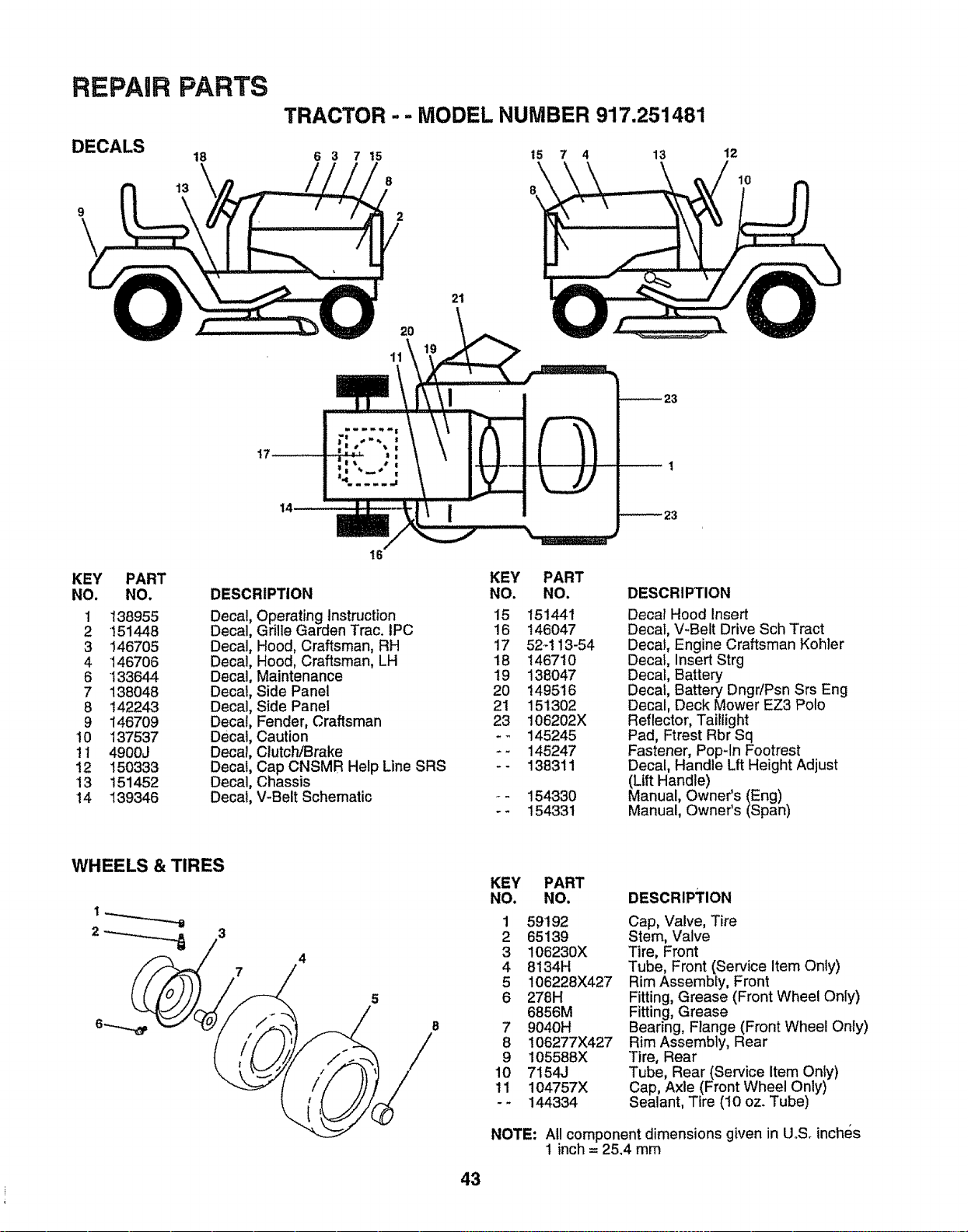
REPAIR
DECALS
PARTS
18
13
TRACTOR - - MODEL NUMBER 917.251481
6 3 7 15 t5 7 4 13
8
2
12
10
2t
20
14
KEY PART
NO. NO.
1 138955
2 151448
3 146705
4 146706
6 133644
7 138048
8 142243
9 146709
10 137537
!t 4900J
12 150333
13 151452
14 139346
16
DESCRIPTION
Decal Operating Instruction
Decal Grille Garden Trac. IPC
Decal Hood, Craftsman, RH
Decal Hood, Craftsman, LH
Decal Maintenance
Decal Side Panel
Decal Side Panel
Decal Fender, Craftsman
Decal Caution
Decal Clutc!-dBrake
Decal Cap CNSMR Help Line SRS
Decal Chassis
Decal V-Belt Schematic
KEY PART
NO. NO.
15 151441
16 146047
17 52-113-54
18 146710
19 138047
20 149516
21 151302
23 106202X
-_ 145245
-- 145247
-- 138311
154330
154331
DESCRIPTION
Decal Hood Insert
Decal, V-Belt Drive Sch Tract
Decal, Engine Craftsman Kohler
Decal, Insert Strg
Decal, Battery
Decal, Battery DngdPsn Srs Eng
Decal, Deck Mower EZ3 Polo
Reflector, Taillight
Pad, Ftrest Rbr Sq
Fastener, Popqn Footrest
Decal, Handle Lft Height Adjust
(Lift Handle)
Manual, Owner's (Eng)
Manual, Owner's (Span)
WHEELS & TIRES
7
4
5
B
/
43
KEY PART
NO. NO.
1
2
3
4
5
6
7
8
9
10
tl
59192
65139
106230X
8134H
106228X427
278H
6856M
9040H
106277X427
105588X
7154J
104757X
144334
DESCRIPTION
Cap, "Valve,Tire
Stem, Valve
Tire, Front
Tube, Front (Service Item Only)
Rim Assembly, Front
Fitting, Grease (Front Wheel Only)
Fitting, Grease
Bearing, Flange (Front Wheel Only)
Rim Assembly, Rear
Tire, Rear
Tube, Rear (Service Item Only)
Cap, Axle (Front Wheel Only)
Sealant, Tire (10 oz. Tube)
NOTE: All component dimensions given in U°S. inches
1 inch = 25.4 mm
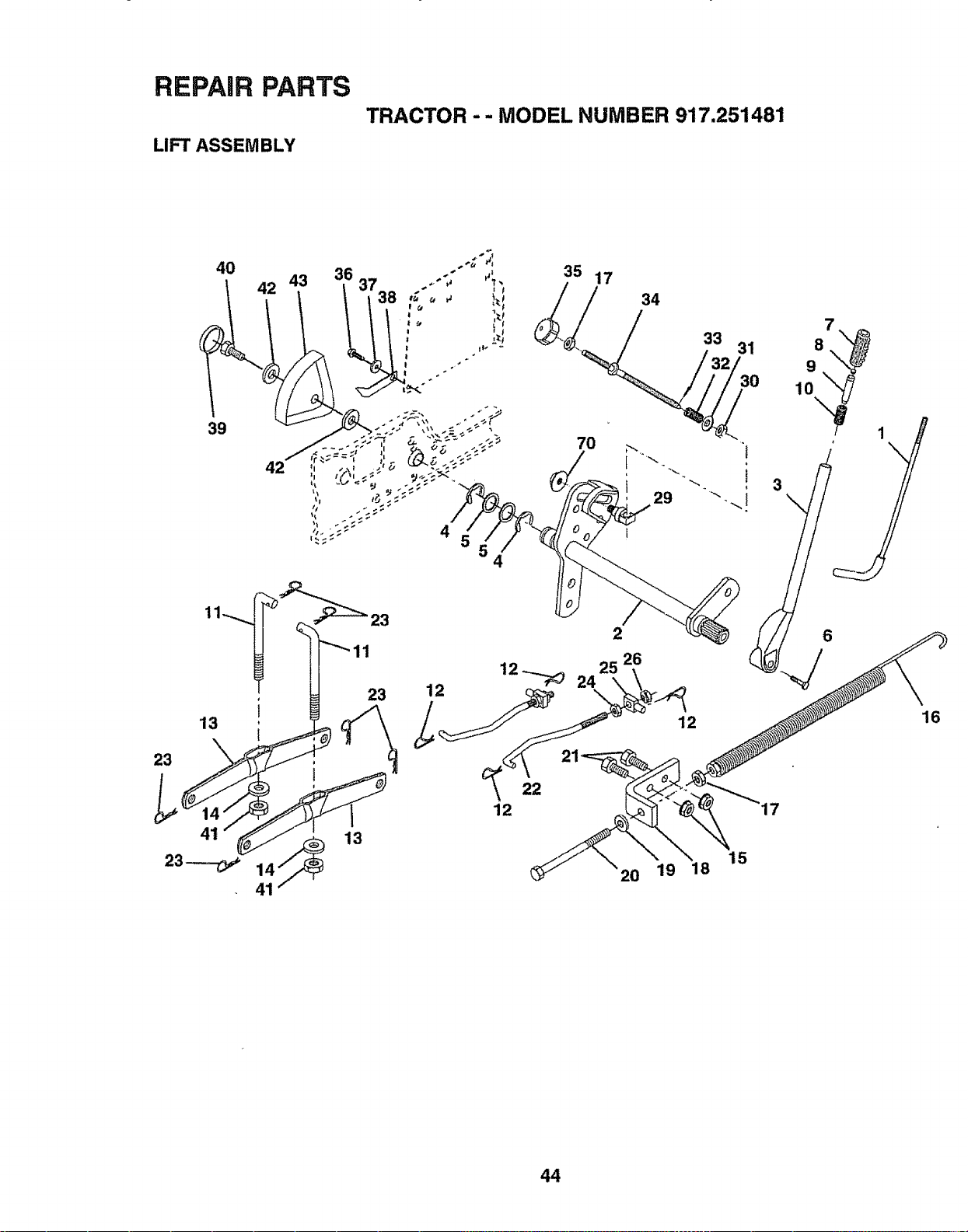
REPAIR PARTS
LIFT ASSEMBLY
TRACTOR - - MODEL NUMBER 917.251481
23
4
35
12
41 13
41
12
22
17
7O
25
24
\
34
29
2
26
2O
12 16
15
19 18
44
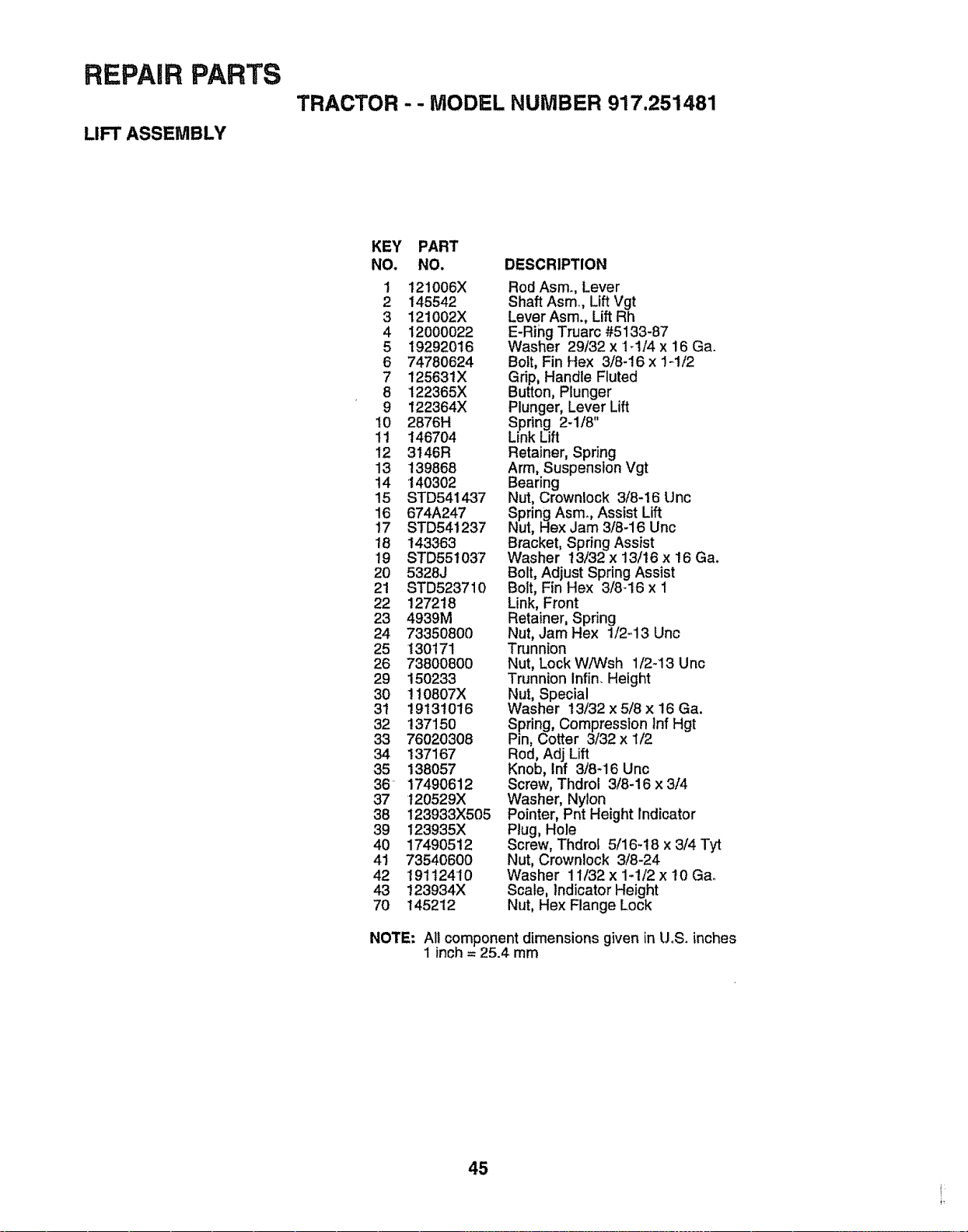
REPAIR PARTS
LIFT ASSEMBLY
TRACTOR -- MODEL NUMBER 917.251481
KEY PART
NO. NO.
1 i21006X
2 145542
3 121002X
4 12000022
5 19292016
6 74780624
7 125631X
8 122365X
9 122364×
10 2876H
11 146704
12 3146R
13 139868
14 140302
15 STD541437
16 674A247
17 STD541237
18 143363
19 STD551037
20 5328J
21 STD523710
22 127218
23 4939M
24 73350800
25 130171
26 73800800
29 150233
30 !I0807X
3t 19131016
32 137150
33 76020308
34 137167
35 138057
36 17490612
37 120529)(
38 123933X505
39 123935X
40 17490512
41 73540600
42 t91t2410
43 123934X
70 145212
DESCRIPTION
Rod Asm., Lever
Shaft Asm, Lift Vgt
Lever Asm. Lift Rh
E-Ring Truarc #5133-87
Washer 29/32 x 1-1t4 x 16 Ga.
Bolt, Fin Hex 3/8-16 x 1_1/2
Grip, Handle Fluted
Button, Plunger
Plunger, Lever Lift
Spring 2-1/8"
Link Lift
Retainer, Spring
Arm, Suspenslon Vgt
Bearing
Nut, Crownlock 3/8-16 Unc
Spring Asm. Assist Lift
Nut, Hex Jam 3/8-16 Unc
Bracket, Spring Assist
Washer 13/32 x 13/16 x 16 Ga.
Bolt, Adjust Spring Assist
Bolt, Fin Hex 3/8_16 x 1
Link, Front
Retainer, Spring
Nut, Jam Hex 1/2-'13 Unc
Trunnion
Nut, Lock WiWsh 1/2-13 Unc
Trunnion Infin. Height
Nut, Special
Washer 13/32 x 5/8 x 16 Ga.
Spring, Compression lnf Hgt
Pin, Cotter 3/32 x 1/2
Rod, Adj Lift
Knob, Inf 3/8-16 Unc
Screw, Thdrol 3/8-16 x 3/4
Washer, Nylon
Pointer, Pnt Height Indicator
Plug, Hole
Screw, Thdrol 5/16-18 x 3/4 Tyt
Nut, Crownlock 3/8-24
Washer 11/32 x 1-1/2 x 10 Ga_
Scale, indicator Height
Nut, Hex Flange Lock
NOTE: All component dimensions given in UoS.inches
1 inch = 25.4 mm
45
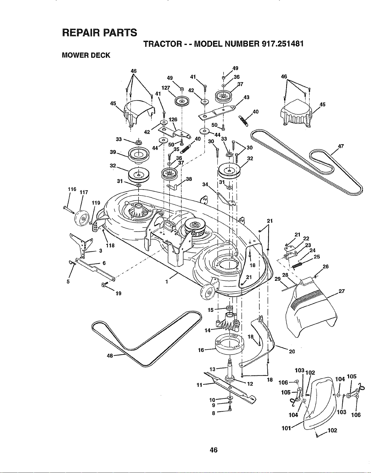
REPAIR PARTS
MOWER DECK
46
45
\
33-...._
32
117
31
TRACTOR - - MODEL NUMBER 917.251481
32
46
21
÷
26
27
9
8
12
18
46
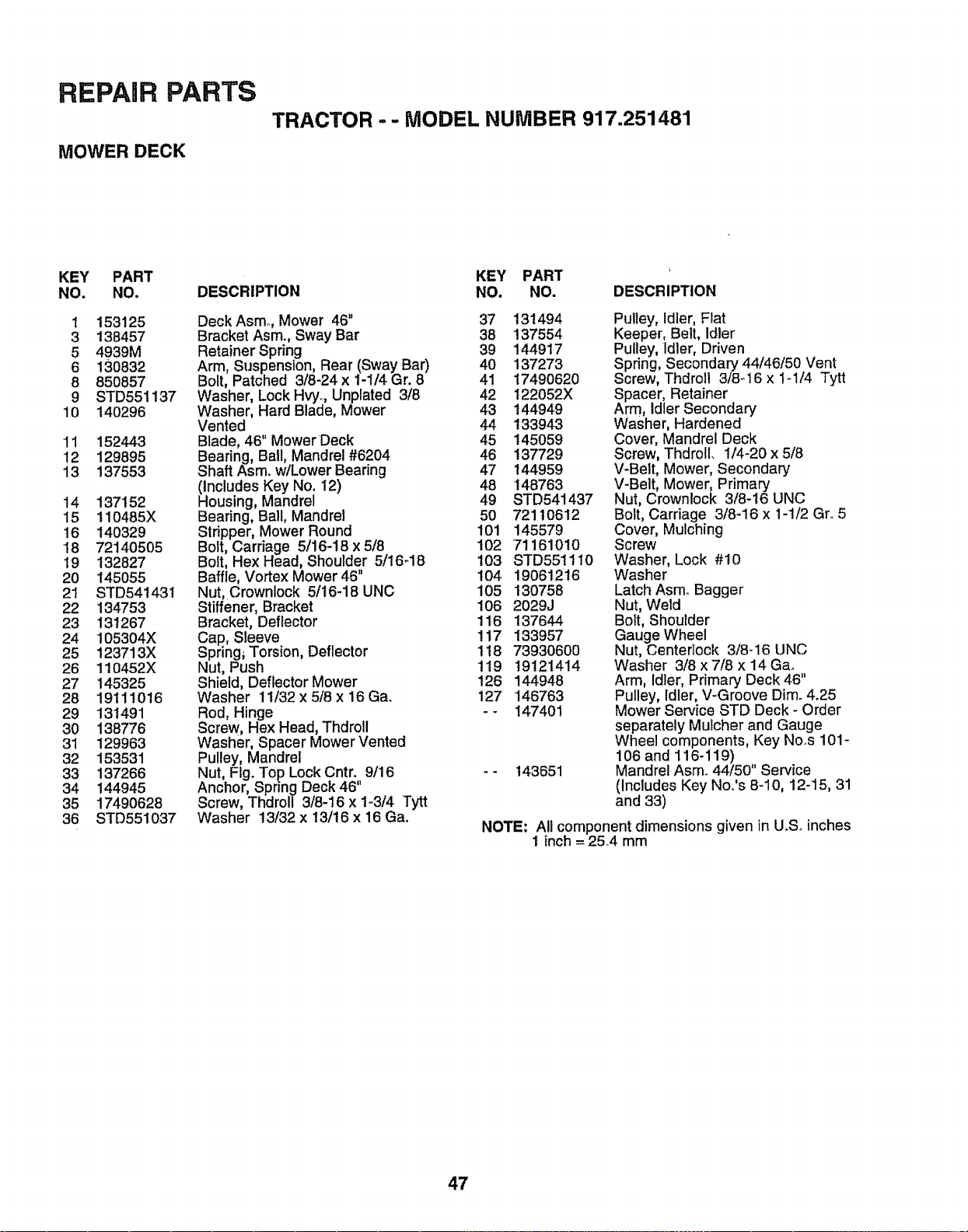
REPAnR PARTS
MOWER DECK
TRACTOR - - MODEL NUMBER 917.251481
KEY PART
NO. NO.
1 153125
3 138457
5 4939M
6 130832
8 85O857
9 STD551137
10 140296
11 152443
12 129895
13 137553
14 137152
15 110485X
16 140329
18 72140505
19 132827
20 145055
21 STD54t431
22 134753
23 131267
24 105304X
25 123713X
26 110452X
27 145325
28 19111016
29 131491
30 138776
31 129963
32 153531
33 137266
34 144945
35 17490628
36 STD551037
DESCRIPTION
Deck Asmo, Mower 46"
Bracket Asm., Sway Bar
Retainer Spring
Arm, Suspension, Rear (Sway Bar)
Bolt, Patched 3/8-24 x 1-1/4 Gr. 8
Washer, Lock Hvyo, Unplated 3/8
Washer, Hard Blade, Mower
Vented
Blade, 46" Mower Deck
Bearing, Ball, Mandrel #6204
Shaft Asm. w/Lower Bearing
(Includes Key No. 12)
Housing, Mandrel
Bearing, BalE,Mandrel
Stripper, Mower Round
Bolt, Carriage 5/16-18 x 5/8
Bolt, Hex Head, Shoulder 5/16-18
Baffle, Vortex Mower 46'*
Nut,Crownlock 5/16-18 UNC
Stiffener, Bracket
Bracket, Deflector
Cap, Sleeve
Spring_ Torsion, Deflector
Nut, Push
Shield, Deflector Mower
Washer 11/32 x 5/8 x 16 Ga_
Rod, Hinge
Screw, Hex Head, Thdroll
Washer, Spacer Mower Vented
Pulley, Mandrel
Nut, Flg. Top Lock Cntr. 9/16
Anchor, Spring Deck 46"
Screw, Thdroll 3/8-16 x 1-.3/4 Tytt
Washer 13/32 x 13/16 x 16 Ga.
KEY PART
NO. NO. DESCRIPTION
37 131494
38 137554
39 144917
40 137273
4t 1749O620
42 122052X
43 144949
44 133943
45 145059
46 137729
47 144959
48 148763
49 STD541437
5O 72110612
101 145579
102 7116101O
103 STD55!110
104 19061216
105 130758
t06 2029J
116 137644
117 133957
118 73930600
119 19121414
126 144948
127 146763
-- 147401
143651
Pulley, Idler, Flat
Keeper, Belt, Idler
Pulley, Idler, Driven
Spring, Secondary 44/46/50 Vent
Screw, Thdroll 3/8_16 x 1-1/4 Tytt
Spacer, Retainer
Arm, Idler Secondary
Washer, Hardened
Cover, Mandrel Deck
Screw, ThdrolL 1/4-20 x 5/8
V-Belt, Mower, Secondary'
V-Belt, Mower, Primary
Nut, Crownlock 3/8-16 UNC
Bolt, Carriage 3/8-16 x 1-1/2 Gr. 5
Cover, Mulching
Screw
Washer, Lock #10
Washer
Latch Asmo Bagger
Nut, Weld
Bolt, Shoulder
Gauge Wheel
Nut, Centedock 3/8_16 UNC
Washer 3/8 x 7/8 x 14 Gao
Arm, Idler, Primary Deck 46"
Pulley, Idler, V-Groove Dim_ 4.25
Mower Service STD Deck - Order
separately Mulcher and Gauge
Wheel components, Key No_s 101-
106 and 116-119) ,,
Mandrel Asm_ 44/50 Service
(Includes Key Noo's 8_10, 12-15, 31
and 33)
NOTE; All component dimensions given in U.S_ inches
1 inch = 25.4 mm
47
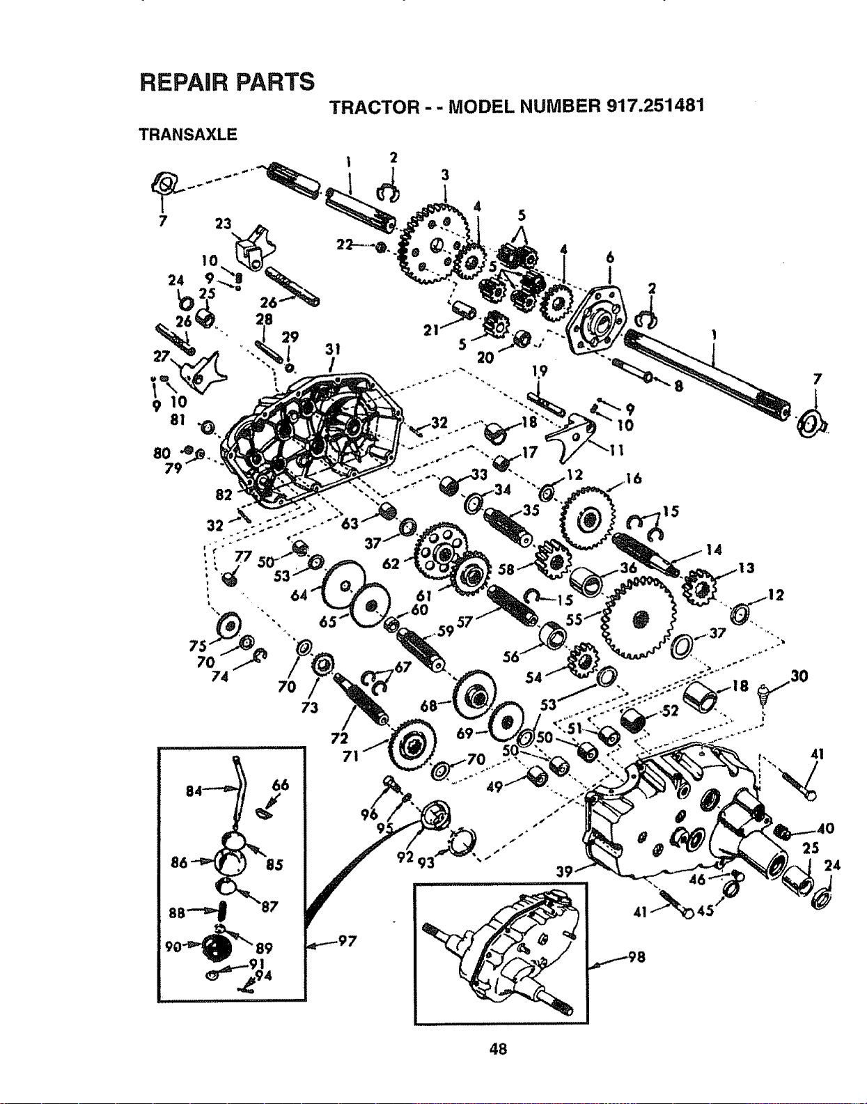
REPAIR PARTS
TRACTOR -- MODEL NUMBER 917.251481
TRANSAXLE
73
5
2O
53
I0
I
.16
@
72
7
25
24
48
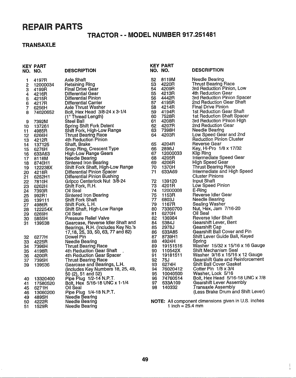
REPAIR PARTS
TRANSAXLE
TRACTOR - - MODEL NUMBER 917.251481
KEY PART
NO. NO.
1 4197R
2 12000034
3 4199R
4 4216R
5 4215R
6 4217R
7 6256H
8 74O20652
9 7392M
t0 137261
11 4985R
12 6266H
13 4212R
14 137125
15 6276H
16 633A63
17 8118M
18 8740H1
19 122238X
2O 4218R
2t 6252H1
22 781 OH
23 6262H
24 7393R
25 992R1
26 139111
27 4986R
28 122254X
29 6269H
30 5855H
31 139538
32 6277H
33 4225R
34 7396H
35 4198R
36 4200R
37 7395H
39 139536
40
41
45
46
49
5O
51
13320400
17580520
6271H
13060200
4895H
4222R
1529R
DESCRIPTION
Axle Shaft
Retaining Ring
Final Drive Gear
Differential Gear
Differential Pinion
Differential Carder
Axle Thrust Washer
Bolt, Hex Head 3/8-24 x 3-1/4
(1" Thread Length)
Steel Ba_l
Spring Shift Fork Detent
Shift Fork, High-Low Range
Thrust Bearing Race
4th Reduction Pinion
Shaft, Brake
Snap Ring, Crescent Type
High-Low Range Gears
Needle Bearing
Sintered Iron Bearing
Shift Fork Shaft, High-Low Range
Differential Pinion Spacer
Differential Pinion Bushing
Gripco Centerlock Nut 3/8-24
Shift Fork, R,.H_
Oil Seal
Sintered Iron Bearing
Shift Fork Shaft
Shift Fork, LH.
Shift Shaft, High-Low Range
Oil Seal
Pressure Relief Valve
Gearcase, Reverse Idler Shaft and
Bearings, R.H. (Includes Key No.'s
!7,18, 25, 33, 50, 63, 77 and 82)
Dowel Pin
Needle Bearing
Thrust Bearing Race
4th Reduction Gear Shaft
4th Reduction Gear Spacer
Thrust Bearing Race
Gearcase and Bearings, LH.
(Includes Key Numbers 18, 25, 49,
50 (2), 51 and 52)
Pipe Plug 1/2-14 N.PoT.
Bolt, Hex 5/16-18 UNC x !-1/4
Oil Seal
Pipe Plug 1/4-18 N.P.T.
Needle Bearing
Needle Bearing
Needle Bearing
KEY PART
NO. NO. DESCRIPTION
52 8119M
53 4220R
54 4209R
55 4213R
56 4442R
57 4195R
58 4214R
59 4194R
60 7528R
61 4208R
62 4207R
63 7398H
64 4203R
65 4204R
66 2898J
67 12000033
68 4205R
69 4206R
70 1370H
71 633A69
72 139120
73 4201R
74 12000008
75 1153R
77 6803J
79 1167R
80 7336070O
81 6270H
82 136984
84 5384J
85 2978J
86 633A85
87 8739H1
88 4924H
89 19151516
90 110542X
91 19181511
92 75J
93 6274H
94 76020412
95 10O4O5OO
96 74760514
97 633A109
98 14O332
Needle Bearing
Thrust Bearing Race
3rd Reduction Pinion, Low
4th Reduction Gear
3rd Reduction Pinion Spacer
2nd Reduction Gear Shaft
Final Drive Pinion
1st Reduction Gear Shaft
1st Reduction Shaft Spacer
3rd Reduction Plnion High
2nd Reduction Gear
Needle Bearing
Low Speed Gear and 2rid
Reduction Pinion Cluster
Reverse Gear
Key, Hi-Pro 1/8 x 17/32
Kiip Ring
Intermediate Speed Gear
High Speed Gear
Thrust Bearing Race
Intermediate and High Speed
Cluster Pinions
Input Shaft
Low Speed Pinion
E-Ring
Reverse Idler Gear
Needle Bearing
Sealing Washer
Nut, Hex, Jam 7/16-20
oil Seal
Reverse Idler Shaft
Gearshift Lever, Bent
Gearshift Cap
Gearshift Bali Cover and Pin
Shift Lever Guide Ball, Keyed
Spring
Washer 15/32 x 15/16 x t6 Gauge
Shift Mechanism Seal
Washer 9/16 x 15/16 x 12 Gauge
Gearshift Gate and Reinforcement
Shift Bali Cover Gasket
Cotter Pin 1/8 x 3/4
Washer, Lock 5/16
Bolt, Hex Head 5/16-18 UNC x 7/8
Gearshift Lever Assembly
Transaxle Assembly
(Less Brake Drum and Shift Lever)
NOTE: All component dimensions given in U.S inches
1 inch = 25_4 mm
49
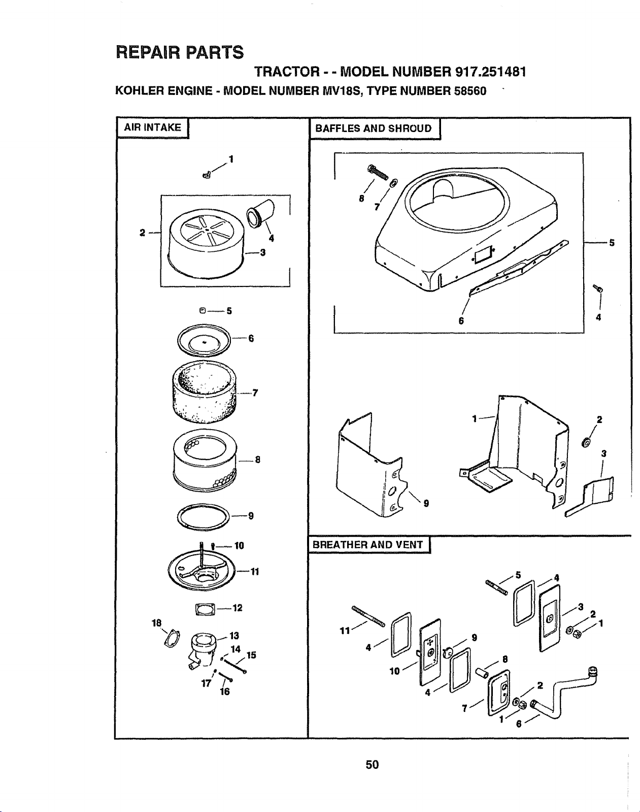
REPAIR PARTS
TRACTOR -- MODEL NUMBER 917.251481
KOHLER ENGINE - MODEL NUMBER MV18S, TYPE NUMBER 58560
1
4
[
_5
_12
18
14
(" 15
17 !
16
BAFFLES AND SHROUD,,,,,, I
/
8
7
/
_5
I
4
9
11_ _'_ _ 9 _T_71
10 "_" C:::_'_
50
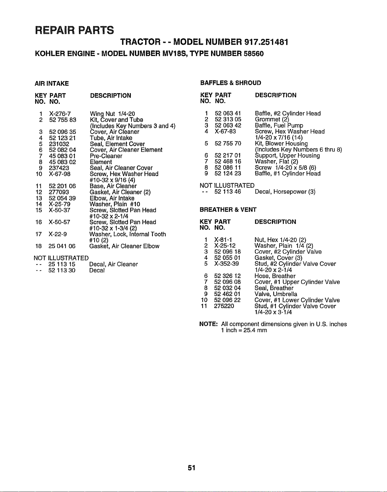
REPAIR PARTS
TRACTOR - - MODEL NUMBER 917.251481
KOHLER ENGINE- MODEL NUMBER MV18S, TYPE NUMBER 58560
AIR INTAKE
BAFFLES & SHROUD
KEY PART DESCRIPTION KEY PART
NO. NO. NO. NOo
NOT ILLUSTRATED
- - 25 113 15 Decal, Air Cleaner
-- 5211330 Decal
1 X-276-7 Wing Nut 1/4-20 I 52 063 41
2 52 755 83 Kit, Cover and Tube 2 52 313 05
(includes Key Numbers 3 and 4) 3 52 063 42
3 52 096 35 Cover, Air Cleaner 4 X-67-83
4 52 123 21 Tube, Air Intake
5 231032 Seal, Element Cover 5 52 755 70
6 52 082 04 Cover, Air Cleaner Element
7 45 083 01 Pre-Cleaner 6 52 217 01
8 45 083 02 Element 7 52 468 16
9 237423 Seal, Air Cleaner Cover 8 52 086 11
10 X-67-98 Screw, Hex Washer Head 9 52 124 23
#10-32 x 9/t6 (4)
11 52 201 06 Base, Air Cleaner
12 277093 Gasket, Air Cleaner (2)
13 52 054 39 Elbow, Air Intake
14 X-25-79 Washer, Plain #10
15 X-50_37 Screw, Slotted Pan Head BREATHER & VENT
#10_32 x 2-1/4
16 X-50-57 Screw, Slotted Pan Head KEY PART
#10-32 x 1-3/4 (2) NO. NO.
17 X-22-9 Washer, Lock, lntemat Tooth
#10 (2) 1 X-81-1
t8 25 041 06 Gasket, Air Cleaner Elbow 2 X-25-12
3 52 096 18
4 52 055 01
5 X-352-39
DESCRIPTION
Baffle, #2 Cylinder Head
Grommet (2)
Baffle, Fuel Pump
Screw, Hex Washer Head
1/4-20 x 7/16 (14)
Kit, Blower Housing
ncludes Key Numbers 6 thru 8)
upport, Upper Housing
Washer, Flat (2)
Screw 1/4-20 x 5/8 (6)
Baffle, #1 Cylinder Head
NOT ILLUSTRATED
- - 52 t13 46 Decal, Horsepower (3i
DESCRIPTION
6 52 326 '12
7 52 096 08
8 52 032 04
9 52 462 01
t0 52 096 22
11 275220
Nut, Hex 1/4:20 (2)
Washer, Plain 1/4 (2)
Cover, #2 Cylinder Valve
Gasket, Cover (3)
Stud, #2 Cylinder Valve Cover
t/4-20 x 2-1/4
Hose, Breather
Cover, #1 Upper Cylinder Valve
Seal, Breather
Valve, Umbrella
Cover, #1 Lower Cylinder Valve
Stud, #1 Cylinder Valve Cover
1/4-20 x 3_1/4
NOTE: All component dimensions given in U.S. inches
1 inch = 2&4 mm
51
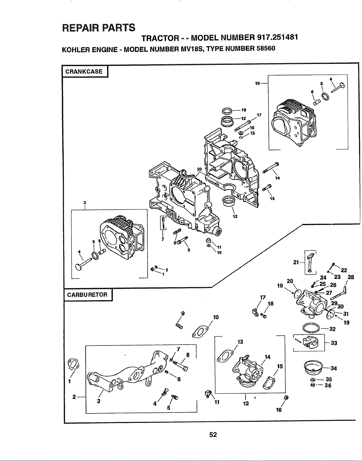
REPAIR PARTS
TRACTOR -- MODEL NUMBER 917.251481
KOHLER ENGINE - MODEL NUMBER MV18S, TYPE NUMBER 58560
CRANKCASE !
19--
17
4
3
I
CARBUREtoRI
3
9
/
%
7
5
8
24 23 28
,,2\ z_2_+26/
/ 18 _,_ _/_930
19
10
13
I ,+
+ +I +,,+ /
16
33
I
52
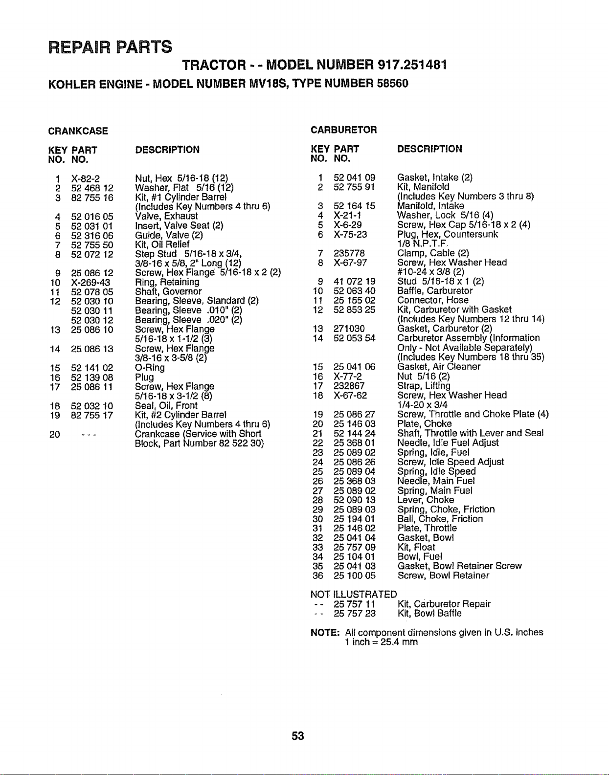
REPAIR PARTS
TRACTOR -- MODEL NUMBER 917.251481
KOHLER ENGINE - MODEL NUMBER MV18S, TYPE NUMBER 58560
CRANKCASE
CARBURETOR
KEY PART DESCRIPTION KEY PART DESCRIPTION
NO. NO. NO. NO.
9 25 086 12
10 X-269-43
11 52 078 05
12 52 030 10
52 030 11
52 03O 12
13 25 086 10
14 25 086 13
15 52 141 02
16 52139 08
17 25 086 1!
18 52 032 t0
19 82 755 17
0 _ _
1 X_82-2 Nut, Hex 5/16-18 (12) 1 52 041 09
2 52 468 !2 Washer, Flat 5/16 (12) 2 52 755 91
3 82 755 16 Kit, #1 Cylinder Barrel
(includes Key Numbers 4 thru 6) 3 52 164 15
4 52 016 05 Valve, Exhaust 4 X-21-1
5 52 031 01 Insert, Valve Seat (2) 5 X-6-29
6 52 316 06 Guide, Valve (2) 6 X-75-23
7 52 755 50 Kit, Oil Relief
8 52 072 12 Step Stud 5/16-18 x 3/4, 7 235778
3/8-16 x 5/8, 2" Long (12) 8 X-67-97
Screw, Hex Flange 5/16-18 x 2 (2)
Ring, Retaining 9
Shaft, Governor 10
Bearing, Sleeve, Standard (2) 1!
Bearing, Sleeve o010" 1221 12
Bearing, Sleeve °020"
Screw, Hex Flange 13
5/16-18 x 1-1/2 (3) t4
Screw, Hex Flange
3/8-16 x 3-5/8 (2)
O-Ring 15
Plug 16
Screw, Hex Flange 17
5/16-18 x 3-1/2 (8) 18
Seal, Oil, Front
Kit, #2 Cylinder Barrel
(Includes Key Numbers 4 thru 6)
Crankcase (Service with Short
Block, Part Number 82 522 30)
41 072 19
52 063 40
25 155 02
52 853 25
271030
52 053 54
25 041 06
X-77-2
232867
X-67-62
19 25 O8627
20 25 146 03
2t 52 14424
22 25 368 01
23 25 089 02
24 25 086 26
25 25 089 04
26 25 368 03
27 25 089 02
28 52 090 13
29 25 089 03
30 25 194 01
31 25 146 O2
32 25 041 04
33 25 757 09
34 25 104 01
35 25 041 03
36 25 100 05
Gasket, Intake (2)
Kit, Manifold
(Includes Key Numbers 3 thru 8)
Manifold, Intake
Washer, Lock 5/16 (4)
Screw, Hex Cap 5/16-18 x 2 (4)
Plug, Hex, Countersunk
1/8 N.P.T,.F.
Clamp, Cable (2)
Screw, Hex Washer Head
#10-24 x 3/8 (2)
Stud 5/16_18 x 1 (2)
Baffle, Carburetor
Connector, Hose
Kit, Carburetor with Gasket
(Includes Key Numbers 12 thru 14)
Gasket, Carburetor (2)
Carburetor Assembly (Information
Only - Not Available Separately)
(Includes Key Numbers 18 thru 35)
Gasket, Air Cleaner
Nut 5/16 (2)
Strap, Lifting
Screw, Hex Washer Head
1/4-20 x 3/4
Screw, Throttle and Choke Plate (4)
Plate, Choke
Shaft, Throttle with Lever and Seal
Needle, Idle Fuel Adjust
Spring, idle, Fuel
Screw, Idle Speed Adjust
Spring, Idle Speed
Needle, Main Fuel
Spring, Main Fuel
Lever, Choke
Spring, Choke, Friction
Ball, Choke, Friction
Plate, Throttle
Gasket, Bowl
Kit, Float
Bowl, Fuel
Gasket, Bowl Retainer Screw
Screw, Bowl Retainer
NOT ILLUSTRATED
- - 25 757 11 Kit, Carburetor Repair
- - 25 757 23 Kit, Bowl Baffle
NOTE: All component dimensions given in U,S. inches
1 inch = 25,4 mm
53
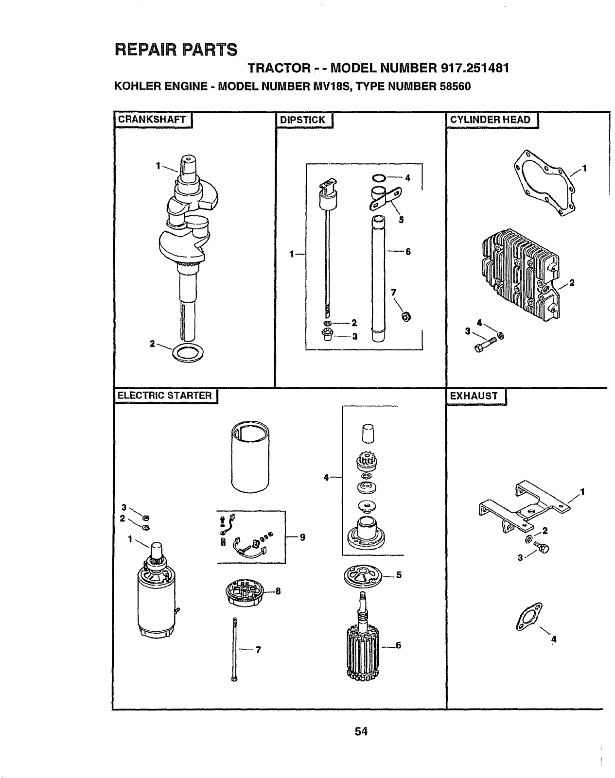
REPAIR PARTS
TRACTOR - - MODEL NUMBER 917.251481
KOHLER ENGINE - MODEL NUMBER MV18S, TYPE NUMBER 58560
CRANKSHAFT!..............
........... ii ii /i i iiiiiiii iii
ELECTRIC STARTE R !
1
z_
,,,,,,,,, ,,,,,,,,,,,, 11111 _11 i iiii i iiii1,1
DIPSTICK!
i
1
4_
@
--6
54
CYLINDER HEAD ! '"
iiiii ii iiiii iiiiiii
EXHAUST
4
i
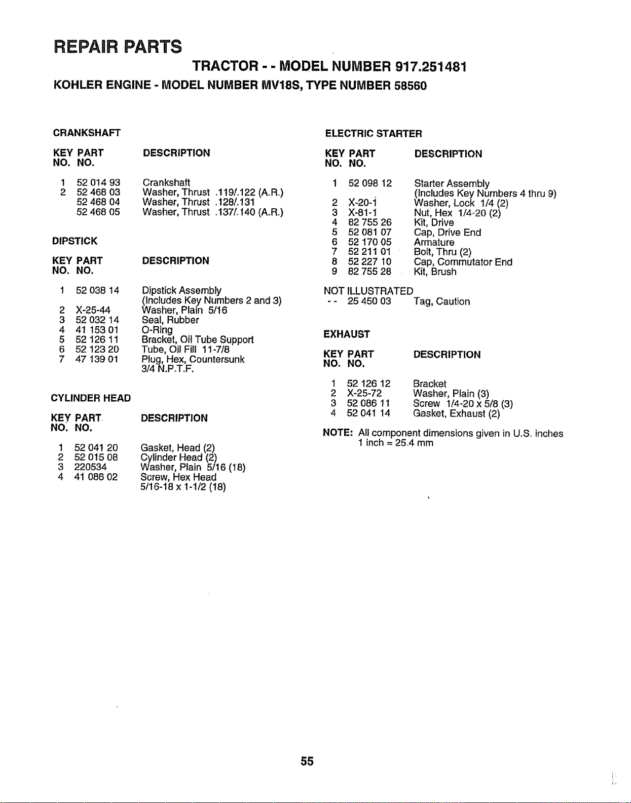
REPAIR PARTS
TRACTOR -- MODEL NUMBER 917.251481
KOHLER ENGINE - MODEL NUMBER MV18S, TYPE NUMBER 58560
CRANKSHAFT
ELECTRIC STARTER
KEY PART DESCRIPTION KEY PART
NO. NO. NO. NO.
1 52 014 93
2 52 468 03
52 468 04
52 468 05
DIPSTICK
KEY PART
NO. NO.
1 52 038 14
2 X-25-44
3 52 032 14
4 4! 153 01
5 52 126 11
6 52 123 20
7 47 I39 01
CYLINDER HEAD
KEY PART
NO_ NO.
Crankshaft
Washer, Thrust .119L122 (A,Ro)
Washer, Thrust o128/ot31
Washer, Thrust o137L140 (A.Ro)
DESCRIPTION
Dipstick Assembly
(Includes Key Numbers 2 and 3)
Washer, Plain 5/16
Seal, Rubber
O-Ring
Bracket, Oil Tube Support
Tube, Oil Fill 11-7/8
Plug, Hex, Countersunk
3/4 N.P.T.F.
DESCRIPTION
Gasket, Head (2)
Cylinder Head (2)
Washer, Plain 5/16 (18)
Screw, Hex Head
5/16-18 x 1-t/2 (18)
1 52 041 20
2 52 015 08
3 220534
4 41 086 02
DESCRIPTION
1 52 098 12
2 X-20-'l
3 X-81-t
4 82 755 26
5 52 081 07
6 52 170 05
7 52 211 01
8 52 227 10
9 82 755 28
Starter Assembly
(includes Key Numbers 4 thru 9)
Washer, Lock 1/4 (2)
Nut, Hex 1/4-20 (2)
Kit, Drive
Cap, Drive End
Armature
Bolt, Thru (2)
Cap, Commutator End
Kit, Brush
NOT ILLUSTRATED
- - 25 450 03 Tag, Caution
EXHAUST
KEY PART DESCRIPTION
NO, NO,
1 52 !26 12 Bracket
2 X-25-72 Washer, Plain (3)
3 52 086 tl Screw 1/4-20 x 5/8 (3)
4 52 041 14 Gasket, Exhaust (2)
NOTE: All component dimensions given in U°S, inches
! inch = 25.4 mm
55
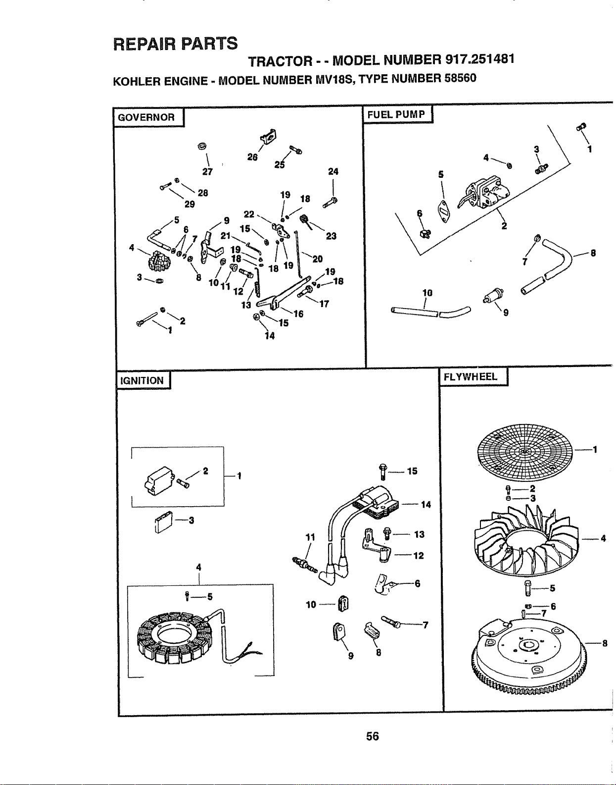
REPAIR PARTS
TRACTOR - - MODEL NUMBER 917.251481
KOHLER ENGINE - MODEL NUMBER MV18S, TYPE NUMBER 58560
13 17
14
iG"'T'O"I.........
1
4
l
11
9
10
b_15
8
3 1
56
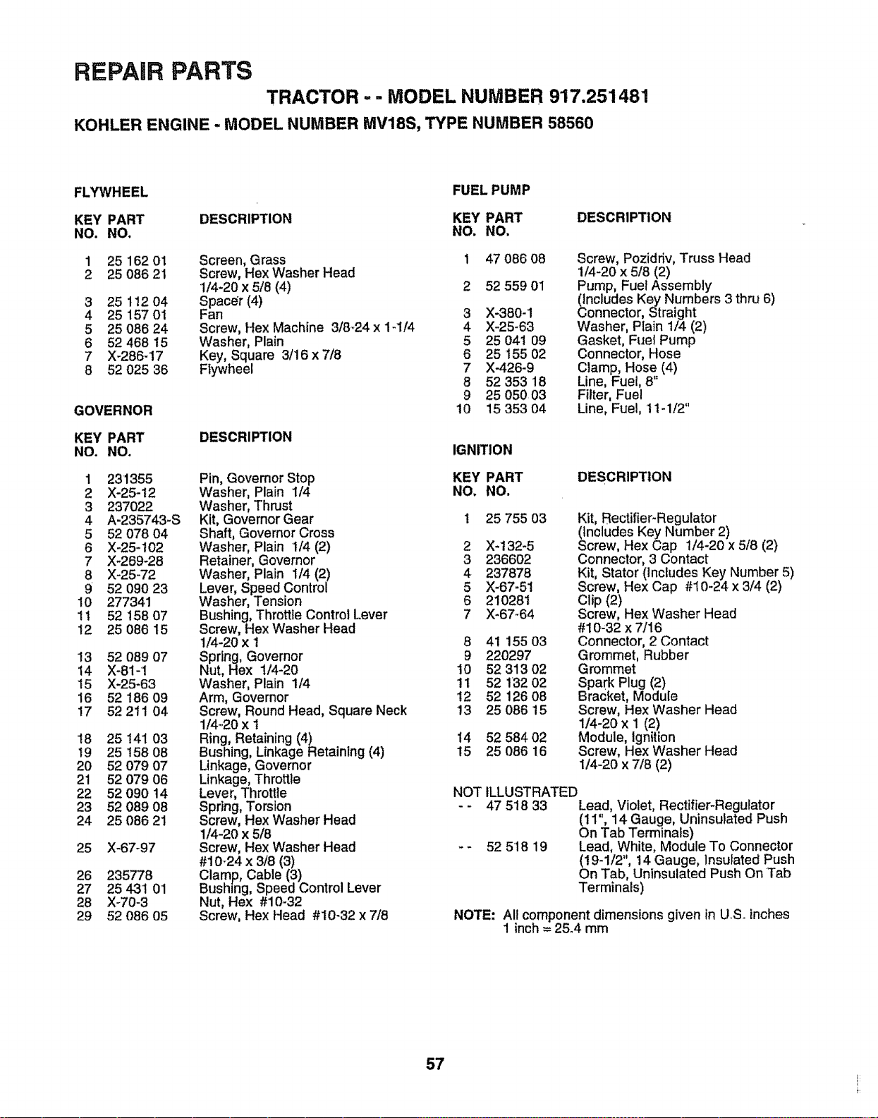
REPAIR PARTS
TRACTOR .. - MODEL NUMBER 917.251481
KOHLER ENGINE - MODEL NUMBER MV18S, TYPE NUMBER 58560
FLYWHEEL FUEL PUMP
KEY PART DESCRIPTION KEY PART DESCRIPTION
NO. NO, NO. NO.
1 25 162 01 Screen, Grass 1 47 086 08
2 25 086 21 Screw, Hex Washer Head
1/4-20 x 5/8 (4) 2 52 559 01
3 25 112 04 Spacer (4)
4 25 157 01 Fan 3 X-380-1
5 25 086 24 Screw, Hex Machine 3/8_24 x 1-1/4 4 X-25-63
6 52 468 15 Washer, Plain 5 25 041 09
7 X_286-17 Key, Square 3/16 x 7/8 6 25 155 02
8 52 025 36 Flywheel 7 X-426-9
8 52 353 18
9 2505003
GOVERNOR 10 15 353 04
KEY PART DESCRIPTION
NO. NO. IGNITION
1 231355
2 X-25-t2
3 237022
4 A-235743-S
5 52 078 04
6 X-25-102
7 X-269-28
8 X-25-72
9 52 090 23
10 277341
11 52 158 07
12 25 086 15
13 52089 07
14 X-81-1
15 X-25-63
16 52 186 09
17 52 211 04
18 25 !41 03
19 25 t58 08
20 52 07907
21 52 079 06
22 52 O9O14
23 52 089 08
24 25 086 21
25 X-67-97
26 235778
27 25431 01
28 X-70-3
29 52 086 05
Pin, Governor Stop
Washer, Plain 1/4
Washer, Thrust
Kit, Governor Gear
Shaft, Governor Cross
Washer, Plain 1/4
Retainer, Governor (2)
Washer, Plain 1/4 (2)
Lever, Speed Control
Washer, Tension
Bushing, Throttle Control Lever
Screw, Hex Washer Head
1/4-20 x 1
Spring, Governor
Nut, Hex 1t4-20
Washer, Plain I/4
Arm, Governor
Screw, Round Head, Square Neck
1/4-20 x I
Ring, Retaining (4)
Bushing, Linkage Retaining (4)
Unkage, Governor
Linkage, Throttle
Lever, Throttle
Spring, Torsion
Screw, Hex Washer Head
1/4-20 x 5/8
Screw, Hex Washer Head
#10-24 x 318 (3)
Clamp, Cable (3) .
Bushing, Speed Control Lever
Nut, Hex #10-32
Screw, Hex Head #10-32 x 7/8
Screw, Poziddv, Truss Head
1/4-20 x 5/8 (2)
Pump, Fuel Assembly
(Includes Key Numbers 3 thru 6)
Connector, Straight
Washer, Plain 1/4 (2)
Gasket, Fuel Pump
Connector, Hose
Clamp, Hose (4)
Line, Fuel, 8"
Filter, Fuel
Line, Fuel, 11-1/2"
KEY PART
NO. NO.
DESCRIPTION
25 755 03
2 X-t32-5
3 236602
4 237878
5 X-67-51
6 210281
7 X-67-64
8
9
10
!1
!2
13
14
15
41 155 O3
220297
52 313 02
52 182 02
52 126 08
25 086 15
52 584 02
25 086 16
Kit, Rectifier-Regulator
ncludes Key Number 2)
crew, Hex Cap 1/4-20 x 5/8 (2)
Connector, 3 Contact
Kit, Stator (Includes Key Number 5)
Screw, Hex Cap #I0-24 x 3/4 (2)
Clip (2)
Screw, Hex Washer Head
#10.32 x 7/16
Connector, 2 Contact
Grommet, Rubber
Grommet
Spark Plug (2)
Bracket, Module
Screw, Hex Washer Head
1/4-20 x 1 (2)
Module, Ignition
Screw, Hex Washer Head
1/4-20 x 7/8 (2)
NOT
ILLUSTRATED
47 518 33 Lead, Violet, Rectifier-Regulator
(1I", 14 Gauge, Uninsuiated Push
On Tab Terminals)
52 518 19 Lead, White, Module To Connector
(19-1/2", 14 Gauge, Insulated Push
On Tab, Uninsulated Push On Tab
Terminals)
NOTE: All component dimensions given in US.. inches
1 inch = 25°4 mm
57
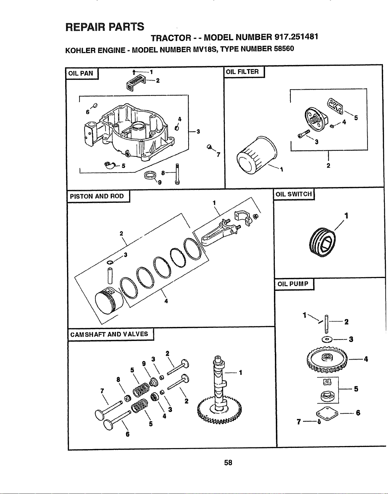
REPAIR PARTS
TRACTOR - - MODEL NUMBER 917.251481
KOHLER ENGINE - MODEL NUMBER MV18S, TYPE NUMBER 58560
PiSTO"A.ORO0I ....
7
iOiL"F,LTERI ....
CAMSHAFT AND VALVES
9
5
6
2
4
, H.
5
4
I
2
i_iL PUMP, i ....... : .............
58
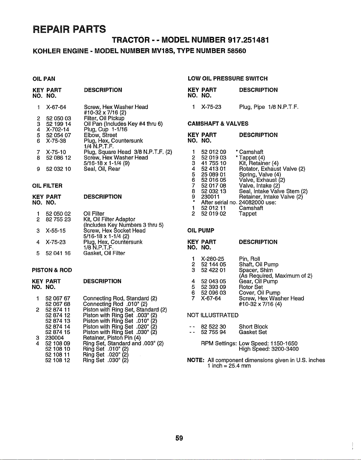
REPAIR PARTS
TRACTOR -- MODEL NUMBER 917.251481
KOHLER ENGINE - MODEL NUMBER MV18S, TYPE NUMBER 58560
OIL PAN
KEY PART DESCRIPTION
NO. NO.
1 X-67-64
2 52 050 03
3 52 199 14
4 X-702-14
5 52 054 07
6 X-75-38
7 X-75-10
8 52086 12
9 52 032 10
OIL FILTER
KEY PART
NO. NO.
1 52 050 02
2 82 755 23
3 X-55-15
4 X-75-23
5 52 041 16
PISTON & ROD
KEY PART
NO. NO.
1 52 067 67
52 067 68
2 52 874 1t
52 874 !2
52 874 13
52 874 14
52 874 15
3 23OOO4
4 52 108 09
52 108 10
52 108 11
52 108 12
Screw, Hex Washer Head
#10-32 x 7/16 (2)
Filter, Oil Pickup
Oil Pan (Includes Key #4 thru 6)
Plug, Cup 1-1/16
Elbow, Street
Plug, Hex, Countersunk
114N.P.T_F.
Plug, Square Head 318N.P.T.F. (2)
Screw, Hex Washer Head
5/16-18 x 1-1/4 (9)
Seal, Oil, Rear
DESCRIPTION
Oil Filter
Kit, Oil Fitter Adaptor
(Includes Key Numbers 3 thru 5)
Screw, Hex Socket Head
5/16-18 x 1-1/4 (2)
Plug, Hex, Countersunk
1/8 N.P.T.F.
Gasket, Oil Filter
DESCRIPTION
Connecting Rod, Standard (2)
Connecting Rod .010" (2)
Piston with Ring Set, Standard (2)
Piston with Ring Set .003 (2)
Piston with Ring Set .010" ii /
Piston with Ring Set .020"
Piston with Ring Set .030"
Retainer, Piston Pin (4)
Ring Set, Standard and °003" (2)
Ring Set .010" (2)
Ring Set .020" (2)
Ring Set .030" (2)
LOW OIL PRESSURE SWITCH
KEY PART DESCRIPTION
NO. NO.
1 X-75-23 Plug, Pipe 1/8 N.P.TFo
CAMSHAFT & VALVES
KEY PART DESCRIPTION
NO. NO,
1
2
3
4
5
6
7
8
9
1
2
52 012 09 * Camshaft
52 019 03 * Tappet (4)
41 755 10 Kit, Retainer (4)
52 413 01 Rotator, Exhaust Valve (2)
25 089 0I Spring, Valve (4)
52 016 05 Valve, Exhaust (2)
52 017 08 Valve, intake (2)
52 032 13 Seal, Intake Valve Stem (2)
230011 Retainer, Intake Valve (2)
After s_rial no_24082000 use:
52 012 11 Camshaft
52 019 02 Tappet
OIL PUMP
KEY PART DESCRIPTION
NO, NO,
1
2
3
4
5
6
7
X-280-25
52 144 05
52 422 01
52 043 05
52 393 09
52 096 03
X-67-64
Pin, Roll
Shaft, Oil Pump
Spacer, Shim
(As Required, Maximum of 2)
Gear, Oil Pump
Rotor Set
Cover, Oil Pump
Screw, Hex Washer Head
#10-32 x 7/16 (4)
NOT ILLUSTRATED
- - 82 522 30
- - 52 755 94
Short Block
Gasket Set
RPM Settings: Low Speed: 1150-1650
High Speed: 3200-3400
NOTE: All component dimensions given in U_S, inches
1 inch = 25,4 mm
59

60

SERVICE NOTES
61

SE
62
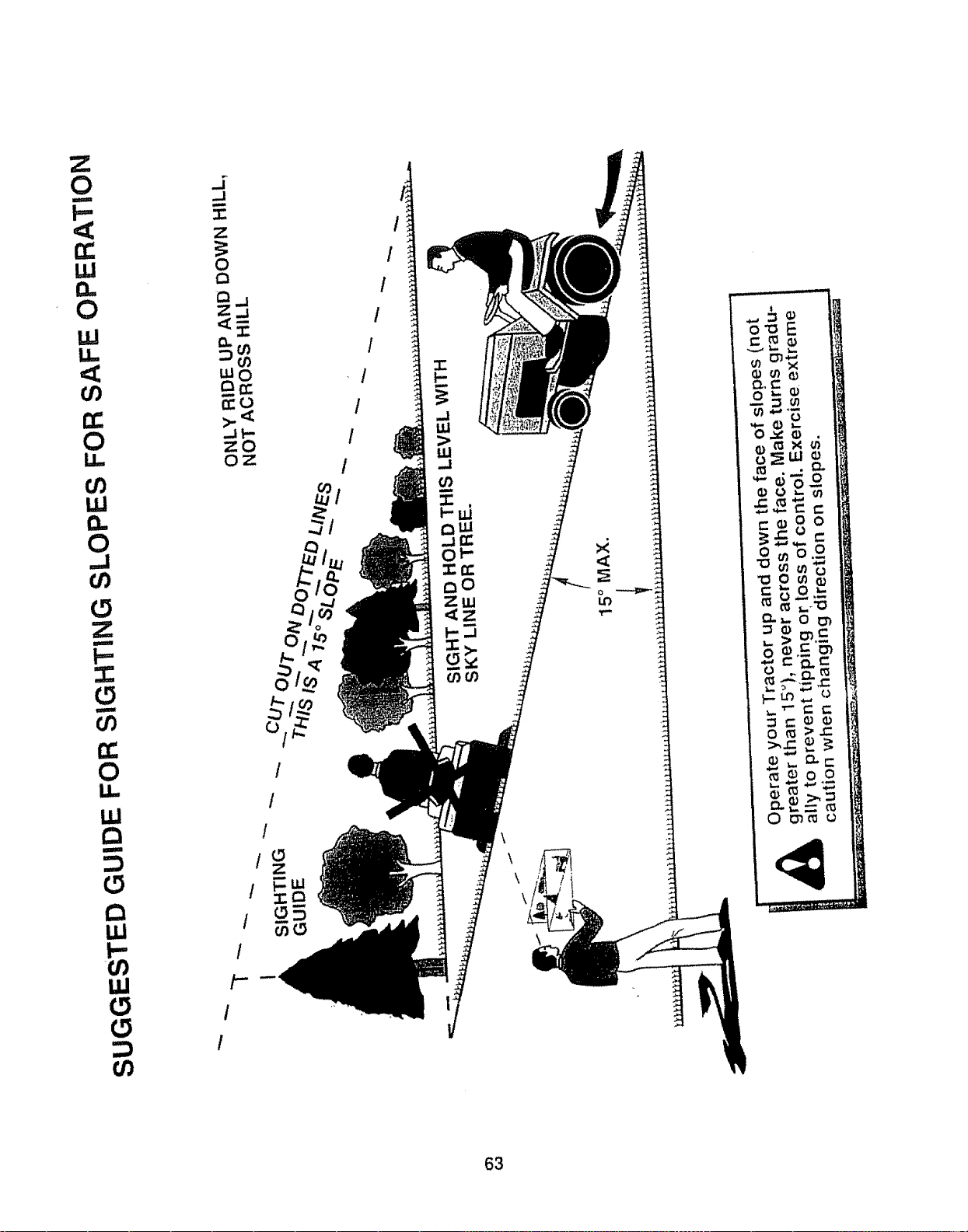
Z
0
t--
,<
0
U.I
<
CO
0
CO
UJ
0
._1
0
Z
I'-
0
0
U.,
uJ
Q
ILl
I-"
:::)
._1
J
Z
0
Qj
Z_j
mO
_0
_lt-
zO
o2:
1
/
t
I
I
I
/
/
t
/
1
/
/
/
I
1
I
Z
:I= n
o5
\
63
OWN
A
'S
UAL
MODEL NO.
917.251481
IF YOU NEED
REPAIR SERVICE
OR PARTS:
FOR REPAIR SERVICE, CALL
THIS TOLL FREE NUMBER:
1-800-4-REPAIR
(1-800-473-7247)
FOR REPLACEMENT PARTS
INFORMATION AND
ORDERING, CALL THIS
TOLL FREE NUMBER:
1-800-FON-PART
(1-800-366-7278)
FOR CONSUMER ASSISTANCE
HOT LINE, CALL THIS
TOLL FREE NUMBER:
1-800-659-5917
£RRF'IgMqN®
18.5 HP IC
ELECTRIC START
46" MOWER
6 SPEED TRANSAXLE
GARDEN TRACTOR
Each tractor has its own mcdel numoe_ " _,eng,ne nas
its own model number
The model number for your Itactor -,,,,', :,,_ :,bno :Jn :r_e
model plate located unde, ,he seal
The model number for your engine w_]l ::e found on ;he
blower housing of the engine
All parts listed herein may be ordered 'rcm any Sears
Roebuck and Co, Service CenteriDepartner:! and mosl Re-
tail Stores,
WHEN ORDERING REPAIR PARTS, ALWAYS GIVE THE
FOLLOWING INFORMATION:
• PRODUCT- TRACTOR
• MODEL NUMBER - 917,251481
• ENGINE MODEL NO . MV18S-58560
• PART NUMBER
• PART DESCRIPTION
Your Sears merchandise nas ad(Jeo ia,be #nen ,_,_
consider Sears has service units nationwde staffed ,vlh
Sears trained techn_c:aqs protess_or;a, :ecrr,car_
specifically trained Io insure lhat we meet our pledge Io
you, we service what we {eil
154330
2o15o96 JH
Ill =1 IIIIIIIMII
Printed in USA


