Loading ...
Loading ...
Loading ...
20 31-5000564 Rev. 1
ENGLISH
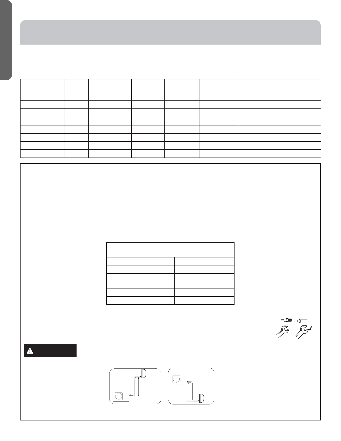
E. Install Copper Lineset
• For 2U20EH2VHA, 2U18MS2HDA1, 3U24EH2VHA, 3U24MS2HDA1, 4U36MS2HDA1, and 4U36EH2VHA1 see above
table.
• Cut the line set to length.
• Place nut over the pipe and then flare with the R-410A flaring tool.
NOTE: Follow standard practices for creating pipe flares. When cutting and reaming the tubing, use caution to prevent
dirt or debris from entering the tubing. Remember to place nut over the tubing before flaring.
• To join the line set, directly align the tubing flare to the fitting on the other pipe. Slide the nut onto the fitting and hand
tighten.
• Torque the fittings according to the specifications shown in the torque chart below.
Forced fastening without careful centering will
damage the threads and cause a refrigerant leak.
Pipe Diameter (ø) Fastening torque
Liquid side 6.35mm (1/4”) 18N.m/13.3Ft.lbs
Liquid/Gas side 9.52mm
(3/8”)
18N.m/13.3Ft.lbs
Gas side 12.7mm (1/2”) 55N.m/40.6Ft.lbs
Gas side 15.88mm( 5/8”) 60 N.m/44.3Ft.lbs
• Two wrenches are required to join the flare connection; one standard wrench and one torque wrench
adjusted to the proper settings.
• Repeat the process for attaching the other end of the line set.
CAUTION
• Max. Elevation: A Max
= 33ft / 10m (09k / 12k)
= 50ft / 15m (18k / 24k)
• Max. Length: B Max
= 50ft / 15m (09k / 12k)
= 83ft / 25m (18k / 24k)
Half union
Flare nut
Torque wrench
Spanner
Forced fastening without careful centering may
damage the threads and cause a refrigerant leak.
Pipe Diameter(ǿ) Fastening torque
Liquid side6.35mm(1/4") 18N.m/13.3Ft.lbs
Liquid/Gas side9.52mm(3/8") 42 N.m/30.1Ft.lbs
Gas side 12.7mm(1/2") 55N.m/40.6Ft.lbs
Gas side 15.88mm(5/8") 60 N.m/44.3Ft.lbs
Outdoor unit
Indoor unit
A
B
Outdoor unit
Indoor unit
A
B
A
B
Outdoor unit
Indoor unit
Oil trap
CAUTION*
Max. Elevation: A Max
= 33ft / 10m (09k / 12k)
= 50ft / 15m (18k / 24k)
In case the height of A is more than
15ft / 5m, an oil trap should be
installed every 16-23ft /5-7m
Max. Length: B Max
= 50ft / 15m (09k / 12k)
= 83ft / 25m (18k / 24k)
●
●
●
*NOTE: Oil trap is only required for
2U18MS2VH*, other multi-split systems
don’t require oil trap.
Outdoor unit
Indoor unit
A
B
Outdoor unit
Indoor unit
A
B
A
B
Outdoor unit
Indoor unit
Oil trap
CAUTION*
Max. Elevation: A Max
= 33ft / 10m (09k / 12k)
= 50ft / 15m (18k / 24k)
In case the height of A is more than
15ft / 5m, an oil trap should be
installed every 16-23ft /5-7m
Max. Length: B Max
= 50ft / 15m (09k / 12k)
= 83ft / 25m (18k / 24k)
●
●
●
*NOTE: Oil trap is only required for
2U18MS2VH*, other multi-split systems
don’t require oil trap.
INSTALLATION INSTRUCTIONS
Step 3 - Installation of the Outdoor Unit (Cont.)
Model Number Factory
Charge
Total Pipe
Length of
factory charge
Additional
charge rule
Branch
Maximum
pipe length
System
Maximum
pipe length
Minimum pipe length
Unit oz ft oz/ft ft ft ft
2U18MS2HDA1 60 50 0.2 65 98 6’ per indoor and 20’ per system
3U24MS2HDA1 67 100 0.2 82 197 6’ per indoor and 20’ per system
4U36MS2HDA1 90 131 0.2 82 230 6’ per indoor and 20’ per system
2U20EH2VHA 99 100 0.2 82 164 6’ per indoor and 20’ per system
3U24EH2VHA 99 100 0.2 82 197 6’ per indoor and 20’ per system
4U36EH2VHA1 113 131 0.2 82 230 6’ per indoor and 25’ per system
Refrigerant Charge and Pipe Length Information
Loading ...
Loading ...
Loading ...