
®
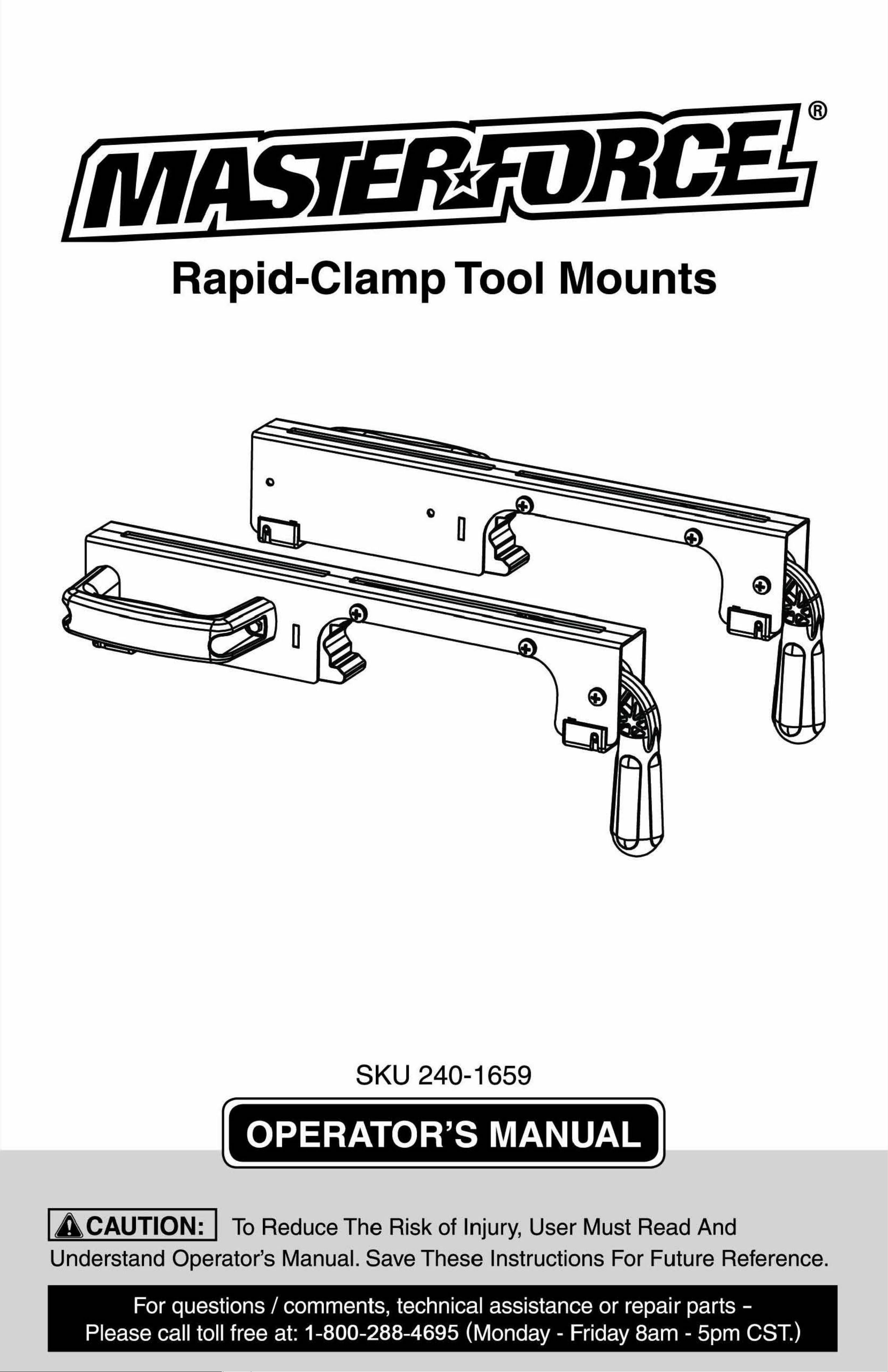
Rapid-Clamp Tool Mounts
0
a
SKU 240-1659
OPERATOR'S MANUAL
IACAUTION: ITo Reduce The Risk of Injury, User Must Read And
Understand Operator's Manual. Save These Instructions For Future Reference.
© 2012 Menards, Inc., Eau Claire, WI 54703 2/2012
For questions/ comments, technical assistance or repair parts -
Please call toll free at:
1-800-288-4695 (Monday - Friday 8am - 5pm CST.)
®
Rapid-Clamp Tool Mounts
0
a
SKU 240-1659
OPERATOR'S MANUAL
IACAUTION: ITo Reduce The Risk of Injury, User Must Read And
Understand Operator's Manual. Save These Instructions For Future Reference.
© 2012 Menards, Inc., Eau Claire, WI 54703 2/2012
For questions/ comments, technical assistance or repair parts -
Please call toll free at:
1-800-288-4695 (Monday - Friday 8am - 5pm CST.)
TABLE OF CONTENTS
Safety Symbols ..................................................................................Page 3
Safety ..................................................................................................Page 4
Parts List ............................................................................................Page 5
Overview ............................................................................................. Page 5
Assembly ............................................................................................Page 6
Maintenance.....................................................................................Page 10
Warranty ........................................................................................... Page11
SAFETY SYMBOLS
Some of the following symbols may be used on your tool. Please study them and le·arn
their meaning. Proper interpretation of these symbols will allow you to operate the tool
SAFETY SYMBOLS
c us This Symbol Designates That This Tool Is Listed By Underwriters
Laboratories, To United States And Canadian Standards
LISTED
This Symbol Designates That This Tool Is
Listed By Underwriters Laboratories
LISTED
This Symbol DesignatesThat Th1is Tool Is Listed By The lntertek
Testing Services, To United States And Canadian Standards
c~us
This Symbol Designates That This Tool Is Listed By The Canadian
~ff®
Standards Association, To United States And Canadian Standards
C
us
This Symbol Designates That This Tool ls Listed
By The Canadian Standards Association
Page 2
better and safer.
Symbol Name
V Volts
A Amperes
Hz Hertz
w Watts
~
Alternating current
-
---
Direct current
no
No-load speed
lbs Pounds
... /min Per minute
[g]
Class 11construction
e
Read the operator's
Manual
e
Wear safety glasses
(J
Wear respiratory
Protection
0
Wear hearing
Protection
8
Wear gloves
A
Warning symbol
Designation/ Explanation
Voltage
Current
Frequency (cycles per second)
Power
Type of current
Type or characteristic of current
Rotational speed, at no load
Weight
Revolutions, strokes, surface speed orbits,
etc. per minute
Double-insulated construction
To reduce the risk of injury, read
and understand operator's manual
Operation of power tool can result in
foreign objects being thrown into eyes
Use of this tool can generate dust
which may cause respiratory injury
Noise from this product
can contribute to hearing loss
Wear gloves to reduce risk of injury
Alerts user to warning messages
The purpose of safety symbols is to attract our attention to possible dangers. The safety
symbols, and the explanations with them, deserve your careful attention and understanding.
The symbol warnings do not by themselves eliminate any danger. The instructions and
warnings they give are no substitutes for proper accident prevention measures.
IA WARNING: Ie.e sure to read and understand all safety instructions in this
manual, including all safety alert symbols such as "DANGER", "WARNING" and
"CAUTION", before using this power tool. Failure to follow all instructions listed
below may result
in electric shock, fire and/or serious personal injury.
SYMBOL MEANING
A
SAFETY ALERT SYMBOL: Indicates DANGER, WARNING, OR CAUTION.
May be used in conjuntion with other symbols or pictographs
ADANGER:
Failure to obey this warning WILL result in death or serious
injury to yourself or to others. Always follow the safety precautions to reduce the
risk of fire, electric shock and personal injury.
IA WARNING: IFailure to obey this safety warning CAN result in death or
serious injury to yourself or to others. Always follow the safety precautions to
reduce the risk of fire, electric shock and personal injury.
IA CAUTION: IFailure to obey this safety warning MAY result in personal
injury to yourself or others or property damage. Always follow the safety
precautions to reduce the risk of fire, electric shock and personal injury.
Page 3
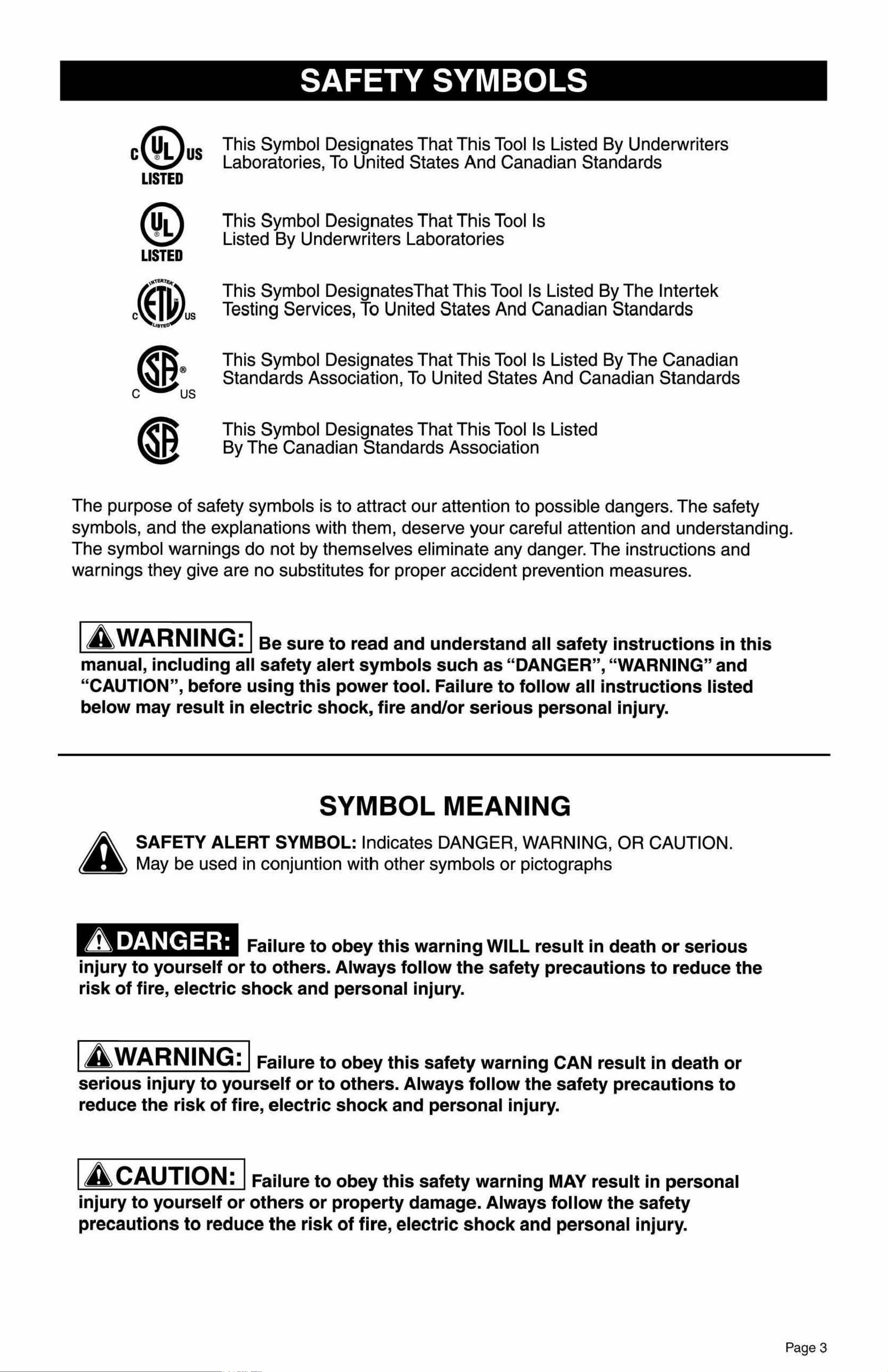
a
PARTS LIST SAFETY
GENERAL SAFETY INSTRUCTIONS FOR POWER TOOLS
Using power tools of any kind can be dangerous if safe operating procedures are not followed.
Recognizing the hazards of each tool and using them with respect and caution will considerably
limit the possibility of personal injury. However, if safety precautions are ignored, personal injury
will likely result. Always use common sense - your personal safety is your responsibility.
1. Know your power tool. Read and understand the Operator's Manual and observe the warnings
and instruction labels affixed to the tool.
2. Properly ground all tools.
3. Keep guards in place.
4. Remove adjusting keys and wrenches.
5. Keep work area clean and dry.
6. Keep children away.
7. Never leave running 1machines/tools unattended.
8. Disconn1ect tools from service.
9. Use correct tools for the job.
10. Never force a tool.
11.Wear safety apparel.
12. Wear safety glasses/goggles.
13. Never stand or sit on tools.
14. Replace damaged components immediately.
15. Make sure your work platform is sufficiently sturdy to do the specific job at hand.
16.Properly anchor blade for job being done.
17. Use correct blade for job being done.
18.Think Safety. Safety iis a combination of operator awareness, common sense and alertness at
all times.
SAFETY INSTRUCTIONS FOR MITER SAW STANDS
1. Use caution when folding or unfolding legs to limit any finger pinch points.
2. Place stand on flat and level surface to keep from rocking or tipping.
3. Make sure that work support extensions are within safe operating limits, and are properly
locked in place before using tool. Do not exceed the maximum weight of your miter saw stand.
4. Test the setup for stability before proceeding with work.
5. Be sure the miter saw is tightened securely at all mountings before use or folding the stand
for transport.
Description Part Number Qty
1 Rapid Clamp Tool Mount MF-MMA-01004A 1 set
2 Offset Mounting Bracket MF-MMP-01001 A 2 pcs
3 Nut M8 MF-MMP-01011 A 6 pcs
4 Spring Washer #8
MF-MMP-01014A 6 pcs
0
0 0
OVERVIEW
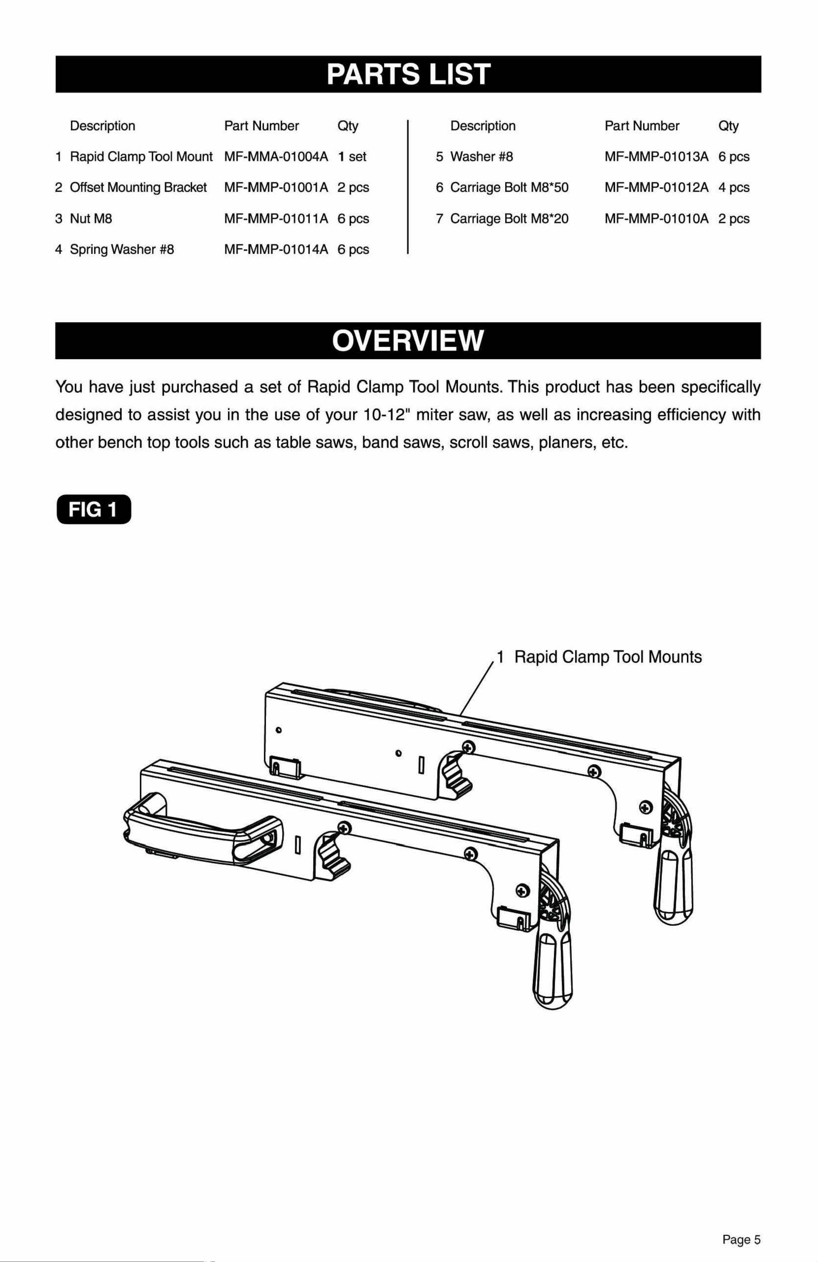
You have just purchased a set of Rapid Clamp Tool Mounts. This product has been specifically
dlesigned to assist you in the use of your
10-12" miter saw, as well as increasing efficiency with
other bench top tools such as table saws, band saws, scroll saws, planers, etc.
FIG 1
1 Rapid Clamp Tool Mounts
Description Part Number
Qty
5 Washer#8 MF-MMP-01013A 6 pcs
6 Carriage Bolt M8*50
MF-MMP-01012A 4 pcs
7 Carriage Bolt M8*20 MF-MMP-0101 0A 2 pcs
Page4 Page 5
a
PARTS LIST SAFETY
GENERAL SAFETY INSTRUCTIONS FOR POWER TOOLS
Using power tools of any kind can be dangerous if safe operating procedures are not followed.
Recognizing the hazards of each tool and using them with respect and caution will considerably
limit the possibility of personal injury. However, if safety precautions are ignored, personal injury
will likely result. Always use common sense - your personal safety is your responsibility.
1. Know your power tool. Read and understand the Operator's Manual and observe the warnings
and instruction labels affixed to the tool.
2. Properly ground all tools.
3. Keep guards in place.
4. Remove adjusting keys and wrenches.
5. Keep work area clean and dry.
6. Keep children away.
7. Never leave running 1machines/tools unattended.
8. Disconn1ect tools from service.
9. Use correct tools for the job.
10. Never force a tool.
11.Wear safety apparel.
12. Wear safety glasses/goggles.
13. Never stand or sit on tools.
14. Replace damaged components immediately.
15. Make sure your work platform is sufficiently sturdy to do the specific job at hand.
16.Properly anchor blade for job being done.
17. Use correct blade for job being done.
18.Think Safety. Safety iis a combination of operator awareness, common sense and alertness at
all times.
SAFETY INSTRUCTIONS FOR MITER SAW STANDS
1. Use caution when folding or unfolding legs to limit any finger pinch points.
2. Place stand on flat and level surface to keep from rocking or tipping.
3. Make sure that work support extensions are within safe operating limits, and are properly
locked in place before using tool. Do not exceed the maximum weight of your miter saw stand.
4. Test the setup for stability before proceeding with work.
5. Be sure the miter saw is tightened securely at all mountings before use or folding the stand
for transport.
Description Part Number Qty
1 Rapid Clamp Tool Mount MF-MMA-01004A 1 set
2 Offset Mounting Bracket MF-MMP-01001 A 2 pcs
3 Nut M8 MF-MMP-01011 A 6 pcs
4 Spring Washer #8
MF-MMP-01014A 6 pcs
0
0 0
OVERVIEW
You have just purchased a set of Rapid Clamp Tool Mounts. This product has been specifically
dlesigned to assist you in the use of your
10-12" miter saw, as well as increasing efficiency with
other bench top tools such as table saws, band saws, scroll saws, planers, etc.
FIG 1
1 Rapid Clamp Tool Mounts
Description Part Number
Qty
5 Washer#8 MF-MMP-01013A 6 pcs
6 Carriage Bolt M8*50
MF-MMP-01012A 4 pcs
7 Carriage Bolt M8*20 MF-MMP-0101 0A 2 pcs
Page4 Page 5
ASSEMBLY INSTRUCTIONS
ATTACHING YOUR MITER SAW OR OTHER BENCH TOP POWER TOOL
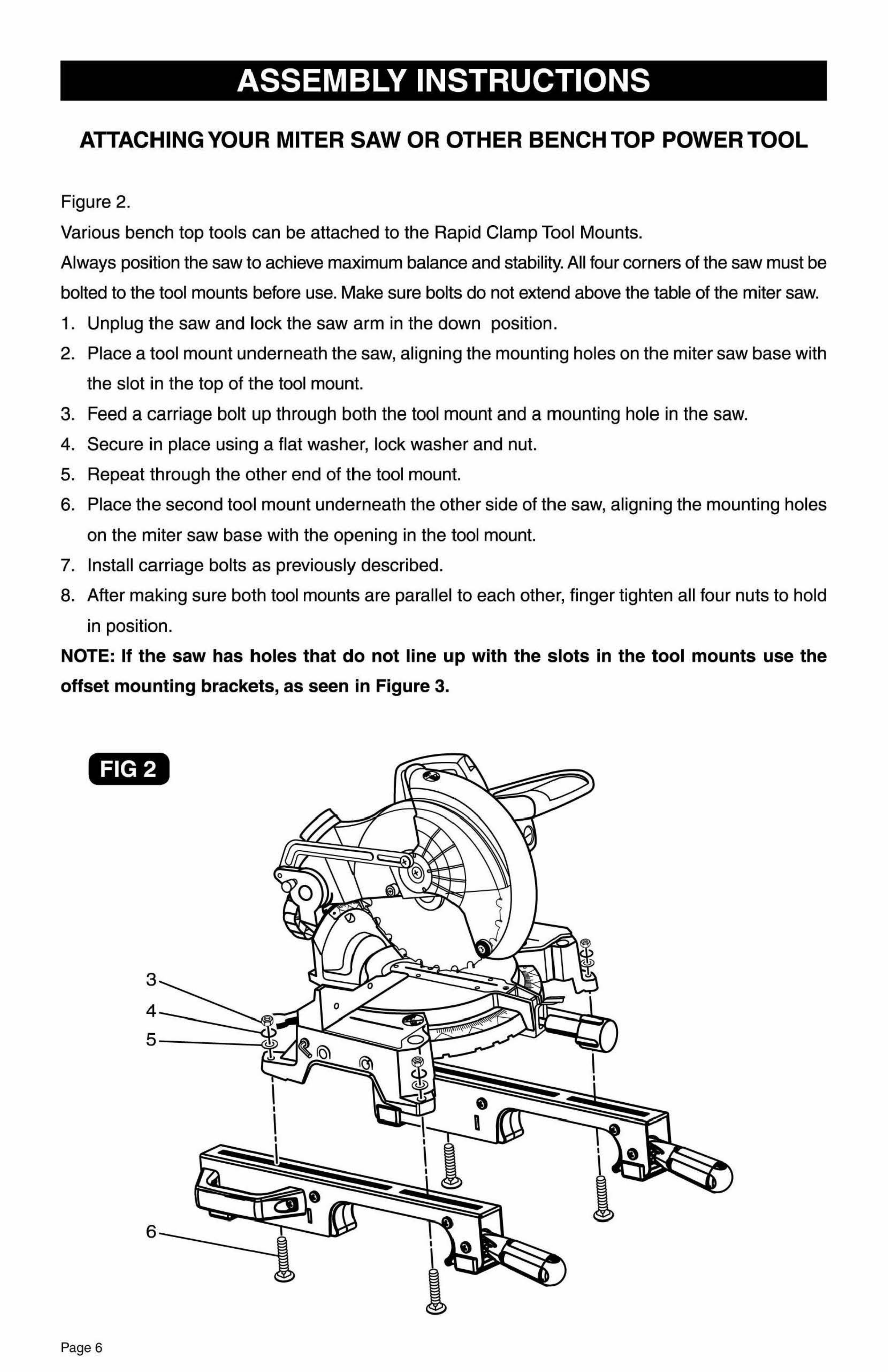
Figure 2.
Various bench top tools can be attached to the Rapid Clamp Tool Mounts.
Always position the saw to achieve maximum balance and stability. All four corners of the saw must be
bolted to the tool mounts before use. Make sure bolts do not extend above the table of the miter saw.
1. Unplug the saw and lock the saw arm in the down position.
2. Place a tool mount underneath the saw, aligning the mounting holes on the miter saw base with
the slot iin the top of the tool mount.
3. Feed a carriage bolt up through both the tool mount and a mounting hole in the saw.
4. Secure in place using a flat washer, lock washer and nut.
5. Repeat through the other end of the tool mount.
6. Place the second tool mount underneath the other side of the saw, aligning the mounting holes
on the miter saw base with the opening in the tool mount.
7. Install carriage bolts as previously described.
8. After making sure both tool mounts are parallel to each other, finger tighten all four nuts to hold
in position.
NOTE: If the saw has holes that do not line u1p with the slots in the tool mounts use the
offset mounting brackets, as seen in Figure 3.
FIG 2
3
4
5
6
I
I
I
0
I
I
n
I
I
I
a
ASSEMBLY INSTRUCTIONS
OFFSET MOUNTING
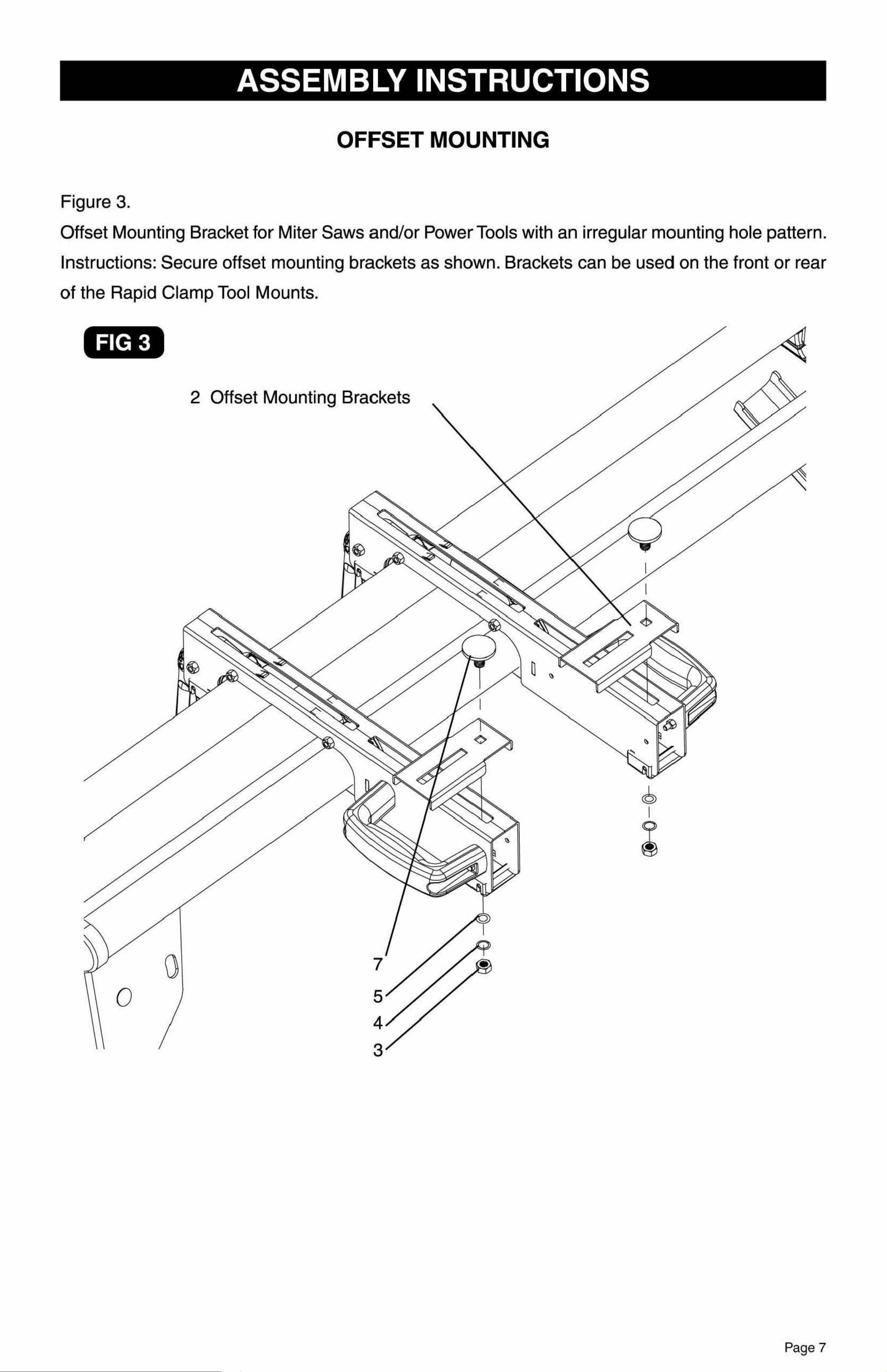
Figure 3.
Offset Mounting Bracket for Miter Saws and/or Power Tools with an irregular mounting hole pattern.
Instructions: Secure offset mounting brackets as shown. Brackets can be used on the front or rear
of the Rapid Clamp Tool Mounts.
FIG 3
2 Offset Mounting Brackets
0
Page 6
Page 7
ASSEMBLY INSTRUCTIONS
ATTACHING YOUR MITER SAW OR OTHER BENCH TOP POWER TOOL
Figure 2.
Various bench top tools can be attached to the Rapid Clamp Tool Mounts.
Always position the saw to achieve maximum balance and stability. All four corners of the saw must be
bolted to the tool mounts before use. Make sure bolts do not extend above the table of the miter saw.
1. Unplug the saw and lock the saw arm in the down position.
2. Place a tool mount underneath the saw, aligning the mounting holes on the miter saw base with
the slot iin the top of the tool mount.
3. Feed a carriage bolt up through both the tool mount and a mounting hole in the saw.
4. Secure in place using a flat washer, lock washer and nut.
5. Repeat through the other end of the tool mount.
6. Place the second tool mount underneath the other side of the saw, aligning the mounting holes
on the miter saw base with the opening in the tool mount.
7. Install carriage bolts as previously described.
8. After making sure both tool mounts are parallel to each other, finger tighten all four nuts to hold
in position.
NOTE: If the saw has holes that do not line u1p with the slots in the tool mounts use the
offset mounting brackets, as seen in Figure 3.
FIG 2
3
4
5
6
I
I
I
0
I
I
n
I
I
I
a
ASSEMBLY INSTRUCTIONS
OFFSET MOUNTING
Figure 3.
Offset Mounting Bracket for Miter Saws and/or Power Tools with an irregular mounting hole pattern.
Instructions: Secure offset mounting brackets as shown. Brackets can be used on the front or rear
of the Rapid Clamp Tool Mounts.
FIG 3
2 Offset Mounting Brackets
0
Page 6
Page 7

•
FIG 5
ASSEMBLY INSTRUCTIONS ASSEMBLY INSTRUCTIONS
MOUNTING THE TOOL ASSEMBLYTOTHE STAND TO REMOVE TOOL ASSEMBLY FROM STAND:
Figure 4.
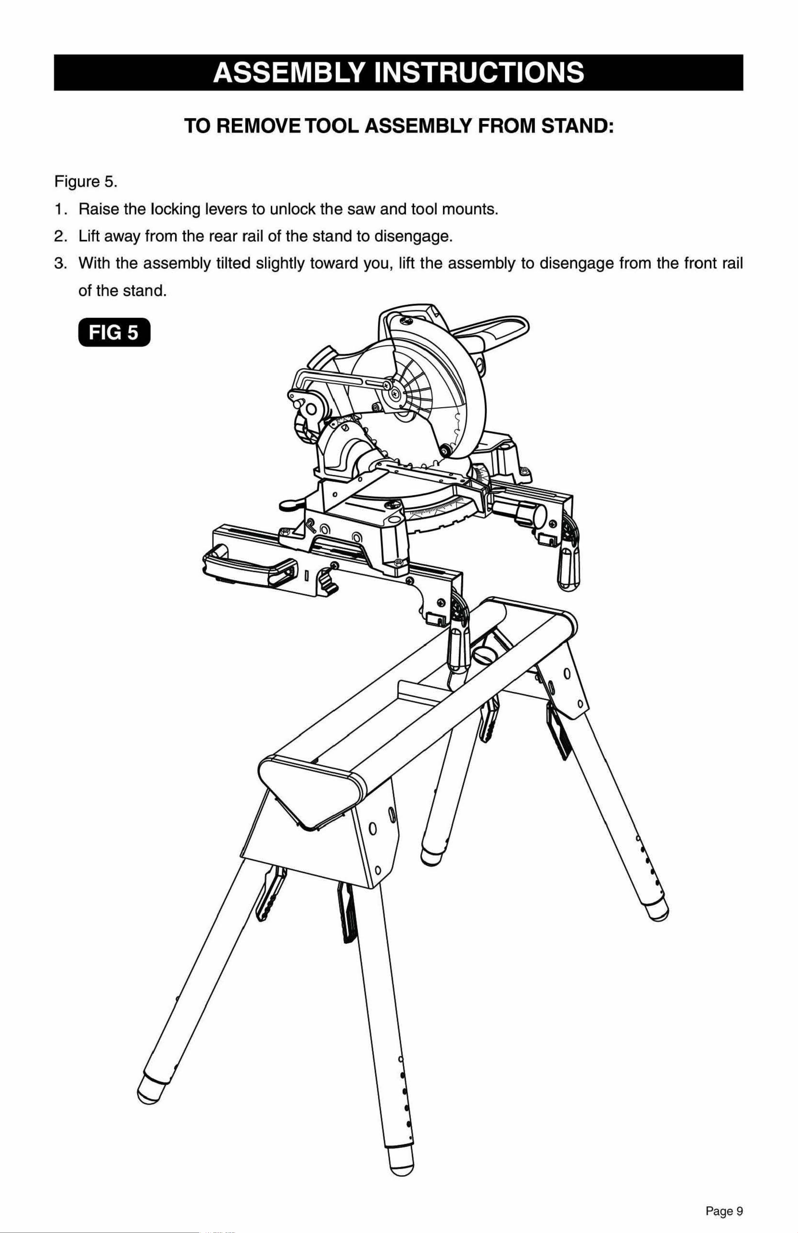
Figure 5.
Use the handles located at the rear of the tool mounts to aid in installing or removing saw and tool
1 . Raise the locking levers to unlock the saw and tool mounts.
mount assembly. 2. Lift away from the rear rail of the stand to disengage .
1. Lift the saw and tool mount assembly, allowing the assembly to tilt slightly toward your body. 3. With the assembly tilted slightly toward you, lift the assembly to disengage from the front rail
2. While still tilted toward you , hook the front edge of the tool mount assembly onto the front rail of the stand.
of the stand.
3. Lower
the tool mount assembly to allow the rear edge of the tool mount to seat fully over the rear rail.
4. Lock the tool mounts in position by lowering the locking levers .
NOTE: Continue to hold the tool mount assembly with one hand until both levers are
securely locked.
1. Check position and adjust, if necessary, to make sure the weight of the saw is evenly
balanced over the rails.
2. Ensure the saw is fully seated and locked in position, then securely tighten the four nuts holding
the saw to the tool mounts.
FIG 4
Page 8 Page 9
•
FIG 5
ASSEMBLY INSTRUCTIONS ASSEMBLY INSTRUCTIONS
MOUNTING THE TOOL ASSEMBLYTOTHE STAND TO REMOVE TOOL ASSEMBLY FROM STAND:
Figure 4.
Figure 5.
Use the handles located at the rear of the tool mounts to aid in installing or removing saw and tool
1 . Raise the locking levers to unlock the saw and tool mounts.
mount assembly. 2. Lift away from the rear rail of the stand to disengage .
1. Lift the saw and tool mount assembly, allowing the assembly to tilt slightly toward your body. 3. With the assembly tilted slightly toward you, lift the assembly to disengage from the front rail
2. While still tilted toward you , hook the front edge of the tool mount assembly onto the front rail of the stand.
of the stand.
3. Lower
the tool mount assembly to allow the rear edge of the tool mount to seat fully over the rear rail.
4. Lock the tool mounts in position by lowering the locking levers .
NOTE: Continue to hold the tool mount assembly with one hand until both levers are
securely locked.
1. Check position and adjust, if necessary, to make sure the weight of the saw is evenly
balanced over the rails.
2. Ensure the saw is fully seated and locked in position, then securely tighten the four nuts holding
the saw to the tool mounts.
FIG 4
Page 8 Page 9
MAINTENANCE
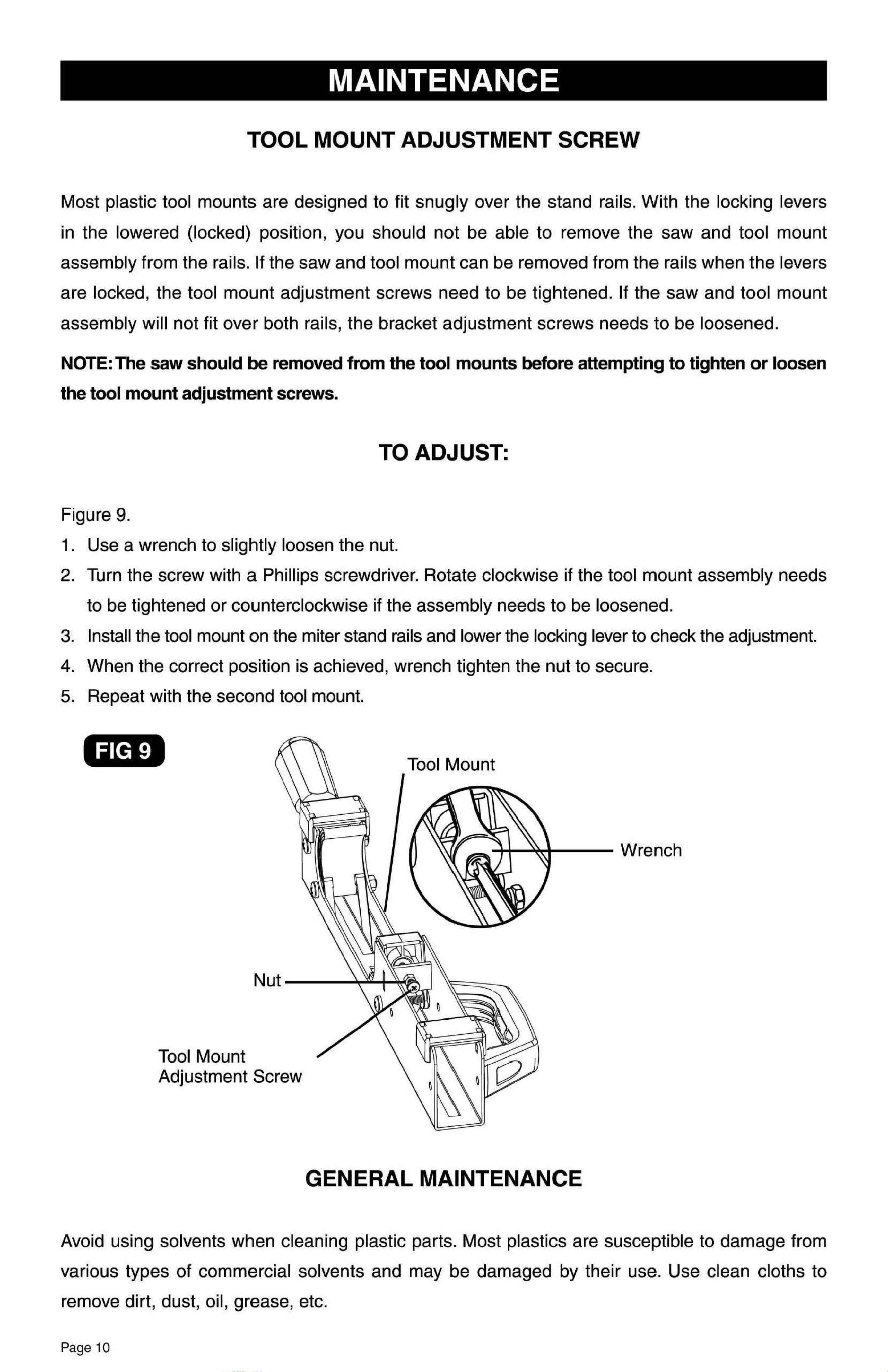
TOOL MOUNT ADJUSTMENT SCREW
Most plastic tool mounts are designed to fit snugly over the stand rails. With the locking levers
in the lowered (locked) position, you should not be able to remove the saw and tool mount
assembly from the rails. If the saw and tool mount can be removed from the rails when the levers
are locked, the tool mount adjustment screws need to be tightened. If the saw and to,ol mount
assembly will not fit over both rails, the bracket adjustment screws needs to be loosened.
NOTE:The saw should be removed from the tool mounts before attempting to tighten or loosen
the tool mount adjustment screws.
TO ADJUST:
Figure 9.
1. Use a wrench to slightly loosen the nut.
2. Turn the screw with a Phillips screwdriver. Rotate clockwise if the tool mount assembly needs
to be tightened or counterclockwise if the assembly needs to be loosened.
3. Install th,e tool mount on the miter stand rails and lower the locking lever to check the adjustment.
4. When the correct position is achieved, wrench tighten the nut to secure.
5. Repeat with the second tool mount.
FIG 9
Tool Mount
ount
ent Screw
Tool M
Adjustm
GENERAL MAINTENANCE
®
Rapid Clamp Tool Mounts
WARRANTY
90-DAY MONEY BACK GUARANTEE
This MASTERFORCE® brand power tool carries our 90-Day Money Back Guarantee.
If you are not completely satisfied with your MASTERFORCE® brand power tool for
any reason within ninety (90) days from the date of purchase, return the tool with your
original receipt to any MENARDS® retail store, and we will provide you a refund - no
questions asked.
LIMITED LIFETIME WARRANTY
MASTERFORCE® Miter Saw Stands have been manufactured to the highest
standards of quality and workmanship and are warranted to be free from defects in
materials and workmanship under normal use for the lifetime that you own the product.
If any part of the product is found to be defective during normal use, the defective
product or part will be replaced at our discretion. This warranty does not cover products
that are damaged through accident, abuse, misuse, commercial/industrial applications
or neglect. This warranty also does not cover any losses, injuries or costs including
indirect, incidental or consequential damages. This warranty may not be transferred or
sold. When requesting warranty service please call 1-800-288-4695 and have the model
number, cash register receipt and the date of purchase available when you call. If the
product is defective, we will replace the defective part at no cost to you. Some states
do not allow the exclusion or limitation of incidental damages, so the above limitations
or exclu1sions may not apply to you. This warranty gives you specific legal rights and
you may have other rights, which vary from state to state.
For questions/ comments, technical assistance or repair parts -
Please call toll free at:
1-800-288-4695(M-F 8am - 5pm Central Standard Time)
SAVE YOUR RECEIPTS
THIS WARRANTY IS VOID WITHOUT THEM
Avoid using solvents when cleaning plastic parts. Most plastics are susceptible to damage from
various types of commercial solvents and may be damaged by their use. Use clean cloths to
remove dirt, dust, oil, grease, etc.
Page 10

MAINTENANCE
TOOL MOUNT ADJUSTMENT SCREW
Most plastic tool mounts are designed to fit snugly over the stand rails. With the locking levers
in the lowered (locked) position, you should not be able to remove the saw and tool mount
assembly from the rails. If the saw and tool mount can be removed from the rails when the levers
are locked, the tool mount adjustment screws need to be tightened. If the saw and to,ol mount
assembly will not fit over both rails, the bracket adjustment screws needs to be loosened.
NOTE:The saw should be removed from the tool mounts before attempting to tighten or loosen
the tool mount adjustment screws.
TO ADJUST:
Figure 9.
1. Use a wrench to slightly loosen the nut.
2. Turn the screw with a Phillips screwdriver. Rotate clockwise if the tool mount assembly needs
to be tightened or counterclockwise if the assembly needs to be loosened.
3. Install th,e tool mount on the miter stand rails and lower the locking lever to check the adjustment.
4. When the correct position is achieved, wrench tighten the nut to secure.
5. Repeat with the second tool mount.
FIG 9
Tool Mount
ount
ent Screw
Tool M
Adjustm
GENERAL MAINTENANCE
®
Rapid Clamp Tool Mounts
WARRANTY
90-DAY MONEY BACK GUARANTEE
This MASTERFORCE® brand power tool carries our 90-Day Money Back Guarantee.
If you are not completely satisfied with your MASTERFORCE® brand power tool for
any reason within ninety (90) days from the date of purchase, return the tool with your
original receipt to any MENARDS® retail store, and we will provide you a refund - no
questions asked.
LIMITED LIFETIME WARRANTY
MASTERFORCE® Miter Saw Stands have been manufactured to the highest
standards of quality and workmanship and are warranted to be free from defects in
materials and workmanship under normal use for the lifetime that you own the product.
If any part of the product is found to be defective during normal use, the defective
product or part will be replaced at our discretion. This warranty does not cover products
that are damaged through accident, abuse, misuse, commercial/industrial applications
or neglect. This warranty also does not cover any losses, injuries or costs including
indirect, incidental or consequential damages. This warranty may not be transferred or
sold. When requesting warranty service please call 1-800-288-4695 and have the model
number, cash register receipt and the date of purchase available when you call. If the
product is defective, we will replace the defective part at no cost to you. Some states
do not allow the exclusion or limitation of incidental damages, so the above limitations
or exclu1sions may not apply to you. This warranty gives you specific legal rights and
you may have other rights, which vary from state to state.
For questions/ comments, technical assistance or repair parts -
Please call toll free at:
1-800-288-4695(M-F 8am - 5pm Central Standard Time)
SAVE YOUR RECEIPTS
THIS WARRANTY IS VOID WITHOUT THEM
Avoid using solvents when cleaning plastic parts. Most plastics are susceptible to damage from
various types of commercial solvents and may be damaged by their use. Use clean cloths to
remove dirt, dust, oil, grease, etc.
Page 10