Loading ...
Loading ...
Loading ...
N$$ALLATI
TO THE nNSTALLER: Leave This Guide With
The Range.
TO THE OWNER OF THE RANGE: Retain This
Guide For Future Reference.
TOOL UST
The following tools are needed to install your new
counter unit.
o1/8" drill bit
•Electric or hand drill
•Flat bladed screwdriver
.Pencil
.Ruler or tape measure and straightedge
.Hand or saber saw
LOCATIOH
Counter space must be provided for installation of the
counter unit. When choosing a location, consider the
following:
o The cooktop should be easy to reach and lighted with
natural light during the day_
•To eliminate the risk of burns or fire by reaching over
heated surface units, cabinet storage space located
above the surface units should be avoided. If cabinet
storage space is to be provided, the risk can be
reduced by installing a range hood that projects
horizontally a minimum of 5" beyond the bottom of
the cabinets. Cabinets installed above the counter
unit may be no deeper than t3".
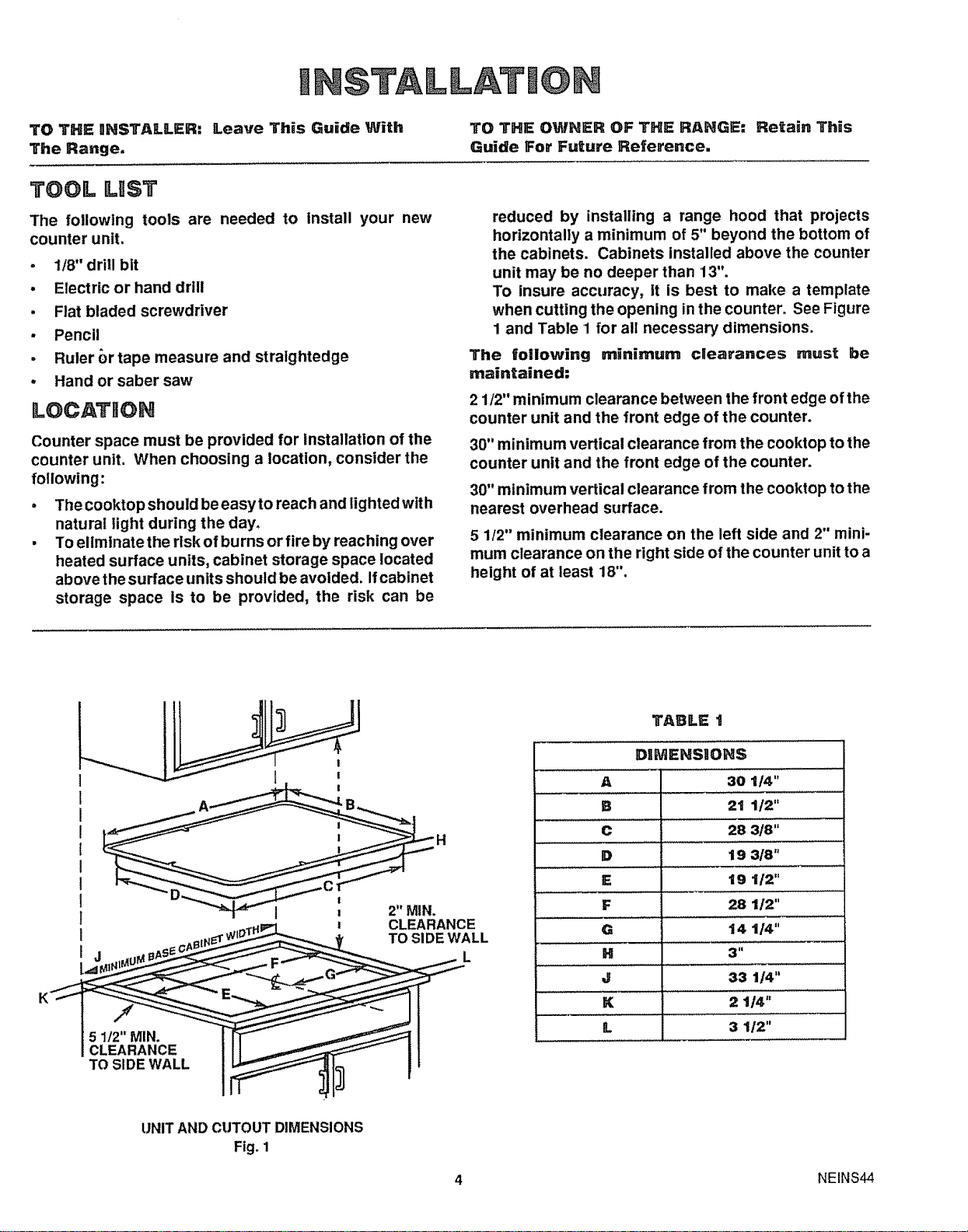
To insure accuracy, it is best to make a template
when cutting the opening in the counter. See Figure
1 and Table 1 for all necessary dimensions.
The following minimum clearances must be
maintained:
2 1/2" minimum clearance between the front edge of the
counter unit and the front edge of the counter.
30" minimum vertical clearance from the cooktop to the
counter unit and the front edge of the counter.
30" minimum vertical clearance from the cooktop to the
nearest overhead surface.
5 1/2" minimum clearance on the left side and 2" mini-
mum clearance on the right side of the counter unit to a
height of at least 18".
5 1/2" MIN.
CLEARANCE
TO SIDE WALL
CLEARANCE
TO SIDE WALL
L
TABLE t
DiMENSiONS
A30 1t4"
B 21 1/2"
......... ,,, ,,,.....................
C 28 318"
D 19 3/8"
E 19 1/2"
F 28 1/2"
G 14 1/4"
H 3"
J33 1/4"
K 2 1t4"
L 3 1/2"
UNIT AND CUTOUT DIMENSIONS
Fig. 1
4NEINS44
Loading ...
Loading ...
Loading ...