
Loading ...
Loading ...
Loading ...
10
ASSEMBLY
NOTE: If equipped with a metal chute
assembly - This assembly will install the
same the standard chute shown in the
figures of this procedure.
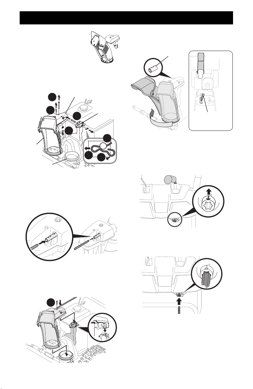
1. Remove hairpin clip (a), wing nut (or locknut if equipped)
(b) and hex screw (c) from chute control head and clevis pin
(d) and bow-tie cotter pin (e) from chute support bracket
(Figure 19).
Chute Control Head
Chute
Assembly
Chute Support
Bracket
Chute Base
d
a
c
b
e
1
2
Figure 19
NOTE: For smoothest operation, cables should all be to the left of
the chute control rod.
2. Insert chute control rod into chute control head. Push rod as
far into chute control head as possible, keeping holes in rod
pointing upward (Figure 20).
Figure 20
3. Place chute assembly onto chute base and ensure chute control
rod is positioned above lower handle. Install hex screw (c)
removed in Step 1, but do not secure with wing nut at this time
(Figure 21).
c
Figure 21
4. Squeeze trigger on 2-way/4-way chute control and rotate
chute by hand to face forward. The holes in chute control
collar will be facing up (Figure 22).
Chute Control Collar
Top View
2-Way/4-Way Chute
Control (One O’clock
Position)
Figure 22
IMPORTANT: Chute will not rotate without squeezing trigger
on 2-way/4-way chute control.
5. Rotate 2-way/4-way chute control to one o’clock position
(Figure 22) so that indicator arrow on pinion gear below
control handle faces upward (Figure 23).
Figure 23
6. Insert chute control rod into pinion gear under handle panel.
Make sure to line up hole in rod with arrow on pinion gear
(Figure 24).
Figure 24
NOTE: Chute control rod will fit snug into pinion gear.
Support rear of handle panel with one hand while inserting
rod with your other hand to ensure rod is inserted all the
way into pinion gear.
NOTE: The hole in the chute control rod is a reference for
aligning rod with indicator arrow on pinion gear, and will be
visible after rod has been fully inserted.
Loading ...
Loading ...
Loading ...