Loading ...
Loading ...
Loading ...
11
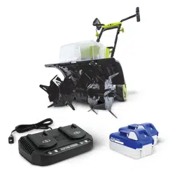
2. Connect the upper handle frame + middle handle frame
to the lower handle frame by the other 2 sets of handle
knobs + bolts, as shown (Fig. 10).
NOTE: Make sure that the handle knobs are placed inside
the handle frame. Otherwise they will aect the wheel
adjustment system.
3. Clip on the cable clips to secure the cable.
Operation
Intended Use
The 24V-X2-TLR14 cordless tiller + cultivator is designed for
small gardens and ower beds, this cordless tiller + cultivator
eectively loosens and turns over new soil. It may also be
used to mix coarse soil with fertilizer, peat, and compost. This
product may not be used to till extremely dry or wet soil.
The use of this product in rain or wet conditions is prohibited.
For safety reasons, it is essential to read the entire instruction
manual before rst use and to observe all the instructions
contained within this manual.
This product is intended for private domestic use only. It is not
intended for any commercial trade use. It must not be used for
any purposes other than those described.
Wheel Adjustment
mWARNING! Always switch the product o and remove
the batteries before making any adjustments.
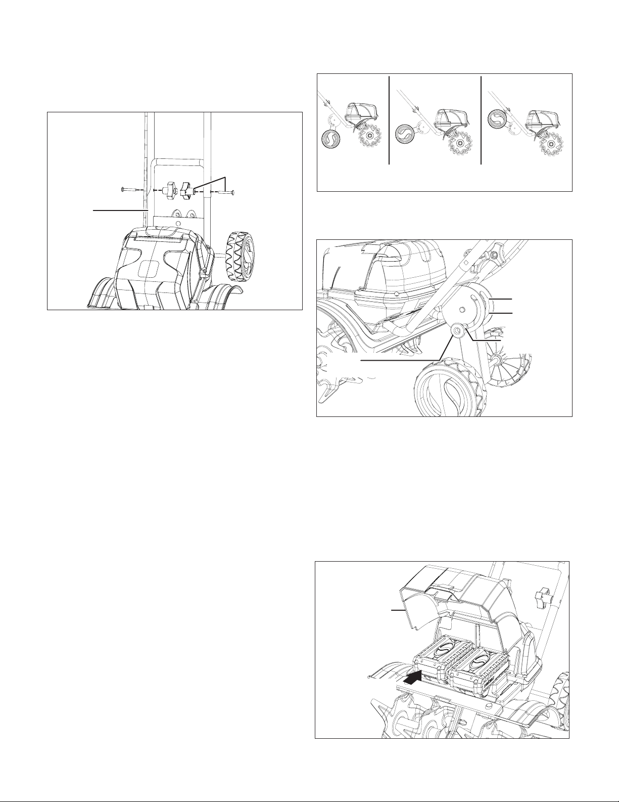
1. The wheels can be adjusted to 3 dierent positions for
better cultivating results (Fig. 11).
2. To adjust the wheel position, push the wheel adjustment
knob while moving it to the slot for desired position; let go
of the knob and make sure it locks into position (Fig. 12).
Starting the Machine
mWARNING! Rotating blades may cause serious injury.
The blades will continue to turn for a few seconds after the
tool has been switched OFF. Do not touch the rotating blades.
Contact with hot components (i.e. motor housing, gear box,
etc.) on the machine may cause burns. Allow the machine to
cool before handling.
1. Open the battery compartment cover and slide both
batteries in until they click to lock it into position, then
close the battery compartment cover (Fig. 13).
Fig. 10
Handle knob
+ bolt
Lower
handle frame
Fig. 11
Transport
position
Work
position 01
Work
position 02
Fig. 12
Wheel
adjustment knob
Work
position 02
Work
position 01
Transport
position
Fig. 13
Battery
compartment
cover
Push in
Loading ...
Loading ...
Loading ...