Loading ...
Loading ...
Loading ...
11
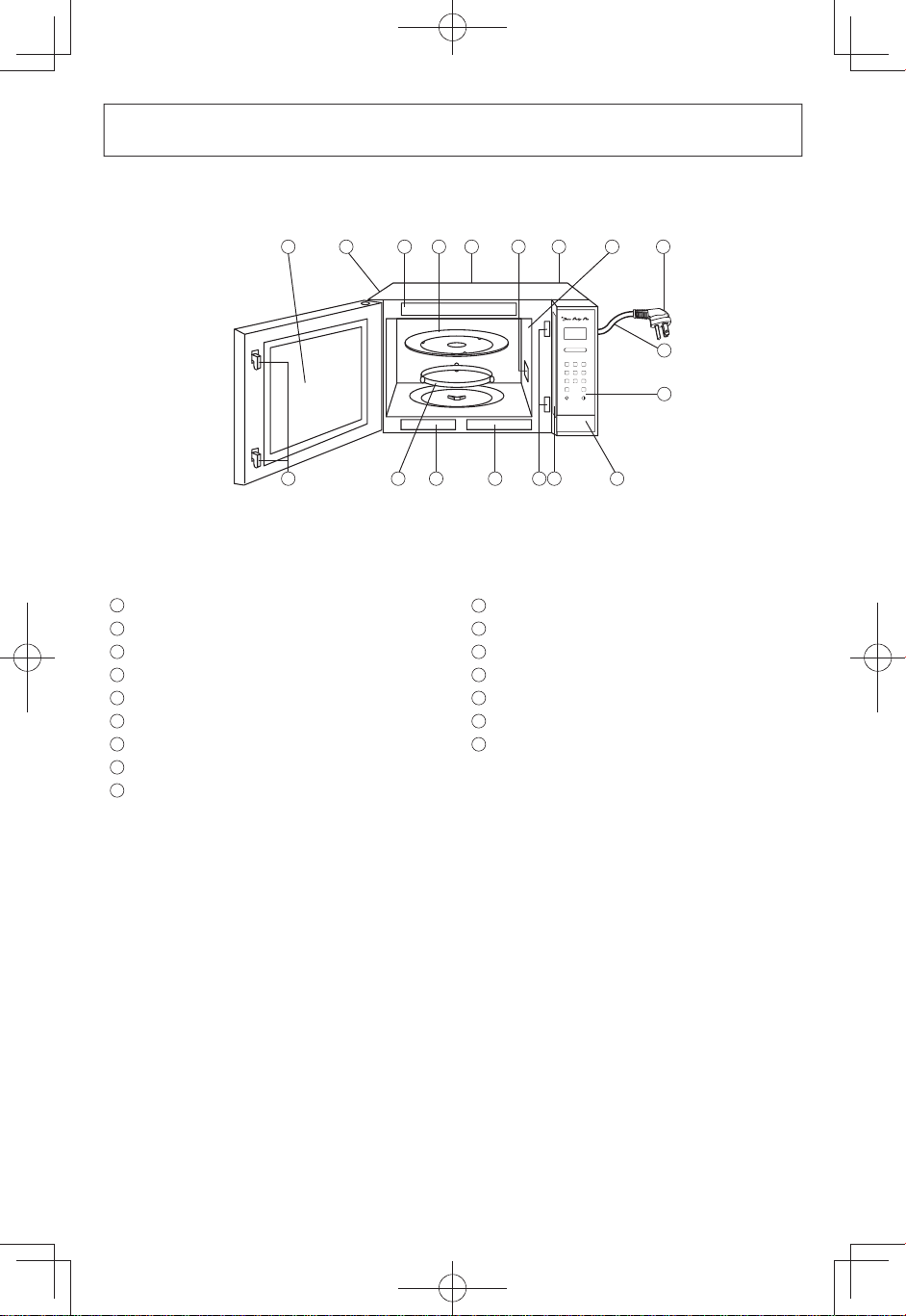
Oven Components Diagram
1
External Air Vent
2
Internal Air Vent
3
Door Safety Lock System
4
Exhaust Air Vent
5
Control Panel
6
Identification Plate
7
Glass Tray
8
Roller Ring
9
Heat/Vapor Barrier Film
(do not remove)
10
Waveguide Cover
(do not remove)
11
Door Release Button
12
Warning Label
13
Function Label
14
Picto Label
15
Power Supply Cord
16
Power Supply Plug
2
5
9
12
3
15
16
4
12
7
10
1
8
13
14
3
6
11
Note
: The illustration is for reference only.
F0003BP23CP_En.indd 11 2017/12/20 9:14:20
Loading ...
Loading ...
Loading ...