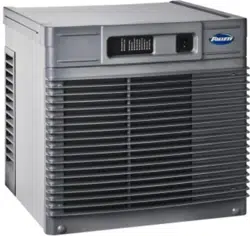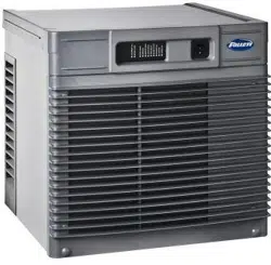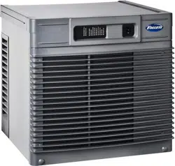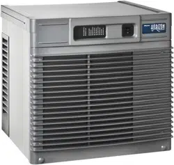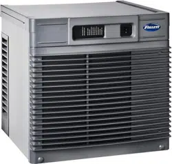
HCE710A, HME710A 1
HCE710A, HME710A
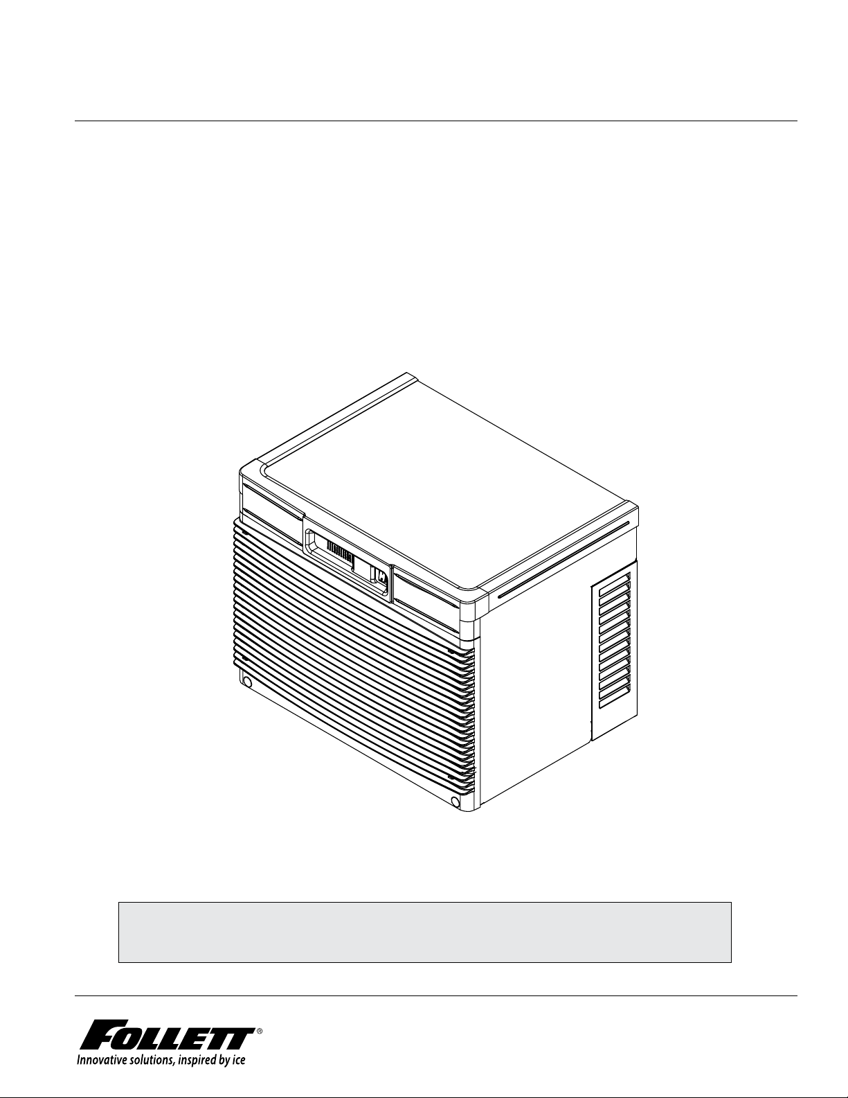
Horizon Elite™ 230 V/50 Hz Ice Machines (Self-contained)
801 Church Lane • Easton, PA 18040, USA
Toll free (877) 612-5086 • +1 (610) 252-7301
www.follettice.com
Following installation, please forward this manual
to the appropriate operations person.
Operation and Service Manual
Order parts online
www.follettice.com
01375716R02

2 HCE710A, HME710A
Contents
Welcome to Follett ............................................................................... 3
Before you begin ................................................................................ 3
Specications .................................................................................. 4
Operation ...................................................................................... 7
Preventive maintenance ....................................................................... 7
Weekly exterior care .......................................................................... 7
Monthly condenser cleaning (air-cooled icemaker only) .............................................. 7
Semi-annual evaporator cleaning (every 6 months) ................................................. 7
Service .......................................................................................11
Harvest system diagram .......................................................................11
Water system diagram ....................................................................... 13
Water level diagram ......................................................................... 13
Normal control board operation ................................................................ 14
DIP Switch Settings ......................................................................... 14
Error faults: ............................................................................... 15
Soft errors: ................................................................................ 15
Hard error: ................................................................................. 15
Run errors: ................................................................................ 15
Relay output indication: ...................................................................... 15
Evaporator ushing sequence: ................................................................. 15
Wiring diagram ............................................................................. 16
Mechanical System ............................................................................. 18
Reservoir/rear bushing disassembly ............................................................ 25
Refrigerant pressure data ..................................................................... 26
Refrigeration system diagram .................................................................. 26
Evacuation ................................................................................ 27
Ice capacity test ............................................................................ 27
Troubleshooting ................................................................................ 28
Replacement parts ............................................................................. 30
HCE710A, HME710A 3
Welcome to Follett
Follett equipment enjoys a well-deserved reputation for excellent performance, long-term reliability and outstanding
after-the-sale support. To ensure that this equipment delivers the same degree of service, we ask that you review
the installation manual (provided as a separate document) before beginning to install the unit. Our instructions are
designed to help you achieve a trouble-free installation. Should you have any questions or require technical help at
any time, please call our technical service group at (877) 612-5086 or +1 (610) 252-7301.
Before you begin
After uncrating and removing all packing material, inspect the equipment for concealed shipping damage. If
damage is found, notify the shipper immediately and contact Follett LLC so that we can help in the ling of a claim,
if necessary.
Check your paperwork to determine which model you have. Follett model numbers are designed to provide
information about the type and capacity of Follett equipment. Following is an explanation of the different model
numbers in the series.
CAUTION
§ Installation and service must be performed in accordance with all federal, state and local laws. It is the responsibility of the technician to
ensure that these requirements are met.
§ To reduce risk of shock, disconnect power before servicing.
§ A qualied person shall provide a readily accessible disconnect device incorporated into the xed wiring.
§ This appliance should be permanently connected by a qualied person in accordance with applicable codes.
§ Connect to potable water supply only.
§ Follett recommends a Follett water lter system be installed in the ice machine inlet water line (standard capacity #00130229, high capacity
#00978957, carbonless high capacity #01050442).
§ Prior to operation clean the dispenser in accordance with instructions found in this manual.
§ This appliance is designed for commercial use.
§ Warranty does not cover exterior or outside installations.
§ WARNING! To avoid a hazard due to instability of the appliance, it must be xed in accordance with the instructions.
§ Do not tilt unit further than 30° off vertical during uncrating or installation.
§ Dispenser bin area contains mechanical, moving parts. Keep hands and arms clear of this area at all times. If access to this area is
required, power to unit must be disconnected rst.
§ This appliance is not suitable for installation in an area where a water jet could be used.
§ This appliance must not be cleaned by a water jet.
§ User maintence should not be done by children.
§ Do not block air intake or exhaust.
§ If the supply cord is damaged, it must be replaced by the manufacturer, its service agent or similarly qualied persons in order to avoid a
hazard.
§ This appliance can be used by children aged 8 years and above and persons with reduced physical, sensory, or mental capabilities, or
lack of experience and knowledge if they have been given supervision or instruction concerning use of the appliance in a safe way and
understand the hazards involved. Children should be supervised to ensure that they do not play with the appliance.
§ Ice is slippery. Maintain counters and oors around dispenser in a clean and ice-free condition.
§ Ice is food. Follow recommended cleaning instructions to maintain cleanliness of delivered ice.
ConfigurationApplication
S RIDE™
(RIDE remote
ice delivery
equipment)
T Top-mount
425 up to
425 lbs
(193 kg)
710 up to
675 lbs
(306 kg)
1010 up to
1061 lbs
(482 kg)
1410 up to
1466 lbs
(665 kg)
1810 up to
1790 lbs
(812 kg)
2110 up to
2039 lbs
(925 kg)
V Vision™
H Harmony™
B Ice storage bin
J Drop-in
M Ice Manager
diverter valve
system
P Cornelius Profile
PR150
CondenserSeriesVoltageIcemaker
C 208-230/60/1 (icemaking head)
Self-contained only.
D 115/60/1 (icemaking head)
Self-contained and remote. If remote
unit, high side is 208-230/60/1.
E 230/50/1 (icemaking head)
Self-contained only.
F 115/60/1 (icemaking head)
Remote only. High side is
208-230/60/3.
MC Maestro™
Chewblet
®
(425 Series)
HC Horizon
Chewblet
(710, 1010,
1410, 1810,
2110 Series)
HM Horizon
Micro Chewblet
HC 1810D SVA
A Air-cooled, self-contained
W Water-cooled, self-contained
R Air-cooled, remote condensing unit
N Air-cooled, no condensing unit for
connection to parallel rack system
Chewblet
®
Ice Machine Model Number Configurations
4 HCE710A, HME710A
Specications
Electrical
Each ice machine requires its own separate circuit with electrical disconnect within 10 ft (3 m).
Equipment ground required.
Standard electrical:
§ 230/50/1 (6 ft (2 m) cord) requires dedicated 15A circuit
§ Amperage: 230 V @ 6A; dedicated 15A circuit required
Plumbing
WARNING
This equipment to be installed with adequate backow protection to comply with applicable federal, state,
and local codes.
§ 3/8" OD push-in water inlet (connection inside machine) - 3/8" OD tubing required
§ 3/4" MPT drain
Notes:
§ Water shut-off recommended within 10 feet (3 m).
§ Water supply must have particle ltration. Follett recommends the lter system that has integral scale inhibitors.
(Follett item# 00130286).
§ Follett does not recommend the use of water softeners or bowl scale inhibitors.
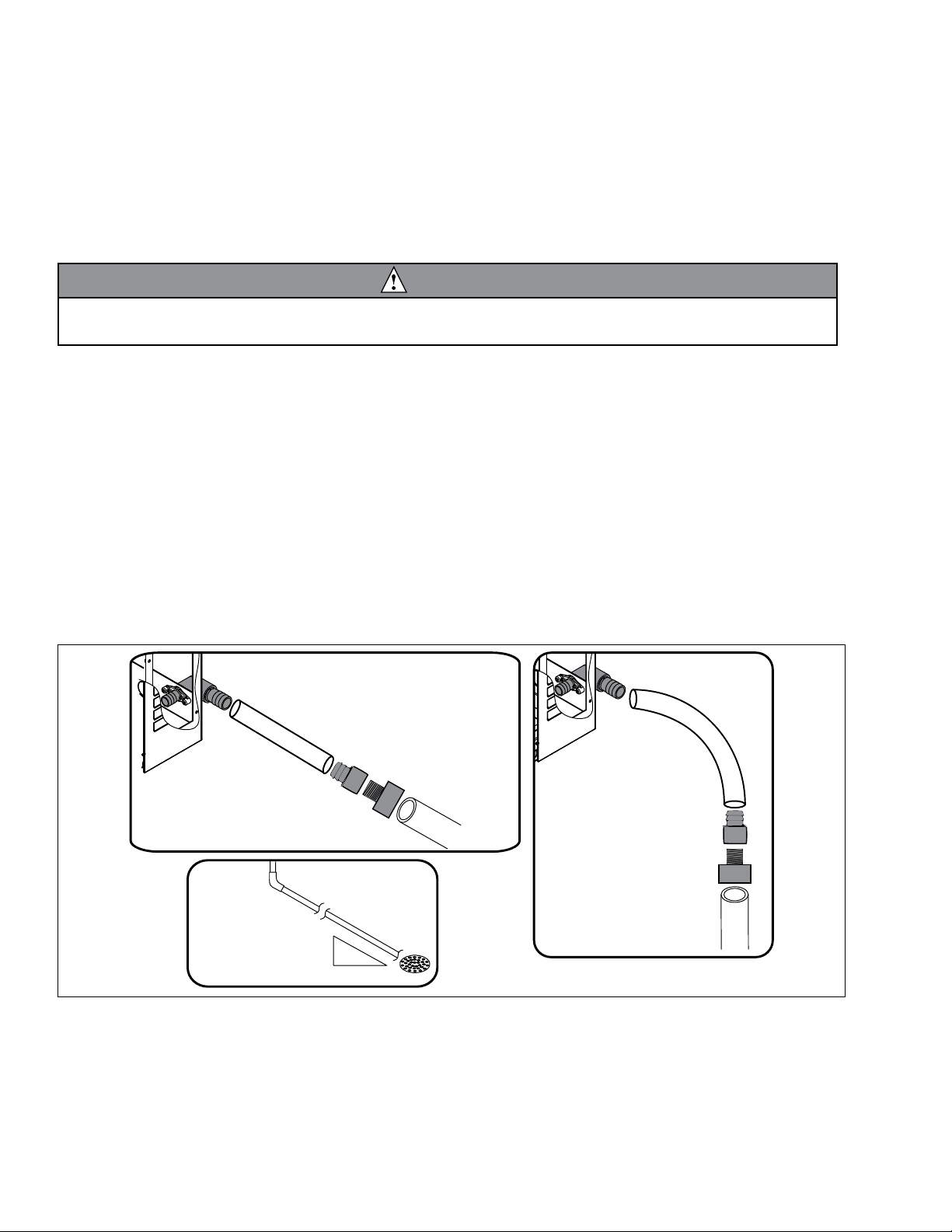
Drain plumbing
§ 3/4" MPT drain connection at the rear of the machine.
§ Drain must slope 1/4" per foot (6 mm per 30,4 cm).
§ Drain line should not be shared with any other piece of equipment.
§ Drain line cannot be reduced to a size smaller than 1 inch.
§ Drain should be piped without a vent.
3/4" barb x 3/4" FPT
1" Stand pipe/Drain
2 ft. x 1" OD
silicone tubing
Minimum 8"
radius
3/4" MPT x 1" slip
1" PVC Drain
2 ft. x 1" OD
silicone tubing
3/4" MPT x 1" slip
3/4" barb x 3/4" FPT
1'
1/4" per foot
(6,4 mm per 0,3 m)
HCE710A, HME710A 5
Ambient
Air temperature 100 F/38 C max. 50 F/10 C min.
Water temperature 90 F/32 C max. 45 F/7 C min.
Water pressure – potable 70 psi max. (483 kPa) 10 psi min. (89 kPa)
Heat rejection
710
Air-cooled 8,500 BTU/hr
Ice production
Horizon Elite 710 series, air-cooled 50 Hz
Inlet water
temperature
F (C)
Ambient air temperature F (C)
60 (16) 70 (21) 80 (27) 90 (32) 100 (38)
lb (kg) production in 24 hr
50 (10) 664 (301) 617 (280) 576 (261) 538 (244) 500 (227)
60 (16) 645 (293) 601 (272) 560 (254) 521 (236) 481 (218)
70 (21) 626 284) 582 (264) 544 (247) 506 (229) 464 (210)
80 (27) 588 (267) 544 (247) 512 (232) 481 (218) 389 (176)
90 (32) 557 (252) 519 (235) 487 (221) 455 (207) 328 (149)
Weight
Shipping 190 lb (86.2 kg)
Net 170 lb (77.2 kg)
6 HCE710A, HME710A
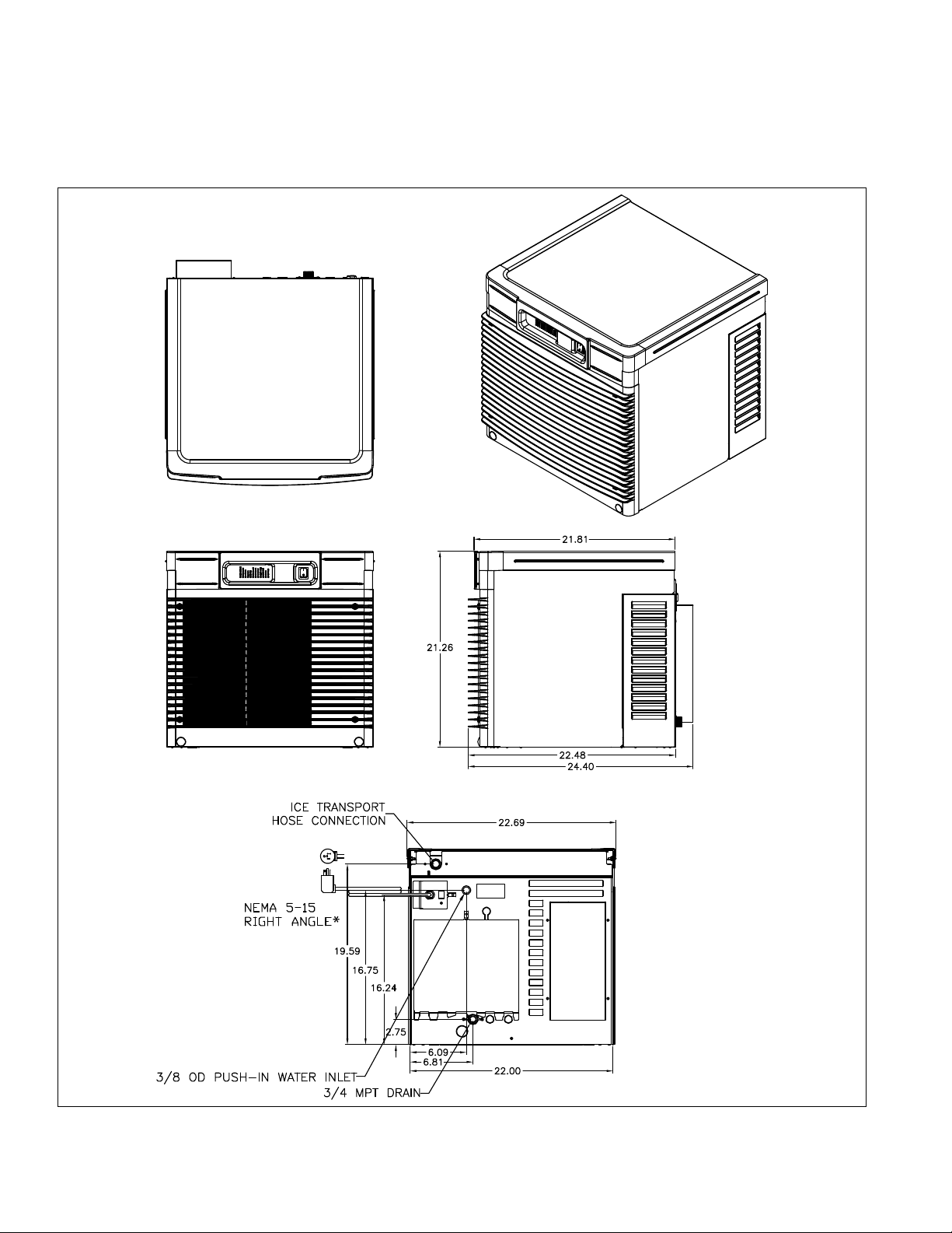
Dimensions and clearances
§ Entire front of ice machine must be clear of obstructions/connections to allow removal.
§ 1" (26 mm) clearance above ice machine for service.
§ 1" (26 mm) minimum clearance on sides.
§ The intake and exhaust air grilles must provide at least 250 sq in (1615 sq cm) of open area.
§ Air-cooled ice machines – 18" (458 mm) minimum clearance between discharge and air intake-grilles.
* Plug supplied by user on 230 V units.
HCE710A, HME710A 7
Operation
Cleaning/sanitizing and preventive maintenance (all models)
Note: Do not use bleach to sanitize or clean the icemaker.
Preventive maintenance
Periodic cleaning of Follett’s icemaker system is required to ensure peak performance and delivery of clean,
sanitary ice. The recommended cleaning procedures that follow should be performed at least as frequently as
recommended, and more often if environmental conditions dictate.
Cleaning of the condenser can usually be performed by facility personnel. Cleaning of the icemaker system,
in most cases, should be performed by your facility’s maintenance staff or a Follett authorized service agent.
Regardless of who performs the cleaning, it is the operator’s responsibility to see that this cleaning is performed
according to the schedule below. Service problems resulting from lack of preventive maintenance will not be
covered under the Follett warranty.
Weekly exterior care
The exterior may be cleaned with a stainless cleaner such as 3M Stainless Steel Cleaner & Polish or equivalent.
Monthly condenser cleaning (air-cooled icemaker only)
1. Use a vacuum cleaner or stiff brush to carefully clean condenser coils of air-cooled icemakers to ensure
optimal performance.
2. When reinstalling counter panels in front of remote icemakers, be sure that ventilation louvers line up with
condenser air duct.
Semi-annual evaporator cleaning (every 6 months)
WARNING
• Wear rubber gloves and safety goggles (and/or face shield) when handling ice machine cleaner or sanitizer.
CAUTION
• Use only Follett approved SafeCLEAN Plus™ cleaning solution.
• DO NOT USE BLEACH.
• It is a violation of Federal law to use these solutions in a manner inconsistent with their labeling.
• Read and understand all labels printed on packaging before use.
Note: Complete procedure for cleaning and sanitizing MUST be followed. Ice must be collected for
10minutes before putting ice machine back into service.
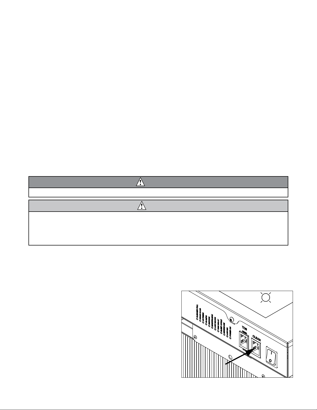
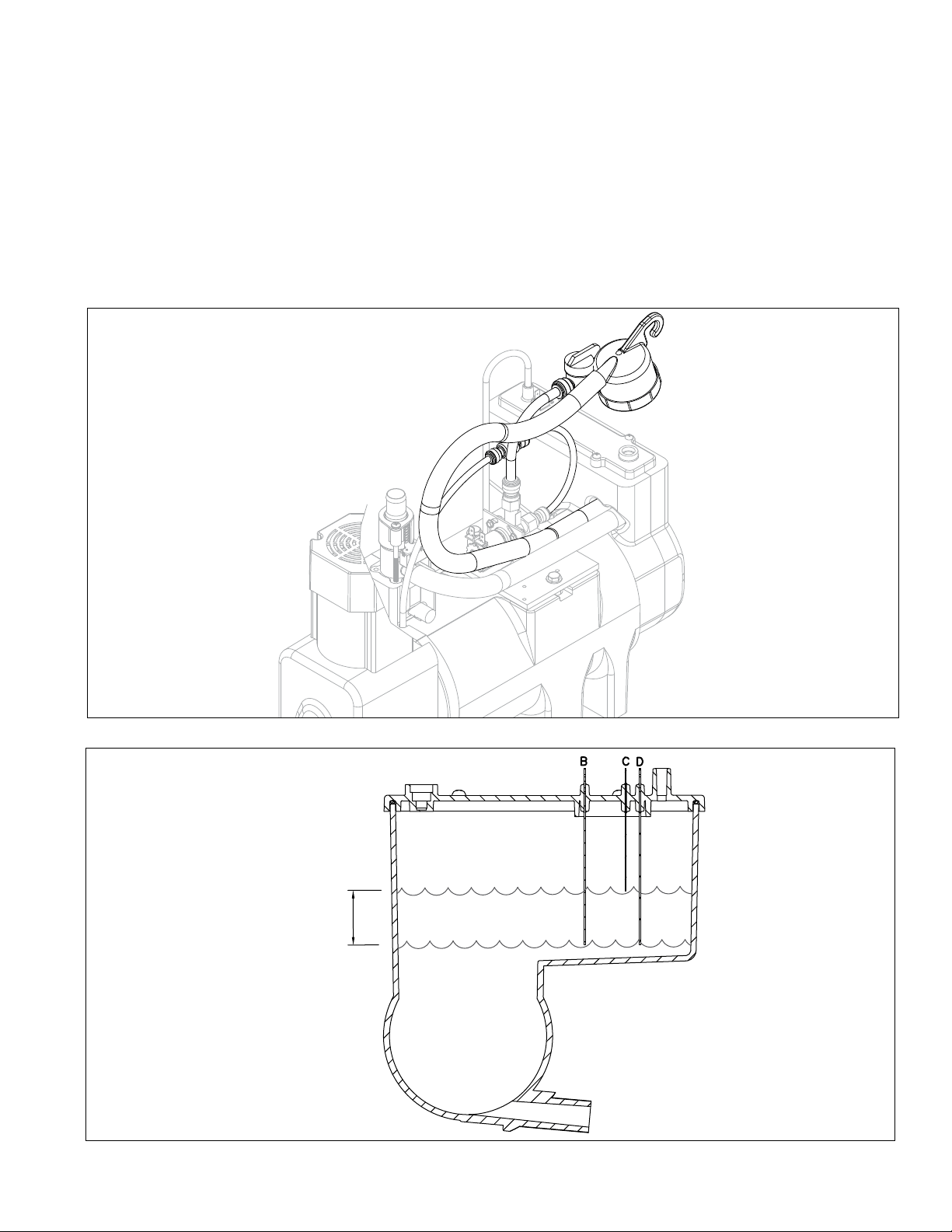
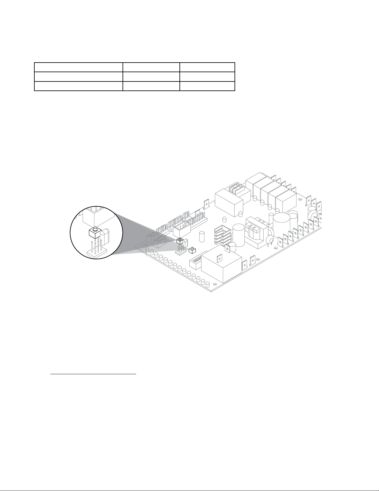
Fig. 1
1. Press the CLEAN button. The machine will drain. The
auger will run for a short time and then stop. Wait for
the LOW WATER light to come on.
LO WATER
8 HCE710A, HME710A
Fig. 2
2. Follow the directions on the SafeCLEAN Plus
packaging to mix 1 gal. (3.8 L) of Follett SafeCLEAN
Plus solution. Use 100 F (38 C) water.
3. Using a 1 quart (1L) container, slowly ll cleaning cup
until CLEANER FULL light comes on. Do not overll.
4. Soak one SaniSponge™ in remaining sanitizing and
cleaning solution and retain for Step 9.
Note: Do not use bleach to sanitize or clean the icemaker.
CLEANER FULL
Fig. 3
5. Replace cover on cleaner cup. Machine will clean,
then ush 3 times in approximately 15 minutes. Wait
until machine restarts.
15
Fig. 4
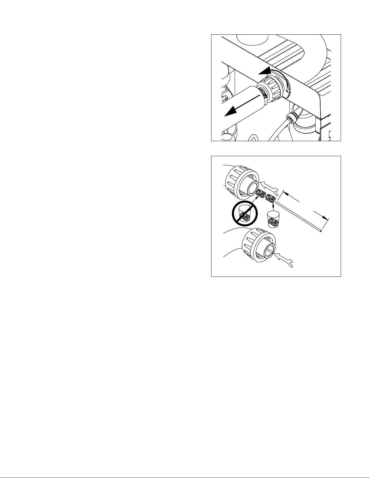
6. To clean/sanitize ice transport tube – Press power
switch OFF
HCE710A, HME710A 9
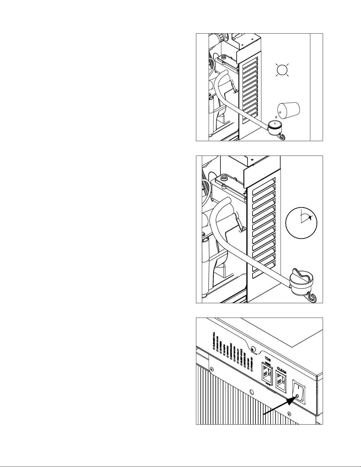
Fig. 5
7. Disconnect coupling as shown.
Fig. 6
8. Using disposable food service grade gloves, insert
dry SaniSponge.
9. Insert SaniSponge soaked in SafeClean Plus (from
Step 4).
10. Push both SaniSponges down ice transport tube with
supplied pusher tube.
1
2
3
16"
(407 mm)
10 HCE710A, HME710A
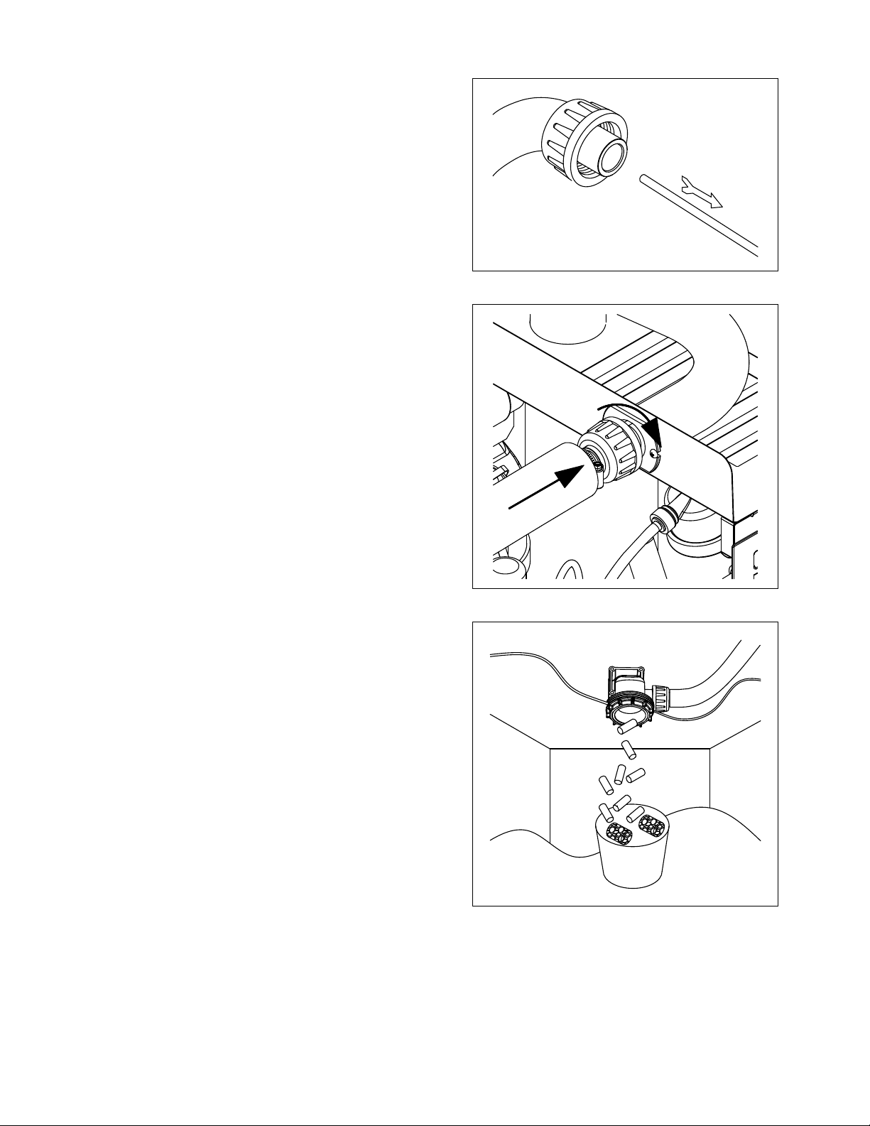
Fig. 7
11. Remove and discard 16 inch (407 mm) pusher tube.
Fig. 8
12. Reconnect coupling. Press power switch ON. Ice
pushes SaniSponges through ice transport tube.
Fig. 9
13. Place a sanitary (2 gal. or larger) container in bin
or dispenser to collect SaniSponges and ice for 10
minutes.
14. Collect 5.5 lbs (3 kg) of ice from unit. Discard ice and
SaniSponges.
HCE710A, HME710A 11
Service
Ice machine operation (all models)
Follett’s ice machine consists of ve distinct functional systems covered in detail as follows:
§ Water system
§ Electrical control system
§ Mechanical assembly
§ Refrigeration system
§ Bin full
The Horizon ice machine overview
The Follett Horizon ice machine uses a horizontal, cylindrical evaporator to freeze water on its inner surface. The
refrigeration cycle is continuous; there is no batch cycle. The evaporator is ooded with water and the level is
controlled by sensors in a reservoir. A rotating auger continuously scrapes ice from the inner wall of the evaporator.
The auger moves harvested ice through the evaporator into an ice extrusion canal. The ice is forced through a
restrictive nozzle that squeezes out the water and creates the Chewblet. The continuous extrusion process pushes
the Chewblets through a transport tube into a dispenser or bin.
A solid state PC board controls and monitors the functionality of the ice machine. In addition to sequencing
electrical components, the board monitors various operational parameters. A full complement of indicator lights
allows visual status of the machine's operation. Additionally, the PC board controls the self-ushing feature of the
ice machine. The evaporator water is periodically drained and replenished to remove minerals and sediment.
A unique “bin full” detection system is incorporated in the Horizon ice machine. A switch located at the ice
discharge port of the machine detects the position of the transport tube. When the bin lls up with ice, the transport
tube moves out of the normal running position, and the switch turns the ice maker off. A domed housing at the end
of the transport tube contains the ice extrusion loads during shut down.
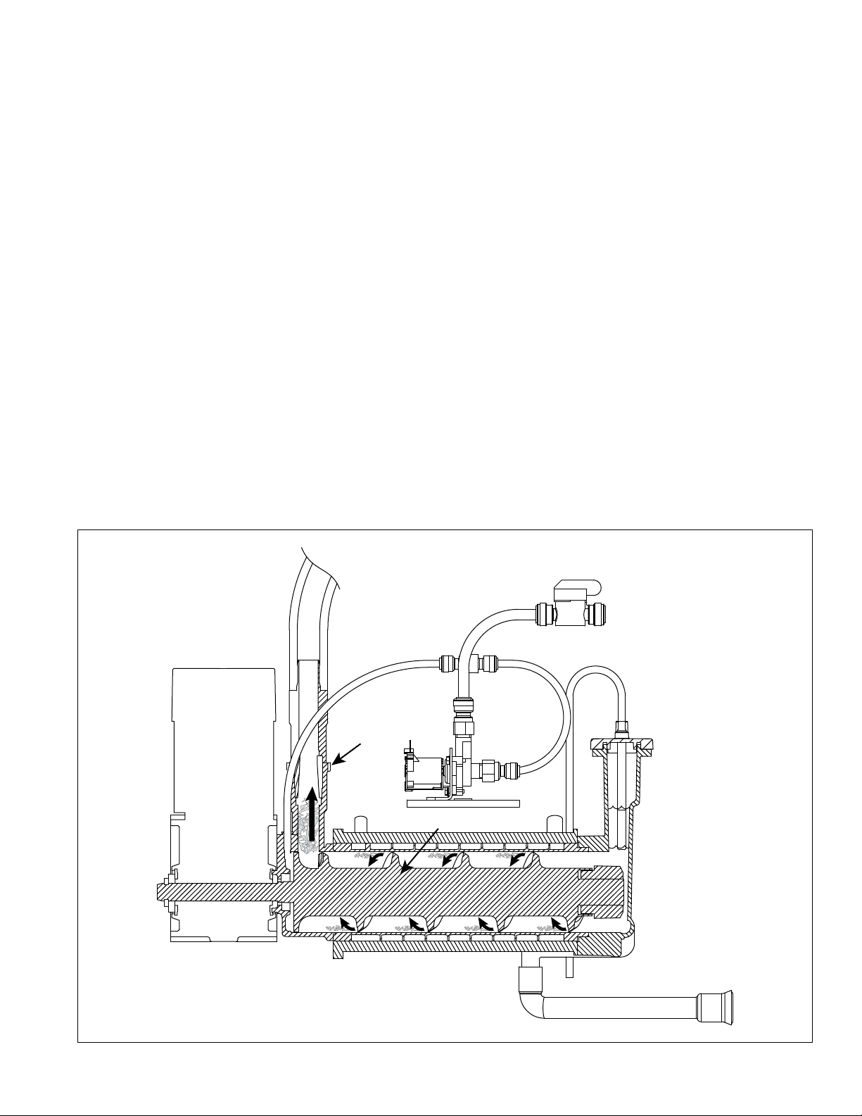
Harvest system diagram
Ice Transport Tube
Auger
Compression
Nozzle
Water Inlet
12 HCE710A, HME710A
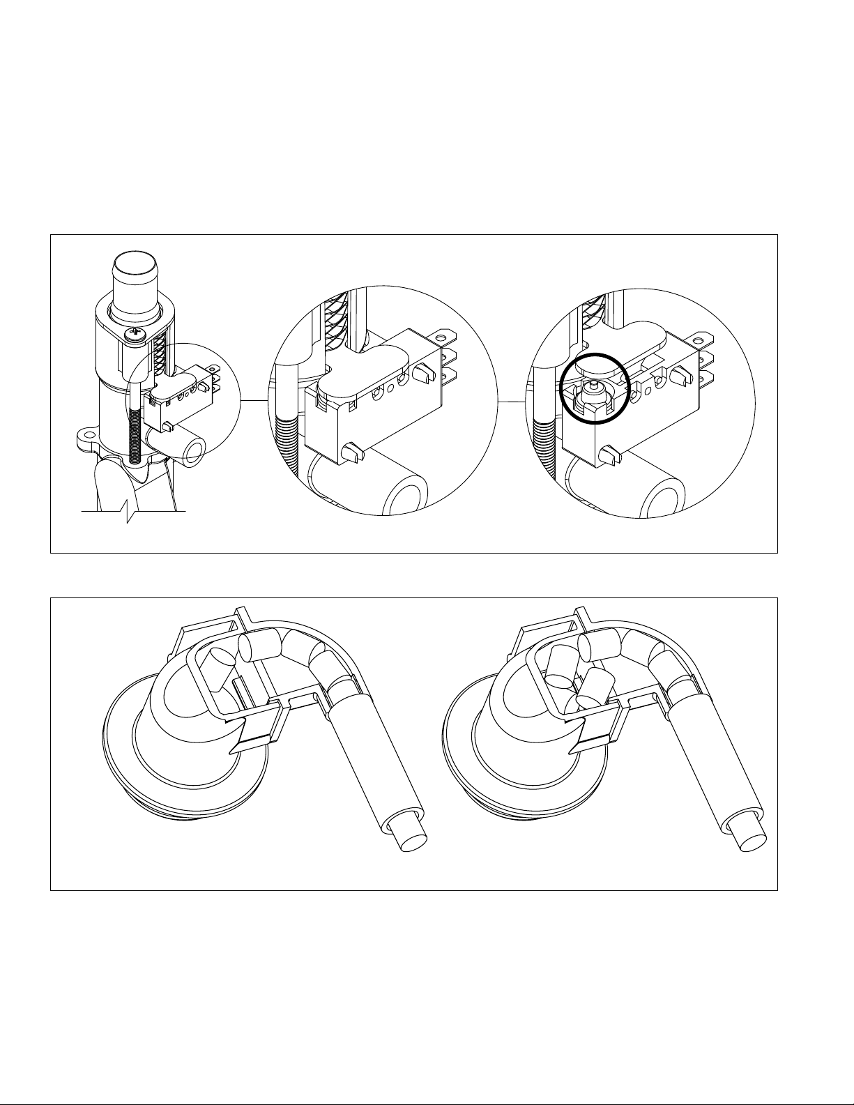
“Bin full” detection system
The Follett Horizon ice machine incorporates a unique “bin full” detection system that consists of the shuttle and
actuator. The shuttle incorporates a ag and switch. Referencing the gure below, the normal running position
of the ag is down, and the switch is closed. When the bin lls to the top and ice can no longer move through
the tube, the machine will force the shuttle ag up, opening the switch and shutting the machine off. The shuttle
actuator, located above the ice bin allows the ice to curl up within it when the bin is full. In this way, there are no
loads generated that would tend to lift off the lid of the bin.
Running Off
Running
Off
Shuttle ag and sensor
Shuttle actuator
HCE710A, HME710A 13
Water system
The water level in the evaporator is controlled by a feed solenoid and level detecting sensors. Referencing the
diagram below, water sensing probes extend down into the reservoir at the end of the evaporator assembly. The
system works via electrical conductivity as follows:
The probe labeled B is the common. When water is between any of the other probes and the common, the PC
board will sense the activation. During normal operation, the water level rises and falls between the Normal
High and Normal Low probes. As water is consumed to make ice, the level will fall until the Normal Low probe is
exposed, triggering the water feed solenoid on. Water will ll until the Normal High sensor is activated.
Note: The potable water total dissolved solids (TDS) content must be greater than 10 ppm for the water control
system to function properly. If using reverse osmosis water ltration system, ensure TDS level is greater than
10 ppm.
Water system diagram
Water level diagram
Common
Normal Hi
Normal Lo
Normal
Operating
Range
14 HCE710A, HME710A
Electrical system
ATTENTION!
To prevent circuit breaker/Hi-amp overload, wait 5 minutes before
restarting this unit. This allows the compressor to equalize and the
evaporator to thaw.
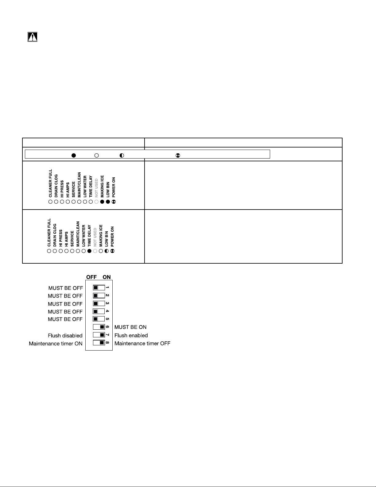
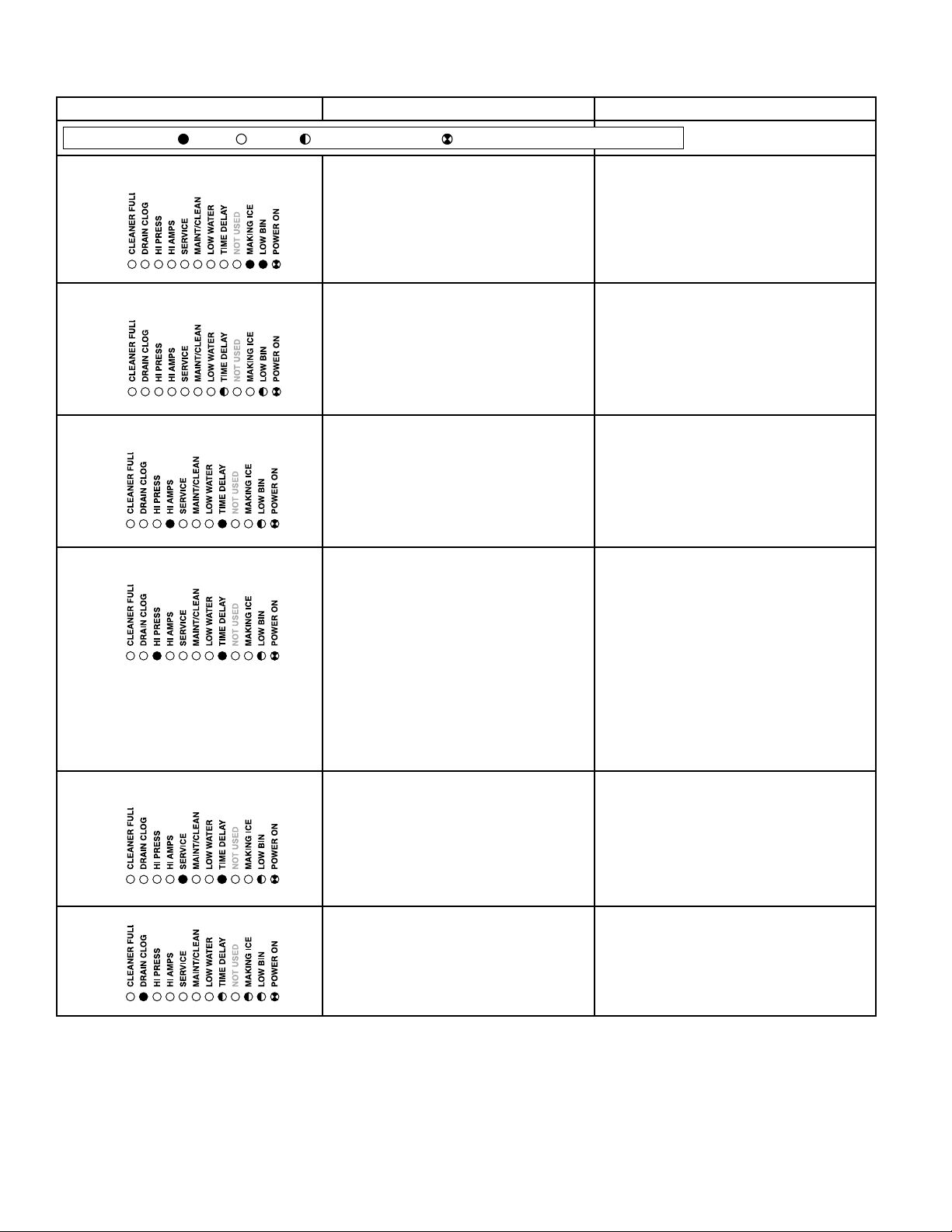
Normal control board operation
The PC board indicator lights provide all the information necessary to determine the machine's status. Green
indicator lights generally represent “go” or normal operation; Yellow indicators represent normal off conditions; Red
indicators generally represent alarm conditions, some of which will lock the machine off.
A ashing green light labeled POWER indicates power to the machine. All other normal operation status indicators
are covered as follows:
Ice machine disposition Operating conditions
FLASHINGON or OFF
Legend:
OFFON
1. Ice machine is making ice.
.
1. Normal running.
2. Ice machine is not making ice.
2. Normal time delay. When the bin lls with ice, the LOW BIN
light goes out momentarily and the refrigeration and auger
drive systems immediately shut down. (Note: The fan motor
will continue to run for 10 minutes to cool condenser) The TIME
DELAY light comes on, initiating the time delay period. When the
time delay expires, the machine will restart provided that the LOW
BIN light is on.
DIP Switch Settings

HCE710A, HME710A 15
Error faults:
The Horizon PC board monitors various operating parameters including high pressure, auger gearmotor amperage
limits, clogged drain, and low water alarm conditions. There are three types of errors namely “soft” (time delay)
"hard" (reset), and “run”.
§ Soft errors will automatically reset after the 1 hour time delay or can be reset by cycling power.
§ Hard errors must be reset on the control board.
§ Run errors will give an indication of a problem, but will allow continuous normal operation.
Soft errors:
HI AMPS: The PC board monitors the amperage of the auger motor. Should the gear motor experience current
draw above the allowable limit, the machine will shut down and the TIME DELAY and HI AMP will be illuminated.
After the time delay the machine will restart and the TIME DELAY and HI AMP will clear.
LO WATER: During operation, the water level cycles between the normal low and normal high sensors. Should the
water be shut off to a running machine, a soft error will occur. The error sequence is as follows: During operation,
the water level falls to the normal low sensor, and when it does the water feed solenoid is energized. If water is not
detected at the normal low sensor within 10 seconds, a soft error will occur. The machine will shut down, but the
water feed solenoid will remain energized. Should water return, it will ll to the normal low sensor and the machine
will resume normal operation. The error will clear automatically.
Water feed error: While in making ice mode, if the water level does not fall below the low probes for 9 minutes, the
machine will enter a 1-hour time delay soft error with the LOW WATER light ashing. After the time delay expires,
the machine will try to make ice.
HI PRESSURE: Should the refrigeration pressure rise above 425 psi, the machine will shut down and the TIME
DELAY and HIGH PRESSURE will be illuminated. After the time delay, and if the pressure has fallen back below
the reset point of 295 psi, the machine will restart and the TIME DELAY and HIGH PRESSURE will clear.
Hard error:
DRAIN CLOG: The drain clog sensor, located in the chassis will detect the presence of water just below the top
edge of the chassis. After the sensors are dried off, the machine must be reset on the control board to resume
operation.
Run errors:
DRAIN CLOG: When the machine shuts down on a full bin and there has been 30 minutes of cumulative
compressor run time, the machine will purge before starting. During this purge, if water does not get below the low
probe in the reservoir within 20 seconds, the Drain Clog LED will light. The machine will continue to run but this is
an indication of a poorly draining machine and must be addressed.
Relay output indication:
Each relay on the board has an indicator light associated with its output. For example, when the relay for the water
feed solenoid is energized, the adjacent indicator light glows green.
Evaporator ushing sequence:
During operation, the purge solenoid will open in order to drain water. There are two drain settings to choose from:
High TDS or Low TDS. (There is a rocker switch behind the front cover of the machine.) The intent is to drain the
Total Dissolved Solids from the machine while it makes ice.
While ice is being made, the TDS of the water in the evaporator increases in TDS concentration. Without periodic
draining, the TDS levels will climb to very detrimental levels, levels that will cause scale to form and cause poor
machine operation. The Low TDS setting will allow the machine to operate for one hour before going through the
ushing sequence; the High TDS setting will allow the machine to run for 11 minutes before going through the
ushing sequence.
The ushing sequence toggles the purge and ll solenoids three times. That is, the purge solenoid will energize
until the water level drops below the low probe. The ll solenoid then energizes until water reaches the high probe,
and so on for 3 cycles.
Typically, High TDS might be considered levels above 200 PPM, but local experience and varying water chemistry
may compel a High TDS setting for best performance in even lower TDS levels.
Off cycle: At the completion of off-cycle time delay, the machine checks for a cumulative 30 minutes of ice making
time since the last off-cycle ush. If the cumulative ice making time exceeds 30 minutes, the machine will open
the drain valve for 60 seconds to drain the evaporator in its entirety. It will then rell with water and begin making
ice. If the ice making time is less than 30 minutes, the machine will start and begin making ice without draining the
evaporator.
16 HCE710A, HME710A
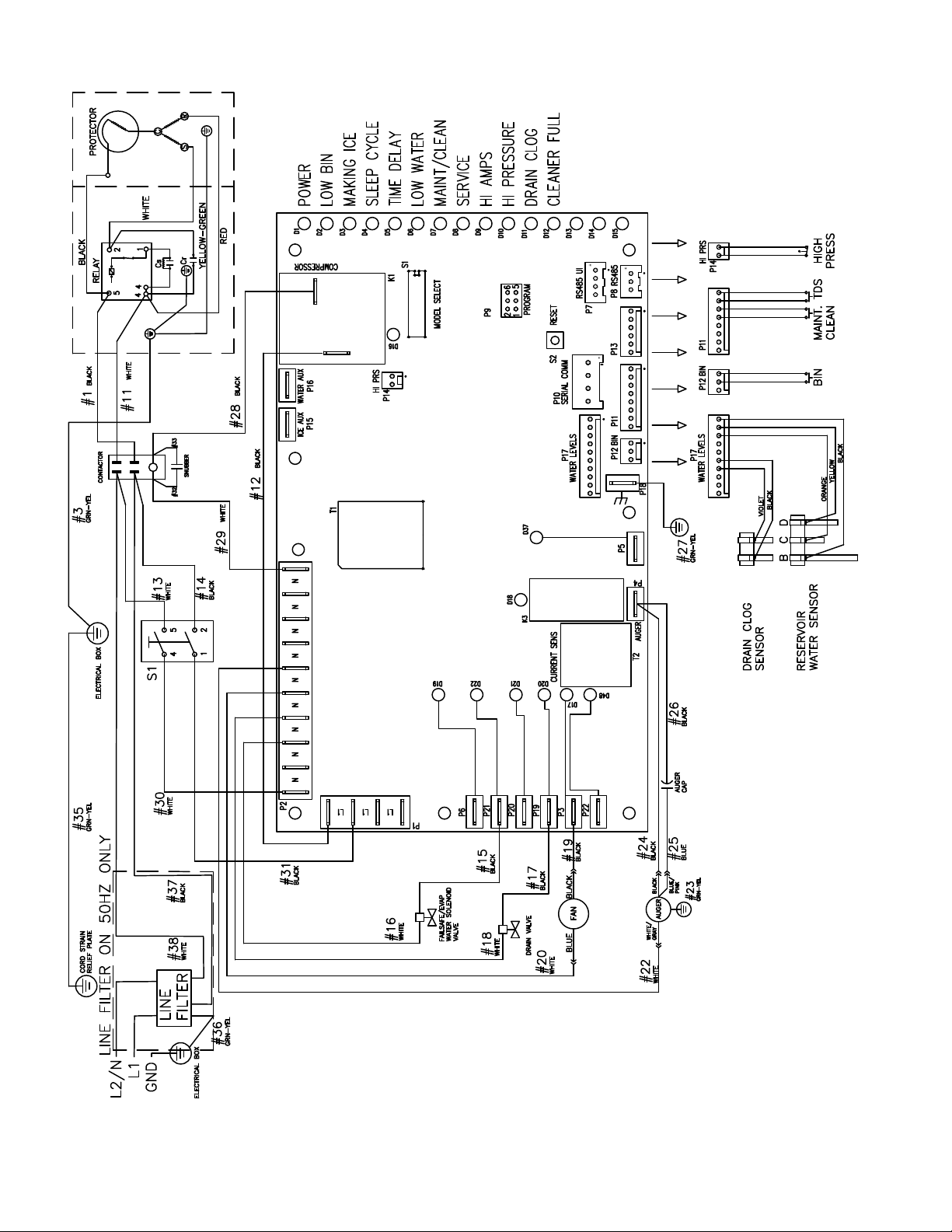
Wiring diagram

HCE710A, HME710A 17
Compressor data
230 V
Compressor current draw at 120 V VAC, 90 F/32.2 C
1.9A
Locked rotor amps @
120 V
21.0A
Compressor start winding
120 V
11Ω
Compressor run winding
120 V
5.15Ω
Gearmotor data
Gearmotor current
0.8 @ 230 V
Gearmotor torque-out (high amp) trip point:
1.2 @ 230 V
Resistance of windings
230 vac gearmotor:
White to black: 62Ω
White to tan: 62Ω
Tan to black: 124Ω
Fan motor data
Fan motor current 0.2A @ 230 V
18 HCE710A, HME710A
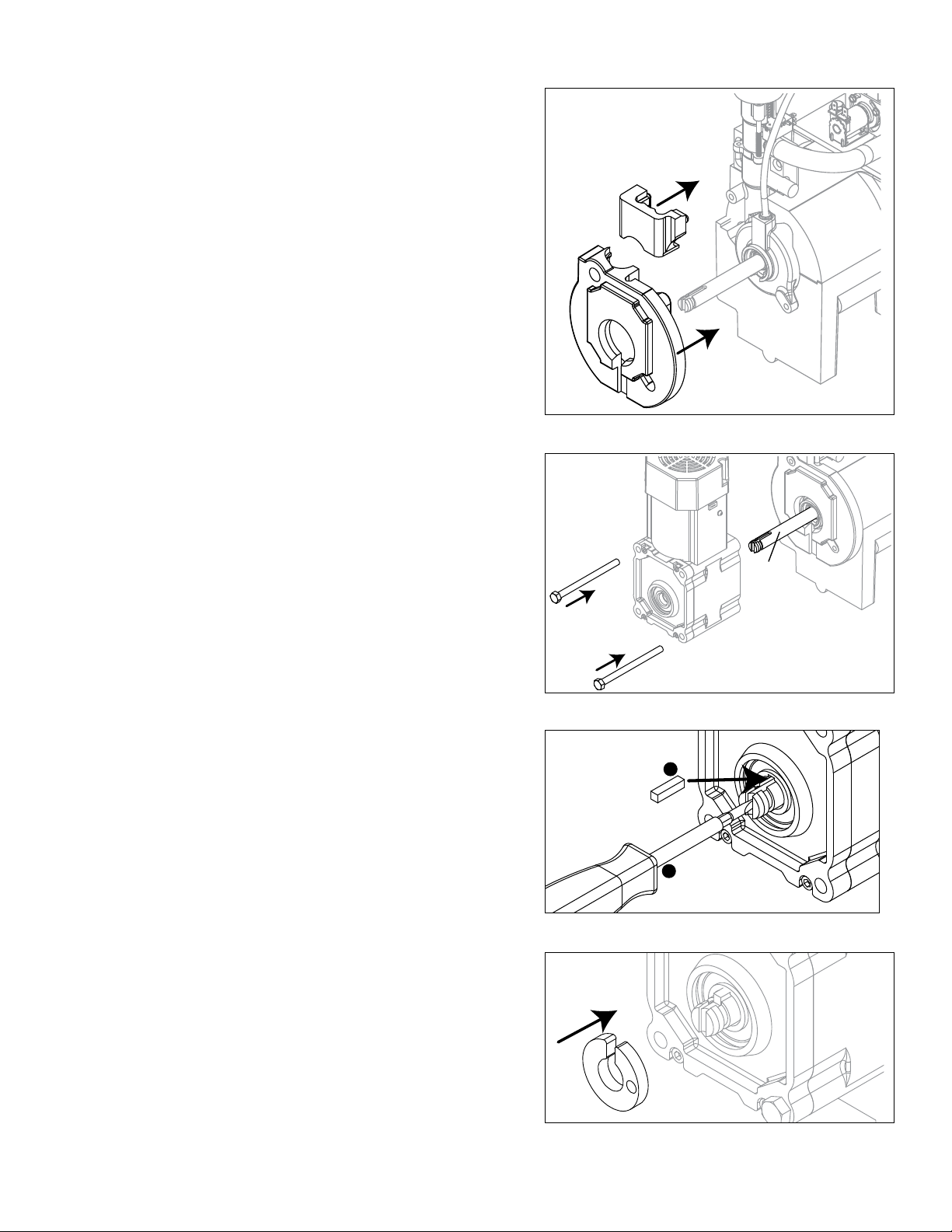
Mechanical System
Fig. 10
Evaporator disassembly
1. Press CLEAN button to purge evaporator. Turn power
OFF when LO WATER lights.
2. Unscrew and disconnect transport tube from louvered
docking assembly.
Fig. 11
3. Remove gear motor insulation.
Fig. 12
4. Disconnect gear motor wires and ground.
Fig. 13
5. Remove screws (with 3/16" allen wrench) and auger
retaining fork:
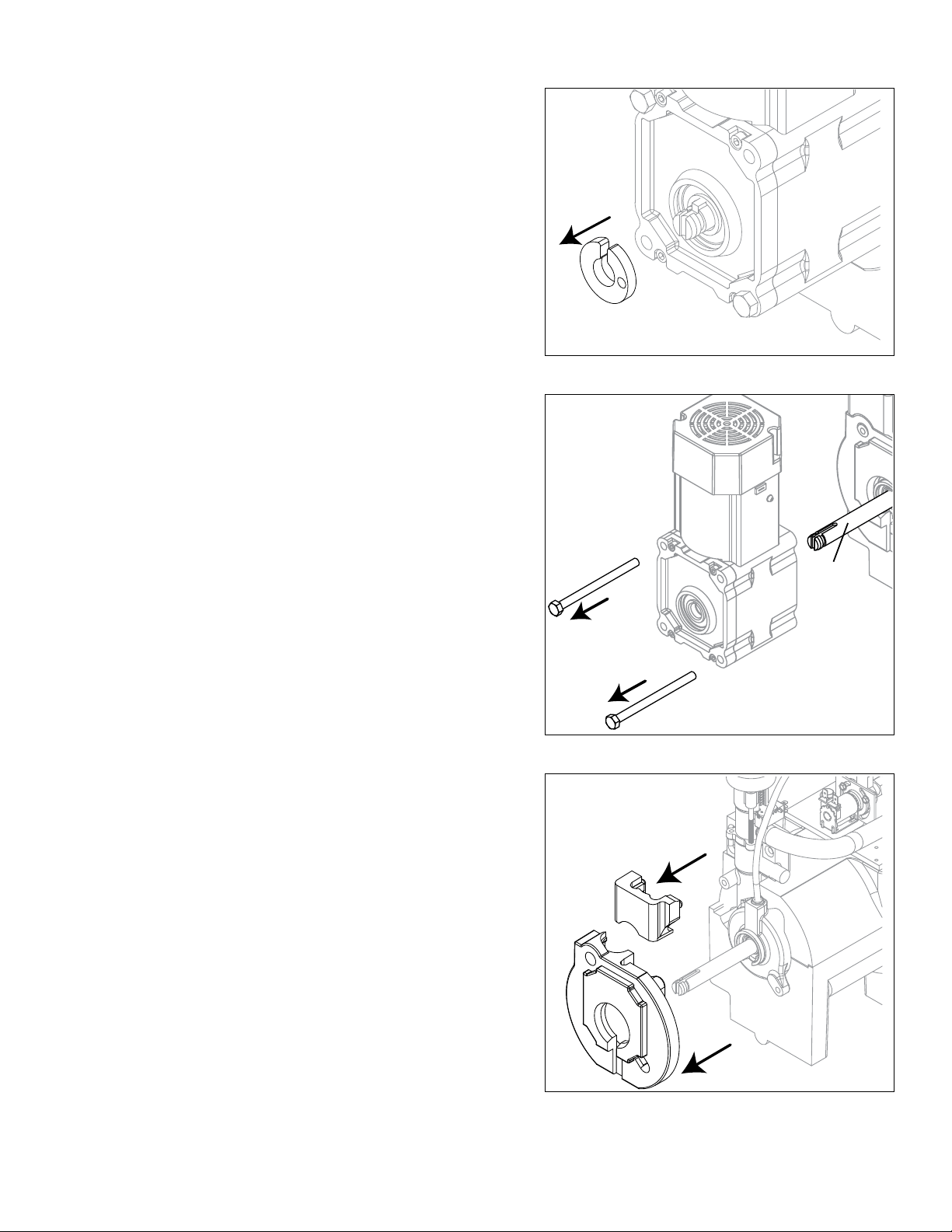
HCE710A, HME710A 19
Fig. 14
6. Remove spacer:
Fig. 15
7. Remove gear motor bolts (1/2" wrench).
8. Remove gear motor and wipe auger shaft clean.
WIPE
AUGER
SHAFT
Fig. 16
9. Remove main housing insulation and shuttle
insulation.
20 HCE710A, HME710A
Fig. 17
10. Remove front feed water tube from push-in tting,
shuttle drain tube, and shuttle switch.
Fig. 18
11. Remove 3 screws (with 3/16" allen wrench) then
remove auger and main housing together.
Note: Auger is sharp - wear protective gloves.
Fig. 19
12. Rotate auger to align opening in auger ange with
stream divider.
13. Pull out auger.
HCE710A, HME710A 21
Fig. 20
14. OPTIONAL: Remove and discard the ceramic mating
ring and shaft seal as necessary.
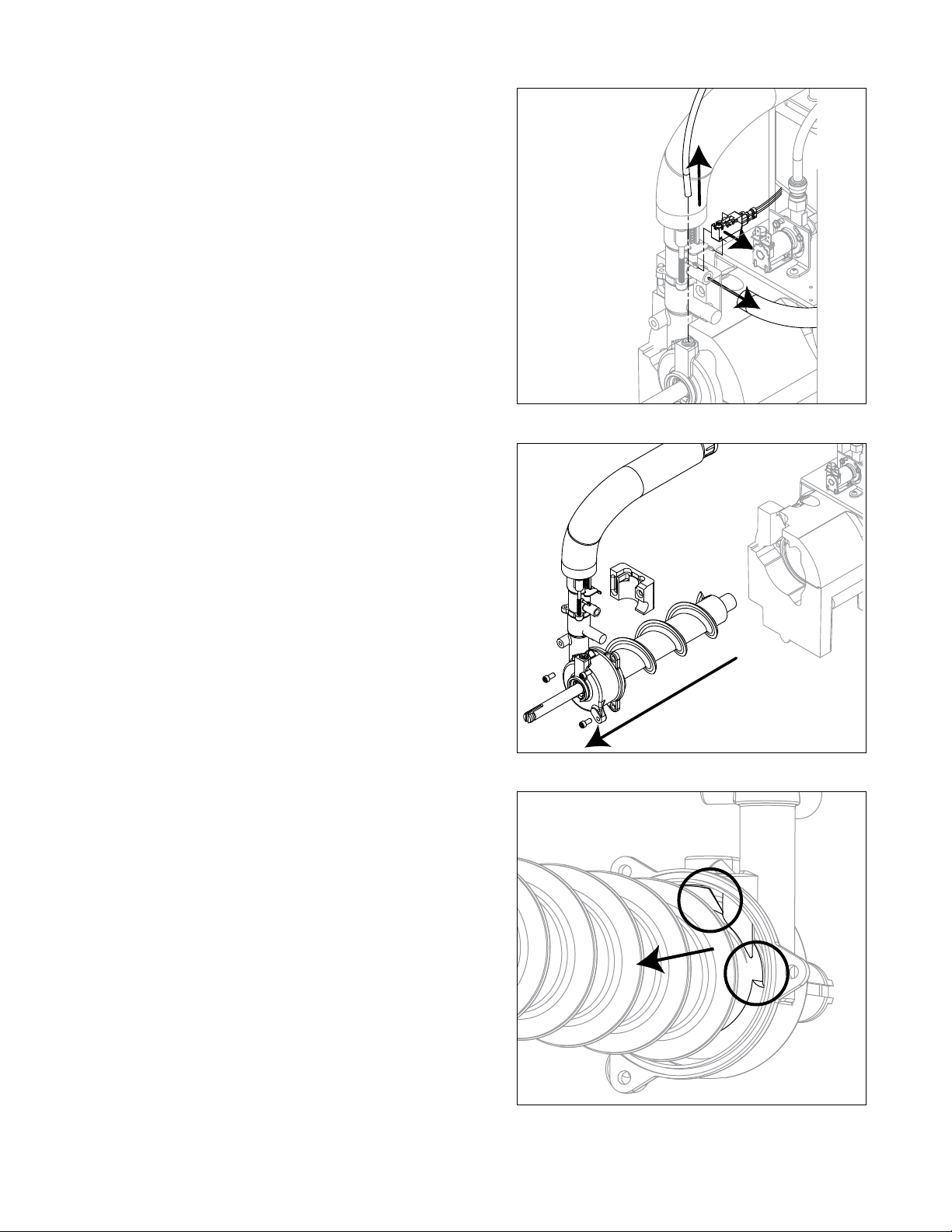
Evaporator reassembly
Fig. 21
15. If removed prior, install ceramic mating ring and shaft
seal.
Caution: Do not touch the sealed surface of either part.
Oil from bare skin will cause premature seal failure.
16. Use liquid hand soap on the rubber part of the
ceramic seal when installing in main housing. Use
supplied cardboard disc to press into recess.
1 7. Apply liquid hand soap to raised area of auger
shaft and interior rubber portion of shaft seal before
installing seal.
18. Clean O ring groove. Lubricate O ring with petrol-gel
and reinstall.
Cardboard
disc
Do NOT
touch!
Fig. 22
19. Carefully install auger.
20. Rotate auger to position shown to clear main housing
stream divider.
22 HCE710A, HME710A
Fig. 23
2 1. Install rear shuttle insulation (Fig. 23.1) and slide
main housing (Fig. 23.2) onto auger.
22. Secure with three screws.
1
2
Fig. 24
23. Install shuttle switch.
§ Align holes with pins (Fig. 24.1) and depress switch
button (Fig. 24.2) to clear shuttle tab.
Fig. 25
24. Install shuttle drain tube and front feed water tube
(Fig.25).
Note: Ensure water feed tube is inserted 5/8".
HCE710A, HME710A 23
Fig. 26
25. Install main housing insulation and shuttle insulation:
Fig. 27
26. Apply a coat of petrol-gel to auger shaft.
2 7. Slide gear motor onto auger and install gear motor
bolts (1/2" wrench).
APPLY
PETROL-GEL
Fig. 28
28. Use screwdriver to pry auger shaft foward, then
orient auger shaft to align with motor shaft keyway
(Fig. 28.1).
29. Install key fully into keyway (Fig. 28.2).
1
2
3
Fig. 29
30. Install spacer, ensure that key is captured in slot.
24 HCE710A, HME710A
Fig. 30
3 1. Insert screwdriver into groove of auger shaft and pry
shaft outwards (Fig.30.1).
32. Insert retainer into groove (Fig.30.2), ensure that
retainer is aligned with hole in spacer.
1
2
Fig. 31
33. Install screw and tighten (Fig.31.1).
1
Fig. 32
34. Connect gear motor wires and ground wire.
WHITE
GRAY
GROUND SCREW
HCE710A, HME710A 25
Fig. 33
35. Install gear motor insulation.
Fig. 34
36. Connect transport tube to louvered docking assembly.
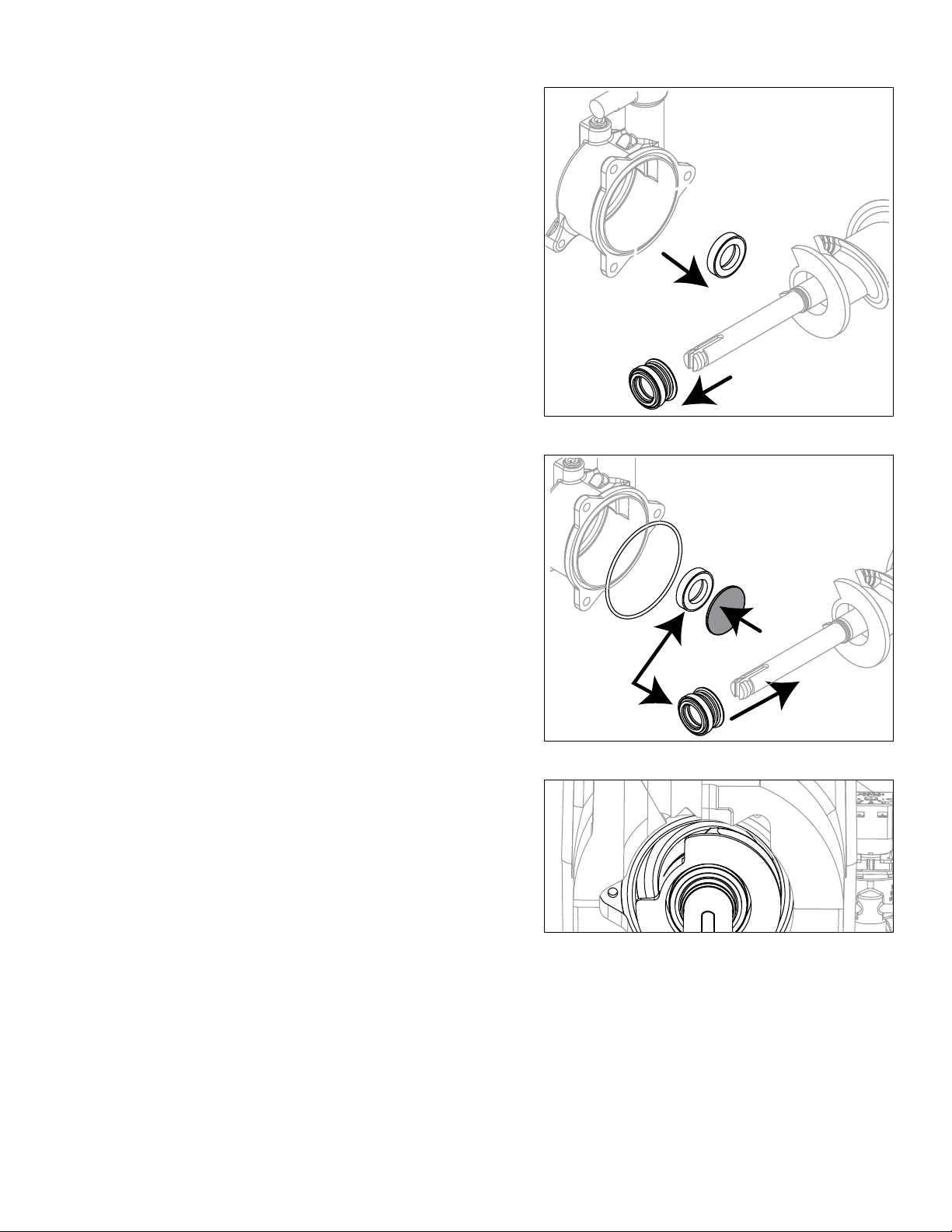
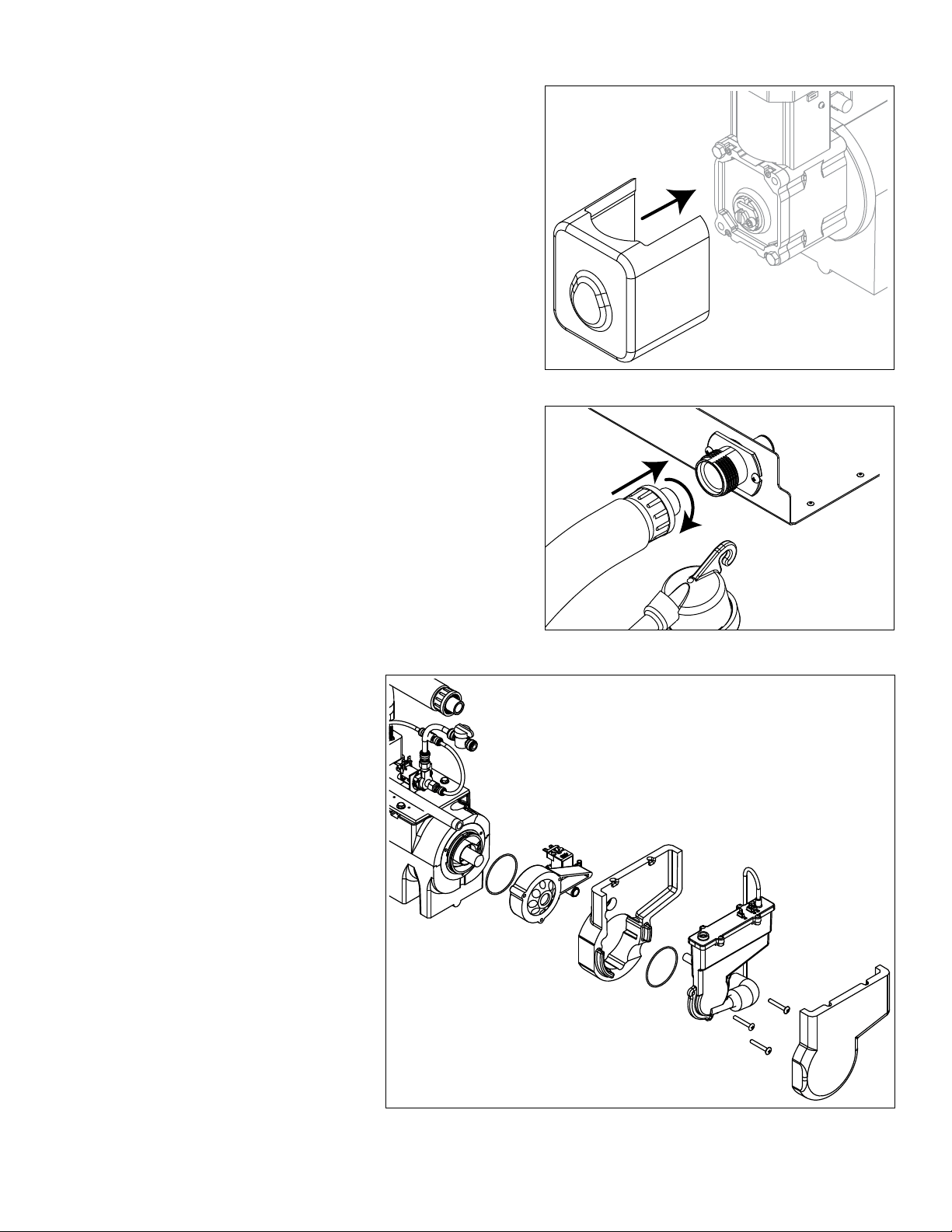
Reservoir/rear bushing disassembly
Fig. 35
1. Press CLEAN button to purge
evaporator. Turn power OFF
when LO WATER lights.
Note: In many applications,
removing the gearmotor,
main housing, and
auger will allow for
the ice machine to be
pulled out further for
better access to rear
components.
2. Slide ice machine forward to
gain access.
3. Use Fig. 35 as disassembly
guide.
Note: Use petrol-gel when
installing/reinstalling
o-rings.
26 HCE710A, HME710A
Refrigeration system
Refrigerant pressure data
Air-cooled condensers (air) 60 F/16 C 70 F/21 C 80 F/27 C 90 F/32 C 100 F/38 C
Pressure (psig) discharge/suction 180/17 195/19 225/22 256/24 310/26
Refrigeration charge
All service on refrigeration systems must be performed in accordance with all federal, state and local laws. It is the
responsibility of the technician to ensure that these requirements are met. Recharging ice machine to other than
factory specications will void the warranty.
R404A ice machine charge specications
Model Charge Refrigerant type
E710A (air-cooled) 24 oz (680 g) R449A
Refrigeration system diagram
HCE710A, HME710A 27
Evacuation
Evacuate the system to a level of 500 microns. When the 500 micron level is reached, close all valves. Allow the
system to sit for approximately 20 minutes. During this period the system pressure should not rise. If the system
pressure rises and stabilizes there is moisture in the system and further evacuation is needed. If the pressure
continues to rise check the system for leaks.
Ambients Minimum Maximum
Air temperature
1
50 F/10 C 100 F/37.8 C
Water temperature
2
45 F/7 C 90 F/32.2 C
1
Ambient air temperature is measured at the air-cooled condenser coil inlet.
2
Ambient water temperature is measured at the water feed valve inlet.
Ice capacity test
Ice machine production capacity can only be determined by weighing ice produced in a specic time period.
1. Replace all panels on ice machine.
2. Run ice machine for at least 15 minutes.
3. Move TDS switch to LOW.
4. Press the reset button on the board.
5. Weigh and record weight of container used to catch ice.
6. Catch ice for 15 minutes.
7. Weigh harvested ice and record total weight.
8. Subtract weight of container from total weight.
9. Convert fractions of pounds to decimal equivalents (ex. 6 lbs 8 oz = 6.5 lbs).
10. Calculate production using following formula:
1440 min. x wt. of ice produced
Total test time in minutes
=
Production capacity/24 hr.
11. Calculated amount per 24 hours should be checked against rated capacity for same ambient and water
temperatures in Ice Production Tables.
12. Move TDS switch to the HI TDS position.
28 HCE710A, HME710A
Troubleshooting
Please see “Service” section for a description of each function.
Ice machine disposition Possible causes Corrective action
FLASHINGON or OFF
Legend:
OFFON
1. Ice machine is in running
condition but not making ice.
.
1. Defective compressor.
2. Defective start relay.
3. Defective start capacitor.
4. Defective run capacitor.
5. Defective main contactor.
6. No output from PC board.
1. Replace compressor.
2. Replace start relay.
3. Replace start capacitor.
4. Replace run capacitor.
5. Replace main contactor.
6. Replace PC board.
2. Machine in TIME DELAY without full
bin.
1. Ice jamming due to improperly
installed transport tube causing a false
shuttle.
2. Shuttle stuck in up position.
3. Damaged or improperly installed
thermostat (open).
4. Transport tube backed-out of coupling.
1. Correct transport tube routing.
2. Repair or replace shuttle mechanism.
3. Replace or reposition thermostat.
4. Correct coupling installation.
3. Ice machine is not making ice.
HI AMPS.
.
1. Poor water quality causing ice to jam
auger.
2. Damaged shuttle mechanism.
3. Intermittent drive output from
PC board. Evaporator will freeze
causing a HI AMPS error.
4. Gearmotor is unplugged.
1. Clean ice machine. Increase
ushing frequency. Position TDS switch
to High TDS setting.
2. Replace or repair shuttle
mechanism.
3. Replace PC board.
4. Plug in gearmotor.
4. Ice machine is not making ice.
HI PRESSURE.
.
1. High ambient temperatures
>100 F (38 C).
2. Poor ventilation or air recirculation.
3. Clogged condenser (air-cooled).
4. No water ow through condenser
(water-cooled).
5. Fan not working properly. No
air ow.
• Blocked fan blades
• No fan output from PC board
• Faulty fan motor
1. Air condition area to below 100F
(38 C).
2. Reposition ice machine or properly
ventilate. Prevent ice machine exhaust
from recirculating.
3. Clean condenser grille (air-cooled).
4. Restore water ow to condenser.
5. Correct air ow.
• Remove any blockage from fan
blades
• Replace PC board
• Replace fan motor
5. Ice machine is not making ice.
SERVICE.
.
1. Internal water leak touching chassis
sensor.
1. Identify and repair leak. Clean/dry
chassis and sensors and restart
machine.
6. Drain clog.
.
1. Improper ow in drain system. 1. Correct/clean drain system.
HCE710A, HME710A 29
Ice machine disposition Possible causes Corrective action
FLASHINGON or OFF
Legend:
OFFON
7. Ice machine is making ice.
Excessive water in bin or
coming into bin from transport
tube.
1. Failed water sensors. Processor
assumes there is no water when
there is water.
2. Blocked reservoir vent.
3. Defective water feed solenoid
valve. Stuck in open position.
1. Clean or replace water probe
assembly. Check wiring
connections.
2. Clean or replace vent tubes.
3. Replace water feed solenoid
valve.
8. Ice machine is not making ice.
Low Water.
1. Water supply is insufficient.
2. Low water pressure.
3. Defective water feed solenoid
valve. Stuck in closed position.
4. No water feed output from
PC board.
5. Plugged screen on inlet side of ll
solenoid.
6. Plugged check valve.
1. Restore water supply and check
water lters. If evaporator was
completely empty the reset button
may have to be pressed to restart
the ice machine.
2. Ice machine will eventually start
when water reaches normal lo
level.
3. Replace water feed solenoid valve.
4. Replace PC board.
5. Remove and clean screen.
6. Remove and clean.
9. Blinking Low Water, power, time
delay.
Machine did not see water
consumption while trying to make
ice.
1. Lack of refrigeration/low
refrigerant charge/leak.
2. Debris shorting reservoir probes.
1. Verify refrigerant pressures,
compressor running, sight glass
clear.
2. Clean probes and reservoir of
debris.
ATTENTION!
To prevent circuit breaker overload, wait 5 minutes before restarting
this unit. This allows the compressor to equalize and the evaporator
to thaw.
30 HCE710A, HME710A
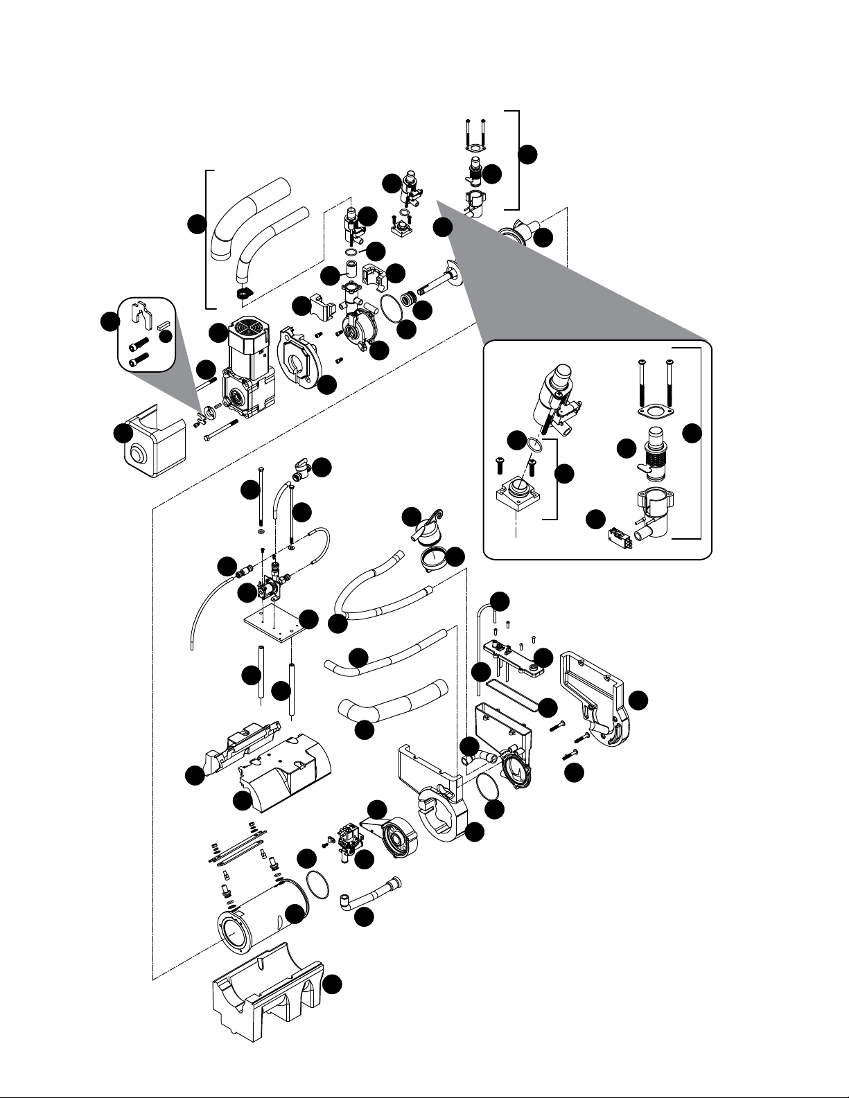
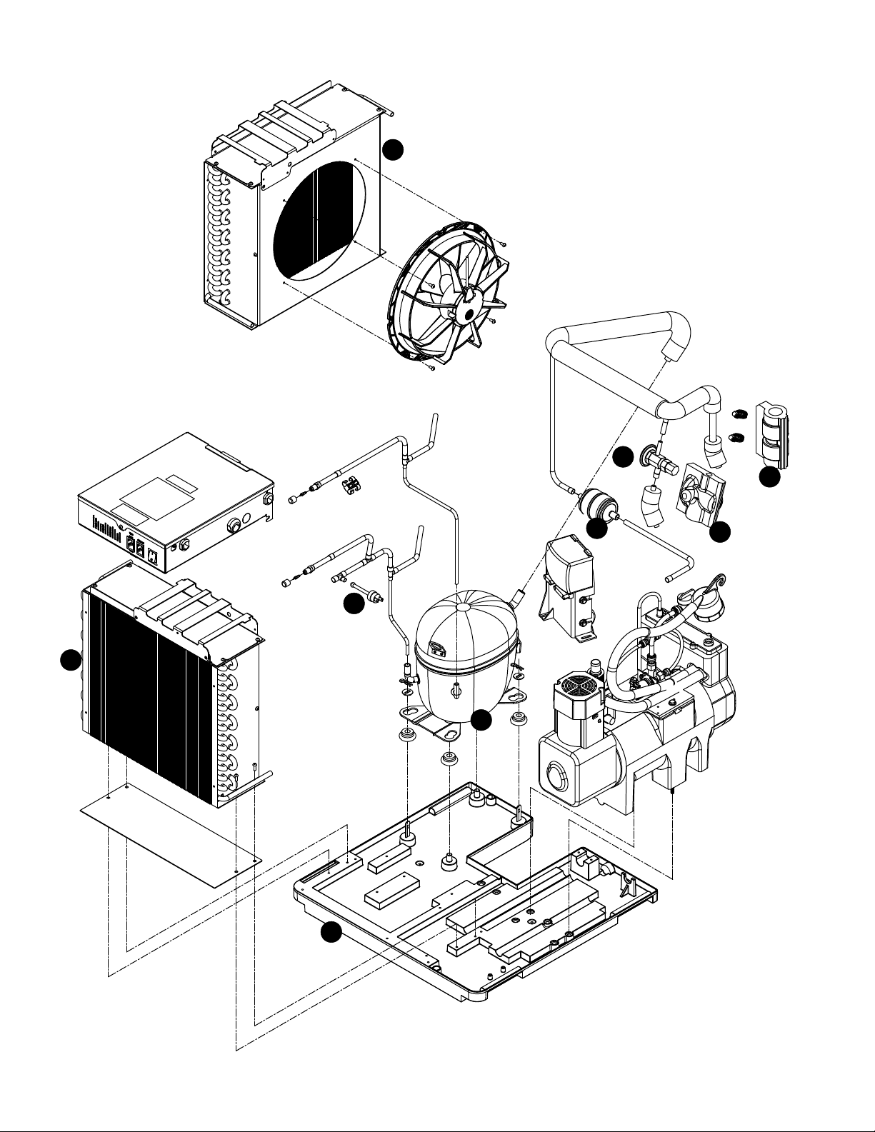
Replacement parts
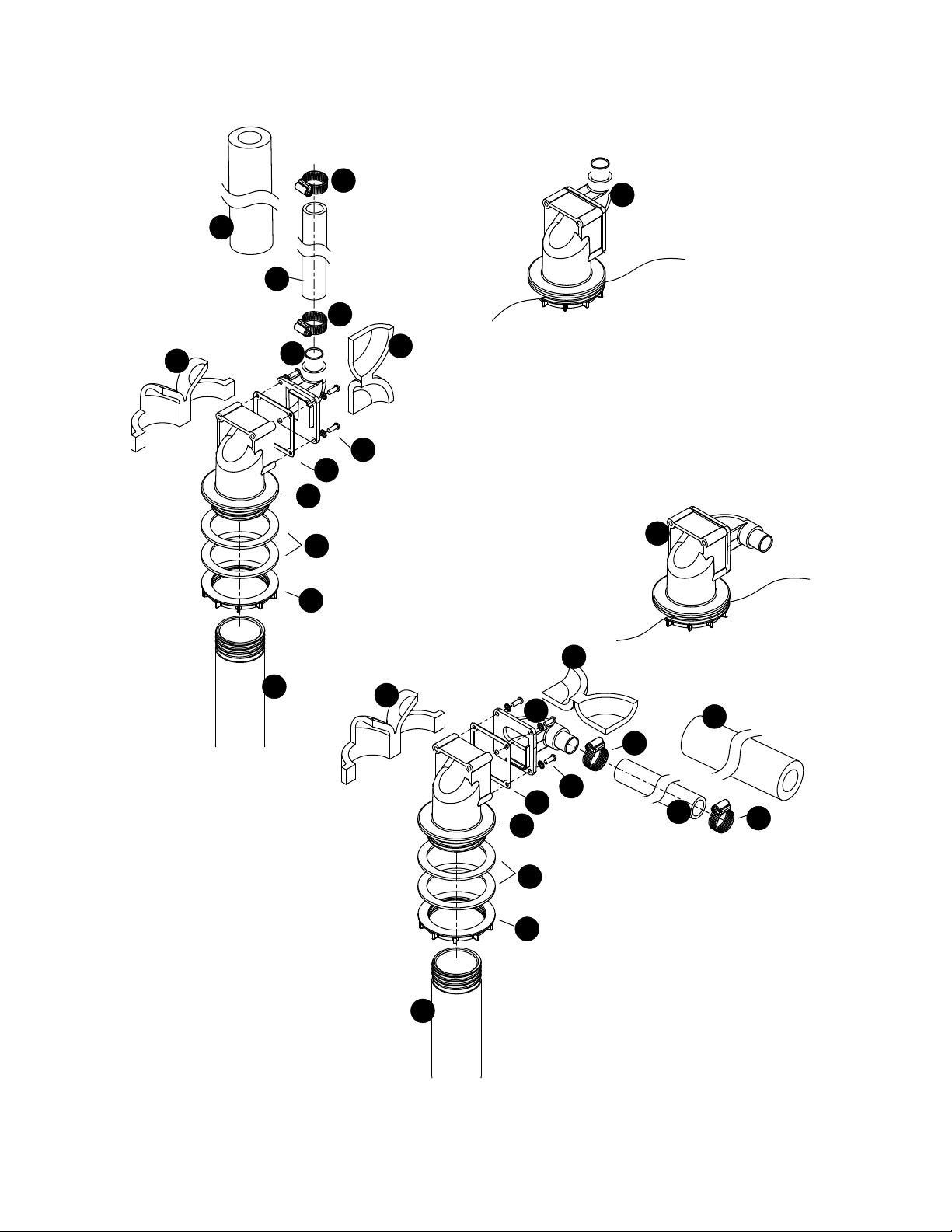
Evaporator assembly
27
3
35
10
2
8
3
21
5
2
1
14
13
12
11
9
30
7
20
15
16
18
22
23
30
30
30
30
30
19
13
24
25
26
28
28
4
10
2
30
17
17
17
17
17
33
32
33
29
31
2
30
30
6
13
HCE710A, HME710A 31
Reference # Description Part #
1 Tube, ice transport, insulated 0111818 1
2 Shuttle assembly 0111813 2
3 Switch, shuttle 01006261
4 Compression nozzle 01222744
5 O-ring, shuttle 01164920
6 Screw, reservoir (10 pack)
01333830
7 Auger hardware (includes screws, key, retainer) 01222744
8 Key (2) 01348101
9 Bolt, gearmotor mounting (2) (self-contained units), includes washers 01118629
10 Cartridge assembly, shuttle spring 01118033
11 Gearmotor, (includes capacitor) 01006238
12 Main housing, self-contained 01222736
13 O ring 01248368
14 Seal, auger shaft 01333806
15 Cup, cleaner 01164995
16 Cap, cleaner 01118637
Not shown Tubing, water, 3/8" OD 502719
Not shown Tubing, water, 1/4" OD 502079
17 Retainer kit, evaporator 01223023
18 Solenoid, water feed 01301688
19 Reservoir lid and sensors (includes screws and o-ring) 0111810 8
20 Valve, shut-off, water 502921
21 Auger, 710 self-contained (includes seal, key, and auger hardware) 01222686
22 Evaporator, 710 01222694
23 Rear bushing housing and bushing (includes (1) o-ring) 01222710
24 Reservoir assembly, water (includes lid) 01222728
25 Tube, vent (17" required) 502079
26 Tube, cleaner 01118660
27 Kit, MicroChewblet 01161843
28 Tube, shuttle drain, insulated 01118678
29 Solenoid, purge 01148733
30 Insulation kit, 710 evaporator/reservoir 01222769
31 Check valve 01122381
32 Tube, drain, reservoir, insulated 0111812 4
33 Tube, drain, 710 01099662
34 O-ring, reservoir lid 01302298
Not shown Kit, scale (includes reservoir, purge solenoid, drain tubes and tting) 01122654
35 O-ring, MicroChewblet 01161850
Not shown Drain kit (includes 2 ft. x 1" OD silicone tubing, 3/4" x 1" slip, 3/4" barb 3/4" FPT
(2), 3/4" barb x 3/4" FPT elbow)
01210350
32 HCE710A, HME710A
8
1
7
6
4
5
3
2
4
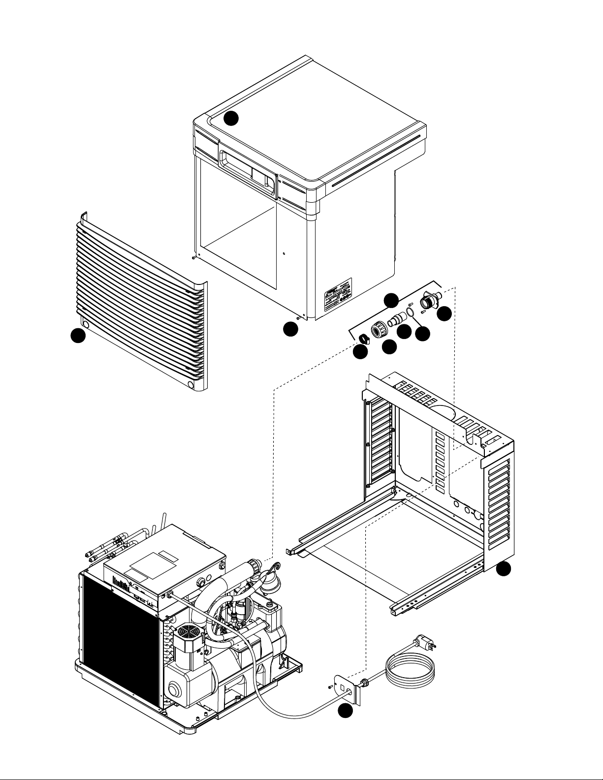
Air-cooled assembly
HCE710A, HME710A 33
Reference # Description Part #
1 Condenser 01222785
2 Fan motor assembly 01351725
3 Cut-out, high pressure safety 01232941
4 Insulation, TXV (body and bulb) 01444058
5 Drier 01153683
6 Valve, expansion, thermal (includes insulation and (2) clamps) 01444066
7 Compressor, (includes start/run components and drier) 01351733
8 Base, ice machine 01333772
34 HCE710A, HME710A
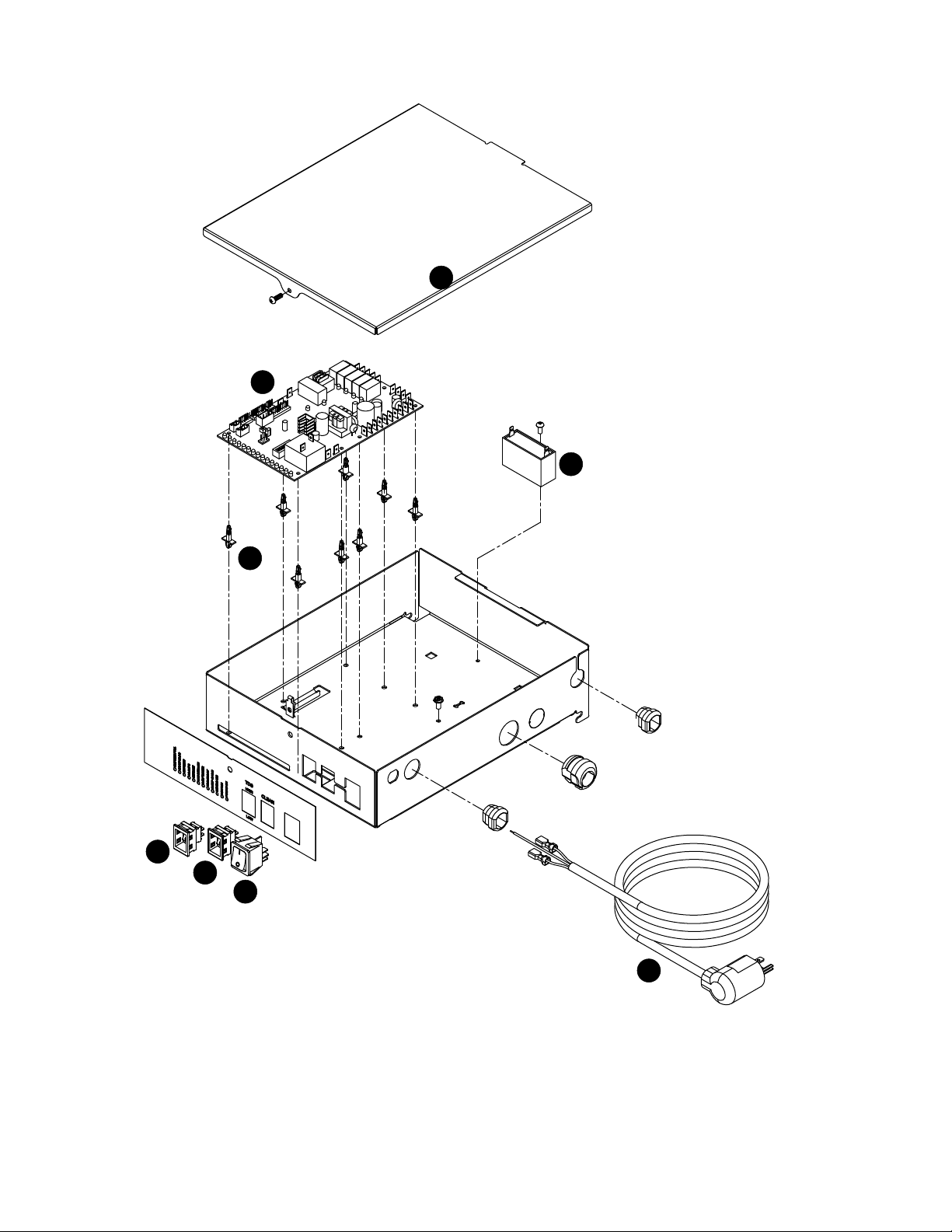
Electrical box
1
4
3
2
7
5
6
8
HCE710A, HME710A 35
Reference # Description Part #
1 Cover, electrical box, air/water-cooled 01118967
2 Board, control (includes stand-offs) 01375898
3 Stand-offs (set of 8) 00130906
4 Included with gear motor only
5 Switch, evaporator clean 01165703
6 Switch, ice machine power 01165711
7 Switch, TDS 01165695
8 Cord, power 01215672
Not shown Electrical line lter 01444074
Not shown Start components 01444041
Not shown Contactor 00917195
36 HCE710A, HME710A
Integration kit – top-mount and RIDE remote ice delivery
1
11
2
2
13
10
12
4
5
7
8
12
1
11
10
2
9
4
5
6
7
8
2
6
3
3
RIDE model configuration
Top mount configuration
14
14
HCE710A, HME710A 37
Reference # Description Part #
1 Shuttle actuator 00171322
2 Clamp 500377
3 Actuator elbow (includes 00167122 and 209100) 00171264
4 Screws 01303064
5 Gasket 01303072
6 Actuator body 00171272
7 Gasket, coupling 01303080
8 Ring, locking (includes 00126532) 00171371
9 Ice transport tube, 10' (3 m) 00171280
9 Ice transport tube, 20' (6 m) 00171298
10 Insulation, transport tube 501176
Not shown Insulated polywire ice transport tube, per foot 00174896
11 Insulation, elbow 01303098
12 Insulation, actuator 01303106
13 Ice transport tube, top mount, 30" (762 mm) 00171306
14 Extension-ll tube, 9" 01303114
14 Extension-ll tube, 4" 01303122
Not shown Integration kit, top mount, Harmony or Bin 00171389
Not shown Integration kit, RIDE model, Harmony or Bin, (includes 10' (3 m) of tube and
insulation)
00171397
Not shown Integration kit, drop in 00145334
Not shown Integration kit, Cornelius PR150 00144774
Not shown Integration kit, Vision (does not include ice tube) 00997171
Not shown Diverter plate (single agitator Cornelius dispensers and left-hand dispense chute on
dual-agitator Cornelius dispensers)
01303130
Not shown Diverter plate (right-hand dispense chute on dual-agitator dispensers) 00996207
Not shown SafeCLEAN Plus, case of 6 01149954
Not shown SafeCLEAN Plus, case of 24 01149962
Not shown SaniSponge kit 00132068
Not shown High-capacity lter system 01303148
Not shown Primary lter (1) 01333814
Not shown Primary lter (6) 00978973
Not shown Pre-lter (1) 01333822
Not shown Pre-lter (12) 00954305
Not shown IMS III sanitizer concentrate - 16 oz. 00979674
Not shown Sponge, sanitary, pack of 24 01075431
Not shown Kit, IMDV (included IMDV cartridge and communication cable) 01116177
Not shown Tubing, silicone (per foot) 01303155
38 HCE710A, HME710A
Skins assembly
9
8
10
2
1
11
7
5
4
3
6
HCE710A, HME710A 39
Reference # Description Part #
1 Grille, front 01303163
2 Front cover, air-cooled, 710/710 01119007
Not shown Tubing, water, 3/8" OD 502719
3 Coupling (includes O-ring) 00171207
4 O-ring 01303171
5 Bulkhead tting 00171215
6 Nut 01303189
7 Hose clamp 500377
8 Plate, strain relief 00192070
9 Louvered docking station, 710 (includes strain relief plate, bulkhead tting) 01119031
10 Screw 01303197
11 Bulkhead connector kit 00171223
Not shown Gasket, front cover (inside), per foot (4 feet required) 00135574
Not shown Louver, intake/exhaust (25.75" W x 17.75" H) 01085448
Not shown Gasket, air intake (front cover, outside) (7 feet required) 01305317
Not shown Fitting, drain 00109728

801 Church Lane • Easton, PA 18040, USA
Toll free (877) 612-5086 • +1 (610) 252-7301
www.follettice.com
Horizon, Harmony, Ice Manager, SafeCLEAN Plus, SaniSponge and Vision are trademarks of Follett Products LLC.
Chewblet, RIDE and Follett are registered trademarks of Follett Products LLC, registered in the US.
01375716R02
© Follett Products LLC 10/21
Registro de Garantía y Evaluación del Equipo
Gracias por haber elegido este producto Follett ®. Esperamos que nuestro equipo cumpla o supere sus expectativas porque es nuestro objetivo
ofrecer productos y servicios de gran valor que se ganen su plena confianza.
Le rogamos consulte el manual de instalación y de instrucciones adjunto, ya que es muy importante que la instalación se realice según las
especificaciones de fábrica para que el equipo funcione a su máxima eficiencia.
Follett LLC no se hace responsable de los daños indirectos, costos, gastos por conexión y desconexión o pérdidas por causa de defecto de la
máquina.
Si desea una información más completa sobre la garantía, visite nuestro sitio web www.follettice.com/productwarranties.
Las operaciones de registro de la garantía y evaluación del equipo son importantes para que podamos realizar un seguimiento de nuestro
equipo y registrar el rendimiento de la maquinaria. Por favor, registre las garantías del equipo Follett en nuestro sitio web www.follettice.
com/support y seleccione Registro de la Garantía y Evaluación del Equipo. Es muy sencillo, solo le llevará un momento realizar hoy mismo
el registro. En el formulario incluimos un espacio en blanco para sus comentarios y opiniones. Infórmenos sobre su experiencia para que
podamos incorporarla a nuestros continuos esfuerzos de mejora.
Nos enorgullecemos de producir un equipo excepcional y trabajamos duro para respaldarlo con un soporte técnico y un servicio de atención
al cliente de primera. Le rogamos nos indique qué más podemos hacer para ayudarle. Estaremos encantados de responder a sus dudas.
Enregistrement de la garantie et évaluation de l’équipement
Merci d’avoir acheté un équipement Follett®. Notre objectif étant d’offrir des produits et des services de grande valeur vous satisfaisant
pleinement, nous espérons que celui-ci satisfera, voire dépassera, vos attentes !
Veuillez consulter le manuel d’installation et d’exploitation. Il est important que l’installation soit réalisée conformément aux spécifications
de l’usine, de sorte que votre équipement fonctionne à son rendement maximum.
Follett LLC n’est pas responsable de tout dommage consécutif, de toute dépense, de tout frais de raccordement ou de déconnexion, ni de
toute perte liée à un défaut de la machine.
Pour lire la garantie dans son ensemble, visitez notre site Internet www.follettice.com/productwarranties.
L’enregistrement de la garantie et l’évaluation de l’équipement sont importants pour nous aider à suivre notre équipement et pour enregistrer
les performances de la machine. Nous vous demandons donc d’enregistrer la garantie de votre équipement Follett sur notre site Internet,
www.follettice.com/support, dans la section Warranty Registration and Equipment Evaluation. Cette opération est simple ; veuillez prendre
un moment pour la réaliser aujourd’hui.
Le formulaire contient également un espace pour nous faire parvenir vos commentaires et un retour d’informations. Veuillez nous faire part
de votre expérience pour que nous puissions prendre appui dessus pour poursuivre nos efforts constants d’amélioration.
Nous sommes fiers de produire des équipements exceptionnels et nous travaillons avec acharnement pour y associer une assistance à la
clientèle et technique exceptionnelle. N’hésitez pas à nous indiquer dans quelle mesure nous pouvons vous aider. Nous serions ravis de
répondre à vos questions.
Warranty Registration and Equipment Evaluation
Thank you for purchasing Follett Products LLC equipment. Our goal is to earn your complete satisfaction by delivering high-value
products and services backed by outstanding customer and technical support.
Please review the installation instructions thoroughly. It is important that the installation be performed to factory specications so
your equipment operates at its maximum efficiency.
Follett Products LLC will not be liable for any consequential damages, expenses, connecting or disconnecting charges, or any
losses resulting from a defect of the machine. For full warranty details, visit our website www.follettice.com/productwarranties.
Registering your equipment helps Follett Products LLC track your equipment's service history should you need to contact us
for technical support, and your feedback helps us improve our products and services. Please visit www.follettice.com/support to
complete the Warranty Registration form.
Should you have any questions, please contact Follett's technical support group at (877) 612-5086 or
(610) 252-7301 and we will be happy to assist you.