Loading ...
SADDLE VALVE iNSTALLATiON INSTRUCTIONS
Copper Pipe
1. Retract piercing pin into valve body by turning handle
_unterclockwise.
2, Screw valve body into upper bracket and tighten
3, Piece rubber gasket over piercing pin_
4. Assemble saddle ve!ve over cep_r pipe using enclosed screws,
nu_ and lower brackeL
5, Tighten screws evenly end firm!y_ Brackets should be pamiiei,,
6, Compiete _mpression connection to saddie va!ve outiet.
7. Turn handie clockwise to pierce tubing and cLo_ saddle valve.
8. Turn handle counterclockwise to open saddJe valve, leave open for
severe_ seconds to flush dirt from pi_ and tub}ngo
Steel Brass or Hard P!astic Pipe
1_ Shut off water supply and dre!n pipe.
2. Turn handie clockwise to expose piercing pin and dose saddle
valve_
3 Piece rubber gasket over piercing pin_
4_ Ddll _/8" hoJe in pipe using a hand crank ddii to avoid shock ha_rd_
5. Assemble saddle vaive over stee_, brass or hard plastic pipe using
enclosed screws, nuts and _ower bracket.
6. Tighten screws evenly and firmly. Brackets sheutd be paraS{eL
7, Complete compression _nnecflon to saddle vaive outlet_
8, Turn hand!e _unterdockwi_ to open saddle valve_ leave open for
severalsec_ondstoflushdirtfrom pipeand tubing,
Threaded Pipe F_ings
1. Turn handie clockwise to expose piercing pin and dose saddle
vaIve_
2, Seal valve body threads using pipe _ or sealant.
3, Instel_valve into t/8" NPT _ing,
4. Complete compression connection to saddie valve outlet.
5. Tam handle counterclockwise to open saddle valve, leave open for
several seconds to flush dirt from pipe and tubing
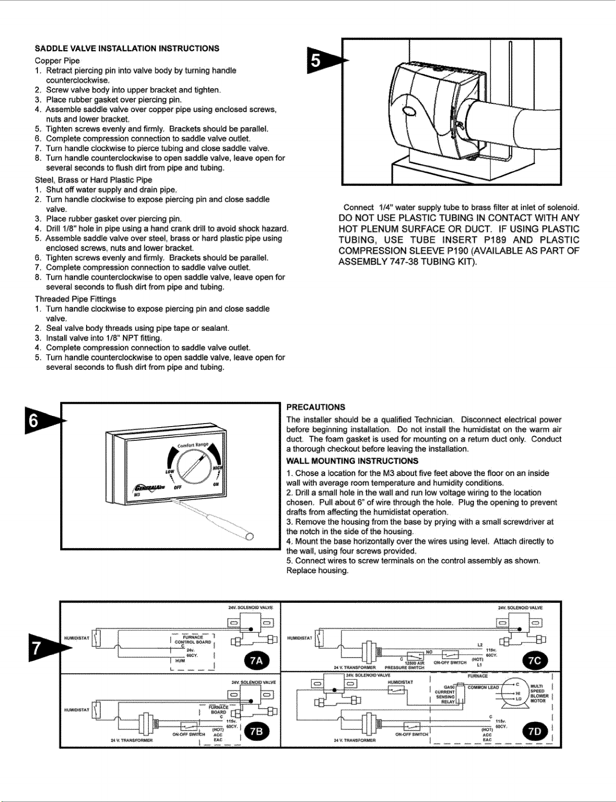
Conne_ _/4" water euppfytu_ tobraes flIter at inletof solenoid,
DO NOT USE PLASTIC TUBING _NCONTACT WITH ANY
HOT PLENUM SURFACE OR DUCT. IF USING PLASTIC
TUBING, USE TUBE INSERT Pt89 AND PLASTIC
COMPRESSION SLEEVE P190 (AVAILABLE AS PART OF
,ASSEMBLY 747-38 TUBING KIT),
PRECAUTIONS
The installer should be a qualified Technidan. Disconne_ electrical power
before beginning installatJono Do not instait the humidistat on the warm ,air
duct. The foam gasket is used for mounting on a return duct only. Conduct
a thorough checkout befo_ leaving the installation.
WALL MOUNTING INSTRUCTIONS
1_Chose a tocation fo_ the M3 about five feet above the _oor on an inside
wa_lwith average room tem_rature and humidi_ _nd_ions.
2_ Ddil a smail hole in the walt and run iow voltage widng to the |ocation
chosen_ Pul! about 6" of wire through the hole. Plug the opening to prevent
drat_s from affecting the humidistat operation_
3 Remove the housing from the base by p_ing with a smatl screwdriver at
the notch in the side of the housing,
4 Mount the ba_ horizontally over the wires using teveL Attach directiy to
the watt, using four screws provided.
5oConnect wires to screw te_inais on the control assemb|y as shown,
Replace housing.
Loading ...
Loading ...
Loading ...