Loading ...
Loading ...
Loading ...
4, Carefullypivotthesnowthrowerupandforwardsothatitrestson
theaugerhousing.
5. Removetheframecoverfromtheundersideofthesnowthrower
byremovingfourself-tappingscrewswhichsecureit.Referto
Figure24,
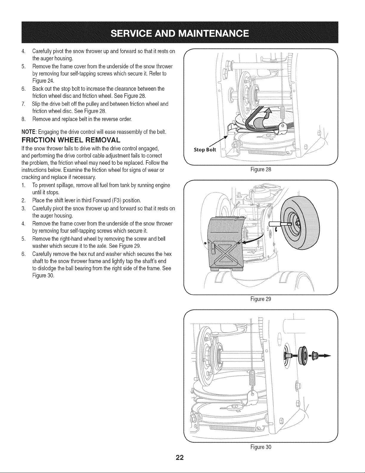
6. Backoutthestopbolttoincreasetheclearancebetweenthe
frictionwheeldiscandfrictionwheel,SeeFigure28,
7. Slipthedrivebeltoffthepulleyandbetweenfrictionwheeland
frictionwheeldisc,SeeFigure28,
8, Removeandreplacebeltinthereverseorder,
NOTE:Engagingthedrivecontrolwilleasereassemblyofthebelt.
FRICTION WHEEL REMOVAL
Ifthe snowthrowerfailsto drive with thedrivecontrol engaged,
andperformingthe drivecontrolcableadjustmentfails to correct
the problem,the frictionwheelmayneedto be replaced.Followthe
instructionsbelow.Examinethe frictionwheelfor signsof wearor
crackingandreplaceif necessary.
1. Topreventspillage,removeall fuel fromtank by runningengine
until it stops.
2. Placethe shiftleverin third Forward(F3) position.
3. Carefullypivotthe snowthrowerupand forwardso that it restson
theaugerhousing.
4. Removethe framecoverfromthe undersideof the snowthrower
by removingfourself-tappingscrewswhichsecureit.
5. Removethe right-handwheelby removingthe screwandbell
washerwhichsecureit to theaxle.See Figure29.
6. Carefullyremovethe hexnut and washerwhichsecuresthe hex
shaftto the snowthrowerframeand lightlytap the shaft'send
to dislodgethe ball bearingfrom the rightsideof theframe.See
Figure30.
Stop Bolt
Figure28
/ ii
J
Figure29
Figure30
J
22
Loading ...
Loading ...
Loading ...