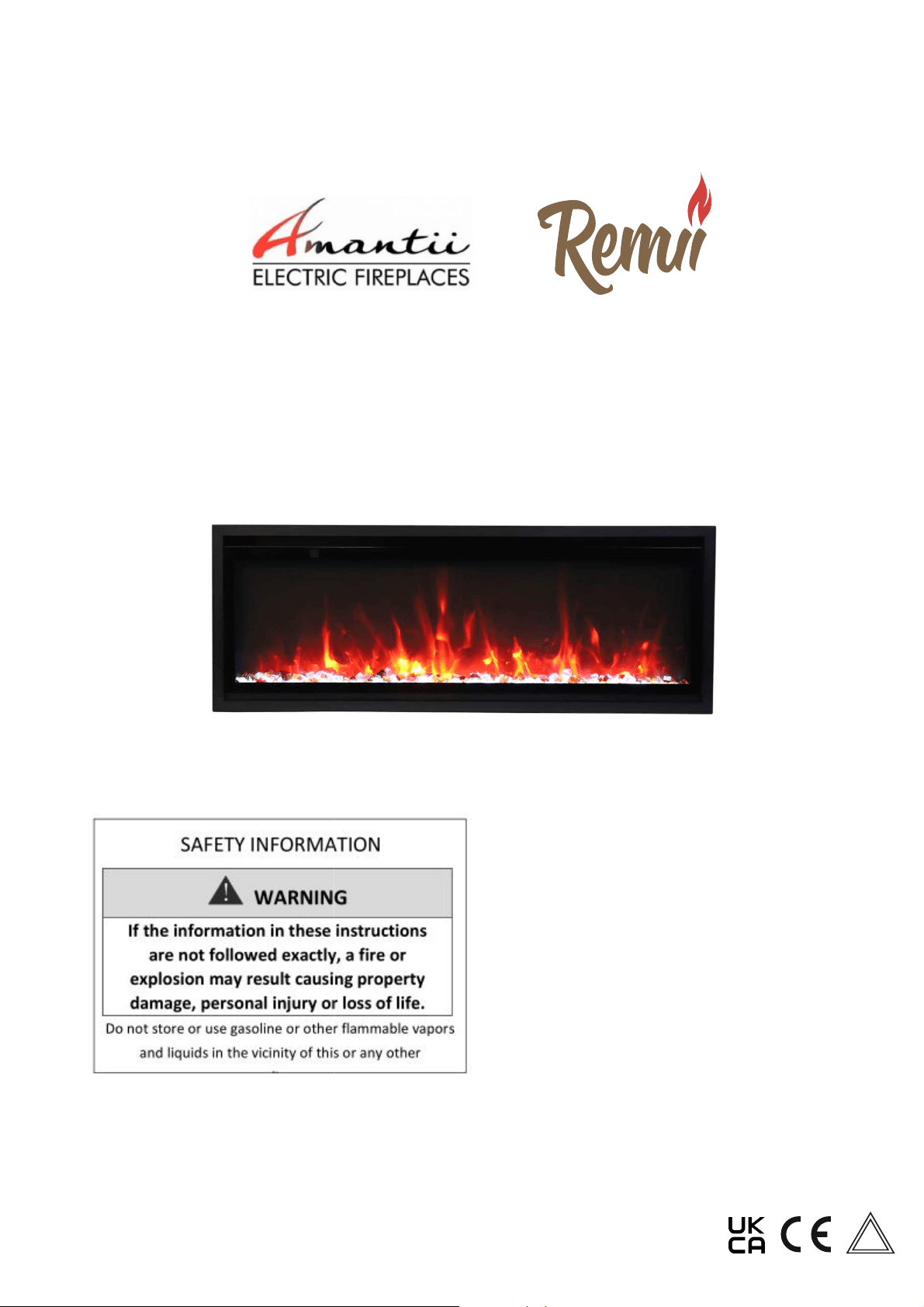
SYM-SLIM-42/WM-SLIM-45
-
(SM-X190042-1/EU2 / SM-X190045-1/EU2)
INSTALLATION /OWNER’S MANUAL
INSTALLER: LEA
CONSUMER: RETAIN
1
: LEAVE THIS MANUAL WITH THE APP
TAIN THIS MANUAL FOR FUTURE REFE
E APPLIANCE.
REFERENCE.
Version:202201
S
AA

2
TABLE OF CONTENTS
Please read and carefully follow all of the instruction found in this manual. The instructions
included here will assure that you have many years of dependable and enjoyable service
from your Amantii Electric Fireplace.
IMPORTANT INSTRUCTIONS
.........................................................................................................................................
3
PLUG INSTALLATION
......................................................................................................................................................
4
UNPACKING AND TESTING THE APPLIANCE
..........................................................................................................
5
CHOOSING FIREPLACE LOCATION
.............................................................................................................................
5
MANTEL CLEARANCE
.....................................................................................................................................................
5
SYM-SLIM-42/WM-SLIM-45(SM-X190042-1/EU2 / SM-X190045-1/EU2)
................................................................
6
WALL MOUNT INSTALLATION
...................................................................................................................................
..7
BUILT IN INSTALLATION
.............................................................................................................................................
..8
MEDIA OPTIONS
..............................................................................................................................................................
11
DECORATIVE MEDIA INSTALLATION
......................................................................................................................
11
OPERATION
.......................................................................................................................................................................
12
MANUAL OPERATION
...................................................................................................................................................
12
REMOTE CONTROL OPERATION
................................................................................................................................
13
WIFI OPERATION
............................................................................................................................................................. 15
CARE AND MAINTENANCE
.........................................................................................................................................
18
REPLACEMENT PARTS
..................................................................................................................................................
19
EXPLODED VIEW
............................................................................................................................................................
20
TROUBLE SHOOTING
.....................................................................................................................................................
21
SERVICE HISTORY
..........................................................................................................................................................
22
WARRANTY
......................................................................................................................................................................
23

IMPORTANT INSTRUCTIONS
PLEASE RETAIN THIS USER GUIDE FOR FUTURE REFERENCE
When using electrical appliances, basic precautions should always be followed to reduce the
risk of fire, electric shock, and injury to persons, including the following:
1) Read all instructions before using this fireplace
2) The fireplace is hot when in use. To avoid burns, do not let bare skin touch hot surfaces.
Keep combustible material such as furniture, cushions, bedding, paper, clothes, curtains
at least 3 feet from the front of the unit
3) Extreme caution is necessary when any heater is used near children and whenever the
unit is left operating and unattended.
4) Do not operate a fireplace with a damaged cord or plug, or if the heater has
malfunctioned, the fireplace has drooped or damaged in any manner
5) Not all fireplaces are suitable for use in bathrooms or laundry facilities. Please consult
with individual product literature to confirm suitability
6) Do not run the cord under carpeting. Do not cover cord with throw rugs, runners or the
like. Arrange the cord away from traffic area and where it will not be tripped over
7) Do not modify this fireplace. Use it as described in the manual. Any other use not
recommended by the manufacture may cause fire, shock or injury to persons
8) Do not use this heater with programmer, timer, separate remote-control system or any
other device that switches the heater on automatically, since a fire risk exists if the heater
is covered or positioned incorrectly
9) Disconnect all power supply before cleaning, maintenance or relocation of the fireplace
10) Keep the heater clean. Do not allow any objects to enter any ventilation or exhaust
opening as this may cause electric shock, fire or damage to the heater
11) Do not immerse the cord, plug or any part of the appliance in water or any other liquid
12) In order to avoid a hazard due to inadvertent resetting of the thermal cut-out, this
appliance must not be supplied through an external switching device
3
CAUTION: Procedures and techniques, which, if not carefully followed, will result in damage to
the equipment.
WARNING: Procedures and techniques, which, if not carefully followed, will expose the user to
the risk of fire, serious injury, illness or death.
SAVE THESE INSTRUCTIONS

Your power cord will come separate from the unit, please locate it when unpacking your
fireplace. The plug contained inside the box is predetermined at the factory and according to
orders placed by authorized dealers.
Please following the instructions to correctly install the plug into your fireplace.
1. Included in the box will be a power cord similar to the one pictured below. See Picture 1.
2. Hold the male plug and insert it into the female receptacle. The receptacle is locate on
the left side if the fireplace.
3. Please make sure the plugs are firmly connected. See Picture 2 above.
PLUG INSTALLATION
Picture 1 Picture 2
UK plug
European plug
Swiss plug
Australian plug
10103060E
10103030E
10103109E
10103088E
Available are UK, European, Swiss & Australian plugs. Should you require any of these
options please contact your dealer for purchase. You will be required to give them the
correct part number as listed below.
4

5
UNPACKING AND TESTING THE APPLIANCE
Carefully remove the appliance from the box.
Prior to installing the appliance, test to make sure the appliance operates properly by
plugging the power supply cord into a conveniently located 240 Volt grounded outlet.
Test all aspects of its operation (manual switches, remote and heater) to make sure all
components operate correctly.
As
with
most
electronic
devices
℉
,
your
new
℃
electric
fireplace
has
been
designed
to
operate
at
temperatures between 5
(41 ) and 3
5
(95 ). During the cold winter months, allow the
fireplace to reach room temperature before turning it on.
NOTE: There may be traces of odor during the first few minutes of initial use. This is
harmless and normal and will never occur again.
CHOOSING FIREPLACE LOCATION
Plan where to locate and frame the fireplace. This will save time and money later when you
install the fireplace. Before installation consider the following:
1.
Where the fireplace is located must allow for wall and ceiling clearances.
2.
Consider a location where the fireplace screen will not be exposed to direct sunlight from
windows or doors.
3.
A 15 ampere, 240 Volt, 50 Hz branch circuit with proper ground must be available at the
location. Preferably a dedicated branch circuit should be provided to avoid circuit
breakers to trip of fuses to blow.
℃
℉
MANTEL CLEARANCE
The clearance to the mantel should be 1/2” minimum when a mantel is applied (Measurement
is taken from the trim).
1/2"
Floor
Fireplace
Mantel
Wall
Fireplace

6
Description
Built-in Appliance
NO HEATER 25W
MOTOR HEATER 19W
Appliance Width 42 1/4” or 107.16 cm
Appliance Height 15 3/8 ” or 39.1 cm
Appliance Depth 4 1/8” or 10.4 cm
Gross Weight 63.27 lbs or 28.7 kgs
Plug Location Left side
Cord Length 70 7/8” or 180 cm
Rough Wall Opening
Size
42 1/2”× 15 5/8“ or
107.95 cm× 39.688 cm
BTU
16
1
2
" [418.2mm]
44
1
8
" [1120mm]
15
3
8
" [391mm]
4
1
8
" [104mm]
4
5
8
" [119mm]
10
3
4
" [273.5mm]
40
1
8
" [1019mm]
42
1
4
" [1071.6mm]
Voltage
Watts 1900W Max
6500
220-240V AC 50-60Hz
SYM-SLIM-42/WM-SLIM-45(SM-X190042-1/EU2)

7
INSTALLATION-
WALL MO
L MOUNT
NOTE: Due to the many different materials used to build walls, it is highly recommended that you consult your
local builder before you install this appliance on a wall.
1. Select a location that is not prone to moisture and is located at least 0.91 m or 3 feet away from combustible
materials such as curtains or drapes, furniture, bedding, paper, etc.
2. Using a spirit level to select a position in which to mount the heater horizontally. See Figure 1.
3. Check the wall to ensure there is no wiring, pipe wires etc in the area to be drilled. Drill 8 or more holes
depending on the size of the unit purchased, (8mm diameter & 40mm depth) using a suitable size drill bit and
insert the wall plugs into the holes.
4. Remove the hanger from the fireplace by removing the screws. See Figure 2.
5. Screw the left and right side steel panel to the left and right side to cover the screws. See Figure 3.
Min. 5cm
2 in
Min. 5cm
2 in
Min. 5cm
2 in
FLOOR
Fig 1
Fig 2
Fig 3
Fig 4
Fig 5
Fig 6
6. Fasten the hanger to the wall (See Figure 4.). Hang the fireplace onto the hanger (See Figure 5.).
7. To prevent fireplace from moving, use the provided safety screw to fasten the fireplace to the wall. See Figure 6.
WARNING: Be sure that the bolts have been fixed firmly enough to
withstand the weight!

INSTALLATION- BUILT-
IN
NOTE: Due to the many different
you consult your local builder bef
Preparation
1. Select
a location that is not pro
from combustible materials su
2.
Mark the desired location on
place.
3.
Prepare a wall with a frame
least 1/4” (6mm) around the
compliance with local and na
P
rior to installing, test the applian
plugging the power supply cord i
The rough wall opening size of t
INSTALLATION
8
IN
fferent materials used to build walls, it is highly
er before you install t
his appliance on a wall.
not prone to moisture and is located at least 0.91
ials such as curtains, drapes, furniture, bedding,
on on the floor and store the appliance in a saf
framed opening to accommodate the size of
nd the edge of the appliance. Any new wirin
nd national codes and other applicable regulat
ppliance to make sure the appliance is fully op
plugging the power supply cord into a 240 Volt grou
nded outlet.
ze of the fireplace:
highly recommended that
wall.
st 0.91m or 3 feet away
ding, paper, etc.
a safe, dry and dus
t free
ze of your unit. Leave at
wiring must be done in
egulations.
ully operational by
Screw
Screw
1. Unscrew 1 screw on each left and right side and push the front glass panel upward a bit
to take it off. (The screws are only for protection during transportation.)
W(“)
SYM-SLIM-42/
42 1/2
D(“)
H(“)
4 3/8 15 5/8
(SM-X190042-1/EU2 /
WM-SLIM-45
SM-X190045-1/EU2)

9
2.
Unscrew the 2 screws located
3.
Put the fireplace into the wall
ocated on each side and take
off the inner
side
e wall op
ening and fix it to be the wall.
side steel panels.
inner side steel panels
screws
screws
Screw the appliance onto the wall.

10
4.
Screw back the inner side ste
5. Put
back the front glass pane
de steel panel.
panel after you finish the med
ia decoration.
Screw back the inner side panel
that you removed at STEP 2.

11
MEDIA OPTIONS
T
he only media that comes with
optional decorative media if they
s with this appliance
is ‘Clear glass
’. Consum
if they choose. See deale
r for more details.
Clear glass
onsumers may purchase
DECORATIVE MEDIA INSTALL
TALLATION
I
NSTALLING THE DECORA
Pour the fire glass media into t
media that you find most appe
installing the fire glass.
CORATIVE MEDIA
into the tray. Feel free to use any combinati
t appealing. Put back the trim and front gla
bination of the fire glass
nt glass after you finish
Screw
Screw
Unscrew 1 screw on each le
take it off.
ch left and right side
and push
the front glass
glass panel
upward a bit to

12
OPERATION
Plug the fireplace into a 15 Amp
MANUAL OPERATION
Amp wall socket.
The Fireplace operates by using either the touch panel located on the upper left hand corner
or by remote control.
1.
2.
Press to turn on and off the fireplace.
Press to adjust the flame brightness. There are 6 brightness levels(L6-L1) and
an off(OF) position. Each time the flame button is pressed, the brightness of the flame
decrease.
press the flame button for 10 seconds, the timing indicator light on and will rapidly
blinks, at this time, You can use the TuyaSmart APP to connect to the fireplace.
4. Press
to set the turn-off time, 30min-1h-2h-3h-4h-5h-6h-7h-8h-t0. The indicator light
the current timing. If the timing in off position, the second press will show 30. Multiple times
to set operating duration to OF, 30 min, 1h, 2h, 3h, 4h, 5h, 6h, 7h, 8h.
5. Press
or the first time to display the current setting temperature,press the button
again to clear the current temperature. If the heater in off position, the second press will
show 22℃(72℉).Multiple times to set ambient temperatures at 22℃( 72℉) , 23℃
(74℉) ,24℃( 76℉) , 25℃( 78℉) , 26℃( 80℉) , 27℃( 82℉) , 28℃( 84℉) ,15℃( 52℉) ,
16℃( 54℉) , 17℃( 56℉) ,18℃( 58℉) , 19℃( 60℉) , 20℃( 62℉) , 21℃( 64℉) .
Temperature unit convert functionZ When the heater is on, press and hold the“ ”
Button for 5 seconds, current temperature unit display will convert to another temperature
unit.
3. is void in this model.

13
REMOTE CONTROL OPERATION
For remote to function make sure the fireplace is plugged in and the remote has batteries.
Important: When operating the remote make sure you point the remote to the center of the
fireplace. Each time you press the button, the buzzer inside the unit will beep once. It takes
some time for the receiver to respond to the transmitter. Do not PRESS the buttons more
than once within two seconds for correct operation.
Set the current time of the remote control
Press the to activate the remote control and press to set the time and date.
When one of the “Sun” “Mon” “ Tue” “Wed” “Thu” “Fri” “Sat” is flashing, press or to
set the day of the week, press to confirm day of the week and then enter hour setting.
Press or to set the hour, press to confirm the hour and then enter minute
setting. Press or to set the minute and press to confirm the minute and
finish time setting.
Press this Power button to turn on and off the fireplace.
Press this Timer button to set the time to turn off the fireplace.
The available settings range from 30 minutes to 8 hours. As
shown in the following: 0:30 - 1:00 - 1:30 - 2:00 - 2:30 - 3:00 -
3:30 - 4:00 - 4:30 - 5:00 - 5:30 - 6:00 - 6:30 - 7:00 - 7:30 - 8:00.
Once you have set the timer, the icon will be displayed
on the LCD screen of the remote control. Press this button
again to cancel the timer setting and the icon disappears.
Each time the Heater Button is pressed, the power of the
heater will change. As shown the following: H1- H2-
AUTO(22℃)- OFF(no display)
H1 means the fireplace on Low Heat/950W
H2 means the fireplace on High Heat/1900W

14
This button is void in this model.
Press this button to adjust the speed of the flame. There are 3 options: High-
Medium- Low.
Press the Flame button to turn on and off the Flame. When in ON position, the LCD
screen of the remote control shows 6 6 6. Press or or to change
the brightness of each color flame.
7 Day Timer Function
Press once, 7 days from Monday to Sunday will display on the LCD screen of
the remote control, press within 5 seconds to enter 7 day timer function. When
“Sun” flashes, press or to select the day that you want to set, press to
confirm your setting. Then “ON” will be display on the LCD screen of the remote
control, at the same time, digital of time hour flashes, press or to set the
time to turn the fireplace on. After setting the startup time, “OFF” will be displayed on
the LCD screen and press or to set the shutdown time. When the
shutdown time’s set, “AUTO” will be displayed on the LCD screen of the remote
control and the digital of temperature flashes. At this time, you can set the
temperature by or
. Now, you have finished setting of this function.
AUTO means fireplace can automatically adjust to the temperature you set. When in
AUTO, you can set the desired temperature with or keys. You can switch
temperature between Celsius and Fahrenheit with or keys.When it is on Auto
When the 7 day timer’s set, the icon will be displayed on the LCD screen of the
remote control. Press again to cancel the 7 da
will disappears.
NOTE: If the 7 day timing and the general timing are set at the same time, the
system will respond to an earlier shutdown time.
Press Refer button to check the settings of 7 day timer. Press or to see the
settings of the day of the week and or the settings of the startup and
shutdown time.
y timer and the icon
mode, fireplace operate at 1900W.

WIFI OPERATION
INSTALL TuyaSmart life
There are 2 ways to install TuyaSmart;
1. Search for “TuyaSmart life” in the APP store on your phone, download and install.
2. Scan the QR code below with your mobile phone.
WIFI SETTING AND FIREPLACE OPERATION
1. Create an account and log in.
2. When you log in, touch “+” (FIG.1) to enter in FIG.2. Touch “others” on the left corner first
and then choose “Connector (Wi-fi)” to enter in FIG.3 to set your Wi-fi account and
password.
FIG.1 FIG. 2 FIG.3
15

FIG.4
3. Press (flame button) on the touch panel of the fireplace for more than 5 seconds
when the fireplace in standby mode. There will be 2 beeps come out from the fireplace
and the (flame button) will flash as well indicating that Wi-fi is in EZ mode. Then
please confirm to go next. (FIG.5)
4. The APP will scan (FIG.6) and add the fireplace to APP (FIG.7) automatically. Please
make sure the Wi-fi account and password you set are correct and Wi-fi signal is good.
5. Touch “Done” to finish Wi-fi setting.(FIG.7)
FIG.5 FIG.6 FIG.7
16

6. Now you are in the interface like FIG.7. You can operate the fireplace via Wi-fi.
FIG.7
17
NOTE: Turn off the flashing blue Wifi indicator light
Touch the (power button) once, the blue light will stop flashing.

18
CARE AND MAINTENANCE
CAUTION: Do not use harsh detergents, chemical cleaners or solvents as they may damage the
surface finish of the plastic components.
CONFORMITY WITH DIRECTIVES
Conforms to all relevant European directives
ENVIRONMENTAL PROTECTION
Recycling
This symbol is known as the 'Crossed-out Wheelie Bin Symbol'. When
this symbol is marked on a product or battery, it means that it should not
be disposed of with your general household waste. Some chemicals
contained within electrical/electronic products or batteries can be harmful
to health and the environment.
Only dispose of electrical/electronic/battery items in separate collection
schemes, which cater for the recovery and recycling of materials contained
within. Your co-operation is vital to ensure the success of these schemes
and for the protection of the environment.
1. Switch off and unplug from the power supply before cleaning.
2. Using a soft, moist cloth, with or without a mild soap solution, carefully clean the exterior surface
of the products.
CAUTION: Allow the product to completely cool before handling or cleaning it.
3. Do not allow water or other liquids to run into the interior of the product, as this could create a
fire and/or electrical hazard.
4. We also recommend the periodic cleaning of this appliance by lightly running a vacuum cleaner
nozzle over the guards to remove any dust or dirt that may have accumulated inside or on the
unit.

19
REPLACEMENT PARTS
NO DESCRIPTION QTY
PART NUMBER
SYM-SLIM-42/WM-SLIM-45
(SM-X190042-1EU2 / SM-X190045-1/EU2)
1 TRIM 1 3236503
2 FRONT GLASS ASSEMBLY 1 3236507
3 TRAY GLASS 1 107022362
4 BACK GLASS 1 107022361
5 LED STRIP LIGHT FOR FLAME 3 601144
6 FLAME MOTOR 1 10101501
7 FLICKER ASSEMBLY 1 3236505
8 CIRCUIT BOARD 1 10124129
9
METAL SIDE PANEL
(RIGHT SIDE)
1 3236010
10 TEMPERATURE SENSOR 1 10114001B
11 TOUCH PANEL 1 10124003
12 BLOWER AND HEATER ASSEMBLY 1 602131C
13 HANGER 1 3236007
14
METAL SIDE PANEL
(LEFT SIDE)
1 3236009
15 SIGNAL RECEIVER 1 3001506B
16 TRAY LIGHT 1 10125023
17 WIFI CARD 1 212051
18 REMOTE CONTROL 1 10105501
*Remote control and tray light are not shown at the exploded view
*Items may not appear exactly as illustrated

20
EXPLODED VIEW

TROUBLE SHOOTING
PROBLEM POSSIBLE CAUSE SOLUTION
Dim or no flame Flame LED’s are burnt out Inspect the LED’s and replace
them if necessary
Back black cloth is falling off
and roll the flicker
Change a new flicker and back
black cloth
Ember bed is not
glowing or dimming
Ember LED’s are burnt out Inspect the ember bed LED’s and
replace them if necessary
Appliance turns off
and will not turn on
Appliance has overheated
and safety device has caused
the thermal switch to
disconnect
Turn off the main switch, allow
appliance to cool for 10 minutes,
then turn it on
House circuit breaker has
tripped
Reset house circuit breaker
Appliance’s fuse has blown Replace the fuse
Appliance will not
come on when switch
is flipped to ON
Appliance is not plugged into
an electrical outlet
Check plug and plug in
Appliance has overheated
and safety device has caused
the thermal switch to
disconnect
Turn off the main switch, allow
appliance to cool for 10 minutes,
then turn on
Circuit board is burnt out Inspect the circuit board and
replace if necessary
No warm air coming
out of appliance
Heater is burnt out Inspect the burner and heater
assembly and replace if necessary
Flame sputters
Flame motor is defective Call a qualified service technician
and replace flame motor
Remote Control does
not work
Low batteries
Unit switch in “O” position
Replace AAA batteries in remote
control
Turn the switch in “I” position
Flame is fixed Wiring may be loose or the
flame motor may be defective
21

SERVICE HISTORY
This heater must be serviced annually depending on usage.
Date Dealer
Name
Service Technician
Name
Service Performed
Special Concerns
NOTES:
22

23
