Loading ...
Loading ...
Loading ...
- 40 - - 41 -
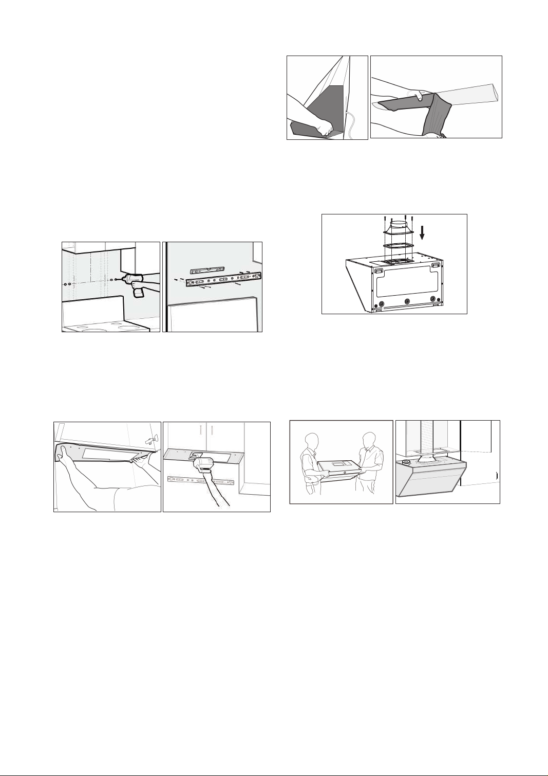
4.Fixing hooks:
1) Punch marks are on tiles (marble): Punch
holes (φ3/8"(φ8mm)) with an electric drill at
the marks, and embed expansion tube for
tiles(φ1/4"×1 5/16"(φ5.3×32mm)); x hook with
hook screws(#8×1 7/16"(ST4.2×36mm)), and
keep the hook level with a level ruler.
2) Punch marks are on plasterboards: Screw
the expansion tube for plasterboards(φ3/16"×1
5/8"(φ4×40mm)) into walls with screwdrivers
at the marks; x hooks with hook screws(#8×1
7/16"(ST4.2×36mm)), and keep the hook
horizontal with a level ruler.
5.
Place the hole-drilling template with the side
of the hole-drilling dimension drawing facing
down on the bottom of the upper cabinet, and
then drill the holes as indicated on the hole-
drilling template.
Caution:
Wear safety goggles when drilling.
In case of batten at the wall facing the bottom
plate, the rear wall side of the paper template
shall be cut as per the thickness of the batten.
If it is necessary to x the hook on the tile, the
“Rear Wall” side of the hole-drilling template
should be attached to the bottom of the upper
cabinet, using the tile surface as a reference.
6. Remove the protective film of the stainless
steel surface and Grease Cup at both sides of
the range hood.
7. Place the seal (notch downward) at the
air outlet of the machine and fix the outlet
housing with 4 outlet-housing bolts of
#8×3/4"(M4×18mm).
8. Lift and position the hood onto the brackets at
the top of the backside while keeping an angle
between the wall and the hood, and then push
the hood against the wall tightly. Secure the
duct to the duct cover and seal the connection
with aluminum tape.
Caution:
Two installers are required to ensure
safe installation.
9. Install the decorative plate.
Fix the decorative panel in place with 4 #6 × 1
7/16" (ST3.5×35mm) wood screws and fix the
decorative panel on the upper cabinet plate (the
wood screws are provided in the accessory bag
in the packing box of the decorative panel).
10. Make sure the hood is leveled. Install the
Grease Cup, and plug the appliance for a test run.
Warning:
Please wear the qualified protective
gloves in operation.
Caution:
Please run the machine and test if
the smoke pipe leaks air after it is sealed with
aluminum foil tape. The smoke pipe should be
able to be straightened as much as possible.
Installation Instructions for the Decorative
Cover Without Upper Cabinet
Diameter of smoke
tube Φ6" (152.5mm)
Diameter of hole digging
Φ
6 1/2" (165mm)
1. Unpack the appliance and check the List of
Accessories.
2. Locate the wooden beam and mark the
location with a pencil.
Framing Stud
3. Locate the duct bracket, safety buffer bafe
and decorative cover bracket:
safety stop
mounting hole
2
5
/1
6
"(
5
8
.5
m
m
)
4
9
/1
6
"(
11
5
.5
m
m
)
Max 29 15/16"(760mm)
Max 30 7/8"(783mm)
Min 27 7/8"(708mm)
4
9/16"(115.5mm)
Hole A
Area C
Hole B
Hole A
Area C
Hole B
Caution:
one of the wood screws(#10×2
9/16"(ST5×65mm)) for main engine must be
fastened to the beam.Screws must be fixed
Loading ...
Loading ...
Loading ...