
Loading ...
Loading ...
Loading ...
ENGLISH
10
Attaching and Removing Surface
Finishing Pads
DWE43214NVS Only
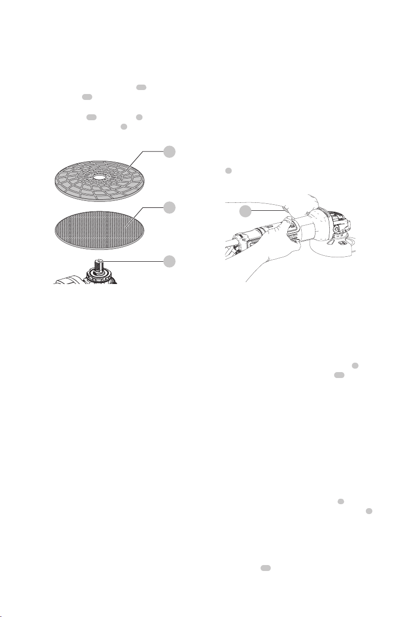
To attach surface finishing pad with hook and loop
backing pad (Fig. A, G)
1. Attach hook and loop accessory pad
23
to hook and
loop backing pad
22
, being careful to center the
backing pad with the accessory pad.
2. Screw backing pad
22
onto spindle
1
, while
depressing spindle lock button
2
.
23
22
1
Fig. G
To remove backing pads
Turn the backing pad by hand in the opposite direction
from normal rotation to allow lock button to engage
spindle, then unscrew pads in normal direction for right-
hand thread.
Prior to Operation
• Install the guard and appropriate disc or wheel. Do not
use excessively worn discs orwheels.
• Be sure the backing and threaded locking flange are
mounted correctly. Follow the instructions given in the
AccessoryChart.
• Make sure the disc or wheel rotates in the direction of
the arrows on the accessory and thetool.
• Do not use a damaged accessory. Before each use
inspect the accessory such as abrasive wheels for chips
and cracks, backing pad for cracks, tear or excess wear,
wire brush for loose or cracked wires. If power tool or
accessory is dropped, inspect for damage or install an
undamaged accessory. After inspecting and installing
an accessory, position yourself and bystanders away
from the plane of the rotating accessory and run the
power tool at maximum no-load speed for one minute.
Damaged accessories will normally break apart during
this testtime.
OPERATION
WARNING: To reduce the risk of serious personal
injury, turn unit off and disconnect it from
power source before making any adjustments or
removing/installing attachments or accessories.
An accidental start-up can causeinjury.
Proper Hand Position (Fig. H)
WARNING: To reduce the risk of serious personal injury,
ALWAYS use proper hand position asshown.
WARNING: To reduce the risk of serious personal
injury, ALWAYS hold securely in anticipation of a
suddenreaction.
Proper hand position requires one hand on the side
handle
5
, with the other hand on the body of the tool, as
shown in FigureH.
Fig. H
5
Paddle Switch (Fig. A)
CAUTION: Hold the side handle and body of the tool
firmly to maintain control of the tool at start up and
during use and until the wheel or accessory stops
rotating. Make sure the wheel has come to a complete
stop be fore laying the tooldown.
CAUTION: Before connecting the tool to a power
source depress and release the paddle switch
8
once
without depressing the lock-on button
10
to ensure
that the switch is off. Depress and release the paddle
switch as described above after any interruption in
power supply to the tool, such as the activation of a
ground fault interrupter, throwing of a circuit breaker,
accidental unplugging, or power failure. If the paddle
switch is locked on, the tool will start unexpectedly
when it isreconnected.
NOTE: To reduce unexpected tool movement, do not
switch the tool on or off while under load conditions. Allow
the grinder to run up to full speed before touching the work
surface. Lift the tool from the surface before turning the tool
off. Allow the tool to stop rotating before putting itdown.
1. To turn the tool on, push the lock-off lever
9
toward
the back of the tool, then depress the paddle switch
8
.
The tool will run while the switch isdepressed.
2. Turn the tool off by releasing the paddleswitch.
Lock-On Button
DWE43214
The lock-on button
10
offers increased comfort in
extended use applications. To lock the tool on, depress
the lock-on button while the tool is running. The tool will
Loading ...
Loading ...
Loading ...