Loading ...
Loading ...
Loading ...
ENGLISH
8
(spindle facing user) but self-locks in the counter-
clockwisedirection.
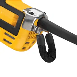
• Two-touch
TM
: In this position the engaging face is
straight and squared off. It will NOT ride over to the next
alignment hole unless guard release lever is pressed and
held while simultaneously rotating the guard in either
a clockwise or counter-clockwise direction (spindle
facinguser).
One-Touch
TM
Two-Touch
TM
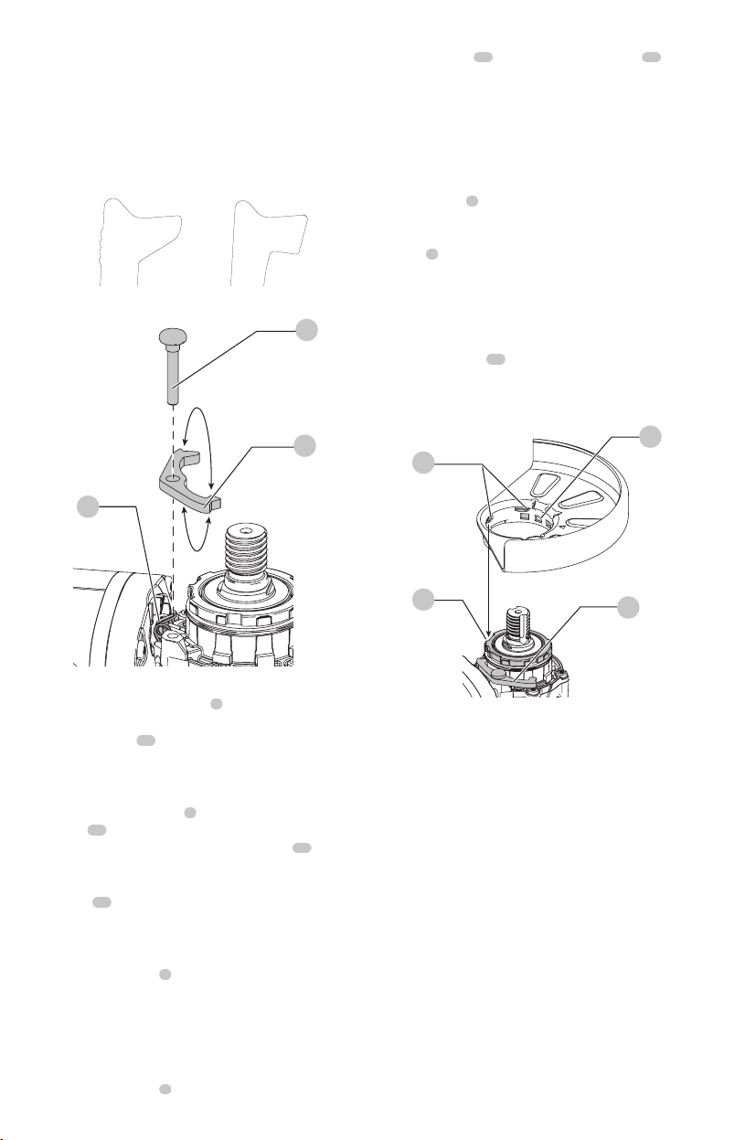
Fig. C
7
18
26
Setting Guard Adjustment Options
To adjust the guard release lever
7
for desired
adjustmentoption:
1. Remove screw
18
using a T20bit.
2. Remove the guard release lever taking note of the
spring position. Choose the end of the lever for the
desired adjustment option. One-touch will use the
slanted end of the lever
7
to engage the alignment
holes
14
on the guard collar. Two-touch will use the
squaredend to engage the alignment holes
14
on the
guardcollar.
3. Replace the lever, positioning the chosen end under the
spring
26
. Ensure the lever is in proper contact with
thespring.
4. Replace screw and torque to 2.0-3.0N-m. Ensure proper
installation with spring return function by depressing
guard release lever
7
.
Mounting Guard (Fig. D)
CAUTION: Prior to mounting guard, ensure the screw,
lever, and spring are fitted correctly before mounting
theguard.
1. With the spindle facing the operator, press and hold the
guard release lever
7
.
2. Align the lugs
15
on the guard with the slots
16
on
the gearcasecover.
3. Push the guard down until the guard lugs engage
and rotate them in the groove on the gear case cover.
Release the guard releaselever.
4. To position the guard:
One-touch
TM
: Rotate the guard clockwise into the
desired working position. Press and hold the guard
release lever
7
to rotate the guard in the counter-
clockwisedirection.
Two-touch
TM
: Press and hold the guard release
lever
7
. Rotate the guard clockwise or counter-
clockwise into the desired workingposition.
NOTE: The guard body should be positioned between
the spindle and the operator to provide maximum
operatorprotection.
The guard release lever should snap into one of the
alignment holes
14
on the guard collar. This ensures
that the guard issecure.
5. To remove the guard, follow steps 1–3 of these
instructions inreverse.
Fig. D
14
16
15
7
Flanges and Wheels
CAUTION: Turn unit off and unplug the tool before
making any adjustments or removing or installing
attachments oraccessories.
Mounting Non-Hubbed Wheels (Fig. E)
WARNING: Failure to properly seat the flanges and/or
wheel could result in serious injury (or damage to the
tool or wheel).
CAUTION: Included flanges must be used with
depressed center Type 27/42 grinding wheels and
Type1/41 cutting wheels. Refer to the Accessories
Chart for moreinformation.
WARNING: A closed, two-sided cutting wheel guard
is required when using abrasive cutting wheels or
diamond coated cuttingwheels.
WARNING: Use of a damaged flange or guard or fail-
ure to use proper flange and guard can re sult in injury
due to wheel breakage and wheel contact. Refer to
the Accessories Chart for moreinformation.
1. Place the tool on a table, guardup.
Loading ...
Loading ...
Loading ...