OPERATION AND INSTALLATION
Electronically controlled comfort instantaneous water heater
» DEL13PlusAU
» DEL18PlusAU
» DEL27PlusAU
Tmax
T

2 | DEL Plus AU www.stiebel-eltron.com
CONTENTS
SPECIAL INFORMATION
OPERATION
1. General information �����������������������������������������3
1.1 Safety instructions ����������������������������������������������� 3
1.2 Other symbols in this documentation ����������������������� 4
1.3 Units of measurement ������������������������������������������ 4
2. Safety ���������������������������������������������������������� 4
2.1 Intended use ������������������������������������������������������ 4
2.2 General safety instructions ������������������������������������ 4
2.3 Test symbols ������������������������������������������������������ 4
3. Appliance description ���������������������������������������4
4. Settings and displays ����������������������������������������5
4.1 User interface ���������������������������������������������������� 5
4.2 Display symbols �������������������������������������������������� 5
4.3 Selecting the set temperature ��������������������������������� 5
4.4 Temperature limit via internal anti-scalding
protection (qualified contractor)������������������������������ 5
4.5 Temperature limit Tmax (user) �������������������������������� 6
4.6 Allocating temperature memory buttons ������������������� 6
4.7 Settings menu ���������������������������������������������������� 6
4.8 Selecting ECO level ���������������������������������������������� 6
4.9 Inlet temperature information �������������������������������� 6
4.10 Recommended settings ���������������������������������������� 6
5. Cleaning, care and maintenance ���������������������������7
6. Troubleshooting ����������������������������������������������7
INSTALLATION
7. Safety ���������������������������������������������������������� 7
7.1 General safety instructions ������������������������������������ 7
7.2 Instructions, standards and regulations �������������������� 7
8. Appliance description ���������������������������������������8
8.1 Standard delivery ������������������������������������������������ 8
8.2 Accessories �������������������������������������������������������� 8
9. Preparation ���������������������������������������������������8
9.1 Installation location ��������������������������������������������� 8
9.2 Minimum clearances �������������������������������������������� 8
9.3 Water installation ������������������������������������������������ 9
10. Installation ����������������������������������������������������9
10.1 Standard installation �������������������������������������������� 9
11. Commissioning ��������������������������������������������� 11
11.1 Preparation ������������������������������������������������������ 11
11.2 Initial start-up ��������������������������������������������������� 11
11.3 Recommissioning ����������������������������������������������� 12
12. Appliance shutdown ��������������������������������������� 12
13. Alternative installation methods ������������������������� 12
13.1 Electrical connection from above on unfinished walls �� 12
13.2 Electrical connection on unfinished walls with short
power cable ������������������������������������������������������ 13
13.3 Electrical connection on finished walls ��������������������13
13.4 Water installation on unfinished walls ��������������������� 13
13.5 Wall mounting bracket when replacing an appliance ��� 14
13.6 Installation with offset tiles ����������������������������������� 14
13.7 Pivoting appliance cover �������������������������������������� 14
13.8 Operation with preheated water ���������������������������� 15
13.9 Horizontal installation of the appliance �������������������� 15
14. Service information ���������������������������������������� 15
15. Troubleshooting �������������������������������������������� 16
15.1 Fault code display ���������������������������������������������� 16
16. Maintenance ������������������������������������������������ 17
17. Specification ������������������������������������������������ 17
17.1 Dimensions and connections ��������������������������������� 17
17.2 Wiring diagram ������������������������������������������������� 18
17.3 DHW output ������������������������������������������������������ 18
17.4 Application areas/ Conversion table ����������������������� 18
17.5 Pressure drop ��������������������������������������������������� 18
17.6 Fault conditions ������������������������������������������������� 18
17.7 Data table �������������������������������������������������������� 19
ENVIRONMENT AND RECYCLING
WARRANTY

www.stiebel-eltron.com DEL Plus AU | 3
SPECIAL INFORMATION | OPERATION
General information
SPECIAL INFORMATION
- The appliance may be used by children aged3
and older and persons with reduced physical,
sensory or mental capabilities or a lack of ex-
perience and know-how, provided that they
are supervised or they have been instructed
on how to use the appliance safely and have
understood the potential risks. Children must
never play with the appliance. Children must
never clean the appliance or perform user
maintenance unless they are supervised.
- If using preheated water, the tap can reach a
temperature of up to 50°C during operation.
There is a risk of scalding at outlet tempera-
tures in excess of 43 °C.
- The appliance is suitable for supplying a
shower (shower operation). When using pre-
heated water, it must be ensured that the inlet
temperature does not exceed 50°C.
- Ensure the appliance can be separated from
the power supply by an isolator that discon-
nects all poles with at least 3mm contact
separation.
- The specified voltage must match the power
supply.
- The appliance must be connected to earth.
- The appliance must be permanently connect-
ed to fixed wiring.
- Secure the appliance as described in chapter
"Installation/ Installation".
- Observe the maximum permissible pressure
(see chapter "Installation/ Specification/ Data
table").
- The specific water resistivity of the mains
water supply must not be undershot (see
chapter "Installation/ Specification/ Data
table").
- Drain the appliance as described in chapter
"Installation/ Maintenance/ Draining the
appliance".
OPERATION
1. General information
The chapters "Special information" and "Operation" are intended
for both users and qualified contractors.
The chapter "Installation" is intended for qualified contractors.
Note
Read these instructions carefully before using the appli-
ance and retain them for future reference.
Pass on the instructions to a new user if required.
1.1 Safety instructions
1.1.1 Structure of safety instructions
!
KEYWORD Type of risk
Here, possible consequences are listed that may result
from failure to observe the safety instructions.
f Steps to prevent the risk are listed.
1.1.2 Symbols, type of risk
Symbol Type of risk
Injury
Electrocution
Burns
(burns, scalding)
1.1.3 Keywords
KEYWORD Meaning
DANGER Failure to observe this information will result in serious
injury or death.
WARNING Failure to observe this information may result in serious
injury or death.
CAUTION Failure to observe this information may result in non-seri-
ous or minor injury.
!

OPERATION
Safety
4 | DEL Plus AU www.stiebel-eltron.com
1.2 Other symbols in this documentation
Note
General information is identified by the adjacent symbol.
f Read these texts carefully.
Symbol Meaning
Material losses
(appliance damage, consequential losses and environmen-
tal pollution)
Appliance disposal
f This symbol indicates that you have to do something. The ac-
tion you need to take is described step by step.
1.3 Units of measurement
Note
All measurements are given in mm unless stated oth-
erwise.
2. Safety
2.1 Intended use
This appliance is suitable for heating domestic hot water or for
reheating preheated water. The appliance can supply one or more
draw-off points.
Water will not be reheated if the maximum inlet temperature for
reheating is exceeded.
The appliance is intended for domestic use. It can be used safely
by untrained persons. The appliance can also be used in non-do-
mestic environments, e.g.in small businesses, as long as it is
used in the same way.
Any other use beyond that described shall be deemed inappro-
priate. Observation of these instructions and of the instructions
for any accessories used is also part of the correct use of this
appliance.
2.2 General safety instructions
CAUTION Burns
If using preheated water, the tap can reach a temper-
ature of up to 50°C during operation. There is a risk of
scalding at outlet temperatures in excess of 43 °C.
CAUTION Burns
If children or persons with limited physical, sensory or
mental capabilities use the appliance, set a temperature
limit. Once set, check the temperature limit is working
correctly.
If a permanent and unchangeable temperature limit is
required, have the internal anti-scalding protection set
by a qualified contractor.
CAUTION Burns
If operating with preheated water, e.g. if using a solar
thermal system, observe the following information:
- The DHW temperature may exceed the set tempera-
ture or a set temperature limit.
- The dynamic anti-scalding protection between the
appliance and a wireless remote control may not be
effective.
f In such cases, limit the temperature with an up-
stream central thermostatic valve.
!
WARNING Injury
The appliance may be used by children aged3 and older
and persons with reduced physical, sensory or mental
capabilities or a lack of experience and know-how, pro-
vided that they are supervised or they have been in-
structed on how to use the appliance safely and have
understood the potential risks. Children must never play
with the appliance. Children must never clean the ap-
pliance or perform user maintenance unless they are
supervised.
!
WARNING
For continued safety of this appliance it must be in-
stalled, operated and maintained in accordance with
the manufacturer's instructions.
!
WARNING
This appliance must only be installed in accordance
with the acceptable plumbing configurations specified
in these instructions. Failure to do so may result in condi-
tions where delivery temperature control is inadequate.
!
Material losses
The user should protect the appliance and its tap against
frost.
2.3 Test symbols
See type plate on the appliance
3. Appliance description
The appliance switches on automatically as soon as you open the
hot water valve on the tap. When you close the tap, the appliance
switches off again automatically.
The appliance heats water as it flows through it. The set tempera-
ture is adjustable. Upwards of a certain flow rate, the control unit
selects the required heating output, subject to the temperature
selected and the cold water temperature.
The electronically controlled instantaneous water heater with au-
tomatic output matching maintains a consistent outlet tempera-
ture. It is irrespective of the inlet temperature, up to the maximum
output of the appliance.
If the appliance is operated with preheated water and the inlet
temperature exceeds the selected temperature, the word "hot"
and the inlet temperature are displayed alternately, and the "hot"
LED flashes. The water is not heated further.
!
OPERATION
Settings and displays
www.stiebel-eltron.com DEL Plus AU | 5
You can store different set temperatures and call them up quickly.
With the ECO function, the flow rate is limited to 3 preset levels.
The appliance has setting options for a temperature limit (Tmax
function, user) and internal anti-scalding protection (qualified
contractor). The backlight switches on automatically as soon as
water starts to flow through the appliance or you make a change
on the user interface. The backlight switches off automatically
after water stops flowing or if no action is performed.
Heating system
The bare wire heating system is enclosed within a pressure-tested
plastic jacket. The heating system with its stainless steel heater
spiral is suitable for hard and soft water areas and is largely in-
susceptible to scale build-up. The heating system ensures rapid
and efficient DHW provision.
Note
The appliance is equipped with an air detector that large-
ly prevents damage to the heating system. If, during op-
eration, air is drawn into the appliance, the appliance
shuts down for one minute, thereby protecting the heat-
ing system.
4. Settings and displays
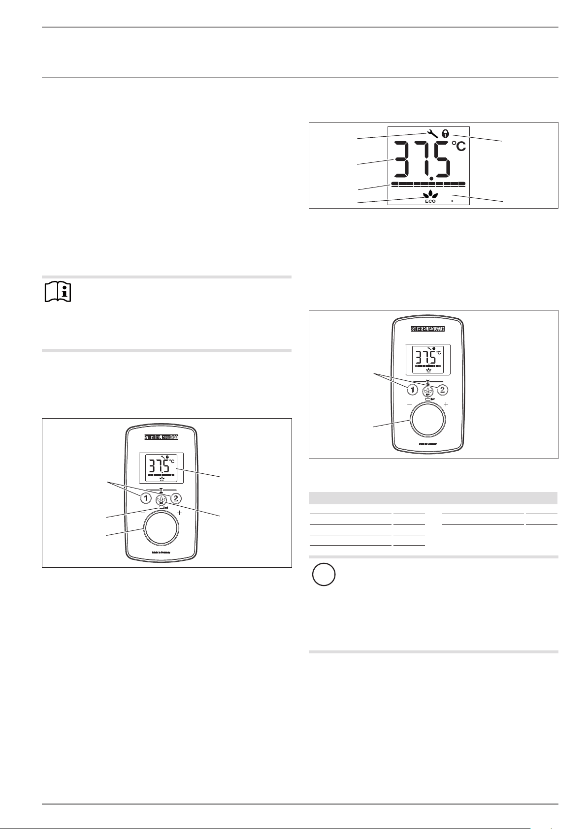
4.1 User interface
Tmax
T
D0000073010
2
3
1
5
4
1 Temperature selector
2 "hot" scald warning LED, at temperatures higher than 43°C
3 Temperature memory buttons 1 and 2
4 Display
5 ECO button with ECO level selection/ Menu call-up
4.2 Display symbols
Tmax
T
D0000073009
4
3
1
2
5
6
1 ECO indicator [rolling, levels 1 - 3, OFF]
2 Output bar [10 - 100%]
3 Segment display [°C/°F]
4 In the event of an appliance fault, a spanner appears
5 Operating lock [ON/OFF]
6 Tmax, displayed when temperature limit is enabled
4.3 Selecting the set temperature
Tmax
T
D0000073010
2
1
1 Set temperature settings: OFF, 20 - 50°C
2 Call up/assign preferred temperatures
Setting steps
Temperature range Step Temperature range Step
20°C ... 35°C 1°C 68°F ... 122°F 1°F
35°C ... 43 °C 0.5°C
43°C ... 50°C 1°C
!
Note
If the outlet temperature is not high enough when the
draw-off valve is fully open and the temperature selector
is set to maximum, then more water is flowing through
the appliance than can be heated by the heating system
(appliance working at maximum output).
f Use the ECO button to reduce the water volume until
the required temperature is achieved.
4.4 Temperature limit via internal anti-scalding
protection (qualified contractor)
If required, the qualified contractor can set a permanent temper-
ature limit, for example in nurseries, hospitals,etc.
If the anti-scalding protection function (43°C) is enabled, "Tmax"
flashes continually once the set temperature has been reached.

OPERATION
Settings and displays
6 | DEL Plus AU www.stiebel-eltron.com
4.5 Temperature limit Tmax (user)
The temperature limit allows you as a user to restrict the adjusta-
ble set temperature at the appliance to a maximum value.
Your qualified contractor can set an additional temperature limit
for anti-scalding protection. This temperature then dictates the
upper limit of the setting range for the temperature limit function.
4.5.1 Enabling the temperature limit
f Press and hold buttons "1" and "2" for longer than 5seconds,
until "Tmax" and the temperature display flash.
f Select a temperature limit.
10seconds after completing the setting, the menu item will dis-
appear automatically.
If the high limit safety cut-out is enabled, "Tmax" is continuously
displayed.
Check that the upper temperature limit has been correctly applied.
4.5.2 Disabling the temperature limit
f Disable the high limit safety cut-out by pressing and holding
buttons "1" and "2" for longer than 5seconds.
4.6 Allocating temperature memory buttons
Memory buttons "1" and "2" can each be assigned a required
temperature.
f Select the required temperature.
f To store the required temperature, press and hold button "1"
or "2" for longer than 3seconds. The selected temperature
flashes once to confirm.
4.7 Settings menu
Menu Description
Temperature display Select °C or °F
Operating lock Select ON or OFF. Symbol displayed
Fault code display Displays E1...E3 if there is a fault on the appli-
ance. Call qualified contractor.
f To call up the menu, press and hold the ECO button for
longer than 5seconds.
f To select, turn the temperature selector.
f Press the ECO button once more.
f To quit the menu, press and hold the ECO button for longer
than 5seconds.
The menu switches off automatically if no operation has been
performed for 30seconds.
Note
To call up the menu when the operating lock is enabled,
press and hold the ECO button for longer than 10seconds.
4.8 Selecting ECO level
ECO level Display Flow rate limitation
Level 1 8l/min (factory setting)
Level 2 7l/min
Level 3 6l/min
OFF No symbol No flow rate limit
f Briefly press the ECO button. Rolling selection, "Level1 - 3/
OFF".
4.9 Inlet temperature information
If the appliance is operated with preheated water and the inlet
temperature exceeds the selected temperature, the word "hot"
and the inlet temperature are displayed alternately, and the "hot"
LED flashes.
4.10 Recommended settings
Your instantaneous water heater offers maximum precision and
maximum convenience in DHW provision. Should you nonetheless
be operating the appliance with a thermostatic valve, we recom-
mend that you:
f Set the temperature at the instantaneous water heater to the
maximum temperature. Then set the required set tempera-
ture on the thermostatic valve.
Saving energy
The following recommended settings will result in the lowest en-
ergy consumption:
- 38°C for hand washbasins, showers, bath
- 50°C for kitchen sinks
Internal anti-scalding protection (qualified contractors)
If required, the qualified contractor can set a permanent temper-
ature limit, for example in nurseries, hospitals,etc.
Limiting it in this way prevents water from flowing out of the
appliance at temperatures which could cause injury.
Recommended setting for operation with a thermostatic valve
and water preheated by solar energy
f Set the temperature at the instantaneous water heater to the
maximum temperature.
Following an interruption to the water supply
!
Material losses
To ensure that the bare wire heating system is not dam-
aged following an interruption to the water supply, the
appliance must be restarted by taking the following steps.
f Disconnect the appliance from the power supply by
removing the fuses/tripping the MCBs.
f Open the tap for one minute until the appliance and
its upstream cold water inlet line are free of air.
f Switch the power back ON.
www.stiebel-eltron.com DEL Plus AU | 7
OPERATION | INSTALLATION
Cleaning, care and maintenance
5. Cleaning, care and maintenance
f Never use abrasive or corrosive cleaning agents. A damp
cloth is sufficient for cleaning the appliance.
f Check the taps regularly. Limescale deposits at the tap out-
lets can be removed using commercially available descaling
agents.
6. Troubleshooting
Problem Cause Remedy
The appliance will not
start despite the DHW
valve being fully open.
There is no power.
Check the fuses/MCBs in
your fuse box/distribu-
tion board.
The aerator in the tap or
the shower head is scaled
up or dirty.
Clean and/or descale the
aerator or shower head.
The water supply has
been interrupted.
Vent the appliance and
the cold water inlet line.
When hot water is being
drawn off, cold water
flows for a short period.
The air detector de-
tects air in the water. It
switches off the heating
output briefly.
The appliance restarts
automatically after
1minute.
The required tempera-
ture cannot be set.
The high limit safety
cut-out and/or internal
anti-scalding protection
are enabled.
Deactivate the temper-
ature limit. The internal
anti-scalding protection
can only be adjusted by
the qualified contractor.
The flow rate is too low.
ECO function is enabled.
Select a different ECO
level or disable the ECO
function.
No settings can be made
on the programming
unit.
The operating lock is
enabled.
Press and hold the ECO
button for more than
10seconds to disable the
operating lock.
Note
Programming unit displays and selected settings are re-
tained following a power failure.
If you cannot remedy the fault, contact your qualified contractor.
To facilitate and speed up your request, provide the number from
the type plate (000000-0000-000000).
Nr. 000000-0000-00000
Nr. 000000-0000-00000
D0000053312
INSTALLATION
7. Safety
Only a qualified contractor should carry out installation, commis-
sioning, maintenance and repair of the appliance.
7.1 General safety instructions
We guarantee trouble-free function and operational reliability only
if original accessories and spare parts intended for the appliance
are used.
!
Material losses
Observe the maximum inlet temperature. Higher tem-
peratures may damage the appliance. You can limit the
maximum inlet temperature by installing a central ther-
mostatic valve.
CAUTION Burns
If operating with preheated water, e.g. if using a solar
thermal system, observe the following information:
- The DHW temperature may exceed the set tempera-
ture or a set temperature limit.
- The dynamic anti-scalding protection between the
appliance and a wireless remote control may not be
effective.
f In such cases, limit the temperature with an up-
stream central thermostatic valve.
WARNING Electrocution
This appliance contains capacitors which are discharged
when disconnected from the power supply. The capacitor
discharge voltage may briefly exceed60VDC.
7.2 Instructions, standards and regulations
Note
Observe all applicable national and regional regulations
and instructions.
Note
The installation of this appliance shall conform to the
Plumbing Code of Australia (PCA), and the New Zealand
Building Code.
Note
This appliance delivers water not exceeding 50°C in ac-
cordance with AS3498.
- The IP24/ IP25 protection rating can only be ensured with a
correctly fitted cable grommet.
- The specific electrical resistivity of the water must not fall
below that stated on the type plate. In a linked water net-
work, factor in the lowest electrical resistivity of the water.
Your water supply utility will advise you of the specific elec-
trical water resistivity or conductivity.

INSTALLATION
Appliance description
8 | DEL Plus AU www.stiebel-eltron.com
Test for delivery temperature performance
The appliance is to be tested according to AS3498 as a 50°C-
limited water heater. The option1 illustrated in figureA.1 of the
AppendixA applies to the appliance.
Inlet
Water
heater
P
i
T
i
F
1
Pipe 1
Valve 1
Valve 2
T
D
Outlet for delivery to
sanitary fixtures used
primarily for personal
hygiene purposes
(and any other fixtures)
D0000100267
Figure A.1 - Option1 - Simple water heater
Key
—•— Measurement location
Pipe 1 Pipework to sanitary fixtures used primarily for personal
hygiene purposes
F
1
Flow rate to sanitary fixtures used primarily for personal
hygiene purposes
P
i
Inlet pressure
T
i
Inlet temperature
T
D
Delivery temperature (represents water temperature at the
outlet from sanitary fixtures used primarily for personal
hygiene purposes)
Valves 1 and 2 Valves to control water flow for the purposes of testing
8. Appliance description
8.1 Standard delivery
The following are delivered with the appliance:
- Wall mounting bracket
- Installation template
- 2 plugs
- 2 extensions
- 2 caps
- 2 tees
- 8 flat gaskets
- Strainer
- Plastic profile washer
- Plastic connection pieces/installation aid
- Cover and back panel guides
- Jumper for internal anti-scalding protection
8.2 Accessories
Wireless remote control
- FFB4SetAP
9. Preparation
9.1 Installation location
!
Material losses
Install the appliance in a room free from the risk of frost.
f Always install the appliance vertically and near the draw-off
point. For horizontal installation, see chapter "Alternative in-
stallation methods/ Horizontal installation of the appliance".
The appliance is suitable for undersink and oversink installation.
Undersink installation
D0000056242
1
2
1 Cold water inlet
2 DHW outlet
Oversink installation
D0000057030
12
1 Cold water inlet
2 DHW outlet
Note
f Mount the appliance on the wall. The wall must have
sufficient load bearing capacity.
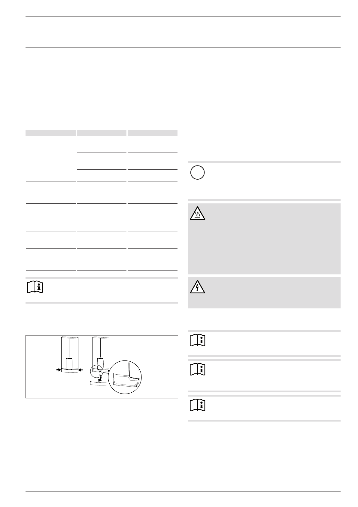
9.2 Minimum clearances
≥50≥50
≥90
≥90
D0000060809
f Maintain the minimum clearances to ensure trouble-free op-
eration of the appliance and facilitate maintenance work.

INSTALLATION
Installation
www.stiebel-eltron.com DEL Plus AU | 9
9.3 Water installation
f Flush the water line thoroughly.
Taps/valves
Use appropriate pressure taps. Open vented taps are not per-
missible.
Permissible water line materials
- Cold water inlet line:
Pipes made from galvanised steel, stainless steel, copper or
plastic
- DHW outlet line:
Stainless steel pipe, copper pipe or plastic pipe
!
Material losses
If plastic pipework systems are used, take into account
the maximum inlet temperature and the maximum per-
missible pressure.
Flow rate
f Ensure that the flow rate for switching on the appliance is
achieved.
f Increase the water line pressure if the required flow rate is
not achieved when the draw-off valve is fully open.
10. Installation
Factory settings DEL13Plus AU DEL 18 Plus AU DEL27Plus AU
Internal anti-scald-
ing protection
Tmax (= 50°C) Tmax (= 50°C) Tmax (= 50°C)
Standard instal-
lation
DEL13Plus AU DEL 18 Plus AU DEL27Plus AU
Electrical connec-
tion from below on
unfinished walls
x
x
x
Water connection,
installation on fin-
ished walls
x
x
x
For further installation options, see chapter "Alternative instal-
lation methods".
10.1 Standard installation
Opening the appliance
D0000053271
f Open the appliance by holding the fascia at the side and pull-
ing forwards away from the appliance cover. Undo the screw.
Pivot open the appliance cover.
D0000053272
f Remove the back panel by pressing the two locking tabs and
pulling the lower back panel section forwards.
Preparing the power cable on unfinished walls, for connection
from below
160
30
D0000053273
1
1 Cable entry installation aid
f Prepare the power cable.
Fitting the wall mounting bracket
D0000059694
f Mark out the holes for drilling using the installation tem-
plate. If the appliance is to be installed on finished walls, also
mark out the fixing hole in the lower section of the template.
f Drill the holes and secure the wall mounting bracket at 2
points using suitable fixing materials (screws and rawl plugs
are not part of the standard delivery).
f Fit the wall mounting bracket.

INSTALLATION
Installation
10 | DEL Plus AU www.stiebel-eltron.com
Preparing the water connection
!
Material losses
Carry out all water connection and installation work in
accordance with regulations.
24
5 Nm
24
5 Nm
19
5 Nm
19
5 Nm
D0000041720
f Remove the caps from the tees.
f Fit the plugs and the extensions with gaskets.
D0000041721
f Fit the strainer in the tee for the cold water inlet.
!
Material losses
The strainer must be fitted for the appliance to function.
f When replacing an appliance, check whether the
strainer is installed.
Installing the appliance
Note
If you are installing the appliance with flexible pipe con-
nections, also secure the bottom of the back panel with
a screw.
D0000077728
1
2
1 Cable entry installation aid
2 Cable grommet
Use the installation aid for easier wiring access through the cable
grommet (see plastic parts set supplied).
f Remove the cable grommet from the back panel.
f Pull the cable grommet over the cable sheath of the power
cable. For large cable cross-sections, enlarge the hole in the
cable grommet if necessary.
D0000077722
f Remove the transport protection plugs from the appliance
pipe connections.
f Bend the power cable 45° upwards.
f Route the power cable and cable grommet through the back
panel from the rear.
f Install the appliance on the threaded studs of the wall
mounting bracket.
f Press the back panel firmly into place, aligning it correctly.
f Lock the fixing toggle by turning it 90° clockwise.
f Pull the cable grommets into the back panel until both lock-
ing tabs engage.
24
5 Nm
19
3 Nm
D0000077727
f Screw the pre-assembled parts with flat gaskets to the cold
water and DHW pipes of the appliance.
f Fit the cold water inlet pipe and the DHW outlet pipe from
the pipework with flat gaskets to the extensions from the
appliance.
Making the electrical connection
WARNING Electrocution
Carry out all electrical connection and installation work
in accordance with relevant regulations.
WARNING Electrocution
The connection to the power supply must be in the form
of a permanent connection in conjunction with the re-
movable cable grommet. Ensure the appliance can be
separated from the power supply by an isolator that dis-
connects all poles with at least 3mm contact separation.
WARNING Electrocution
Ensure that the appliance is earthed.
INSTALLATION
Commissioning
www.stiebel-eltron.com DEL Plus AU | 11
!
Material losses
Observe the type plate. The specified rated voltage must
match the mains voltage.
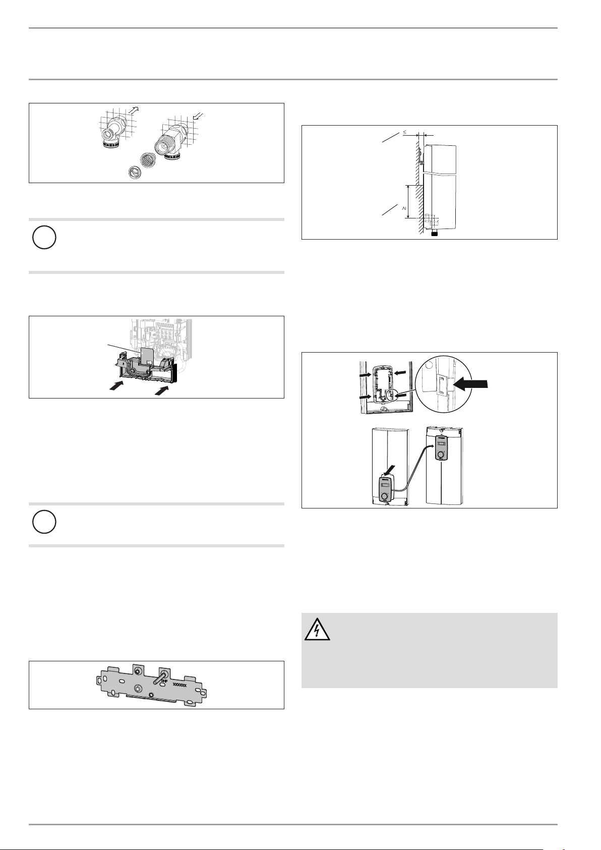
f Connect the power cable to the mains terminal.
D0000053286
2
3
1
1 Lower back panel section
2 Connection piece in the standard delivery
3 Screw
If using threaded fittings on finished walls, the lower back panel
section can also be installed after fitting the taps. To do this, carry
out the following steps:
f Cut open the lower back panel section.
f Fit the lower back panel section by bending it out at the sides
and guiding it over the pipes.
f Insert the connection pieces into the lower back panel sec-
tion from behind.
f Click the lower back panel section into place.
f Secure the lower back panel section with a screw.
!
Material losses
The cover plate of the lower back panel section must not
bend when installed.
11. Commissioning
11.1 Preparation
Internal anti-scalding protection via jumper slot
43 °C
Tmax
D0000077020
1
1 Jumper for anti-scalding protection setting
Jumper position Description
43°C
Tmax Factory setting (50°C)
No jumper Limited to 43°C
f Install the anti-scalding protection setting jumper in the re-
quired position on the upper pin strip.
CAUTION Burns
If operating with preheated water, e.g. if using a solar
thermal system, the internal anti-scalding protection and
the temperature limit Tmax, which can be set by the user,
may be exceeded.
f In this case, limit the temperature with an upstream
central thermostatic valve.
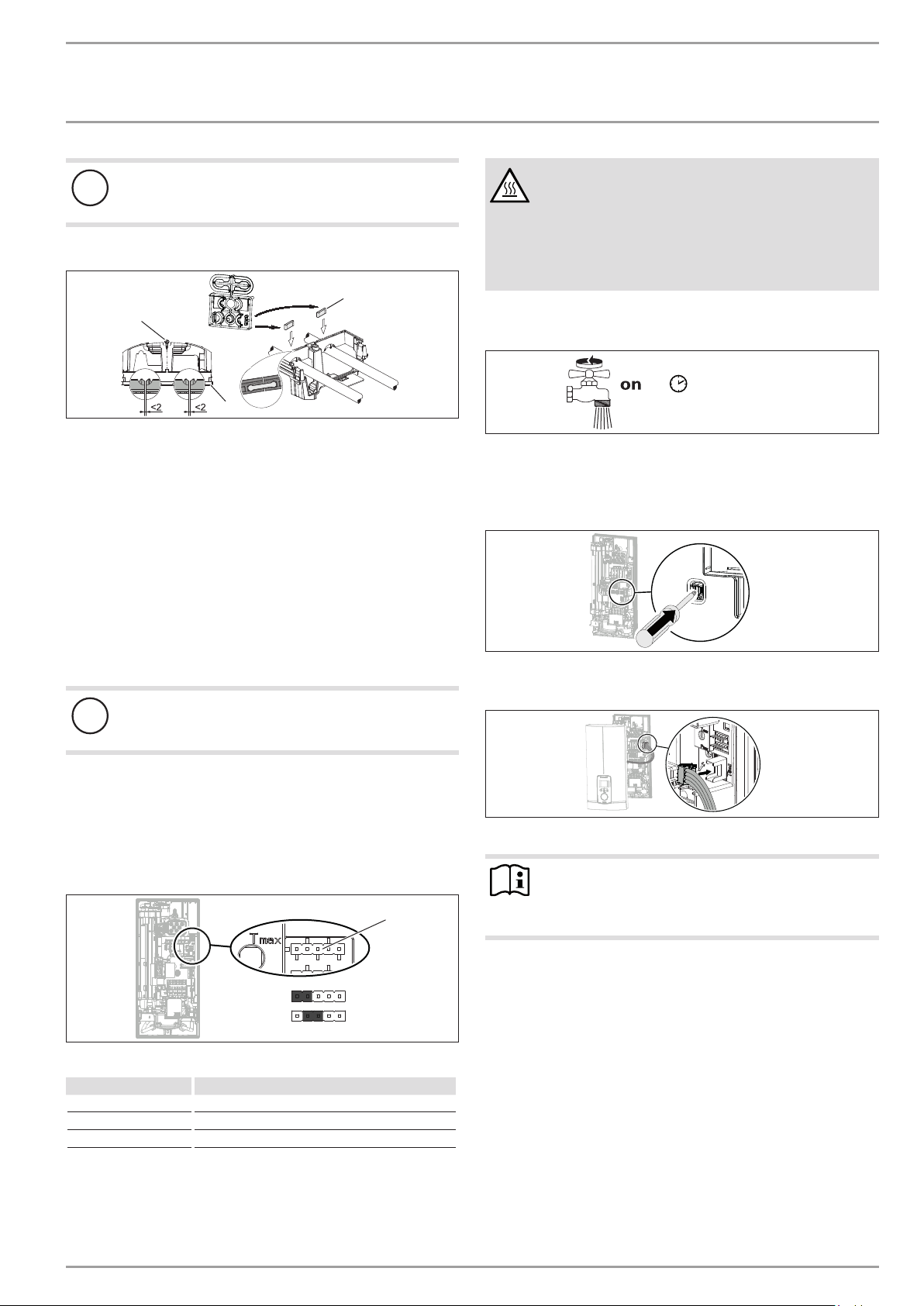
11.2 Initial start-up
≥ 60 s
D0000053277
f Open and close all connected draw-off valves several times,
until all air has been purged from the pipework and the
appliance.
f Carry out a tightness check.
D0000053278
f Activate the safety switch by firmly pressing the reset button
(the appliance is delivered with the safety switch disabled).
D0000073198
f Connect the programming unit connecting cable to the PCB.
Note
For undersink installation, the appliance cover should
be turned round for easier operation; see chapter "Alter-
native installation methods/ Pivoting appliance cover".

INSTALLATION
Appliance shutdown
12 | DEL Plus AU www.stiebel-eltron.com
Fit the appliance cover
D0000040777
1
2
3
4
1 Pipe knock-out
2 Cover guides
3 Back panel guides
4 Fixing screw (not part of the standard delivery)
f Cleanly cut or break out the knock-out openings in the appli-
ance cover. If necessary, use a file.
!
Material losses
If you cut open the wrong knock-out in the appliance
cover by mistake, you must use a new appliance cover.
Note
You can compensate for a slight connection pipe offset
using the tabs on the cover guides. If the connection pipes
are offset, do not fit any back panel guides.
f When installing connection pipes without offset, break off
the tabs on the cover guide pieces.
f Click the cover guides into place in the openings.
f Position the back panel guides on the extensions. Push them
together. Then push the guides against the back panel as far
they will go.
D0000053280
f Hook the appliance cover at the top rear into the back panel.
Pivot the appliance cover downwards. Check that the appli-
ance cover is securely seated at both top and bottom.
f Secure the appliance cover with the screw.
f Fit the fascia to the appliance cover.
f Remove the protective film from the user interface.
D0000053281
f Switch on the power supply.
11.2.1 Appliance handover
f Explain the appliance function to users and familiarise them
with how it works.
f Make the user aware of potential dangers, especially the risk
of scalding.
f Hand over the instructions.
11.3 Recommissioning
!
Material losses
To ensure that the bare wire heating system is not dam-
aged following an interruption to the water supply, the
appliance must be restarted by taking the following steps.
f Disconnect the appliance from the power supply by
removing the fuses/tripping the MCBs.
f Open the tap for a minimum of one minute until the
appliance and its upstream cold water inlet line are
free of air.
f Switch the power back ON.
12. Appliance shutdown
f Isolate all poles of the appliance from the power supply.
f Drain the appliance (see chapter "Installation/ Maintenance/
Draining the appliance").
13. Alternative installation methods
Overview of the alternative types of installation
Electrical connection IP rating
On unfinished walls, connected from above IP25
On unfinished walls, connected from below, short
power cable
IP25
On finished walls IP24
Water connection IP rating
On unfinished walls IP25
Other IP rating
Installation with offset tiles IP25
Pivoting appliance cover IP25
Horizontal installation of the appliance IP 24
WARNING Electrocution
Before any work on the appliance, disconnect all poles
from the power supply.
13.1 Electrical connection from above on unfinished
walls
140
30
D0000076507
1
1 Cable entry installation aid
f Prepare the power cable.

INSTALLATION
Alternative installation methods
www.stiebel-eltron.com DEL Plus AU | 13
D0000053282
1
1 Cable routing
f Reposition the mains terminal from the bottom to the top. To
do this, undo the fixing screw. Turn the mains terminal with
connecting cables 180° clockwise. Route the cable around
the cable guide when doing so. Secure the mains terminal in
place.
f Replace the cable grommets.
f Install the cable grommet from the top at the bottom.
f Pull the cable grommet over the cable sheath of the power
cable.
f Install the appliance on the threaded studs of the wall
mounting bracket.
f Push the back panel firmly against the wall. Lock the fixing
toggle by turning it 90° clockwise.
f Pull the cable grommets into the back panel until both lock-
ing tabs engage.
f Connect the power cable to the mains terminal.
WARNING Electrocution
The connecting wires must not protrude beyond the level
of the mains terminal.
13.2 Electrical connection on unfinished walls with
short power cable
D0000060387
f Reposition the mains terminal further downwards. To do this,
undo the fixing screw. Secure the mains terminal in place.
13.3 Electrical connection on finished walls
Note
This type of connection changes the IP rating of the ap-
pliance.
f Change the type plate. Cross out "IP25" and mark
the box "IP24". Use a ballpoint pen to do this.
A
30
D0000076506
1
1 Cable grommet
Electrical connection on finished walls Dimension A
Positioned in lower section of appliance 160
Positioned in upper section of appliance 110
f Prepare the power cable. Fit the cable grommet.
!
Material losses
If you break out the wrong knock-out in the back panel/
appliance cover by mistake, you must use a new back
panel/appliance cover.
f Cleanly cut and break out the required cable entries from the
back panel and appliance cover (for the positions, see chap-
ter "Specification/ Dimensions and connections"). Deburr any
sharp edges with a file.
f Route the power cable through the cable grommet.
f Connect the power cable to the mains terminal.
13.4 Water installation on unfinished walls
12
D0000053319
f Seal and screw in the twin connectors (not included in stand-
ard delivery).
5 Nm
24
5 Nm
24
D0000041724
2
3
3
1
1 Tee for cold water
2 Tee for domestic hot water
3 Cap
f Fit the water connections.
INSTALLATION
Alternative installation methods
14 | DEL Plus AU www.stiebel-eltron.com
D0000043291
f Fit the strainer and the plastic profile washer in the tee for
the cold water inlet.
!
Material losses
The strainer must be fitted for the appliance to function.
f When replacing an appliance, check whether the
strainer is installed.
f Screw the connection pipes from the appliance to the tee.
f Open the shut-off valve in the cold water inlet line.
D0000053275
1
1 Diffuser on lower back panel
f Fit the lower back panel section into the back panel. Check
that both locking tabs are engaged.
f Align the mounted appliance by undoing the fixing toggle,
aligning the power supply and back panel, and then re-tight-
ening the fixing toggle. If the back panel does not sit flush
against the wall, you can secure the appliance at the bottom
with an additional screw.
!
Material losses
The cover plate of the lower back panel section must not
bend when installed.
13.5 Wall mounting bracket when replacing an
appliance
An existing STIEBELELTRON wall mounting bracket may be used
when replacing appliances (except the DHF instantaneous water
heater), as long as the fixing screw is in the lower right position.
Replacing a DHF instantaneous water heater
26�02�02�0815�
f Reposition the fixing screw on the wall mounting bracket (the
fixing screw has a self-tapping thread).
f Rotate the wall mounting bracket 180° and mount it on the
wall (the DHF logo is then turned towards you).
13.6 Installation with offset tiles
110
20
2
1
D0000043278
1 Minimum contact area of the appliance
2 Maximum tile offset
f Adjust the wall clearance. Lock the back panel in place using
the fixing toggle (turn 90° clockwise).
13.7 Pivoting appliance cover
The appliance cover should be turned round for undersink in-
stallation.
D0000076838
f Remove the programming unit from the appliance cover by
pressing the locking hooks and removing the programming
unit.
f Turn the appliance cover (not the appliance) the other way
up and refit the programming unit. Push the programming
unit home in parallel until all locking tabs engage. When
engaging the locking tabs, apply counter pressure by pushing
against the appliance cover from the inside.
WARNING Electrocution
All 4locking tabs on the programming unit must click into
place. The locking tabs must be complete and undam-
aged. If the programming unit is not inserted correctly,
user protection against contact with live components
cannot be ensured.
f Insert the connecting cable plug of the programming unit
into the PCB (see chapter "Commissioning/ Initial start-up").
f Hook the appliance cover in at the bottom. Pivot the appli-
ance cover up to the back panel.
f Secure the appliance cover.
f Fit the cover onto the appliance cover.
INSTALLATION
Service information
www.stiebel-eltron.com DEL Plus AU | 15
13.8 Operation with preheated water
You can restrict the maximum inlet temperature by installing a
central thermostatic valve.
13.9 Horizontal installation of the appliance
Note
For the horizontal installation alternative, please note
the following points:
- Installation is only permissible with direct wall
mounting.
- The installation versions "Installation with offset
tiles" and "Rotated appliance cover" are not permis-
sible.
- This type of connection changes the IP rating of the
appliance. Cross out "IP25" on the type plate and
mark the box "IP24". Use a ballpoint pen to do this.
Horizontal installation
The appliance can also be mounted horizontally on the wall
(turned 90° to the left, with the water connections on the right).
The installation, water and electrical connections are described
in chapters "Standard installation" and "Installation alternatives".
1
2
D0000076919
1 Cold water inlet
2 DHW outlet
Preparation
The appliance cover must be provided with a condensate drain
opening of min. ∅5.0mm to max. ∅6.0mm at the marked po-
sition.
50
Ø 5,0
D0000076914
1 2
1 Appliance cover with opening for condensate drain
2 Back panel with additional fixing screw
f Drill a hole from the outside through the dismantled appli-
ance cover at the marked point. Alternatively, you can punch
a hole in the appliance cover from the inside at the marked
point. In this case, you must then enlarge the hole to the
required diameter from the outside. Deburr any sharp edges
with a file.
f Secure the appliance back panel with an additional screw.
!
Material losses
An appliance cover with an existing condensate drain
opening must no longer be used for vertical installation
of the appliance.
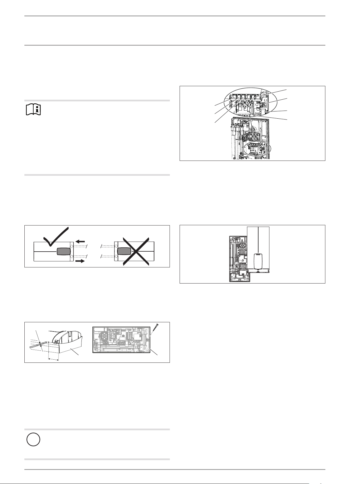
14. Service information
Overview of connections
D0000073174
1
2
3
4
5
6
7
1 Flow limit
2 Flow sensor
3 High limit safety cut-out, automatic reset
4 NTC sensor
5 Pin strip for anti-scalding protection
6 Programming unit plug-in position
7 Diagnostic traffic light
Appliance cover retainer
D0000056216

INSTALLATION
Troubleshooting
16 | DEL Plus AU www.stiebel-eltron.com
15. Troubleshooting
WARNING Electrocution
To test the appliance, it must be connected to the power
supply.
Note
When testing the appliance using the diagnostic traffic
lights, water must be flowing.
Indicator options for diagnostic traffic light (LED)
Red Illuminates in the event of a fault
Yellow Illuminates in heating mode/flashes when output limit
reached
Green Flashing: Appliance connected to power supply
Diagnostic traffic
lights (draw-off
mode)
Fault Cause Remedy
No LED illuminates Appliance does not heat up
One or more mains power phases missing Check fuses/MCBs in distribution board
Faulty PCB Replacing the function module
Green flashing,
yellow off, red off
No DHW
Appliance starting flow rate not reached; shower
head/aerator scaled up
Descale/replace the shower head/aerator
Appliance starting flow rate not reached; strainer in
cold water inlet dirty
Cleaning the strainer
Flow meter not attached Check plug-in connection; correct if necessary
Flow meter faulty or dirty Replacing the flow meter
Faulty PCB Replacing the function module
Green flashing,
yellow on, red off
No display
Loose connecting cable between PCB and program-
ming unit
Check plug-in connections; correct if necessary
Faulty connecting cable between PCB and program-
ming unit
Check connecting cable; replace if necessary
Programming unit faulty Replacing the programming unit
Faulty PCB Replacing the function module
Green flashing,
yellow on, red off
No DHW; outlet temperature
does not match set value
Tap faulty Replace tap
Faulty outlet sensor Replace the outlet sensor
Heating system faulty Replacing the function module
Faulty PCB Replacing the function module
Green flashing,
yellow flashing, red off
No DHW; outlet temperature
does not match set value
Appliance is operating at its output limit Reduce flow rate; select one of the ECO levels
Appliance is operating at its output limit Check jumper position for connected load
Heating system faulty Replacing the function module
Green flashing,
yellow off, red on
No DHW; outlet temperature
does not match set value
One or more mains power phases missing Check fuses/MCBs in distribution board
Air detection has responded Continue draw-off for >1 min
15.1 Fault code display
If there is an appliance fault, the spanner flashes on the display.
f To call up the fault code display, press the ECO button for
more than 5seconds.
Diagnostic traffic
lights (draw-off
mode)
Display shown Fault Cause Remedy
Green flashing,
yellow off, red on
Spanner flashes (display E1
and spanner in menu "Fault
code display")
No DHW; outlet temperature
does not match set value
Safety switch not activated during
"Commissioning"
Activate safety switch by pressing the
reset button firmly
Safety switch triggered by high limit
safety cut-out
Check high limit safety cut-out (plug-in
connection, connecting cable); activate
safety switch
Safety switch responds again after high
limit safety cut-out has been checked;
high limit safety cut-out faulty
Replace high limit safety cut-out; acti-
vate safety switch and draw off water
at the maximum set value for >1 min
Safety switch responds again; PCB
faulty
Replacing the function module
Green flashing,
yellow off, red on
Spanner flashes (display E2
and spanner in menu “Fault
code display”)
No DHW
PCB faulty (lead break or short circuit
in inlet sensor)
Replacing the function module
Green flashing,
yellow off, red on
Spanner flashes (display E3
and spanner in menu “Fault
code display”)
No DHW
Short circuit in outlet sensor
Check outlet sensor; replace if neces-
sary

INSTALLATION
Maintenance
www.stiebel-eltron.com DEL Plus AU | 17
16. Maintenance
WARNING Electrocution
Before any work on the appliance, disconnect all poles
from the power supply.
This appliance contains capacitors which are discharged
when disconnected from the power supply. The capacitor
discharge voltage may briefly exceed60VDC.
Draining the appliance
The appliance can be drained for maintenance work.
WARNING Burns
Hot water may escape when you drain the appliance.
f Close the shut-off valve in the cold water inlet line.
f Open all draw-off valves.
f Undo the pipe connections from the appliance.
f Store the dismantled appliance in a room free from the risk
of frost, as water residues remaining inside the appliance can
freeze and cause damage.
Cleaning the strainer
If dirty, clean the strainer in the threaded cold water fitting. Close
the shut-off valve in the cold water inlet line before removing,
cleaning and refitting the strainer.
D0000077740
2
1
1 Strainer
2 Plastic profile washer
f Remove the plastic profile washer and the strainer.
f Clean the components.
f Fit the strainer and the plastic profile washer.
17. Specification
17.1 Dimensions and connections
466
481
225
35
35
414
38
105≤ 20
140
30
b02
100
c01c06
368
116
D0000077739
DELPlusAU
b02 Entry electrical cables I On unfinished walls
c01 Cold water inlet Male thread G 1/2 A
c06 DHW outlet Male thread G 1/2 A
Alternative connection options
165
b04
b04
69
330
b04
69
325
b04
b04
b03
20
35
30
b02
D0000077736
DELPlusAU
b02 Entry electrical cables I On unfinished walls
b03 Entry electrical cables II On unfinished walls
b04 Entry electrical cables III On finished walls

INSTALLATION
Specication
18 | DEL Plus AU www.stiebel-eltron.com
17.2 Wiring diagram
3/PE ~ 380-415 V
D0000053424
1
3
4
2
1 Power PCB with integral safety switch
2 Bare wire heating system
3 High limit safety cut-out
4 Mains terminal
17.3 DHW output
The DHW output is subject to the connected power supply, the
appliance's connected load and the cold water inlet temperature.
The rated voltage and rated output can be found on the type plate.
Connected load in kW 38°C DHW output in l/min.
Rated voltage Cold water inlet temperature
380 V 400 V 415 V 5°C 10°C 15°C 20°C
DEL 13 Plus AU
12.2 5.2 6.1 7.5 9.5
13.5 5.8 6.9 8.4 10.7
14.5 6.3 7.4 9.0 11.5
DEL 18 Plus AU
16.2 7.0 8.3 10.1 12.9
18 7.8 9.2 11.2 14.3
19.4 8.4 9.9 12.0 15.4
DEL 27 Plus AU
23.5 10.2 12.0 14.6 18.7
26 11.3 13.3 16.1 20.6
28 12.1 14.3 17.4 22.2
Connected load in kW 50 °C DHW output in l/min.
Rated voltage Cold water inlet temperature
380 V 400 V 415 V 5°C 10°C 15°C 20°C
DEL 13 Plus AU
12.2 3.8 4.3 4.9 5.7
13.5 4.3 4.8 5.5 6.4
14.5 4.6 5.2 5.9 6.9
DEL 18 Plus AU
16.2 5.1 5.8 6.6 7.7
18 5.7 6.4 7.3 8.6
19.4 6.2 6.9 7.9 9.2
DEL 27 Plus AU
23.5 7.5 8.4 9.6 11.2
26 8.3 9.3 10.6 12.4
28 8.9 10.0 11.4 13.3
17.4 Application areas/ Conversion table
Specific electrical resistance and specific electrical conductivity
Standard specifica-
tion at 15 °C
20°C
25°C
Resis-
tivity
ρ≥
Conductivity σ≤
Resis-
tivity
ρ≥
Conductivity σ≤
Resis-
tivity
ρ≥
Conductivity σ≤
Ωcm mS/m μS/cm Ωcm mS/m μS/cm Ωcm mS/m μS/cm
900 111 1111 800 125 1250 735 136 1361
17.5 Pressure drop
Taps/valves
Tap pressure drop at a flow rate of 10 l/min
Mono lever mixer tap, approx. MPa 0.04 - 0.08
Thermostatic valve, approx. MPa 0.03 - 0.05
Shower head, approx. MPa 0.03 - 0.15
Sizing the pipework
When calculating the size of the pipework, an appliance pressure
drop of 0.1MPa is recommended.
17.6 Fault conditions
In the event of a fault, loads up to 80°C at a pressure of 1.0 MPa
can occur very briefly in the installation.

INSTALLATION
Specication
www.stiebel-eltron.com DEL Plus AU | 19
INSTALLATION | ENVIRONMENT AND RECYCLING
Specication
17.7 Data table
DEL 13 Plus AU DEL 18 Plus AU DEL 27 Plus AU
234470 236741 236742
Electrical data
Rated voltage V 380 400 415 380 400 415 380 400 415
Rated output kW 12.2 13.5 14.5 16.2 18 19.4 23.5 26 28
Rated current A 18.5 19.5 20 24.7 26 27 35.6 37.7 38.9
Fuse protection A 20 20 20 25 25 32 40 40 40
Frequency Hz 50/60 50/60 50 50/60 50/60 50/- 50/- 50/- 50/-
Phases 3/PE 3/PE 3/PE
Specific resistivity ρ15 ≥ Ω cm 900 900 900
Specific conductivity σ15 ≤ μS/cm 1111 1111 1111
Max. mains impedance Ω 0.459 0.436 0.42 0.331 0.315 0.304 0.221 0.21
Versions
Heating system heat generator Bare wire Bare wire Bare wire
Adjustable connected load - - -
Temperature settings °C Off, 20-50 Off, 20-50 Off, 20-50
Protection class 1 1 1
Insulating block Plastic Plastic Plastic
Cover and back panel Plastic Plastic Plastic
IP rating IP25 IP25 IP25
Colour White White White
Connections
Water connection G 1/2 A G 1/2 A G 1/2 A
Application limits
Max. permissible pressure MPa 1 1 1
Max. inlet temperature for reheating °C 50 50 50
Values
Max. permissible inlet temperature °C 50 50 50
ON l/min >2.5 >2.5 >2.5
Flow rate at 28K l/min 7.4 at 415V 9.9 at 415V 14.3 at 415V
Flow rate at 50 K l/min 4.2 at 415V 5.6 at 415V 8.0 at 415V
Pressure drop for flow rate at 50K (without flow limiter) MPa 0.04 0.06 0.14
Hydraulic data
Nominal capacity l 0.4 0.4 0.4
Dimensions
Height mm 466 466 466
Width mm 225 225 225
Depth mm 116 116 116
Weights
Weight kg 3.1 3.1 3.1
Note
The appliance conforms to IEC 61000-3-12.
Environment and recycling
We would ask you to help protect the environment.
After use,
dispose of the various materials in accordance with national
regulations.
ENVIRONMENT AND RECYCLINGENVIRONMENT AND RECYCLING
20 | DEL Plus AU www.stiebel-eltron.com
WARRANTY
Who gives the warranty
1. The warranty is given by Stiebel Eltron (Aust) Pty Ltd (A.B.N. 82
066 271 083) of 294 Salmon Street, Port Melbourne, Victoria, 3207
(“we”, “us” or “our”).
The warranty
2. This warranty applies to the Stiebel Eltron Water Heaters - Wa-
terMark Approved (the “unit”) listed within this operating and in-
stallation guide manufactured after 1 May 2015.
3. Subject to the warranty exclusions we will repair or replace, at
our absolute discretion, a faulty component in your unit free of
charge if it fails to operate in accordance with its specications
during the warranty period.
4. If we repair or replace a faulty component to your unit under this
warranty, the warranty period is not extended from the time of
the repair or replacement.
5. The warranty period commences on the date of completion of
the installation of the unit. Where the date of completion of in-
stallation is not known, then the warranty period will commence
2 months after the date of manufacture.
6. The warranty period for a unit used for domestic purposes is
shown in the table below. Domestic purposes means that the
unit is used in a domestic dwelling.
Component Warranty period
All components 5 years from the date of completion of the
installation of the unit.
7. The warranty period for a unit used for commercial purposes is
shown in the table below. Commercial purposes means that the
unit is used for a non-domestic purpose and includes but not
limited to being used in a motel, hotel, mining camp or nursing
home.
Component Warranty period
All components 1 year from the date of completion of the
installation of the unit.
Your entitlement to make a warranty claim
8. You are entitled to make a warranty claim if:
8.1. you own the unit or if you have the owner’s consent to represent
the owner of the unit;
8.2. you contact us within a reasonable time of discovering the prob-
lem with the unit;
How you make a warranty claim
9. To make a warranty claim you must provide us with the following
information:
9.1. The model number of the unit;
9.2. A description of the problem with the unit;
9.3. The name, address and contact details (such as phone number
and e-mail address) of the owner;
9.4. The address where the unit is installed and the location (e.g. in
laundry);
9.5. The serial number of the unit;
9.6. The date of purchase of the unit and the name of the seller of the
unit;
9.7. The date of installation of the unit;
9.8. A copy of the certicate of compliance when the unit was in-
stalled.
10. The contact details for you to make your warranty claim are:
Name: Stiebel Eltron (Aust) Pty Ltd
Address: 294 Salmon Street, Port Melbourne,
Victoria, 3207
Telephone: 1800 153 351
(8.00 am to 5.00 pm AEST Monday to Friday)
Contact person: Customer Service Representative
E-mail: service@stiebel-eltron.com.au
11. We will arrange a suitable time with you to inspect and test the
unit.
Warranty exclusions
12. We may reject your warranty claim if:
12.1. The unit was not installed by registered and qualied tradespeo-
ple.
12.2. The unit was not installed and commissioned:
(a) in Australia;
(b) in accordance with the Operating and Installation Guide; and
(c) in accordance with the relevant statutory and local require-
ments of the State or Territory in which the unit is installed.
12.3. The unit has not been operated or maintained in accordance
with the Operating and Installation Guide.
12.4. The unit does not bear its original Serial Number for Rating Label.
12. 5. The unit was damaged by any or any combination of the follow-
ing:
(a) normal fair wear and tear;
(b) connection to an incorrect water supply;
(c) connection to water from a bore, dam or swimming pool;
(d) connection to an incorrect power supply;
(e) connection to faulty equipment, such as damaged valves;
(f) foreign matter in the water supply, such as sludge or sedi-
ment;
(g) corrosive elements in the water supply;
(h) accidental damage;
(i) act of God, including damage by ood, storm, re, lightning
strike and the like;
(j) excessive water pressure, negative water pressure (partial
vacuum) or water pressure pulsation;
(k) ingress of vermin.
12.6. The unit was damaged before it was installed e.g. it was dam-
aged in transit.
12 .7. An unauthorised person has modified, serviced, repaired or
attempted to repair the unit without our consent.
12.8. Non genuine parts other than those manufactured or approved
by us have been used on the unit.
13. We may charge you:
13.1. for any additional transport costs if the unit is installed more than
30 kilometres from our closest authorised service technician.
13.2. for the extra time it takes our authorised service technician to
access the unit for inspection and testing if it is not sited in ac-
cordance with the Operating and Installation Guide and not
readily accessible for inspection.
13.3. for any extra costs of our authorised service technician to make
the unit safe for inspection.
14. You must ensure that access to the unit by our authorised service
technician is safe and free from obstruction.
15. Our authorised service technician may refuse to inspect and test
the unit until you provide safe and free access to it, at your cost.
16. If we reject your warranty claim in accordance with clause 12, we
may charge you for our authorised service technician’s labour
costs to inspect and test the unit.
17. In order to properly test the unit we may remove it to another
location for testing.
Australian Consumer Law
18. Our goods come with guarantees that cannot be excluded under
the Australian Consumer Law. You are entitled to a replacement
or refund for a major failure and compensation for any other rea-
sonably foreseeable loss or damage. You are also entitled to have
the goods repaired or replaced if the goods fail to be of accepta-
ble quality and the failure does not amount to a major failure.
19. The Stiebel Eltron warranty for the unit is in addition to any rights
and remedies you may have under the Australian Consumer Law.
D0000053038

www.stiebel-eltron.com DEL Plus AU | 21
NOTES

22 | DEL Plus AU www.stiebel-eltron.com
NOTES

www.stiebel-eltron.com DEL Plus AU | 23
NOTES

Deutschland
STIEBEL ELTRON GmbH & Co. KG
Dr.-Stiebel-Straße 33 | 37603 Holzminden
Tel. 05531 702-0 | Fax 05531 702-480
info@stiebel-eltron.de
www.stiebel-eltron.de
Verkauf Tel. 05531 702-110 | Fax 05531 702-95108 | info-center@stiebel-eltron.de
Kundendienst Tel. 05531 702-111 | Fax 05531 702-95890 | kundendienst@stiebel-eltron.de
Ersatzteilverkauf www.stiebel-eltron.de/ersatzteile | ersatzteile@stiebel-eltron.de
Irrtum und technische Änderungen vorbehalten! | Subject to errors and technical changes! | Sous réserve
d‘erreurs et de modifications techniques! | Onder voorbehoud van vergissingen en technische wijzigingen! |
Salvo error o modificación técnica! | Excepto erro ou alteração técnica | Zastrzeżone zmiany techniczne i
ewentualne błędy | Omyly a technické změny jsou vyhrazeny! | A muszaki változtatások és tévedések jogát
fenntartjuk! | Отсутствие ошибок не гарантируется. Возможны технические изменения. | Chyby a
technické zmeny sú vyhradené! Stand 9726
Australia
STIEBEL ELTRON Australia Pty. Ltd.
294 Salmon Street | Port Melbourne VIC 3207
Tel. 03 9645-1833 | Fax 03 9644-5091
info@stiebel-eltron.com.au
www.stiebel-eltron.com.au
Austria
STIEBEL ELTRON Ges.m.b.H.
Gewerbegebiet Neubau-Nord
Margaritenstraße 4 A | 4063 Hörsching
Tel. 07221 74600-0 | Fax 07221 74600-42
info@stiebel-eltron.at
www.stiebel-eltron.at
Belgium
STIEBEL ELTRON bvba/sprl
't Hofveld 6 - D1 | 1702 Groot-Bijgaarden
Tel. 02 42322-22 | Fax 02 42322-12
info@stiebel-eltron.be
www.stiebel-eltron.be
China
STIEBEL ELTRON (Tianjin) Electric Appliance
Co., Ltd.
Plant C3, XEDA International Industry City
Xiqing Economic Development Area
300385 Tianjin
Tel. 022 8396 2077 | Fax 022 8396 2075
info@stiebeleltron.cn
www.stiebeleltron.cn
Czech Republic
STIEBEL ELTRON spol. s r.o.
Dopraváků 749/3 | 184 00 Praha 8
Tel. 251116-111 | Fax 235512-122
info@stiebel-eltron.cz
www.stiebel-eltron.cz
Finland
STIEBEL ELTRON OY
Kapinakuja 1 | 04600 Mäntsälä
Tel. 020 720-9988
info@stiebel-eltron.fi
www.stiebel-eltron.fi
France
STIEBEL ELTRON SAS
7-9, rue des Selliers
B.P 85107 | 57073 Metz-Cédex 3
Tel. 0387 7438-88 | Fax 0387 7468-26
info@stiebel-eltron.fr
www.stiebel-eltron.fr
Hungary
STIEBEL ELTRON Kft.
Gyár u. 2 | 2040 Budaörs
Tel. 01 250-6055 | Fax 01 368-8097
info@stiebel-eltron.hu
www.stiebel-eltron.hu
Japan
NIHON STIEBEL Co. Ltd.
Kowa Kawasaki Nishiguchi Building 8F
66-2 Horikawa-Cho
Saiwai-Ku | 212-0013 Kawasaki
Tel. 044 540-3200 | Fax 044 540-3210
info@nihonstiebel.co.jp
www.nihonstiebel.co.jp
Netherlands
STIEBEL ELTRON Nederland B.V.
Daviottenweg 36 | 5222 BH 's-Hertogenbosch
Tel. 073 623-0000 | Fax 073 623-1141
info@stiebel-eltron.nl
www.stiebel-eltron.nl
New Zealand
Stiebel Eltron NZ Limited
61 Barrys Point Road | Auckland 0622
Tel. +64 9486 2221
info@stiebel-eltron.co.nz
www.stiebel-eltron.co.nz
Poland
STIEBEL ELTRON Polska Sp. z O.O.
ul. Działkowa 2 | 02-234 Warszawa
Tel. 022 60920-30 | Fax 022 60920-29
biuro@stiebel-eltron.pl
www.stiebel-eltron.pl
Russia
STIEBEL ELTRON LLC RUSSIA
Urzhumskaya street 4,
building 2 | 129343 Moscow
Tel. +7 495 125 0 125
info@stiebel-eltron.ru
www.stiebel-eltron.ru
Slovakia
STIEBEL ELTRON Slovakia, s.r.o.
Hlavná 1 | 058 01 Poprad
Tel. 052 7127-125 | Fax 052 7127-148
info@stiebel-eltron.sk
www.stiebel-eltron.sk
Switzerland
STIEBEL ELTRON AG
Industrie West
Gass 8 | 5242 Lupfig
Tel. 056 4640-500 | Fax 056 4640-501
info@stiebel-eltron.ch
www.stiebel-eltron.ch
Thailand
STIEBEL ELTRON Asia Ltd.
469 Moo 2 Tambol Klong-Jik
Amphur Bangpa-In | 13160 Ayutthaya
Tel. 035 220088 | Fax 035 221188
info@stiebeleltronasia.com
www.stiebeleltronasia.com
United Kingdom and Ireland
STIEBEL ELTRON UK Ltd.
Unit 12 Stadium Court
Stadium Road | CH62 3RP Bromborough
Tel. 0151 346-2300 | Fax 0151 334-2913
info@stiebel-eltron.co.uk
www.stiebel-eltron.co.uk
United States of America
STIEBEL ELTRON, Inc.
17 West Street | 01088 West Hatfield MA
Tel. 0413 247-3380 | Fax 0413 247-3369
info@stiebel-eltron-usa.com
www.stiebel-eltron-usa.com
A 328223-43998-9728
B 328224-43998-9728
4<AMHCMO=ciccdf>