OPERATION AND INSTALLATION
Electronically controlled instantaneous water heater
» DEL 18 AU
» DEL 27 AU
M1
Tmax
M2

2 | DEL AU www.stiebel-eltron.com
CONTENTS | SPECIAL INFORMATION
SPECIAL INFORMATION
OPERATION
1. General information �����������������������������������������3
1.1 Safety instructions ����������������������������������������������� 3
1.2 Other symbols in this documentation ����������������������� 3
1.3 Units of measurement ������������������������������������������ 3
2. Safety ���������������������������������������������������������� 4
2.1 Intended use ������������������������������������������������������ 4
2.2 General safety instructions ������������������������������������ 4
2.3 CE designation ��������������������������������������������������� 4
2.4 Test symbols ������������������������������������������������������ 4
3. Appliance description ���������������������������������������4
4. Settings and displays ����������������������������������������5
4.1 User interface ���������������������������������������������������� 5
4.2 Temperature limit (childproofing) ���������������������������� 5
4.3 Inlet temperature information �������������������������������� 6
4.4 Following an interruption of the water supply ������������ 6
5. Cleaning, care and maintenance ���������������������������6
6. Troubleshooting ����������������������������������������������6
INSTALLATION
7. Safety ���������������������������������������������������������� 7
7.1 General safety instructions ������������������������������������ 7
7.2 Instructions, standards and regulations �������������������� 7
8. Appliance description ���������������������������������������7
8.1 Standard delivery ������������������������������������������������ 7
9. Preparations ��������������������������������������������������7
9.1 Installation site ��������������������������������������������������� 8
10. Installation ����������������������������������������������������8
10.1 Standard installation �������������������������������������������� 8
10.2 Completing the installation ����������������������������������� 10
10.3 Installation options ��������������������������������������������� 11
11. Commissioning ��������������������������������������������� 13
11.1 Initial start-up ��������������������������������������������������� 13
11.2 Recommissioning ����������������������������������������������� 14
12. Shutting down the system �������������������������������� 14
13. Troubleshooting �������������������������������������������� 14
13.1 Service mode ���������������������������������������������������� 14
13.2 Indicator options for LED diagnostic traffic light ��������� 15
13.3 Fault table �������������������������������������������������������� 15
14. Maintenance ������������������������������������������������ 16
15. Specification ������������������������������������������������ 16
15.1 Dimensions and connections ��������������������������������� 16
15.2 Wiring diagram ������������������������������������������������� 17
15.3 DHW output ����������������������������������������������������� 17
15.4 Application areas/ conversion table ����������������������� 17
15.5 Pressure drop ��������������������������������������������������� 17
15.6 Fault conditions ������������������������������������������������� 17
15.7 Data table �������������������������������������������������������� 18
WARRANTY | ENVIRONMENT AND RECYCLING
SPECIAL INFORMATION
- The appliance may be used by children aged 8
and up and persons with reduced physical, sen-
sory or mental capabilities or a lack of experience
and know-how, provided that they are supervised
or they have been instructed on how to use the
appliance safely and have understood the result-
ing risks. Children must never play with the ap-
pliance. Children must never clean the appliance
or perform user maintenance unless they are
supervised.
- Ensure the appliance can be separated from the
power supply by an isolator that disconnects all
poles with at least 3mm contact separation.
- Secure the appliance as described in chapter "In-
stallation/ Installation".
- Observe the maximum permissible pressure (see
chapter "Specification/ Data table").
- Drain the appliance as described in chapter "In-
stallation/ Maintenance/ Draining the appliance".
OPERATION
General information
ENGLISH
www.stiebel-eltron.com DEL AU| 3
OPERATION
1. General information
The chapter "Operation" is intended for appliance users and qual-
ified contractors.
The chapter "Installation" is intended for qualified contractors.
Note
Read these instructions carefully before using the appli-
ance and retain them for future reference.
Pass on the instructions to a new user if required.
1.1 Safety instructions
1.1.1 Structure of safety instructions
KEYWORD Type of risk
Here, possible consequences are listed that may result
from failure to observe the safety instructions.
Steps to prevent the risk are listed.
1.1.2 Symbols, type of risk
Symbol Type of risk
!
Injury
Electrocution
Burns or scalding
1.1.3 Keywords
KEYWORD Meaning
DANGER Failure to observe this information will result in serious
injury or death.
WARNING Failure to observe this information may result in serious
injury or death.
CAUTION Failure to observe this information may result in non-seri-
ous or minor injury.
1.2 Other symbols in this documentation
Note
Notes are bordered by horizontal lines above and below
the text. General information is identified by the symbol
shown on the left.
Read these texts carefully.
Symbol
!
Material losses (appliance damage, consequential losses
and environmental pollution)
Appliance disposal
This symbol indicates that you have to do something. The ac-
tion you need to take is described step by step.
1.3 Units of measurement
Note
Unless specified otherwise, all dimensions are given in
mm.
OPERATION
Safety
4 | DEL AU www.stiebel-eltron.com
2. Safety
2.1 Intended use
This appliance is intended for domestic use. It can be used safely
by untrained persons. The appliance can also be used in a non-do-
mestic environment, e.g. in a small business, as long as it is used
in the same way.
This pressure-tested appliance is suitable for heating domestic hot
water or for reheating preheated water. The appliance can supply
one or more draw-off points.
Any other use beyond that described shall be deemed inappropri-
ate. Observation of these instructions and of instructions for any
accessories used is also part of the correct use of this appliance.
2.2 General safety instructions
CAUTION Burns
During operation, the tap can reach temperatures in
excess of 50°C, e.g. in the case of water that has been
preheated by solar energy.
There is a risk of scalding at outlet temperatures in ex-
cess of 43 °C.
!
WARNING Injury
The appliance may be used by children aged 8 and up and
persons with reduced physical, sensory or mental capa-
bilities or a lack of experience and know-how, provided
that they are supervised or they have been instructed on
how to use the appliance safely and have understood
the resulting risks. Children must never play with the
appliance. Children must never clean the appliance or
perform user maintenance unless they are supervised.
Where children or persons with limited physical, sensory or men-
tal abilities are allowed to use this appliance, we recommend a
permanent temperature limit. The limit can be set by you or a
qualified contractor:
- The temperature limit (childproofing) is user adjustable
- Anti-scalding protection can be enabled by a qualified
contractor.
!
Damage to the appliance and environment
Protect the appliance and its tap against frost.
2.3 CE designation
The CE designation shows that the appliance meets all essential
requirements according to the:
- Low Voltage Directive
- Electromagnetic Compatibility Directive
The maximum permissible mains impedance is indicated in
chapter "Specification".
2.4 Test symbols
See type plate on the appliance
Information for Australia/New Zealand:
Installation complies with standard AS/NZS 3500.4.
3. Appliance description
The electronically controlled instantaneous water heater with
automatic output matching maintains a consistent outlet tem-
perature. This is irrespective of the inlet temperature, up to the
maximum output of the appliance.
DHW temperature
The DHW outlet temperature can be variably adjusted. The select-
ed temperature is displayed.
Display backlighting
The display has white backlighting. During the draw-off process
or a temperature adjustment, backlighting is enabled.
Temperature limit (childproofing)/ anti-scalding protection
You can set the temperature limit (childproofing) individually using
the Tmax key. The selected temperature then limits the setting
range of the DHW outlet temperature.
The qualified contractor can also enable static anti-scalding pro-
tection from 43°C for you (see chapter "Alternative installation
options/ Anti-scalding protection"). The anti-scalding temperature
then functions as the upper limit for the DHW outlet temperature
and the temperature limit (childproofing).
Heating system
The heating system is suitable for hard and soft water areas; it
has low susceptibility to scale build-up. This system ensures rapid
and efficient DHW availability.
Note
The appliance is equipped with an air detector that large-
ly prevents damage to the heating system. If, during op-
eration, air is drawn into the appliance, heating output
is shut down automatically for one minute, thereby pro-
tecting the heating system.
OPERATION
Settings and displays
ENGLISH
www.stiebel-eltron.com DEL AU| 5
4. Settings and displays
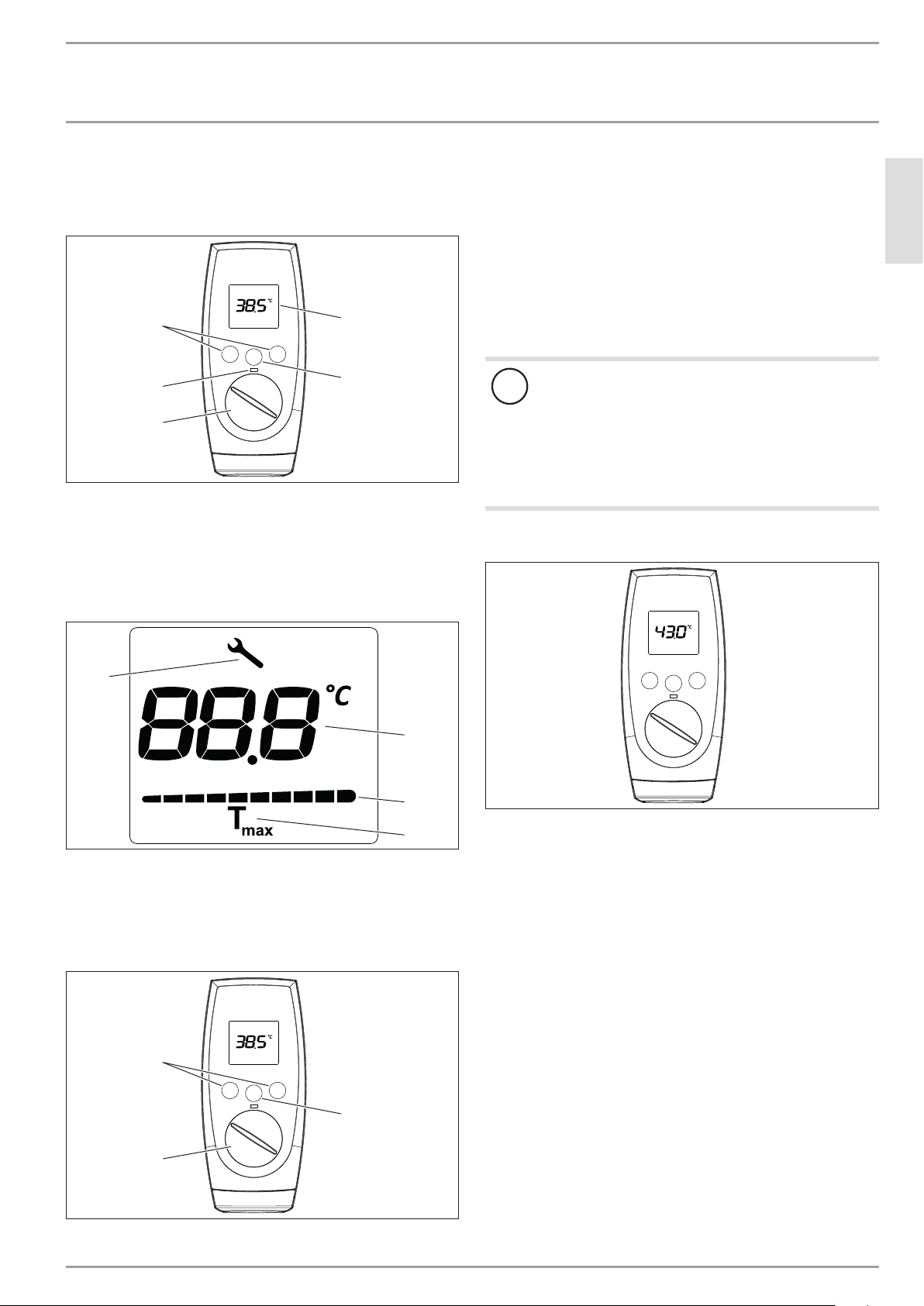
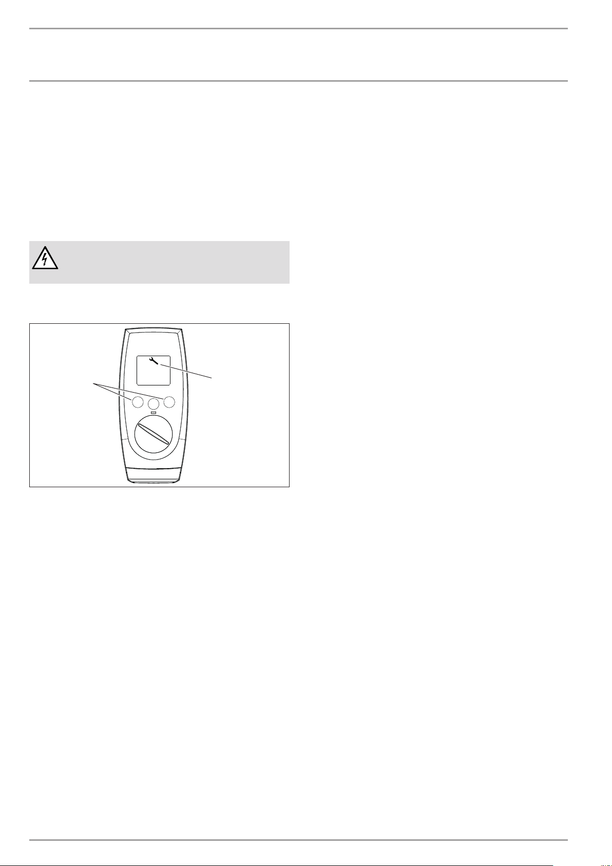
4.1 User interface
M1
Tmax
M2
D0000040726
2
3
1
5
4
1 Temperature selector
2 LED scalding risk indicator
3 Memory keys M1 and M2
4 Display
5 Temperature limit Tmax
Display symbols
1
2
3
4
D0000040989
1 In the event of an appliance fault, a spanner appears
2 Segment display for temperature setting with °C
3 Performance bar, 10 - 100%
4 Tmax, displayed when temperature limit is enabled
Setting the temperature
M1
Tmax
M2
D0000040726
2
1
3
1 Set temperature setting range 30 - 60°C (without end-stop)
35°C ... 43°C in 0.5°C increments, other temperature ranges
in 1°C increments
2 Call up preferred temperatures
3 Set the temperature limit
Memory keys M1 and M2 can each be assigned a preferred tem-
perature.
Select a preferred temperature.
Press one of the M keys for 3seconds to save the preferred
temperature . The temperature is confirmed with 1x flashing.
!
Note
If the outlet temperature is not sufficiently high when the
draw-off valve is fully open and the temperature selector
is set to maximum, then more water is flowing through
the appliance than can be heated by the heating system
(working at maximum output).
Reduce the water volume at the draw-off valve until
the preferred temperature delivery is achieved.
4.2 Temperature limit (childproofing)
M1
Tmax
M2
D0000040981
The temperature limit can be individually set between 30°C and
50°C.
Enabling the temperature limit (childproofing)
Press and hold the Tmax key for >6seconds. The set value
display flashes and the current temperature limit is shown.
The value for the temperature limit can be changed while
the display is flashing. If no key is pressed for 10seconds,
the display stops flashing and the value is stored. The display
then shows the set value and the Tmax symbol.
Disabling the temperature limit (childproofing)
Press and hold the Tmax key for >6seconds.
The Tmax symbol on the display is no longer shown.
OPERATION
Cleaning, care and maintenance
6 | DEL AU www.stiebel-eltron.com
4.3 Inlet temperature information
If the inlet temperature is higher than the preferred temperature,
e.g. if water has been preheated by solar energy, the display alter-
nates between showing "hot" and the measured inlet temperature.
The LED scalding risk indicator also flashes.
Recommended setting for operation with a thermostatic valve
and water preheated by solar energy
Set the temperature at the appliance to the max.
temperature.
4.4 Following an interruption of the water supply
!
Material losses
Following an interruption of the water supply the appli-
ance must be recommissioned by carrying out the follow-
ing steps, in order to prevent the destruction of the bare
wire heating system.
Disconnect the appliance from the power supply by
removing the fuses/tripping the MCBs.
Open the tap for one minute until the appliance and
its upstream cold water inlet line are free of air.
Switch the mains power back ON again.
5. Cleaning, care and maintenance
Never use abrasive or corrosive cleaning agents. A damp
cloth is sufficient for cleaning the appliance.
Check the taps regularly. Limescale deposits at the spouts
can be removed using commercially available descaling
agents.
6. Troubleshooting
Fault Cause Remedy
The appliance will
not start despite the
DHW valve being
fully open.
There is no voltage in the
appliance.
Check the fuses/MCBs in
your fuse box/distribution
panel.
The aerator in the tap or
the shower head is scaled
up or contaminated.
Clean and/or descale the
aerator or shower head.
The water supply has been
interrupted.
Vent the appliance and the
cold water inlet line (see
chapter "Settings / Follow-
ing an interruption to the
water supply").
Cold water flows
briefly while hot
water is being
drawn.
The air sensor detects air
in the water and the ap-
pliance's heating output is
briefly switched off.
The appliance restarts au-
tomatically after 1minute.
The temperature at
the appliance cannot
be set to >43°C.
The Tmax childproofing is
enabled.
Disable the childproofing
(see chapter "Appliance
description")
The anti-scalding protec-
tion in the appliance is
enabled.
Your qualified contractor
can disable the anti-scald-
ing protection for you.
If you cannot remedy the fault, notify your qualified contractor.
To facilitate and speed up your enquiry, please provide the serial
number from the type plate (000000-0000-000000):
No.: 000000-0000-000000
DEL ... AU
26�02�02�1125�
ENGLISH
www.stiebel-eltron.com DEL AU| 7
INSTALLATION
Safety
INSTALLATION
7. Safety
Only a qualified contractor should carry out installation, commis-
sioning, maintenance and repair of the appliance.
7.1 General safety instructions
We guarantee trouble-free function and operational reliability only
if original accessories and spare parts intended for the appliance
are used.
Flow pressure
If the flow rate is not sufficient to switch on the appliance even
when the tap is open, remove the flow limiter and replace it with
the plastic profile washer supplied.
If required, the pressure in the water installation can also be
raised.
Note
For the thermostatic valve to function correctly, the flow
limiter for this valve must not be replaced with the plastic
profile washer.
!
Material losses
Observe the maximum inlet temperature. Higher tem-
peratures may damage the appliance. You can limit the
maximum inlet temperature by installing a central ther-
mostatic valve.
7.2 Instructions, standards and regulations
Note
Observe all applicable national and regional regulations
and instructions.
- The protection rating IP 25 (hoseproof) can only be ensured
with a correctly fitted cable grommet.
- The specific electrical resistance of the water must not fall
below that stated on the type plate. In a linked water net-
work, factor in the lowest electrical resistance of the water
(see chapter "Specification/ Application areas"). Your water
supply utility will advise you of the specific electrical water
resistance or conductivity.
8. Appliance description
8.1 Standard delivery
The following are delivered with the appliance:
- Wall mounting bracket
- Installation template
- 2 plugs
- 2 extensions
- 2 caps
- 2 tees
- 8 flat gaskets
- Strainer
- 2 flow limiters
- Plastic profile washer
- Plastic connection pieces / installation aid
- Cover and back panel guides
9. Preparations
Flush the water line thoroughly.
Taps/valves
Use appropriate pressure-tested taps. Open taps are not
permitted.
A safety valve is not required.
Permissible water pipe materials
- Cold water inlet pipe:
Galvanised steel pipe, stainless steel pipe, copper pipe or
plastic pipe
- DHW outlet pipe:
Stainless steel pipe, copper pipe or plastic pipe
!
Material losses
If plastic pipework systems are used, take into account
the maximum inlet temperature and the maximum pres-
sure (see chapter "Specification/ Data table").
Flow rate
Ensure that the flow rate (see chapter "Specification/ Data
table", On) is sufficient for switching on the appliance.
Increase the mains water pressure if the required flow rate is
not sufficient with an open draw-off valve.
Flexible water connection lines
If the appliance is installed with flexible water connection
lines, ensure that the pipe bends do not become twisted.
Pipe bends have a bayonet fitting and are installed inside the
appliance.
Secure the back panel with an additional screw at the
bottom.
8 | DEL AU www.stiebel-eltron.com
INSTALLATION
Installation
9.1 Installation site
!
Material losses
Only install the appliance in rooms free from the risk of
frost.
Always install the appliance vertically near the draw-off
point.
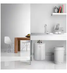
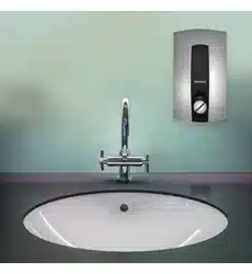
The appliance is suitable for undersink and oversink installations.
Note
Mount the appliance on a sufficiently load-bearing wall.
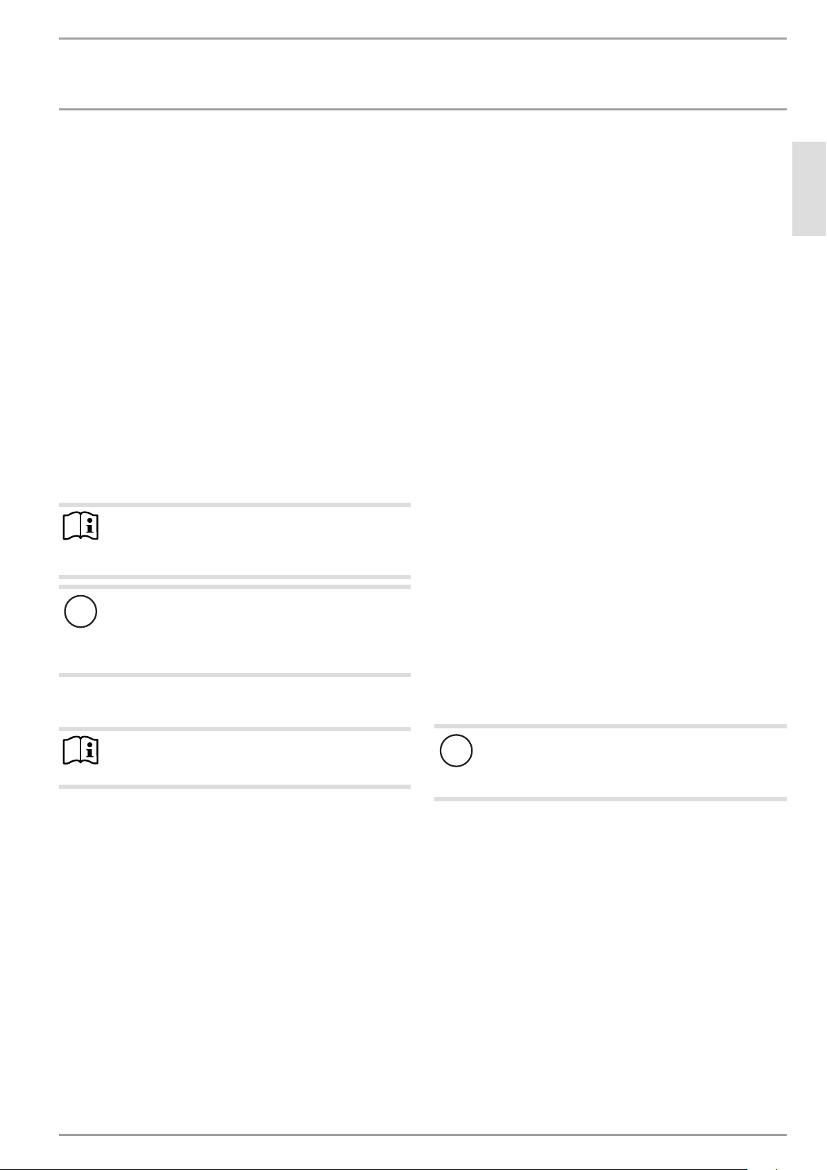
Undersink installation
1
2
D0000040728
1 Cold water inlet
2 DHW outlet
Oversink installation
1
2
D0000040736
1 Cold water inlet pipe
2 DHW outlet pipe
10. Installation
10.1 Standard installation
- Electrical connection in the lower section of the appliance for
installation on unfinished walls
- Water connection for installation on finished walls
- For the appliance with adjustable connected load, the middle
load is preset.
For further installation options, see chapter "Installation options".
elect ro nic c omfor
t
D0000040738
Open the appliance.
26�02�02�1101
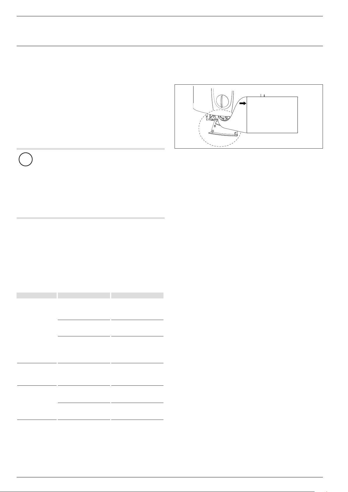
Remove the back panel by pressing the two locking hooks
and pulling the lower part of the back panel forwards.
26�02�02�0810�
Mount the wall mounting bracket.
Align the installation template based on the existing electrical
connection when marking out the drill holes (wall mounting and
lower back panel).
If you want to adapt the existing water connections, take the di-
mensions from the drawing when marking out the drill holes; see
chapter "Specification/ Dimensions and connections". In this case,
check beforehand that the electrical connection lies within one of
the areas marked on the installation template.
ENGLISH
www.stiebel-eltron.com DEL AU| 9
INSTALLATION
Installation
160
30
1
26�02�02�0824�
1 Installation aid
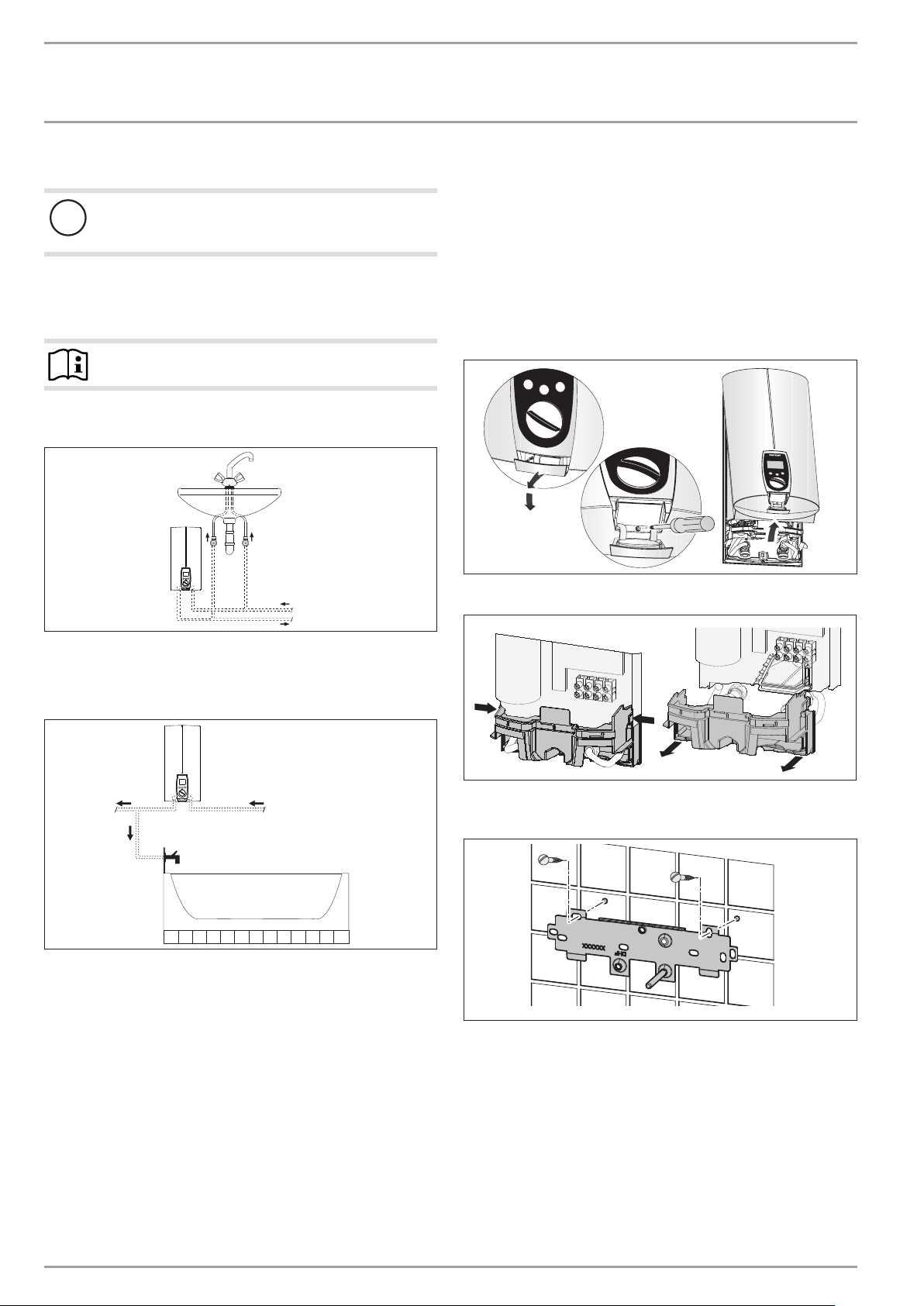
Prepare the power cable.
Preparing the water connection
!
Material losses
Carry out all water connection and installation work in
accordance with regulations.
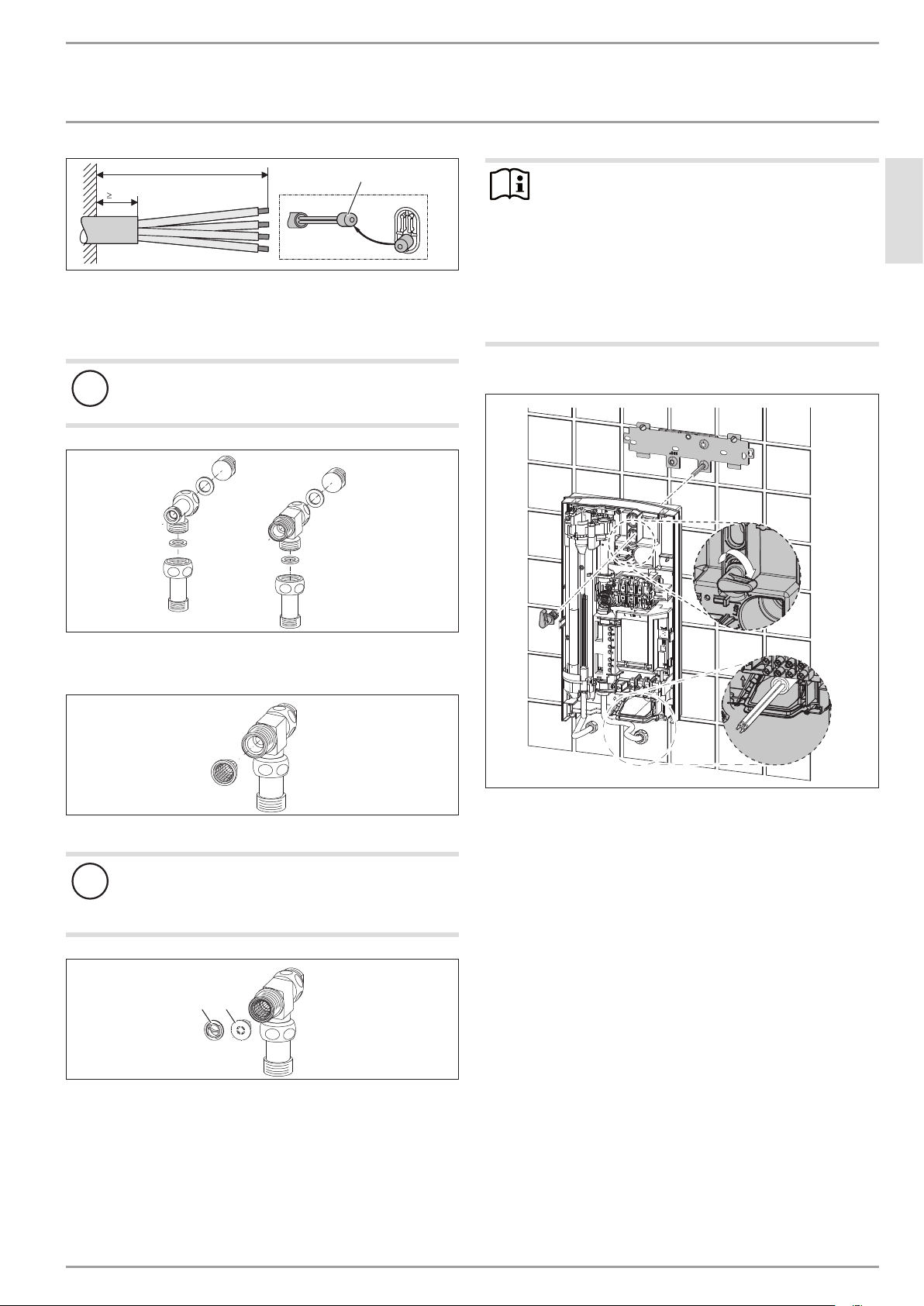
D0000041720
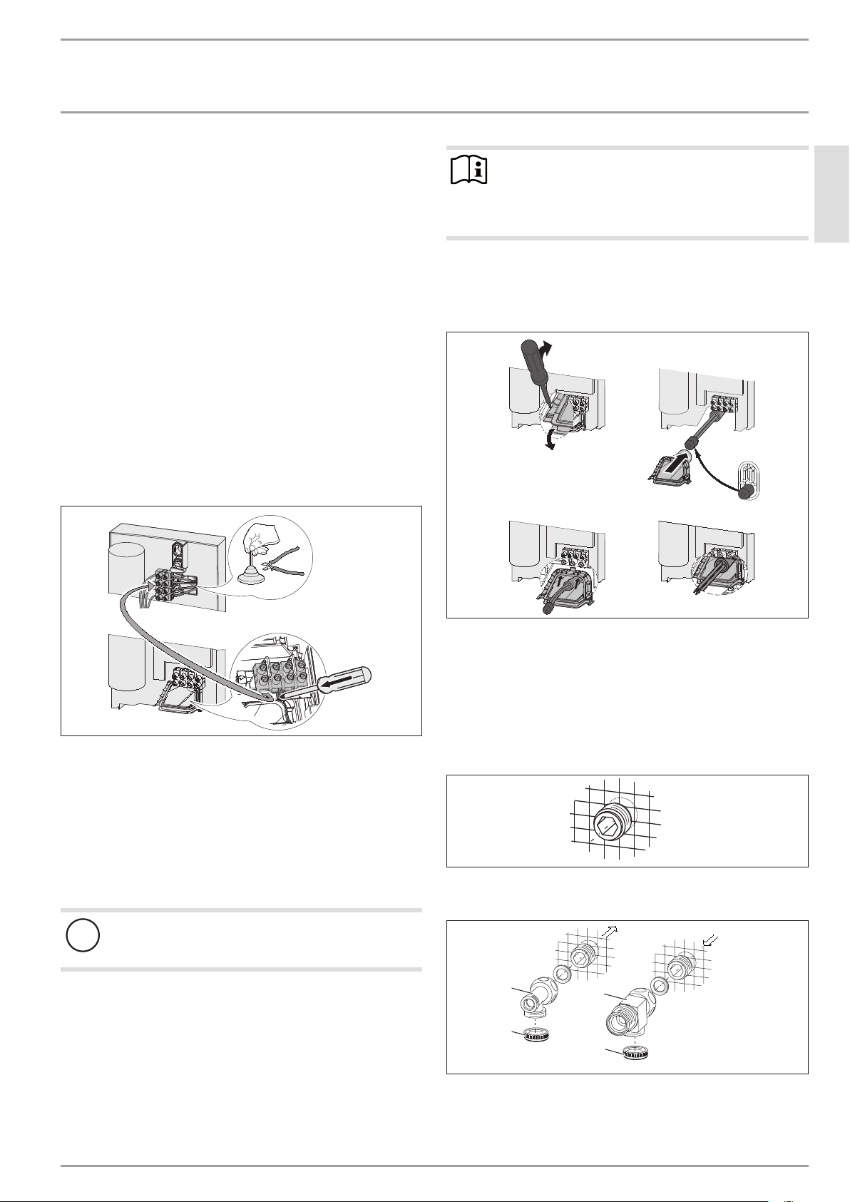
Remove the caps from the tees.
Fit the plugs and the extensions with gaskets.
D0000041721
Fit the strainer in the tee for the cold water inlet.
!
Damage to the appliance and environment
The strainer must be fitted for the appliance to function.
When replacing the appliance, check that the strain-
er is present.
D0000041722
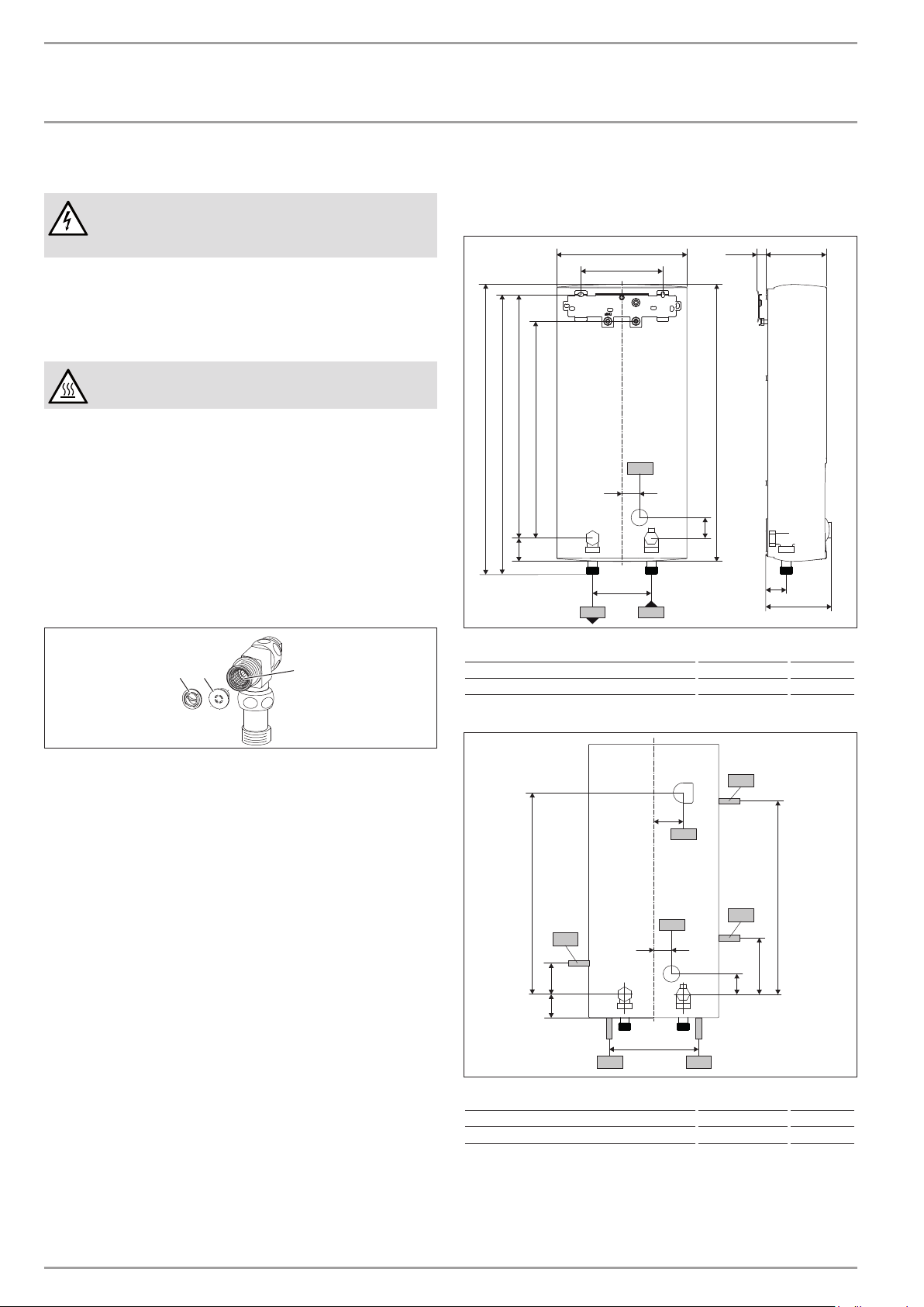
12
1 Flow limiter
2 Plastic profile washer
Fit the flow limiter or the plastic profile washer.
Note
Install the blue flow limiter (7.5l/min) as standard.
Use the brown flow limiter (12l/min) in the follow-
ing instances:
- With an increased cold water inlet temperature, e.g.
in the case of water preheated by solar energy.
- When using the appliance for showering.
With low water pressure.The pressure drop can be
reduced by replacing the flow limiter with the plastic
profile washer provided.
Installing the appliance
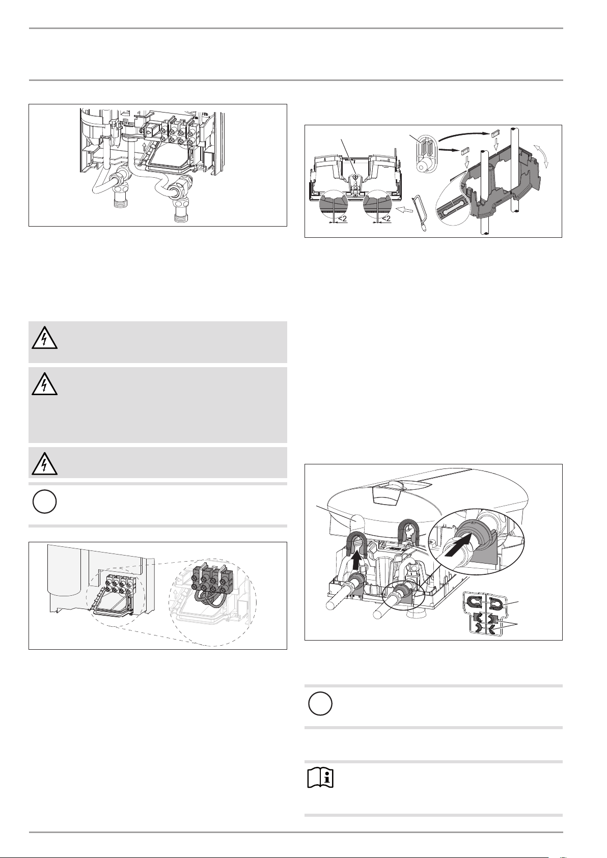
26�02�02�1336
For easy installation, push the cable grommet of the upper
electrical connection into the back panel from behind.
Remove the transport plugs from the water connections.
Remove the fixing toggle from the upper part of the back
panel.
Route the power cable through the cable grommet from be-
hind, until the power cable rests against the cable sheath.
Align the power cable.
If the cross-section is >6mm², enlarge the hole in the cable
grommet.
Press the appliance over the threaded stud of the wall
mounting bracket. When doing so, push through the soft
seal in the back panel of the appliance. If necessary, use a
screwdriver.
Push the fixing toggle on to the threaded stud of the wall
mounting bracket.
Push the back panel of the appliance on to the wall. Turn the
fixing toggle 90° clockwise to lock the appliance in place.
10 | DEL AU www.stiebel-eltron.com
INSTALLATION
Installation
D0000041723
Screw the pre-assembled parts with flat gaskets to the cold
water and DHW pipes of the appliance.
Fit the cold water inlet pipe and the DHW outlet pipe from
the pipework with flat gaskets to the extensions from the
appliance.
Making the electrical connection
WARNING Electrocution
Carry out all electrical connection and installation work
in accordance with relevant regulations.
WARNING Electrocution
Connection to the power supply is only permissible in the
form of a permanent connection in conjunction with the
removable cable grommet. Ensure the appliance can be
separated from the power supply by an isolator that dis-
connects all poles with at least 3mm contact separation.
WARNING Electrocution
Ensure that the appliance is earthed.
!
Damage to the appliance and environment
Observe the type plate. The specified voltage must match
the mains voltage.
26�02�02�1122�
Connect the power cable to the mains terminal (see chapter
"Specification/ Wiring diagram"). The specified voltage must
match the mains voltage.
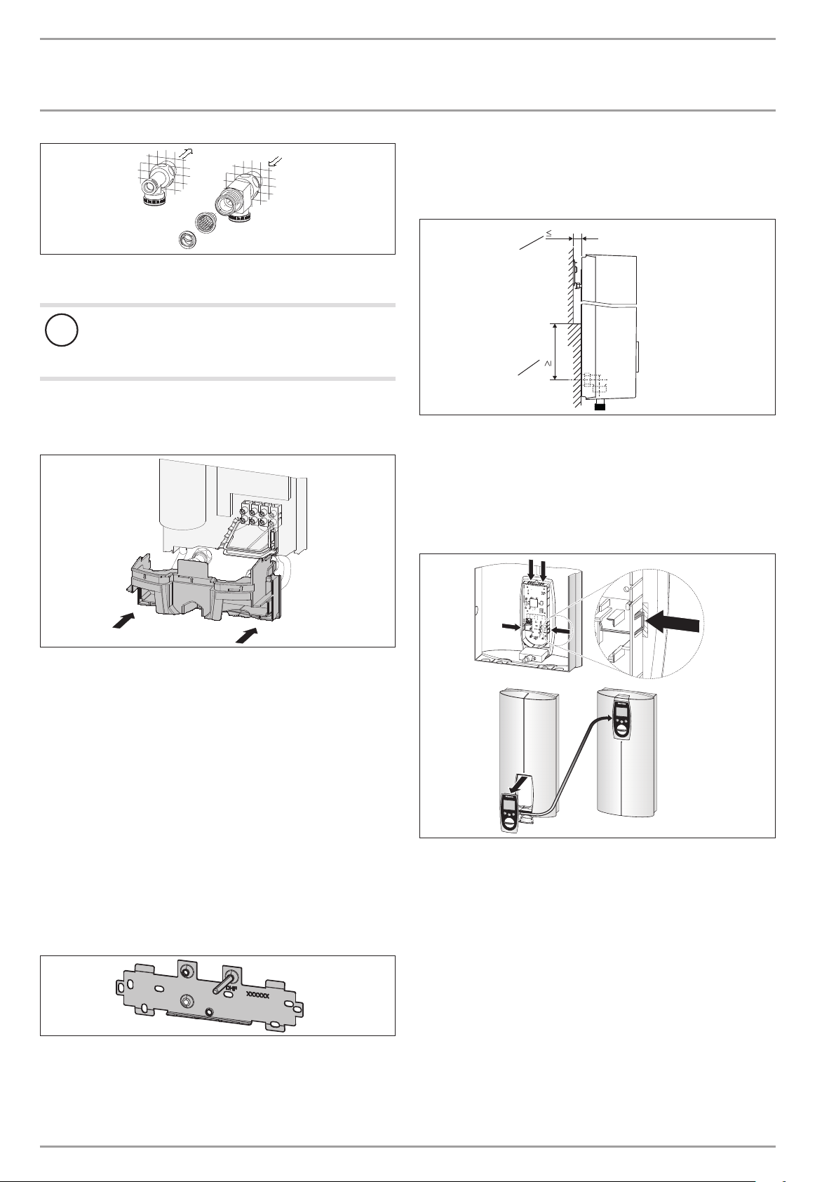
Lower back panel installation
1
2
26�02�02�1080
1 Connection pieces delivered in the pack
2 Screw
Cut open the lower part of the back panel (see illustration).
Fit the lower back panel by bending it out at the sides and
guiding it over the pipes.
Insert the connection pieces into the lower back panel from
behind.
Click the lower back panel into place.
Align the mounted appliance by loosening the fixing toggle,
aligning the power supply and back panel, and then re-tight-
ening the fixing toggle.
Secure the lower back panel with a screw.
10.2 Completing the installation
Open the shut-off valve in the cold water inlet line.
Fitting the sealing elements for the appliance cover
1
2
3
D0000040777
1 Pipe aperture
2 Cover guides
3 Back panel guides
!
Material losses
If you cut open the wrong knock-out in the appliance
cover by mistake, you must use a new appliance cover.
Cleanly cut or break out the knock-out openings in the appli-
ance cover. If necessary, use a file.
Note
You can compensate for a slight connection pipe offset
using the tabs on the cover guides. If the connection pipes
are offset, do not fit any back panel guides.
ENGLISH
www.stiebel-eltron.com DEL AU| 11
INSTALLATION
Installation
When installing connection pipes that are not offset, break
off the tabs on the cover guides.
Click the cover guides into place in the pipe apertures.
Position the back panel guides on the extensions. Push them
together. Then push the guides until they are resting against
the back panel.
10.3 Installation options
- Electrical connection from above on unfinished walls
- Electrical connection for finished walls
- Large cross-section for electrical connection from below
- Water installation on unfinished walls
- Wall mounting bracket when replacing an appliance
- Installation with offset tiles
- Pivoting appliance cover
- Operation with preheated water
- Anti-scalding protection/ temperature limit
Electrical connection from above on unfinished walls
26�02�02�1123�
Cut open the cable grommet for the power cable.
Push down the locking hook to secure the mains terminal.
Pull out the mains terminal.
Reposition the mains terminal in the appliance from the
bottom to the top and secure the mains terminal by sliding it
under the locking hook.
Lay the control wires below the wire guide.
Power cable for finished walls
!
Material losses
If you cut open the wrong knock-out in the appliance
cover by mistake, you must use a new appliance cover.
Cut or break out the required entries in the back panel and
appliance cover cleanly (for positions, see chapter "Specifica-
tion/ Dimensions and connections"). If necessary, use a file.
Route the power cable through the cable grommet. Connect
the power cable to the mains terminal.
Note
This type of connection changes the protection rating of
the appliance.
Change the type plate. Cross out "IP 25" and mark
the box "IP 24". Please use a ballpoint pen to do this.
Large cross-section for electrical connection from below
If you use cables with a large cross-section, you can fit the cable
grommet after the appliance has been installed.
1.
3.
4.
2.
26�02�02�1124�
Before installing the appliance, use a screwdriver to push out
the cable grommet.
Slide the cable grommet over the power cable. For this, use
the installation aid. If the cross-section is >6mm², enlarge
the hole in the cable grommet.
Push the cable grommet into the back panel.
Water installation on unfinished walls
26�02�02�0798
Seal and screw in the twin connectors (not included in stand-
ard delivery).
D0000041724
2
3
1
3
1 Tee for cold water
2 Tee for domestic hot water
3 Cover
Fit the water connections.
12 | DEL AU www.stiebel-eltron.com
INSTALLATION
Installation
D0000043291
Fit the strainer and the plastic profile washer in the tee for
the cold water inlet.
!
Damage to the appliance and environment
The strainer must be fitted for the appliance to function.
When replacing the appliance, check that the strain-
er is present.
Screw the connection pipes from the appliance with flat gas-
kets to the tee.
Open the shut-off valve in the cold water inlet line.
26�02�02�1102�
Fit the lower part of the back panel. Ensure that it clicks into
place.
Align the mounted appliance by loosening the fixing toggle,
aligning the power supply and back panel, and then re-tight-
ening the fixing toggle. If the back panel of the appliance is
not flush, the appliance can be secured at the bottom with an
additional screw.
Wall mounting bracket when replacing an appliance
When replacing an appliance, you can use an existing wall mount-
ing bracket of a StiebelEltron appliance (except for a DHF instan-
taneous water heater).
Press the appliance over the threaded stud of the existing
wall mounting bracket. When doing so, push through the soft
seal in the back panel of the appliance. If necessary, use a
screwdriver.
DHF replacement
26�02�02�0815�
Remove the DHF wall mounting bracket.
Take the new wall mounting bracket and move the thread-
ed stud to the position marked with DHF (the stud has a
self-tapping thread).
Rotate the wall mounting bracket 180° and mount it on the
wall. Use the existing drill holes.
Installation with offset tiles
110
20
2
1
D0000043278
1 Minimum contact area of the appliance
2 Maximum tile offset
Adjust the wall clearance. Lock the back panel with the fixing
toggle by turning it 90° clockwise.
Pivoting appliance cover
You can rotate the appliance cover for undersink installation.
electr o nic
comfor t
electr
onic comfor
t
D0000040745
Remove the programming unit from the appliance cover by
pressing the locking hooks and taking out the programming
unit.
Turn the appliance cover (not the appliance) and refit the
programming unit, ensuring that all locking hooks click into
place. When clicking the locking hooks into place, make sure
you press against the inner side of the appliance cover (shad-
ed area).
Plug the set value transducer cable into the PCB (see chapter
"Commissioning/ Initial start-up").
Hook the appliance cover in at the bottom. Pivot it up to the
back panel.
Ensure the all-round seal of the back panel is firmly seated
by pushing the cover gently forwards and back.
Secure the appliance cover.
ENGLISH
www.stiebel-eltron.com DEL AU| 13
INSTALLATION
Commissioning
Operation with preheated water
You can limit the maximum inlet temperature by installing a cen-
tral thermostatic valve.
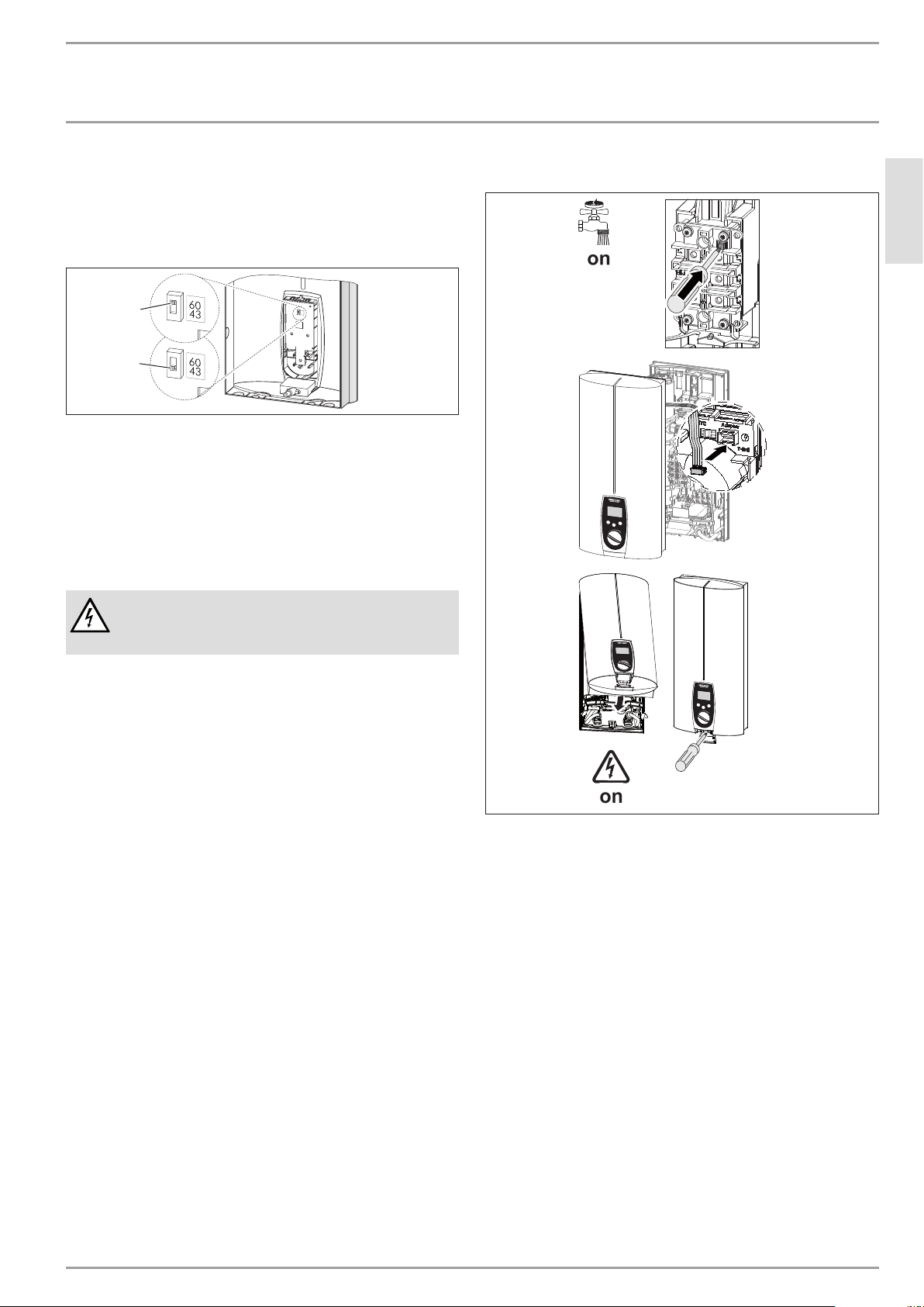
Anti-scalding protection/ temperature limit
60
43
D0000040985
2
1
1 Position 43: Maximum temperature setting 43°C
2 Position 60: No temperature limit, for temperature setting
range, see chapter "Specification/Data table".
Remove the appliance cover.
Slide the switch to the required position.
Fit the appliance cover.
11. Commissioning
WARNING Electrocution
Commissioning may only be carried out by a qualified
contractor in accordance with safety regulations.
11.1 Initial start-up
e
l
e
c
t
r
o
n
i
c
c
o
m
f
o
r
t
D0000040746
Open and close all connected draw-off valves several times,
until all air has been vented from the pipework and the
appliance.
Check for leaks in the appliance screw joints.
Activate the safety pressure limiter for flow pressure by
firmly pressing in the reset button (the appliance is delivered
with the safety pressure limiter disabled).
Push the temperature selector plug into the "set tempera-
ture" PCB.
Fit the appliance cover and secure with a screw.
Switch the mains power ON.
Check the function of the appliance.
Remove the protective foil from the control fascia.
Appliance handover
Explain the appliance function to users and familiarise them
with its operation.
Make users aware of potential dangers, especially the risk of
scalding.
Hand over these instructions.
14 | DEL AU www.stiebel-eltron.com
INSTALLATION
Shutting down the system
11.2 Recommissioning
See chapter "Settings and displays / Following an interruption to
the water supply"
12. Shutting down the system
Isolate all poles of the appliance from the power supply.
Drain the appliance (see chapter "Maintenance").
13. Troubleshooting
WARNING Electrocution
In order to check the appliance it must be connected to
the power supply.
13.1 Service mode
M1
Tmax
M2
D0000040982
1
2
1 Memory keys M1 and M2
2 Spanner symbol
The spanner symbol is displayed in the event of a fault.
Activate customer service mode by pressing and holding
down both memory keys M1 and M2 for >6seconds.
Disable customer service mode by briefly pressing one of the
three keys. Service mode is automatically terminated after
30seconds of inactivity.
Fault displays
--- No display, there is no fault
ntc Outlet sensor malfunction
ELE Faulty PCB
ENGLISH
www.stiebel-eltron.com DEL AU| 15
INSTALLATION
Troubleshooting
13.2 Indicator options for LED diagnostic traffic light
Indicator options
Red Illuminates in the event of a fault
Yellow Illuminates during heating mode
Green Flashing: Appliance is supplied with mains power
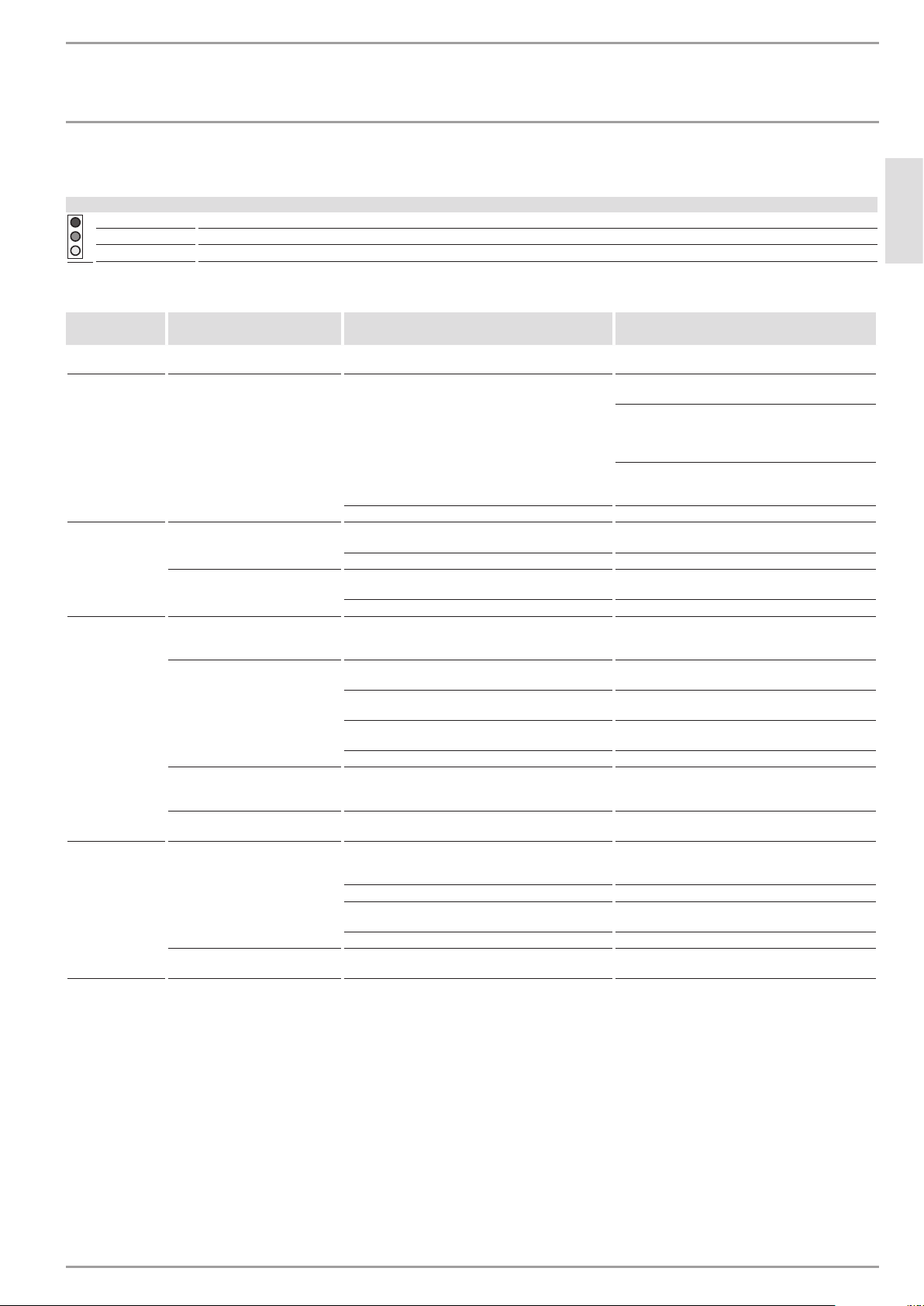
13.3 Fault table
LED diagnostic
traffic light
Fault Cause Remedy
No display No hot water. The fuse/MCB in the fuse box has blown/responded. Check the fuses/MCBs in your fuse box/distribution
panel.
The safety pressure limiter has responded.
Remove the cause of the fault (e.g. faulty pressure
washer).
Protect the heating system against overheating by
opening a draw-off valve downstream of the appli-
ance for one minute. This depressurises and cools
down the heating system.
Activate the safety pressure limiter at flow pressure
by pressing the reset button; see also chapter "Com-
missioning/ Initial start-up".
The PCB is faulty. Check the PCB, replace if required.
Flashing green
light
The appliance does not start.
Inadequate flow rate. Descale/ clean the connected aerator/ shower
head.
Inadequate flow rate. Clean the strainer in the water inlet.
No hot water at flow rate
>3l/min.
The flow sensor (DFE) plug has not been inserted. Plug the flow sensor plug back in.
The flow sensor (DFE) is faulty. Check the flow sensor and replace if required.
Flashing green
light and steady
yellow light
No hot water at flow rate
>3l/min.
The high limit safety cut-out has responded or its
lead is broken.
Check the appliance and the high limit safety cut-
out.
The set temperature is not
achieved.
One phase down. Check the fuses/MCBs in your fuse box/distribution
panel.
The heating system is faulty. Measure the resistance of the heating system and
replace if required.
The outlet temperature sensor is faulty. Check the outlet temperature sensor and replace if
required.
The appliance is at its output limit. Reduce the flow rate or install the flow limiter.
The outlet temperature is approx.
45°C, irrespective of the set value
transducer
The set value transducer or connecting cable is faulty,
or the connecting cable is not attached.
Attach the connecting cable; replace the set value
transducer if required.
A set temperature of >43°C is not
achieved.
The temperature limit (childproofing)/ anti-scalding
protection is enabled.
Disable the temperature limit (childproofing)/ an-
ti-scalding protection.
Flashing green
light and steady
red light
No hot water.
The outlet temperature sensor is faulty.
Check the outlet temperature sensor and replace if
required.
The cold water sensor is faulty. Check the PCB, replace if required.
The air sensor detects the presence of air in the water
and briefly interrupts the heating output.
The appliance restarts after one minute.
The flow rate is >25l/min. Reduce the flow rate or install the flow limiter.
Selected temperatures above 45°C
are not achieved.
The cold water inlet temperature is above 45°C (e.g.
in the case of water preheated by solar energy).
Reduce the cold water inlet temperature to the ap-
pliance.
16 | DEL AU www.stiebel-eltron.com
INSTALLATION
Maintenance
14. Maintenance
WARNING Electrocution
Before any work on the appliance, disconnect all poles
from the power supply.
Draining the appliance
You can drain the appliance for maintenance work or to protect
it from frost.
CAUTION Scalding
Hot water may escape when draining the appliance.
Close the shut-off valve in the cold water inlet line.
Open all draw-off valves.
Undo the water connections on the appliance.
Store the dismantled appliance in a room free from the risk
of frost, as water residues remaining inside the appliance can
freeze and cause damage.
Cleaning the strainer
A strainer is located in the tee from the cold water inlet pipe. In
case of contamination, you can remove this strainer and clean it.
D0000041722
1 32
1 Flow limiter or
2 Plastic profile washer
3 Strainer
Remove the flow limiter or plastic profile washer (selected
during installation).
Remove the strainer and clean the components.
Fit the strainer and the plastic profile washer or flow limiter.
15. Specification
15.1 Dimensions and connections
473
478
100
414
44
105≤ 20225
140
30
35
35
114
368
b02
c01c06
493
D0000043287
b02 Entry electrical cables I
c01 Cold water inlet Male thread G 1/2 A
c06 DHW outlet Male thread G 1/2 A
Alternative connection options
165
50
44
30
35
72
325
338
47
b03
b02
b04
b04
b04
b04
b04
D0000043288
b02 Entry electrical cables I
b03 Entry electrical cables II
b04 Entry electrical cables III
ENGLISH
www.stiebel-eltron.com DEL AU| 17
INSTALLATION
Specication
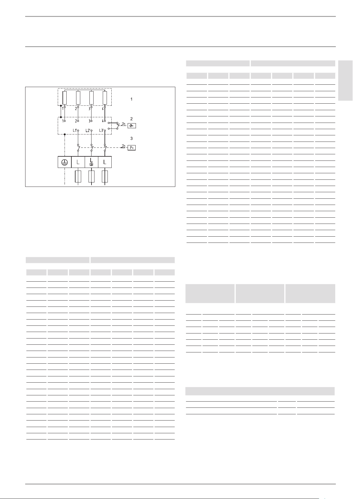
15.2 Wiring diagram
3/PE ~ 380-415 V
85�02�02�0005�
1 Heater
2 High limit safety cut-out
3 Safety pressure limiter
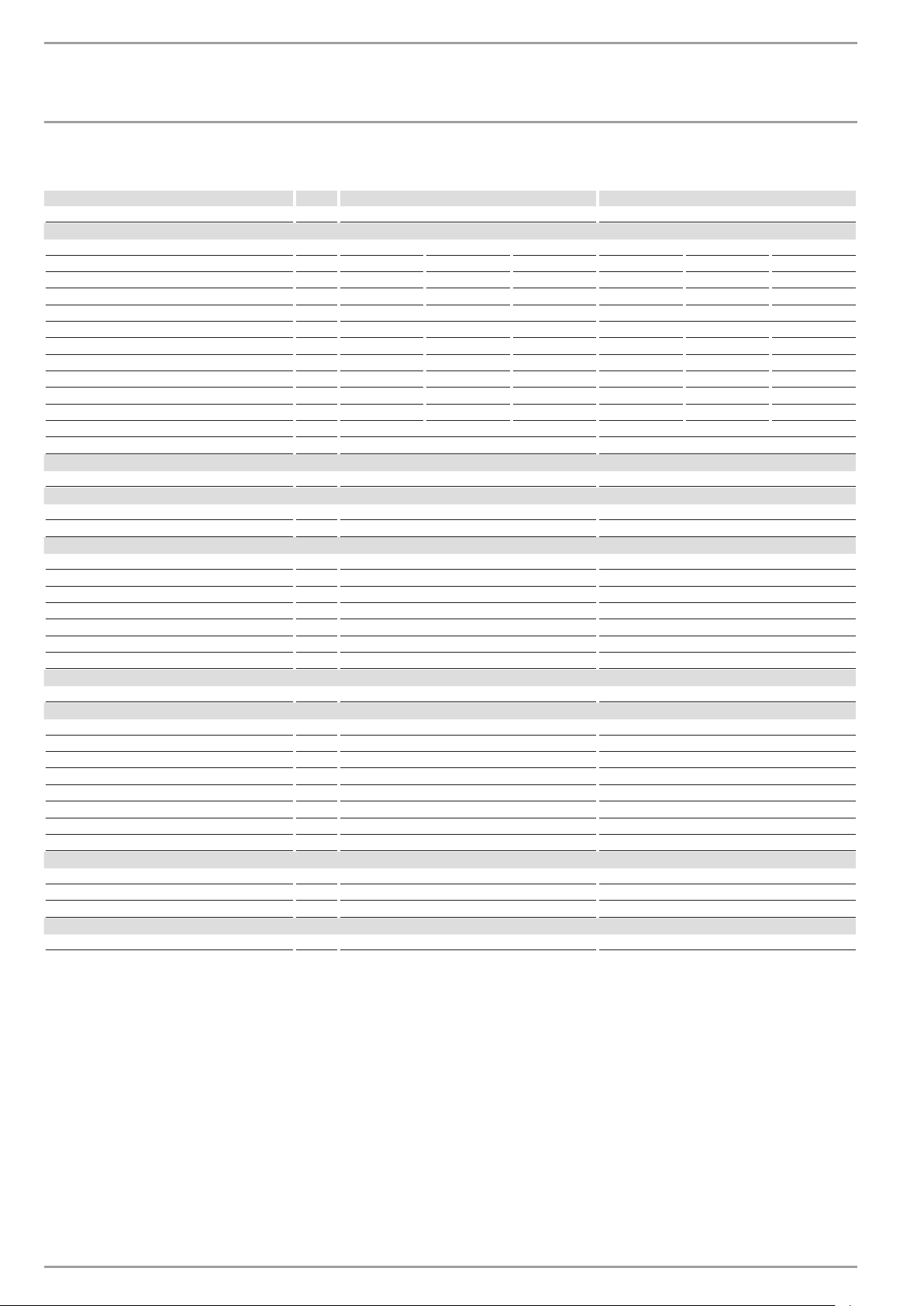
15.3 DHW output
DHW output is subject to the mains voltage, the appliance's con-
nected load and the cold water inlet temperature. The rated volt-
age and rated output can be found on the type plate (see chapter
"Troubleshooting").
Connected load in kW 38 °C DHW output in l/min.
Rated voltage Cold water inlet temperature
380 V 400 V 415 V 5°C 10°C 15°C 20°C
10.1 4.4 5.2 6.3 8.0
11.0 4.8 5.6 6.8 8.7
12.0 5.2 6.1 7.5 9.5
12.2 5.3 6.2 7.6 9.7
13.2 5.7 6.7 8.2 10.5
13.5 5.8 6.9 8.4 10.7
13.6 5.9 6.9 8.4 10.8
14.2 6.1 7.2 8.8 11.3
14.5 6.3 7.4 9.0 11.5
15.0 6.5 7.7 9.3 11.9
16.2 16.2 7.0 8.3 10.1 12.9
16.3 7.1 8.3 10.1 12.9
18.0 7.8 9.2 11.2 14.3
19.0 8.2 9.7 11.8 15.1
19.4 8.4 9.9 12.0 15.4
21.0 9.1 10.7 13.0 16.7
21.7 9.4 11.1 13.5 17.2
22.6 9.8 11.5 14.0 17.9
23.5 10.2 12.0 14.6 18.7
24.0 10.4 12.2 14.9 19.0
24.4 10.6 12.4 15.2 19.4
25.8 11.2 13.2 16.0 20.5
26.0 11.3 13.3 16.1 20.6
27.0 11.7 13.8 16.8 21.4
28.0 12.1 14.3 17.4 22.2
29.1 12.6 14.8 18.1 23.1
Connected load in kW 50 °C DHW output in l/min.
Rated voltage Cold water inlet temperature
380 V 400 V 415 V 5°C 10°C 15°C 20°C
10.1 3.2 3.6 4.1 4.8
11.0 3.5 3.9 4.5 5.2
12.0 3.8 4.3 4.9 5.7
12.2 3.9 4.4 5.0 5.8
13.2 4.2 4.7 5.4 6.3
13.5 4.3 4.8 5.5 6.4
13.6 4.3 4.9 5.6 6.5
14.2 4.5 5.1 5.8 6.8
14.5 4.6 5.2 5.9 6.9
15.0 4.8 5.4 6.1 7.1
16.2 16.2 5.1 5.8 6.6 7.7
16.3 5.2 5.8 6.7 7.8
18.0 5.7 6.4 7.3 8.6
19.0 6.0 6.8 7.8 9.0
19.4 6.2 6.9 7.9 9.2
21.0 6.7 7.5 8.6 10.0
21.7 6.9 7.8 8.9 10.3
22.6 7.2 8.1 9.2 10.8
23.5 7.5 8.4 9.6 11.2
24.0 7.6 8.6 9.8 11.4
24.4 7.7 8.7 10.0 11.6
25.8 8.2 9.2 10.5 12.3
26.0 8.3 9.3 10.6 12.4
27.0 8.6 9.6 11.0 12.9
28.0 8.9 10.0 11.4 13.3
29.1 9.2 10.4 11.9 13.9
15.4 Application areas/ conversion table
Specific electrical resistance and specific electrical conductivity
(see chapter "Data table").
Standard specifi-
cation
at 15 °C
20°C
25°C
Resist-
ance ρ
Conductivity σ Resist-
ance ρ
Conductivity σ Resist-
ance ρ
Conductivity σ
Ωcm mS/m μS/cm Ωcm mS/m μS/cm Ωcm mS/m μS/cm
900 111 1111 800 125 1250 735 136 1361
1000 100 1000 890 112 1124 815 123 1227
1100 91 909 970 103 1031 895 112 1117
1200 83 833 1070 93 935 985 102 1015
1300 77 769 1175 85 851 1072 93 933
15.5 Pressure drop
Taps/valves
Pressure drop at taps at flow rate of 10 l/min
Mono lever mixer tap, approx. MPa 0.04 - 0.08
Thermostatic valve, approx. MPa 0.03 - 0.05
Hand shower, approx. MPa 0.03 - 0.15
Sizing the pipework
To calculate pipework sizing, apply a pressure drop of 0.1MPa to
the appliance.
15.6 Fault conditions
In case of faults, loads up to 80°C at a pressure of 1.2MPa can
occur temporarily in the installation.
18 | DEL AU www.stiebel-eltron.com
INSTALLATION
Specication
15.7 Data table
DEL 18 AU DEL 27 AU
233741 233742
Electrical data
Rated voltage V 380 400 415 380 400 415
Rated output kW 16.2 18 19.4 23.5 26 28
Rated current A 24.7 26 27 35.6 37.7 38.9
Fuse/MCB rating A 25 25 32 35 40 40
Phases 3/PE 3/PE
Frequency Hz 50/60 50/60 50/- 50/- 50/- 50/-
Specific resistance ρ
15
≥ (at ϑcold ≤25°C) Ω cm 900 900 1000 900 900 1000
Specific conductivity σ
15
≤ (at ϑcold ≤25°C) μS/cm 1111 1111 1000 1111 1111 1000
Specific resistance ρ
15
≥ (at ϑcold ≤45°C) Ω cm 1200 1200 1300 1200 1200 1300
Specific conductivity σ
15
≤ (at ϑcold ≤45°C) μS/cm 833 833 770 833 833 770
Max. mains impedance at 50Hz Ω 0.474 0.450 0.433 0.316 0.3 0.289
Max. mains impedance at 380V / 60Hz Ω 0.392
Max. mains impedance at 400V / 60Hz Ω 0.372
Connections
Water connection G 1/2 A G 1/2 A
Application limits
Max. permissible pressure MPa 1.0 1.0
Max. inlet temperature for reheating °C 45 45
Values
Max. permissible inlet temperature °C 65 65
On l/min >2.5 >2.5
Flow rate for pressure drop l/min 5.2 7.7
Pressure drop at flow rate MPa 0.08 (0.06 without DMB) 0.16 (0.12 without DMB)
Flow rate limit at l/min 12 (7.5) 12 (7.5)
DHW delivery l/min 9.9 at 415V 14.3 bei 415 V
Δϑ on delivery K 28 28
Hydraulic data
Nominal capacity l 0.4 0.4
Versions
Connected load options - -
Temperature setting °C 30-50 30-50
Safety category 1 1
Insulating block Plastic Plastic
Heating system Bare wire Bare wire
Cover and back panel Plastic Plastic
Colour white white
IP rating IP25 IP25
Dimensions
Height mm 478 478
Width mm 225 225
Depth mm 105 105
Weights
Weight kg 3.6 3.6

ENGLISH
www.stiebel-eltron.com DEL AU| 19
WARR$NTY | ENVIRONMENT AND RECYCLING
Warranty
The warranty conditions of our German companies do not
apply to appliances acquired outside of Germany. In countries
where our subsidiaries sell our products, it is increasingly the
case that warranties can only be issued by those subsidiaries.
Such warranties are only granted if the subsidiary has issued
its own terms of warranty. No other warranty will be granted.
We shall not provide any warranty for appliances acquired in
countries where we have no subsidiary to sell our products.
This will not aect warranties issued by any importers.
Environment and recycling
We would ask you to help protect the environment. After use,
dispose of the various materials in accordance with national
regulations.
Stiebel Eltron Warranty for Water Heaters – Models DELAU
Who gives the warranty
1. The warranty is given by Stiebel Eltron (Aust) Pty Ltd
(A.B.N. 82066271083) of Unit 4/8 Rocklea Drive, Port Mel-
bourne, Victoria, 3207 ("we", "us" or "our").
The warranty
2. This warranty applies to Stiebel Eltron Water Heaters –
Models DEL18AU and DEL27AU (the "unit") manufac-
tured after 1 March 2014.
3. Subject to the warranty exclusions we will repair or re-
place, at our absolute discretion, a faulty component in
your unit free of charge if it fails to operate in accordance
with its specifications during the warranty period.
4. If we repair or replace a faulty component to your unit
under this warranty, the warranty period is not extended
from the time of the repair or replacement.
5. The warranty period commences on the date of completion
of the installation of the unit. Where the date of completion
of installation is not known, then the warranty period will
commence 2 months after the date of manufacture.
6. The warranty period for a unit used for domestic purposes
is shown in the table below. Domestic purposes means
that the unit is used in a domestic dwelling.
Component Warranty period
All components 5 years from the date of completion of the installa-
tion of the unit.
7. The warranty period for a unit used for commercial pur-
poses is shown in the table below. Commercial purposes
means that the unit is used for a non-domestic purpose
and includes but is not limited to being used in a motel,
hotel, mining camp or nursing home.
Component Warranty period
All components 1 year from the date of completion of the installa-
tion of the unit.
Your entitlement to make a warranty claim
8. You are entitled to make a warranty claim if:
8.1. you own the unit or if you have the owner's consent to rep-
resent the owner of the unit;
8.2. you contact us within a reasonable time of discovering the
problem with the unit; How you make a warranty claim
9. To make a warranty claim you must provide us with the
following information:
9.1. The model number of the unit;
9.2. A description of the problem with the unit;
9.3. The name, address and contact details (such as phone
number and e-mail address) of the owner;
9.4. The address where the unit is installed and the location
(e.g. in laundry);
9.5. The serial number of the unit;
9.6. The date of purchase of the unit and the name of the seller
of the unit;
9.7. The date of installation of the unit;
9.8. A copy of the certificate of compliance when the unit was
installed.
10. The contact details for you to make your warranty claim
are:
Name:
Stiebel Eltron (Aust) Pty Ltd
Address:
Unit 4, 8 Rocklea Drive, Port Melbourne, Victo-
ria, 3207
Telephone:
1800 153 351 (8.00am to 5.00pm AEST
Monday to Friday)
Contact person:
Customer Service Representative
E-mail:
service@stiebel.com.au
Warranty exclusions
12. We may reject your warranty claim if:
12.1. The unit was not installed by registered and qualified
tradespeople.
12.2. The unit was not installed and commissioned:
a) in Australia;
b) in accordance with the Operating and Installation
Guide; and
c) in accordance with the relevant statutory and local
requirements of the State or Territory in which the unit
is installed.

20 | DEL AU www.stiebel-eltron.com
WARR$NTY | ENVIRONMENT AND RECYCLING
12.3. The unit has not been operated or maintained in accord-
ance with the Operating and Installation Guide.
12.4. The unit does not bear its original Serial Number or Rating
Label.
12.5. The unit was damaged by any or any combination of the
following:
a) normal fair wear and tear;
b) connection to an incorrect water supply;
c) connection to water from a bore, dam or swimming
pool;
d) connection to an incorrect power supply;
e) connection to faulty equipment, such as damaged
valves;
f) foreign matter in the water supply, such as sludge or
sediment;
g) corrosive elements in the water supply;
h) accidental damage;
i) act of God, including damage by flood, storm, fire,
lightning strike and the like;
j) excessive water pressure, negative water pressure (par-
tial vacuum) or water pressure pulsation.
12.6. The unit was damaged before it was installed e.g. it was
damaged in transit.
12.7. An unauthorised person has modified, serviced, repaired
or attempted to repair the unit without our consent.
12.8. Non genuine parts other than those manufactured or ap-
proved by us have been used on the unit.
13. We may charge you:
13.1. for any additional transport costs if the unit is installed
more than 30 kilometres from our closest authorised ser-
vice technician.
13.2. for the extra time it takes our authorised service technician
to access the unit for inspection and testing if it is not sited
in accordance with the Operating and Installation Guide
and not readily accessible for inspection.
13.3. for any extra costs of our authorised service technician to
make the unit safe for inspection.
14. You must ensure that access to the unit by our authorised
service technician is safe and free from obstruction.
15. Our authorised service technician may refuse to inspect
and test the unit until you provide safe and free access to
it, at your own cost.
16. If we reject your warranty claim in accordance with clause
12, we may charge you for our authorised service techni-
cian's labour costs to inspect and test the unit.
17. In order to properly test the unit we may remove it to an-
other location for testing.
Australian Consumer Law
18. Our goods come with guarantees that cannot be excluded
under the Australian Consumer Law. You are entitled to a
replacement or refund for a major failure and compensa-
tion for any other reasonably foreseeable loss or damage.
You are also entitled to have the goods repaired or re-
placed if the goods fail to be of acceptable quality and the
failure does not amount to a major failure.
19. The Stiebel Eltron warranty for the unit is in addition to any
rights and remedies you may have under the Australian
Consumer Law.

ENGLISH
www.stiebel-eltron.com DEL AU| 21
NOTES

22 | DEL AU www.stiebel-eltron.com
NOTES

ENGLISH
www.stiebel-eltron.com DEL AU| 23
NOTES

Deutschland
STIEBEL ELTRON GmbH & Co. KG
Dr.-Stiebel-Straße 33 | 37603 Holzminden
Tel. 05531 702-0 | Fax 05531 702-480
www.stiebel-eltron.de
Verkauf Tel. 05531 702-110 | Fax 05531 702-95108 | [email protected]
Kundendienst Tel. 05531 702-111 | Fax 05531 702-95890 | [email protected]
Ersatzteilverkauf Tel. 05531 702-120 | Fax 05531 702-95335 | ersat[email protected]
Irrtum und technische Änderungen vorbehalten! | Subject to errors and technical changes! | Sous réserve
d‘erreurs et de modifications techniques! | Onder voorbehoud van vergissingen en technische wijzigingen! |
Salvo error o modificación técnica! | Excepto erro ou alteração técnica | Zastrzeżone zmiany techniczne i
ewentualne błędy | Omyly a technické změny jsou vyhrazeny! | A muszaki változtatások és tévedések jogát
fenntartjuk! |
Отсутствие ошибок не гарантируется. Возможны технические изменения.
| Chyby a
technické zmeny sú vyhradené! Stand 8870
Australia
STIEBEL ELTRON Australia Pty. Ltd.
6 Prohasky Street | Port Melbourne VIC 3207
Tel. 03 9645-1833 | Fax 03 9645-4366
www.stiebel.com.au
Austria
STIEBEL ELTRON Ges.m.b.H.
Eferdinger Str. 73 | 4600 Wels
Tel. 07242 47367-0 | Fax 07242 47367-42
www.stiebel-eltron.at
Belgium
STIEBEL ELTRON bvba/sprl
't Hofveld 6 - D1 | 1702 Groot-Bijgaarden
Tel. 02 42322-22 | Fax 02 42322-12
www.stiebel-eltron.be
China
Stiebel Eltron (Guangzhou) Technology
Development Co., Ltd.
Rm 102, F1, Yingbin-Yihao Mansion, No. 1
Yingbin Road
Panyu District | 511431 Guangzhou
Tel. 020 61952996 | Fax 020 61952990
www.stiebeleltron.cn
Czech Republic
STIEBEL ELTRON spol. s r.o.
K Hájům 946 | 155 00 Praha 5 - Stodůlky
Tel. 251116-111 | Fax 235512-122
www.stiebel-eltron.cz
Denmark
Pettinaroli A/S
Mandal Allé 21 | 5500 Middelfart
Tel. 06341 666-6 | Fax 06341 666-0
www.stiebel-eltron.dk
Finland
STIEBEL ELTRON OY
Kapinakuja 1 | 04600 Mäntsälä
Tel. 020 720-9988
www.stiebel-eltron.fi
France
STIEBEL ELTRON SAS
7-9, rue des Selliers
B.P 85107 | 57073 Metz-Cédex 3
Tel. 0387 7438-88 | Fax 0387 7468-26
www.stiebel-eltron.fr
Hungary
STIEBEL ELTRON Kft.
Gyár u. 2 | 2040 Budaörs
Tel. 01 250-6055 | Fax 01 368-8097
www.stiebel-eltron.hu
Japan
NIHON STIEBEL Co. Ltd.
Kowa Kawasaki Nishiguchi Building 8F
66-2 Horikawa-Cho
Saiwai-Ku | 212-0013 Kawasaki
Tel. 044 540-3200 | Fax 044 540-3210
www.nihonstiebel.co.jp
Netherlands
STIEBEL ELTRON Nederland B.V.
Daviottenweg 36 | 5222 BH 's-Hertogenbosch
Tel. 073 623-0000 | Fax 073 623-1141
www.stiebel-eltron.nl
Poland
STIEBEL ELTRON Polska Sp. z o.o.
ul. Działkowa 2 | 02-234 Warszawa
Tel. 022 60920-30 | Fax 022 60920-29
www.stiebel-eltron.pl
Russia
STIEBEL ELTRON LLC RUSSIA
Urzhumskaya street 4,
building 2 | 129343 Moscow
Tel. 0495 7753889 | Fax 0495 7753887
www.stiebel-eltron.ru
Slovakia
TATRAMAT - ohrievače vody, s.r.o.
Hlavná 1 | 058 01 Poprad
Tel. 052 7127-125 | Fax 052 7127-148
www.stiebel-eltron.sk
Switzerland
STIEBEL ELTRON AG
Industrie West
Gass 8 | 5242 Lupfig
Tel. 056 4640-500 | Fax 056 4640-501
www.stiebel-eltron.ch
Thailand
STIEBEL ELTRON Asia Ltd.
469 Moo 2 Tambol Klong-Jik
Amphur Bangpa-In | 13160 Ayutthaya
Tel. 035 220088 | Fax 035 221188
www.stiebeleltronasia.com
United Kingdom and Ireland
STIEBEL ELTRON UK Ltd.
Unit 12 Stadium Court
Stadium Road | CH62 3RP Bromborough
Tel. 0151 346-2300 | Fax 0151 334-2913
www.stiebel-eltron.co.uk
United States of America
STIEBEL ELTRON, Inc.
17 West Street | 01088 West Hatfield MA
Tel. 0413 247-3380 | Fax 0413 247-3369
www.stiebel-eltron-usa.com
A 313148-37836-8944
B 313881-37836-8943
4<AMHCMO=bdbeij>