Loading ...
USE THE FOLLOWING INSTRUCTIONS
IN PLACE OF STEPS #1 THRU #46 IN THE
SNOW THROWER MANUAL.
PARTS SHOWN IN GRAY ARE SUPPLIED WITH THE KIT.
Right hand (R.H.) and left hand (L.H.) are determined
from the operators position while seated on the tractor.
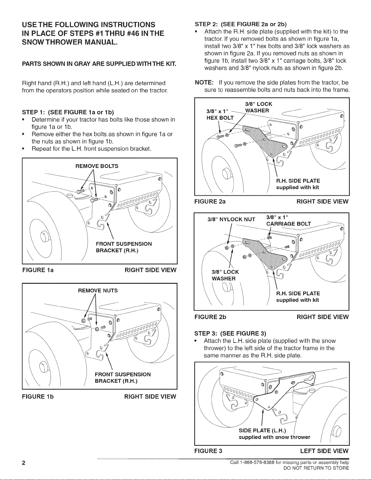
STEP 1: (SEE FIGURE la or lb)
• Determine if your tractor has bolts like those shown in
figure la or lb.
Remove either the hex bolts as shown in figure la or
the nuts as shown in figure lb.
Repeat for the L.H. front suspension bracket.
REMOVE BOLTS
\
FRONT SUSPENSION
BRACKET (R.H.)
FIGURE la RIGHT SIDE VIEW
REMOVE NUTS
\
FRONT SUSPENSION
BRACKET (R.H.)
FIGURE lb RIGHT SIDE VIEW
STEP 2: (SEE FIGURE 2a or 2b)
Attach the R.H. side plate (supplied with the kit) to the
tractor. If you removed bolts as shown in figure la,
install two 3/8" x 1" hex bolts and 3/8" lock washers as
shown in figure 2a. If you removed nuts as shown in
figure lb, install two 3/8" x 1" carriage bolts, 3/8" lock
washers and 3/8" nylock nuts as shown in figure 2b.
NOTE: If you remove the side plates from the tractor, be
sure to reassemble bolts and nuts back into the frame.
318" × 1"
HEX BOLT
3/8" LOCK
WASHER
R.H. SiDE PLATE
supplied with kit
FIGURE 2a RIGHT SIDE VIEW
3/8" NYLOCK NUT 3/8" x1"
CARRIAGE BOLT
3/8" LOCK
WASHER
R.H. SiDE PLATE
supplied with kit
FIGURE 2b RIGHT SIDE VIEW
STEP 3" (SEE FIGURE 3)
Attach the L.H. side plate (supplied with the snow
thrower) to the left side of the tractor frame in the
same manner as the R.H. side plate.
SiDE PLATE (L.H.)
supplied with snow thrower
FIGURE 3 LEFT SiDE VIEW
2 Call 1-866-578-8388 for missing parts or assembly help
DO NOT RETURN TO STORE
Loading ...
Loading ...
Loading ...