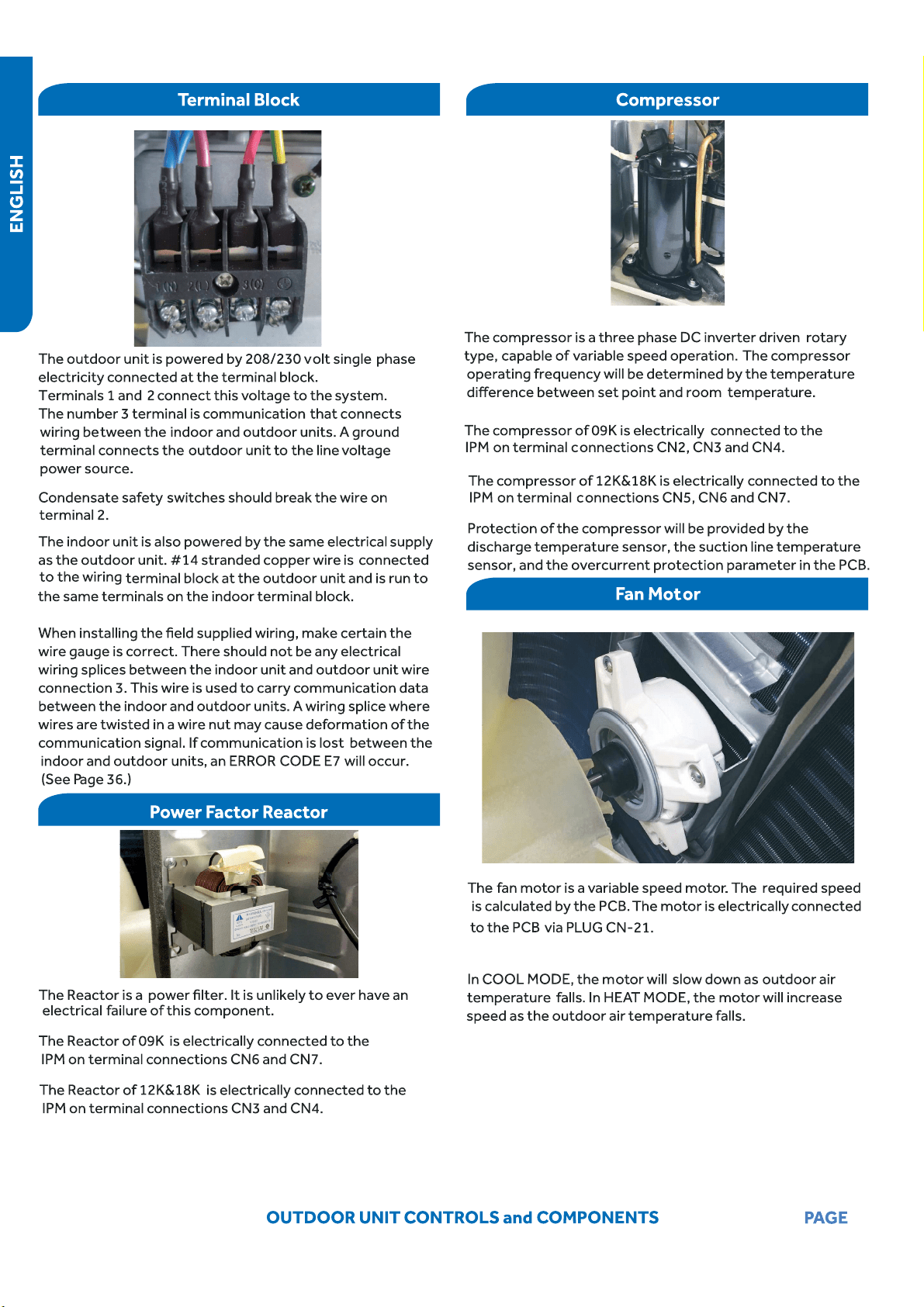
3
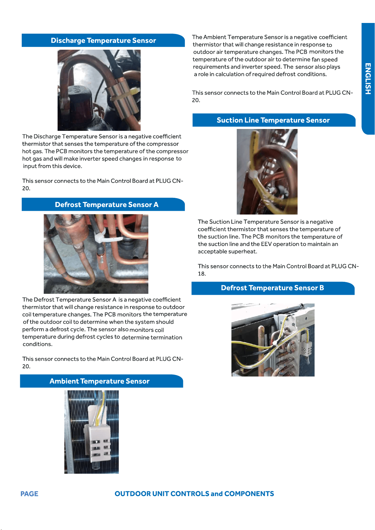
7
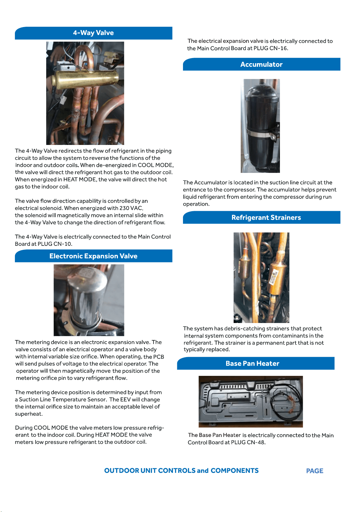
10
20
28
38
52
62
75
104

[This page intentionally left blank.]
INTRODUCTION
PAGE 3
Introduction
Safety Precautions .............................................................................................................................................................4
Warnings and Cautions ......................................................................................................................................................................4
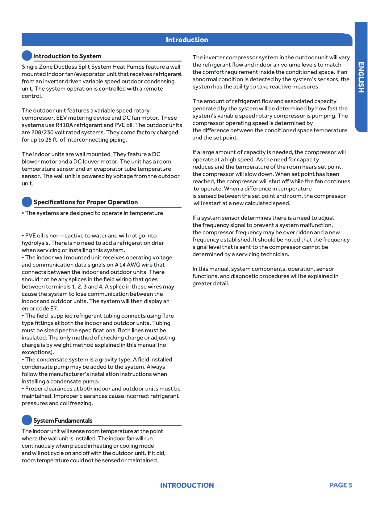
Introduction to System ......................................................................................................................................................5
................................................................................................................5
System Fundamentals........................................................................................................................................................................5
Table of Contents
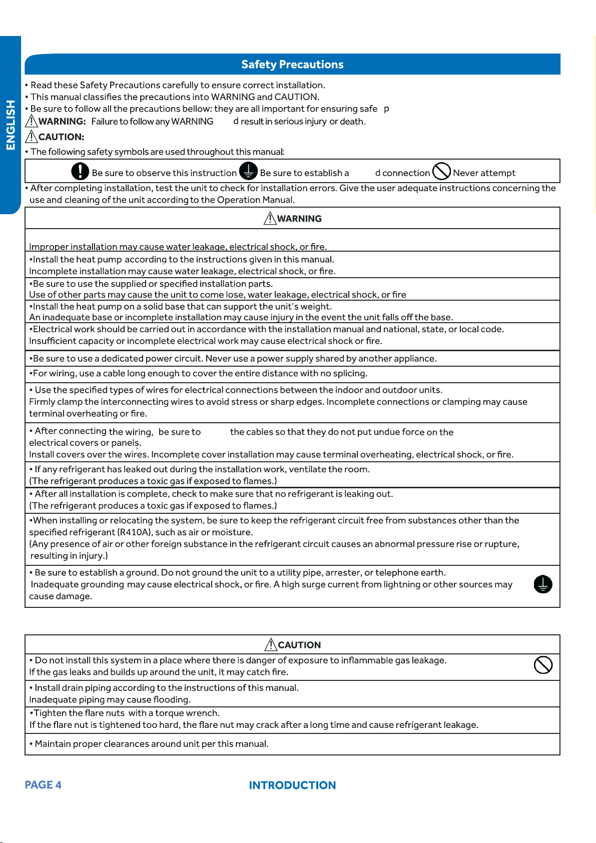
Failure to follow any CAUTION may in some cases result in grave consequences.
coul
o
eration.
groun
route
The indoor unit can be set from 60°F-86°F (16°C-30°C)
during both cooling and heating.
PAGE 6
PAGE 7
SYSTEM SPECIFICATIONS
System
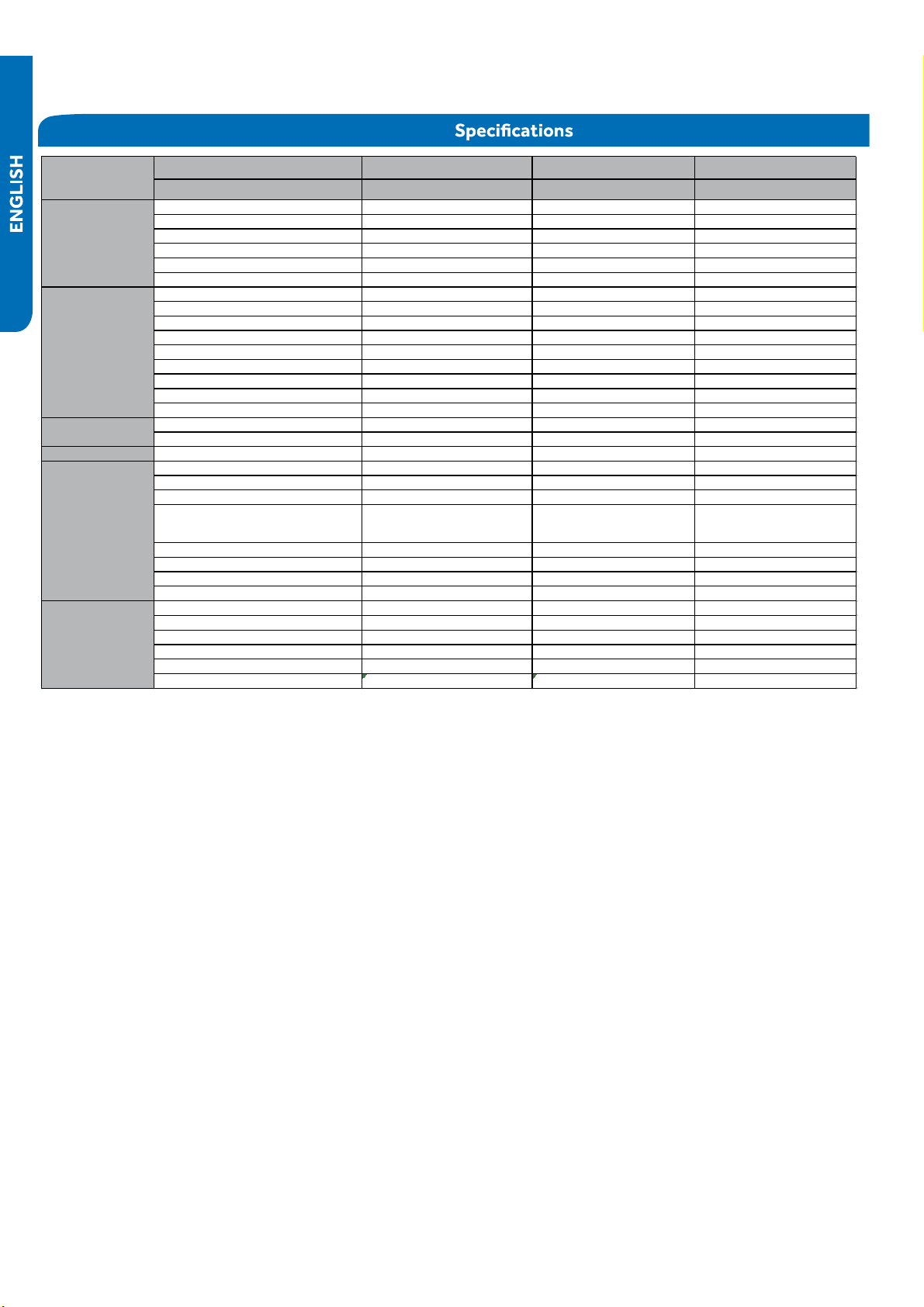
Outdoor 1U09EH2VHE/ASH109URDSE 1U12EH2VHE/ASH112URDSE 1U18EH2VHE/ASH118URDSE
Indoor AW09EH2VHD/ASYW09URDWD AW12EH2VHD/ASYW12URDWD AW18EH2VHD/ASYW18URDWD
Rated Capacity Btu/hr 9,000 12,000 18,000
Capacity Range
●
Btu/hr 3100~12000 3100~15000 8,500~21000
Rated Power Input W 560 800 1,385
SEER 30 27 23
EER 16.0 15.0 13.0
Moisture Removal Pt./h 0.60 1.60 3.80
Rated Heating Capacity 47°F Btu/hr 10,000 14,500 20,000
Heating Capacity Range Btu/hr 3100~20000 3100~22000 8700-27000
Rated Power Input W 845 1,400 1,920
HSPF 15.2 13.0 12.0
Max. Heating Capacity 5°F Btu/hr 12,000 17,000 25,000
Max. Heating Capacity -4°F Btu/hr 10,500 15,500 22,000
Max. Heating Capacity -15°F Btu/hr 8,600 14,500 20,000
Max. Heating Capacity -22°F Btu/hr 7,400 12,400 17,200
Max. Heating Capacity -31°F Btu/hr 3,200 5,400 7,400
Cooling °F(°C) 14~115(-10~46) 14~115(-10~46) 14~115(-10~46)
Heating °F(°C) -31~75(-35~24) -31~75(-35~24) -31~75(-35~24)
Power Supply Voltage, Cycle, Phase V/Hz/- 208-230/60/1 208-230/60/1 208-230/60/1
Compressor Type DC Inverter Rotary DC Inverter Rotary DC Inverter Rotary
Maximum Fuse Size A 15 20 30
Minimum Circuit Amp A 13 14 20
Outdoor Noise Level dB 55 55 51
Dimension: Height in (mm) 27 1/2(697) 27 1/2(697) 30(762)
Dimension: Width in (mm) 35(890) 35(890) 36 1/4(920)
Dimension: Depth in (mm) 13 7/8(353) 13 7/8(353) 15 1/8(385)
Weight (Ship/Net)- lbs (kg) 119.7/102.198.3 (54.3/46.3) 124.6/108 (56.5/49) 152.6/132.7 (69.2/60.2)
Connections Flare Flare Flare
Liquid O.D. in 1/4 1/4 1/4
Suction O.D. in 1/2 1/2 1/2
Factory Charge Oz 57.0 62.1 82.9
Maximum Line Length Ft / m 50/15 50/15 83/25
Maximum Height Ft / m 33/10 33/10 50/15
Model Name
Refrigerant Line
Cooling
Operating Range
Outdoor Unit
Heating

597/524/430/344/324
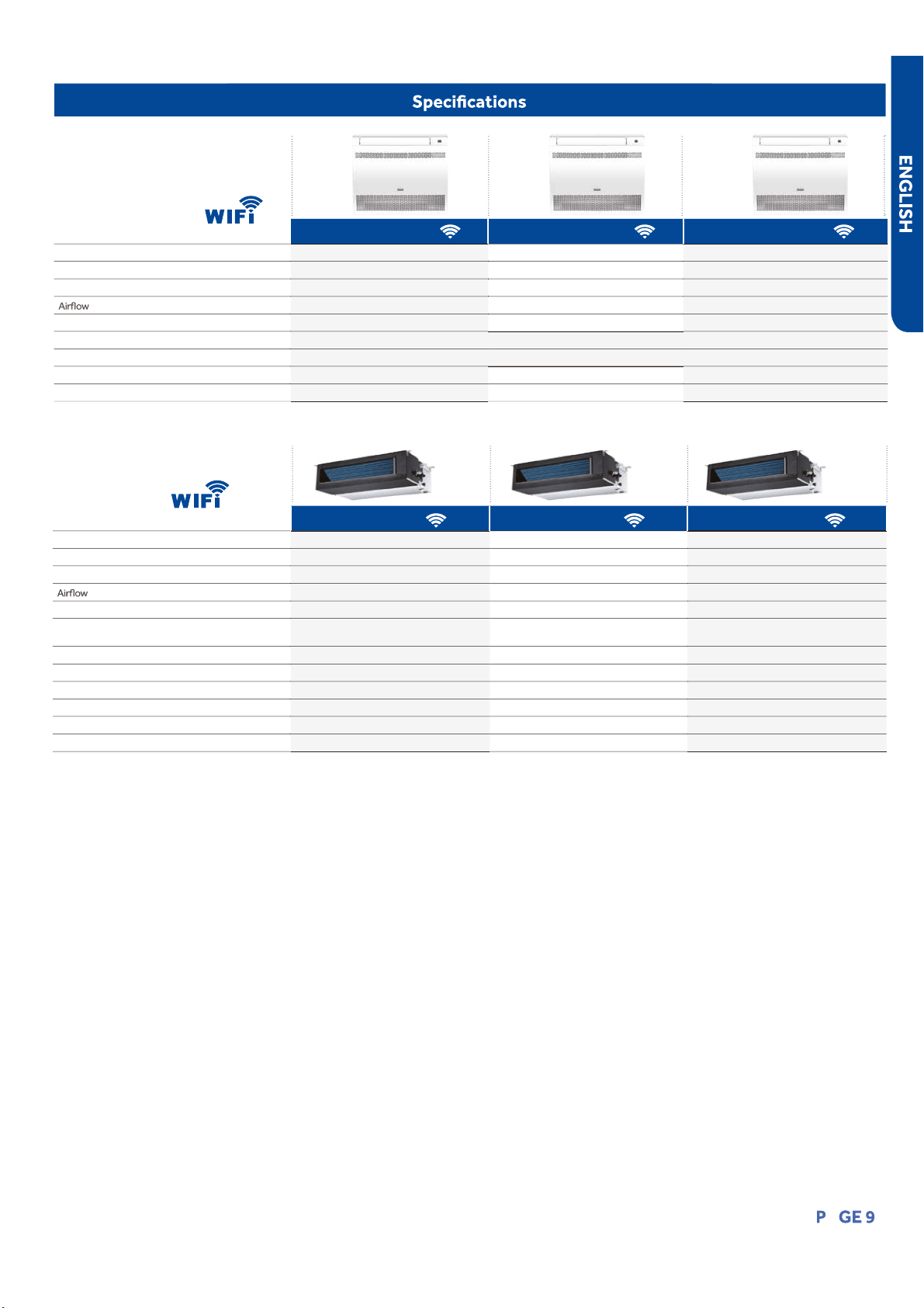
Airflow CFM
(Turbo/High/Med/Low/Quiet)
636/541/436/330/259583/383/324/264/240
AW09EH2VHD
AW12EH2VHD
AW18EH2VHD
Topic Title
INTRODUCTION
A
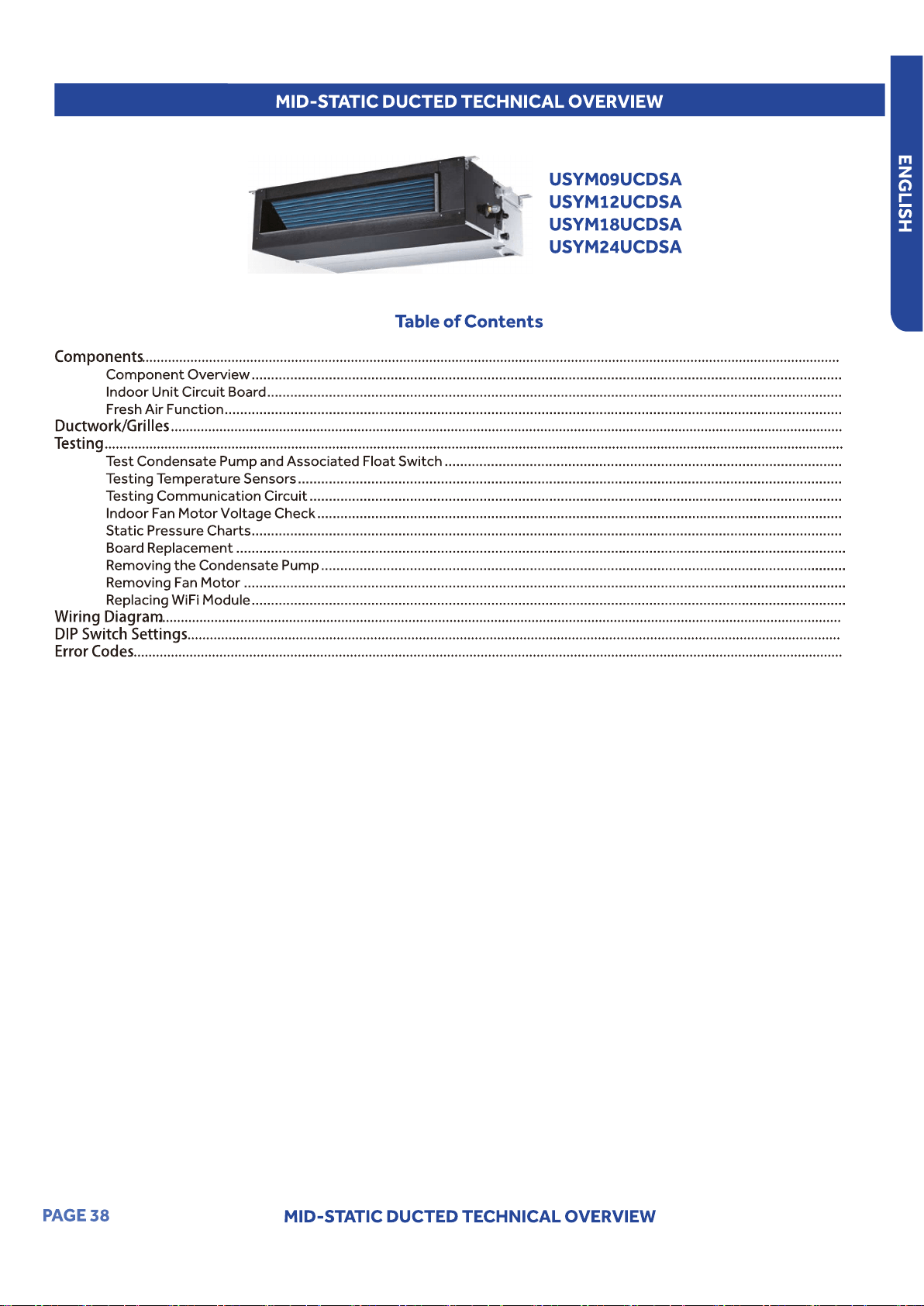
USYF09UCDWA
●
USYF12UCDWA USYF18UCDWA
Rated Cooling Capacity Btu/hr 9,000 12,000 15,000
Rated Heating Capacity Btu/h
●
r 10,000 13,000 18,000
Voltage, Cycle, Phase V/Hz/- 208-230/60/1 208-230/60/1 208-230/60/1
(Turbo/High/Med/Low/Quiet) CFM 264/235/205/176/147 294/264//205/176/147 341/311/282/252/223
Indoor Sound Level dB (Turbo/High/Med/Low/Quiet) 40/32/25/20 42/34/26/21 46/37/33/28
Chassis Dimension: HxWxD in (mm) 23.6/27.5/8.3 (600/700/210)
Weight (Ship/Net)- lbs (kg) 36/40 (16.5/18.5)
Liquid / Suction O.D. in 1/4 3/8 1/4 3/8 1/4 1/2
Drainpipe Size O.D. in 1 1/4 1 1/4 1 1/4
Built-in WiFi
Console Indoor
Mid-Static Ducted Indoor
USYM09UCDSA USYM12UCDSA USYM18UCDSA
Rated Cooling Capacity Btu/hr 9,000 12,000 18,000
Rated Heating Capacity Btu/hr 10,000 13,000 19,000
Voltage, Cycle, Phase V/Hz/- 208-230/60/1 208-230/60/1 208-230/60/1
(Turbo/High/Med/Low/Quiet) CFM 494/423/352/264 494/423/352/264 635/529/458/388
Max. External Static Pressure in.W.G (Pa) 0.6 (150) 0.6 (150) 0.6 (150)
Indoor Sound Level dB
(Turbo/High/Med/Low/Quiet)
35/32/29/26 35/32/29/26 37/34/32/29
Chassis Dimension: HxWxD in (mm) 27.
●
5/27.5/9.7(700/700/248) 27.5/27.5/9.7(700/700/248) 43.3/27.5/9.7(1100/700/248)
Weight (Ship/Net)- lbs (kg) 5
●
7/66(26/30) 57/66(26/30) 70/77 (32/35)
Liquid / Suction O.D. in 1/4
●
3/8 1/4 3/8 1/4 1/2
Drainpipe Size O.D. in 1 1/4 1 1/4 1 1/4
Condensate Pump Standard Standard Standard
Max. Drain-Lift height in(mm) 39(1000) 39(1000) 39(1000)
Built-in WiFi
OUTDOOR UNIT CONTROLS and COMPONENTS
PAGE
Outdoor Unit Controls and Components
Table of Contents
Outdoor Unit Introduction ................................................................................................................................................11
11
Outdoor Main Control Board ............................................................................................................................................12
Terminal Block .................................................................................................................................................................. 13
Reactor ............................................................................................................................................................................ 13
Compressor ..................................................................................................................................................................... 13
Outdoor Fan Motor ........................................................................................................................................................... 13
Discharge Temperature Sensor ........................................................................................................................................ 14
Defrost Temperature Sensor ............................................................................................................................................ 14
Outdoor Ambient Temperature Sensor ............................................................................................................................ 14
Suction Line
●
Temperature Sensor ..................................................................................................................................... 14
4-Way Valve ..................................................................................................................................................................... 15
Electronic Expansion Valve ............................................................................................................................................... 15
Accumulator .................................................................................................................................................................... 15
51......................................................................................................................................................................... sreniartS
Base Pan Heater................................................................................................................
●
............................................... 15
...................................................................................................................................
OUTDOOR UNIT CONTROLS and COMPONENTS
PAGE
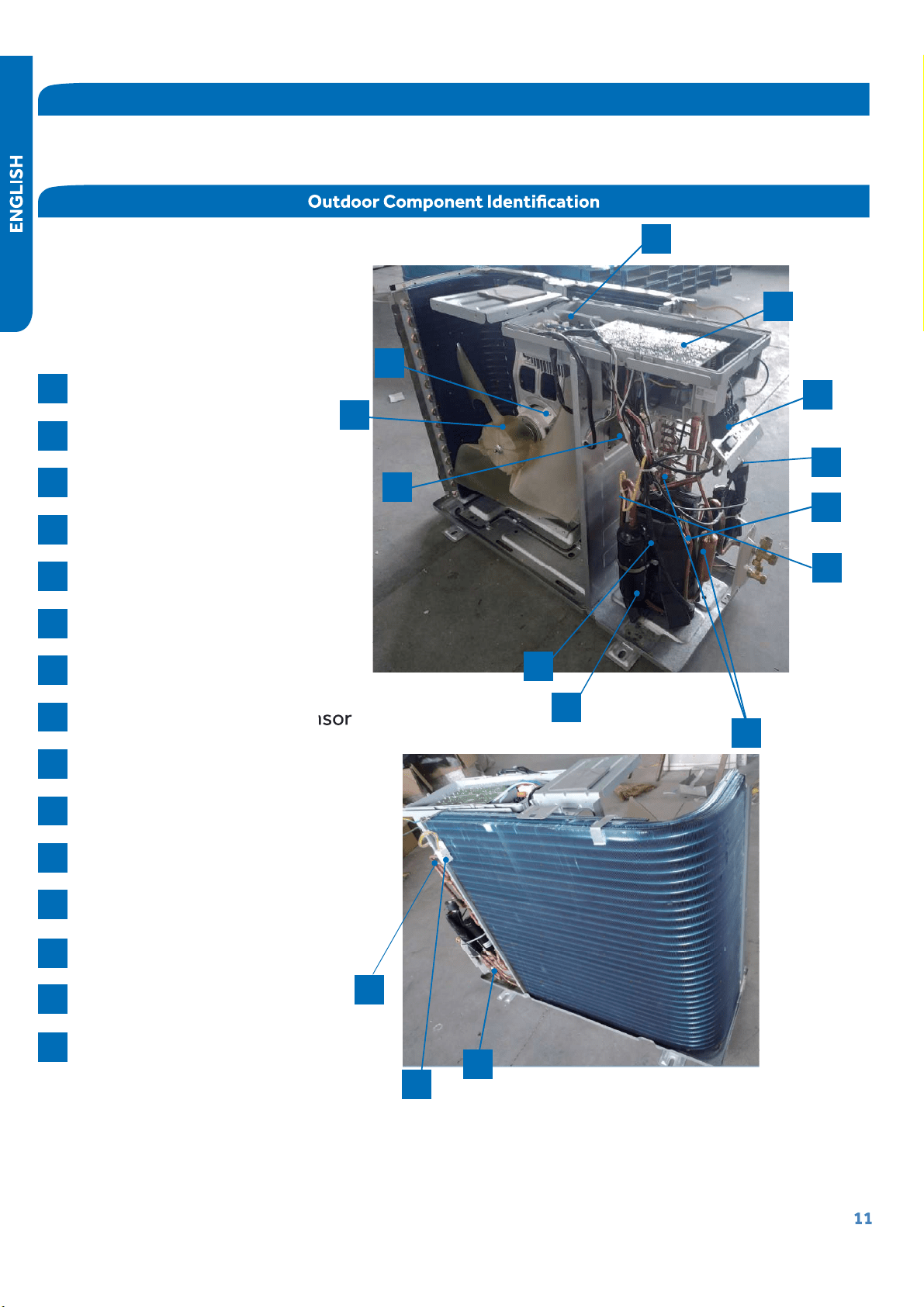
Outdoor Unit Introduction
The
outdoor
unit
has
two
circuit
boards,
an Inverter Power Module (IPM) that
drives
the
compressor and main control
board (PCB)
that
manages
system
functions
and
inverter
calculations.
Sensor
s
monitor
key
temperatures
throughout
the
system
to
manage
operational
decisions.
4-Way
Valve
Accumulat
or
Compressor
Defrost
Temperature
Sensor
Discharge
Temperature
Sensor
Electronic
Expansion
Valve
Refrigerant
Strainers
Ambient
Temperature
Sensor
Fan
Motor
Power
Factor
Reactor
Suction
Line
Temperature
Sensor
Terminal
Block
Main
Control
Board (PCB)
Module
Control
Board (IPM)
Fan
Blade
1
2
3
4
5
6
7
8
9
10
11
12
13
14
15
8
4
6
11
12
13
14
1
3
2
7
5
9
10
15
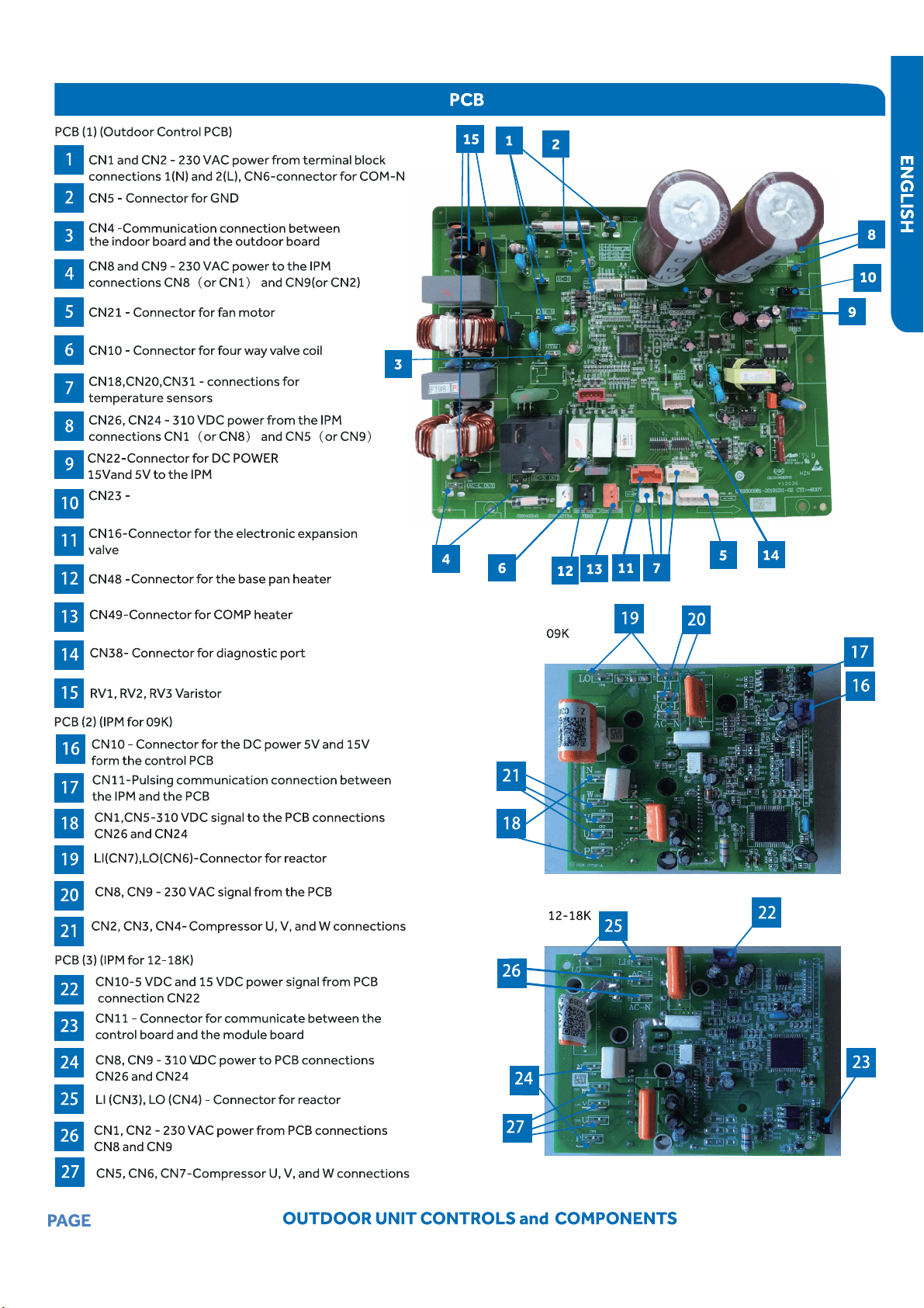
5VDC and 15VDC pulsing communication
connection between the PCB and the IPM
12
13
14
The Defrost Temperature Sensor B is same as the Defrost
Temperature Sensor A. The sestem chooses the lowest of the
two temoerature values.
This sensor connects to the Main Control Board at PLUG CN-31.
15
16
Piping diagrams
Pipingdiagrams
EEV
EEV
Discharge temp.sensor
Discharge temp.sensor
Suction temp.
sensor
Suction temp.
sensor
Indoor
ambient
temp.
sensor
Indoor
ambient
temp.
sensor
Outdoor
ambient
temp.
sensor
Outdoor
ambient
temp.
sensor
Defrost
sensor
Defrost
sensor
Indoor
heat
exchanger
temp.
sensor
Indoor
heat
exchanger
temp.
sensor
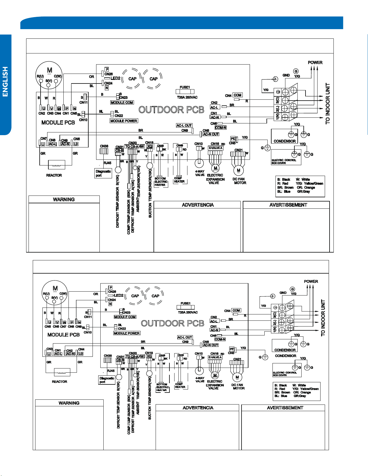
OUTDOOR UNIT WIRING DIAGRAM
COMPRESSOR
Electrical Shock Hazard
Capacitor retains charge aer
power is disconnected. Confirm
voltage at capacitor has dissipated
(<10V DC) with hand held voltmeter
before servicing. LED2 light
between CN24 and CN26 should be
off.
Riesgo de Descarga Eléctrica
El capacitor reene carga una vez
desconectada la corriente. Confirme que el
voltaje del capacitor se haya disipado (<10V
DC) apoyando la mano sobre el
volmetro
antes de realizar el servicio técnico. La luz
LED2 que se encuentra entre CN24 y CN26
deberá estar apagada.
Risque de choc électrique
Le condensateur conserve sa charge après la
coupure de l’alimentaon électrique. Avant
de procéder à une réparaon, vérifiez que le
courant au condensateur s’est dissipé
(<10 VCC) à l’aide d’un voltmètre manuel. Le
voyant LED2 entre CN24 et CN26 doit être
éteint.
0011509127
OUTDOOR UNIT WIRING DIAGRAM
COMPRESSOR
Electrical Shock Hazard
Capacitor retains charge aer
power is disconnected. Confirm
voltage at capacitor has dissipated
(<10V DC) with hand held voltmeter
before servicing. LED2 light
between CN24 and CN26 should be
off.
Riesgo de Descarga Eléctrica
El capacitor reene carga una vez
desconectada la corriente. Confirme que el
voltaje del capacitor se haya disipado (<10V
DC) apoyando la mano sobre el
volmetro
antes de realizar el servicio técnico. La luz
LED2 que se encuentra entre CN24 y CN26
deberá estar apagada.
Risque de choc électrique
Le condensateur conserve sa charge après la
coupure de l’alimentaon électrique. Avant
de procéder à une réparaon, vérifiez que le
courant au condensateur s’est dissipé
(<10 VCC) à l’aide d’un voltmètre manuel. Le
voyant LED2 entre CN24 et CN26 doit être
éteint.
0011509127A
PAGE 17
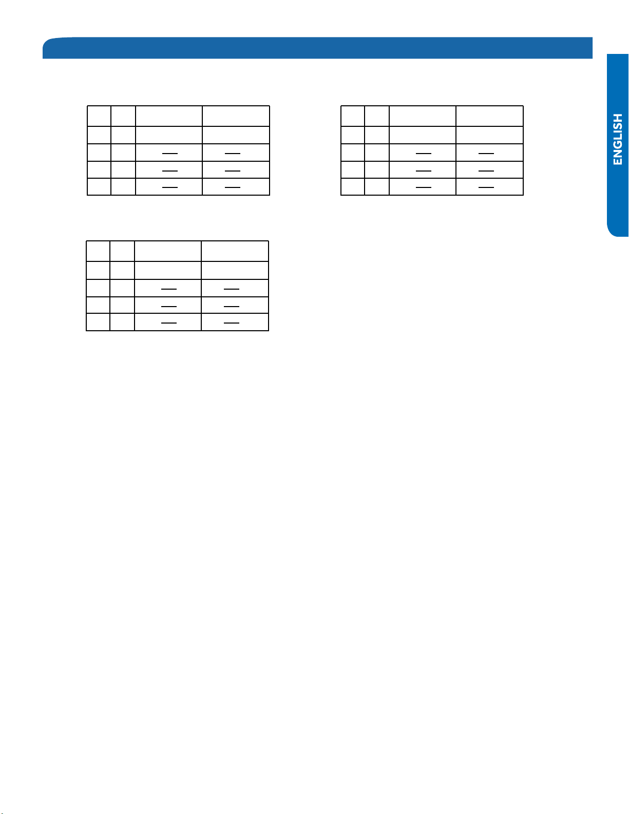
J1 J2 SW1-1 SW1-2
ON
ON
ON
OFF
OFF
OFF OFF
ON
OFF
OFF
J1 J2 SW1-1 SW1-2
ON
ON
ON
OFF
OFF
OFF OFF
ON
OFF
OFF
J1 J2 SW1-1 SW1-2
ON
ON
ON
OFF
OFF
OFF OFF
ON
OFF
OFF
1U09EH2VHE1
ASH109URDSE1
1U12EH2VHE1
ASH112URDSE1
1U18EH2VHE1
ASH118URDSE1
PAGE 18
ERROR CODES & PROBLEM SOLVING
PAGE 19
ENGLISH
Indoor Unit Display
Error codes will be display on the indoor unit in place of the set temperature.
Code Indication
Fault Description
Indoor Display panel code
indication
Outdoor
(LED1
flash
times)
Other
display
Indoor and
Outdoor
E7 15
Communication fault between indoor
and outdoor units
Indoor
Malfunction
E1 -- Room temperature sensor failure
E2 -- Heat-exchange sensor failure
E4
-- Indoor EEPROM error
E14 -- Indoor fan motor malfunction
Outdoor
Malfunction
F12 1 Outdoor EEPROM error
F1 2 The protection of IPM
F22 3
Overcurrent protection of AC
electricity for the outdoor model
F3 4
Communication fault between the IPM
and outdoor PCB
F19 6 Power voltage is too high or low
F4 8
Overheat protection for Discharge
temperature
F21 10 Defrost temperature sensor failure
F7 11 Suction temperature sensor failure
F6 12 Ambient temperature sensor failure
F25 13 Discharge temperature sensor failure
F11 18
deviate from the normal for the
compressor
F28 19 Loop of the station detect error
F2 24 Overcurrent of the compressor
F23 25
Overcurrent protection for single-phase
of the compressor
21
21
22
23
23
23
23
24
24
24
25
PAGE 20
PAGE 21
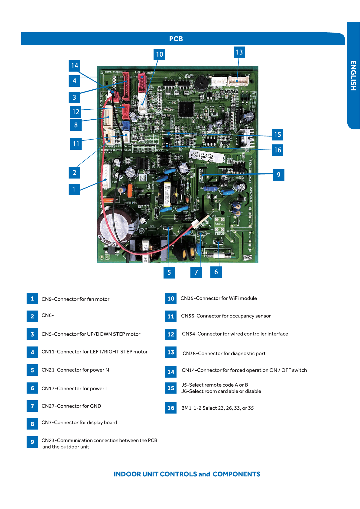
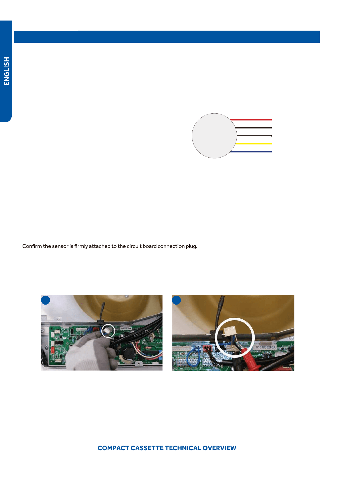
Connector for coil temperature sensor
●
and room temperature sensor
PAGE22
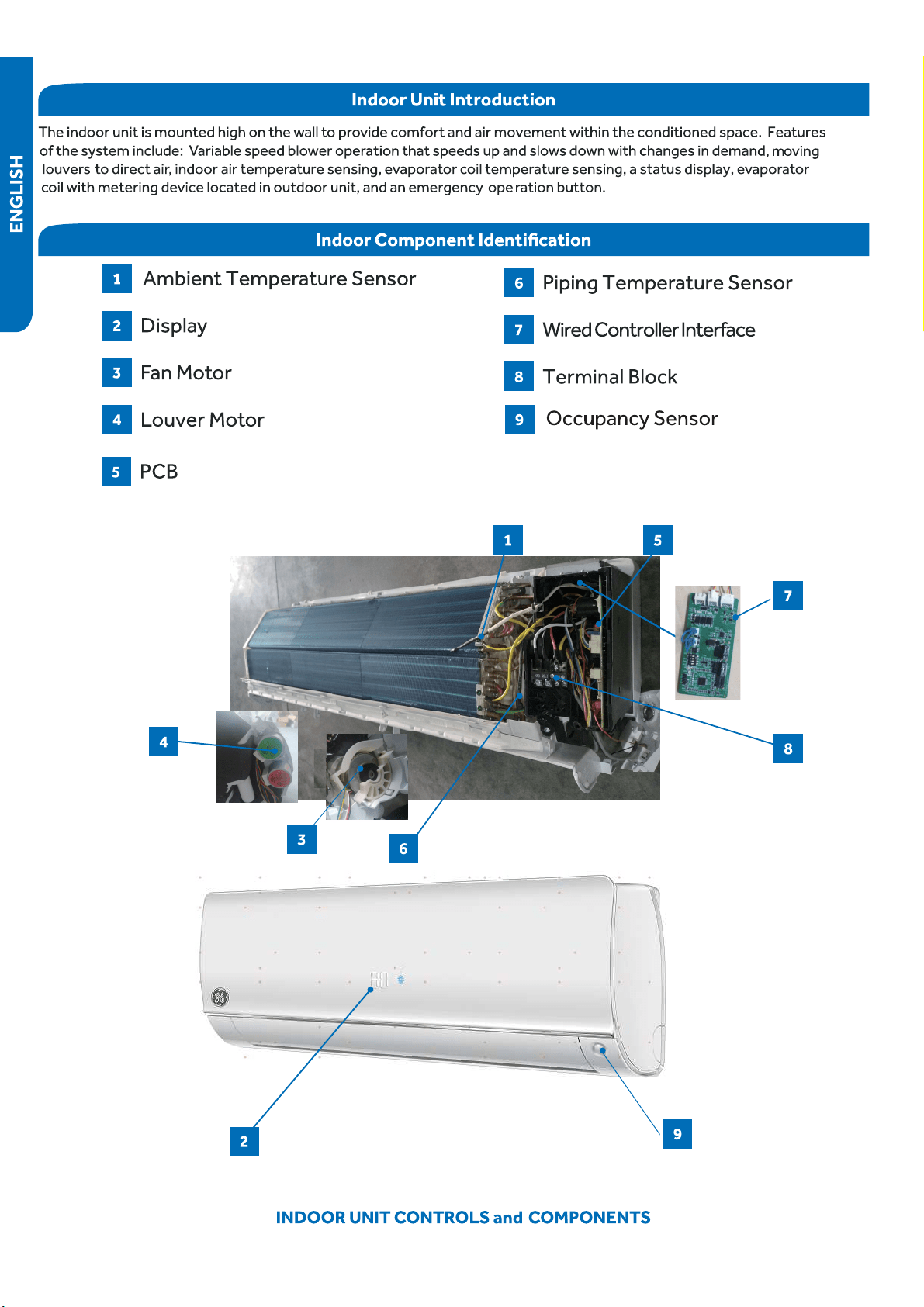
INDOOR UNIT CONTROLS and COMPONENTS
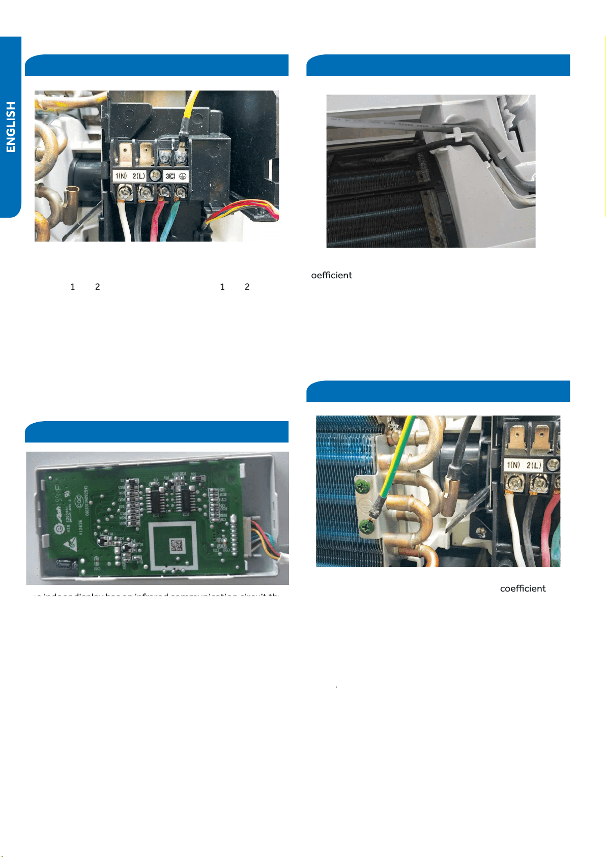
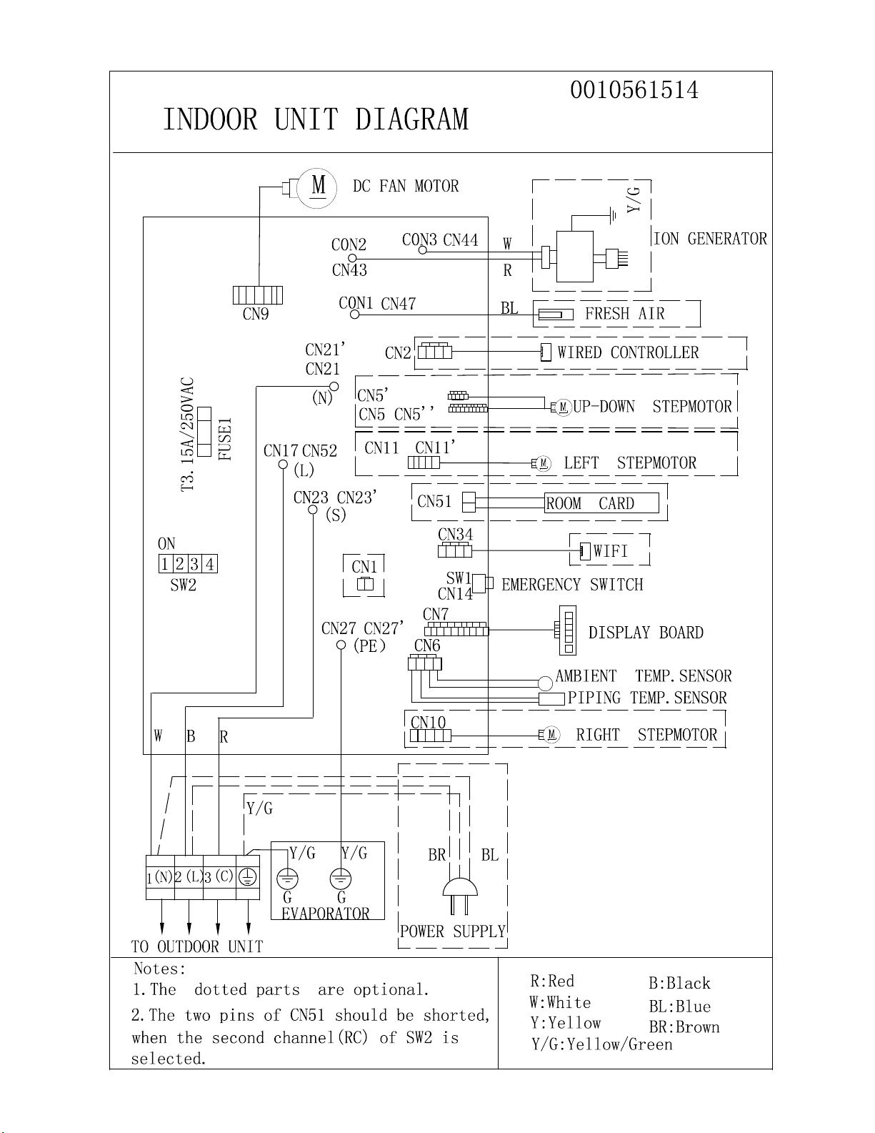
Terminal Block
Display
●
The
unit
terminal
block
receives
electrical
power
from the
outdoor
unit.
There
are
4
connections
for
electrical
wires.
Terminals
1
and
2
are
connected
to
terminals
1
and
2
of
the
outdoor
unit.
This
wiring
supplies
power
to
the
indoor
unit.
Terminal
3
is
a
communication
wire.
The
indoor
unit
sends
indoor
air
temperature,
coil
temperature
and
temperature
setpoint
information
to
the
outdoor
unit
on
this
wire.
If
a
splice
or
break
in
this
wire
is
present,
the
indoor
unit
will
not
be
able
to
communicate
with
the
outdoor
unit.
The
ERROR
C
ODE
will
be
an
E7.
The
indoor
display
has
an
infrared
communication
circuit
that
receives
operating
commands
from
the
remote
control.
This
displa
y
will
indicate
operating
modes,
error
codes,
indoor
air
temper
ature,
timer
status, and power status.
Ambient Temperature Sensor
The
Ambient (room) Temperature Sensor
is
a
negative
c
thermistor
that
will
decrease
in
resistance
with
increases
in
room
air
temperature.
The
sensor
is
located
on
a
clip
mounted
in the return air stream.
T
he
sensor
connects
to
the
control
board
at
Plug
CN-6.
Piping Temperature Sensor
The
Piping
Temperature
Sensor
is
a
negative
thermist
or
that
will
decrease
in
resistance
with
increases
in
c
oil
temperature.
The
sensor
is
located
in
a
socket
soldered
t
o the surface of the indoor coil.
This
sensor
will
monitor
the
temperature
of
the
indoor
coil
in
both
cooling
and
heating
modes
of
operation.
Should
abnormally
cold
or
hot
coil
temperature
be
detected
by
this
sensor
,
sensor
sensor
the
system
will
take
steps
to
c
orrect
the
condition
or
report
an
ERROR
CODE.
T
he
sensor
connects
to
the
control
board
at
Plug
CN-6.
PAGE 23
PAGE 24
INDOOR UNIT CONTROLS and COMPONENTS
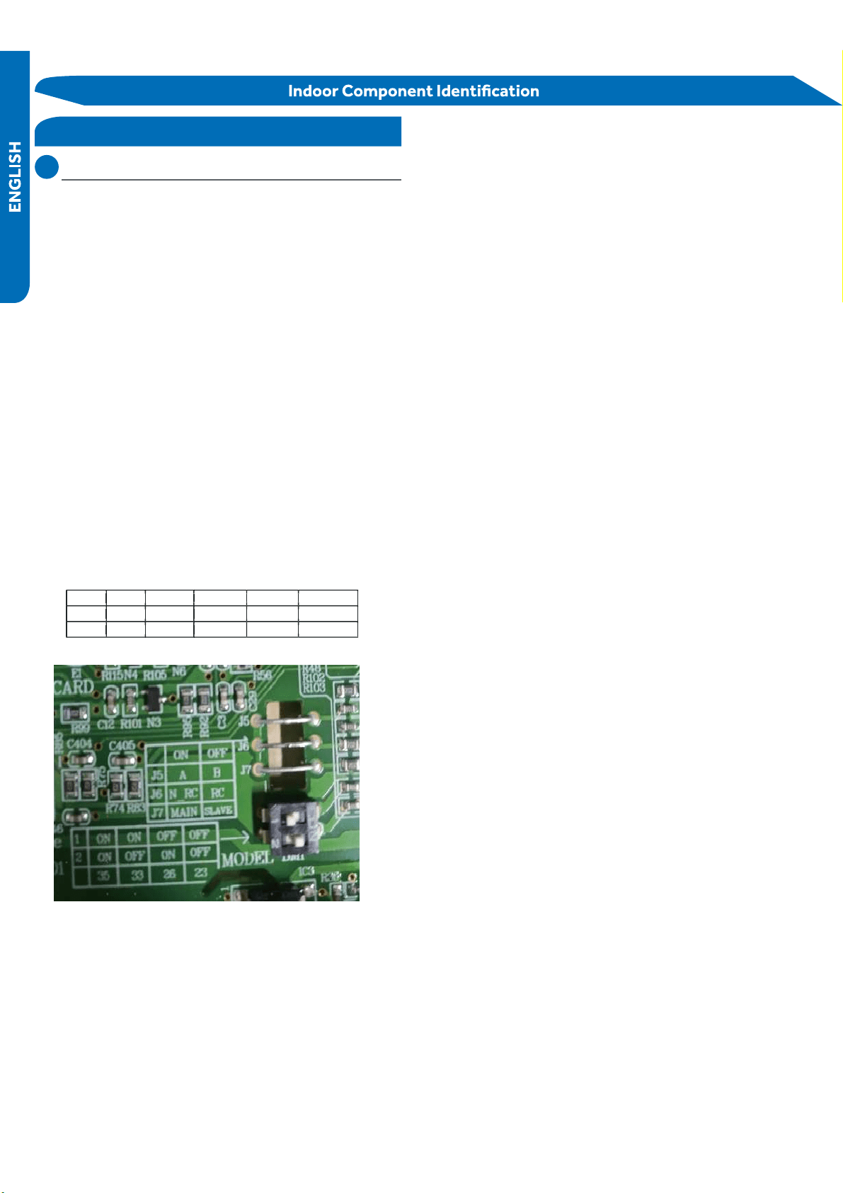
DIP
Switch
Settings
The
PCB
has a set of DIP switches that must be set when
replacing the PCB.
The replacement PCB is shipped with all switches set to the
OFF position.
S
witch
settings:
J5
Selects
remote
code
A
or
B.
Normally
set
to
connection
state
for
code
A
operation.
If
two
indoor
units
are
used
in
the
same
area
and
the
user
wishes
to
control
them
separately,
switch
J5 of
the
sec
ond
unit
is
set
to
be
cut off
for
code
B
operation.
T
he
wireless
remote
for
the
second
unit
is
also
set
to
code
B.
J6
Selects
room
card
able
or
disable.
Normally
set
to
Set
to
when
used
in
conjunction
with
a
room
card
interface
utilized
in ho
tel rooms.
SW-1
and SW-2 Selects EEPROM codes 23, 26, 33 and 35.
Set to
identify
the
tonnage
of
the
unit.
Settings:
9K (23) SW
9K (23) SW
9K (23) SW
-1 OFF SW-2 OFF
-3 OFF SW-4 OFF
-3 OFF SW-4 OFF
-3 OFF SW-4 OFF
12K (26) SW-1 OFF SW-2 ON
12K (26) SW-3 OFF SW-4 ON
12K (26) SW-3 OFF SW-4 ON
12K (26) SW-3 OFF SW-4 ON
12K (26) SW-3 OFF SW-4 ON
12K (26) SW-3 OFF SW-4 ON
18K (33) SW-1 ON
18K (33) SW-3 ON
18K (33) SW-3 ON
18K (33) SW-3 ON
SW
-2 OFF
-4 OFF
DIP Switch
connection
state.
the
disconnected state
PAGE 25
PAGE 26
WALL MOUNT TECHNICAL OVERVIEW
T
he err
or c
odes that ar
e displa
y
ed on the indoor units ma
y vary fr
om the outdoor unit c
odes. T
he inf
ormation c
ommunicated by
Indoor
Display
Outdoor
LED
Diagnosis
F12 1 Outdoor EEPROM failure
F1 2 IPM overcurrent or short circuit
F22 / Outdoor alternating current, over current pr
otection
F3 4 Communication failure between the IPM and outdoor PCB
F20* 5 Module operated overload (compressor overload protection)
F19* 6 Module low or high voltage
F27 / Compressor current sampling circuit fault
F4 8 Overheat protection for discharge temperature
F8* 9 Malfunction of the DC fan motor
F21 10 Malfunction of defrost temperature sensor
F7 11 Suction temperature sensor failure
F6 12 Ambient temperature sensor failure
F25 13 Discharge temperature sensor failure
F30* / High outdoor suction temperature
E7 15 Communication failure between the indoor & outdoor unit
F13* 16 Lack of refrigerant or discharging
F14* 17 4-way valve switching failure
F11 18 Loss of synchronism detection
F28 / Position detection circuit fault of compressor
F15* / Terminal block temp too high
E9 20 Indoor thermal overload
E9* 21 Indoor unit overload protection, heating mode only.
E5 21 Indoor coil frosted
E5* / Indoor anti-frosting protection
F5* 23 Module thermal overload
F2* 24 Compressor start failure, over-current
F23* 25 Phase current protection (IPM)
F9 26 MCU reset
F24 27 Module current detect circuit malfunction
F10 28 Liquid pipe sensor failure: Circuit A
F16 29 Liquid pipe sensor failure: Circuit B
F17 30 Liquid pipe sensor failure: Circuit C
F18 31 Liquid pipe sensor failure: Circuit D
F29 32 Gas pipe sensor failure: Circuit A
F30 33 Gas pipe sensor failure: Circuit B
F31 34 Gas pipe sensor failure: Circuit C
F32 35 Gas pipe sensor failure: Circuit D
F26 36 Gas pipe sensor failure: Circuit E
F34 / Outdoor pipe temperature protection in cooling mode
F35 38 Malfunction of module temperature sensor momentary power failure detection
F36 39 Malfunction of condensing temperature sensor
F33 40 Liquid pipe sensor failure: Circuit E
F38 41 Toci temperature sensor failure
F39 42 High Pressure switch open
F40 43 Low Pressure switch open
F41 44 System high pressure protection: Overcharged, high condensing temperature or malfunction of fan motor.
F42 45 System low pressure protection: Undercharged, low defrosting temperature, or malfunction of fan motor.
F43 / Incorrect match between indoor & outdoor
E1 / Indoor ambient temperature sensor failure
E2 / Indoor coil temperature sensor failure
E4 / Indoor PCB EEPROM failure
E14* / Indoor fan motor malfunction
Emergency button for 15 seconds.
Error Codes
PAGE 27
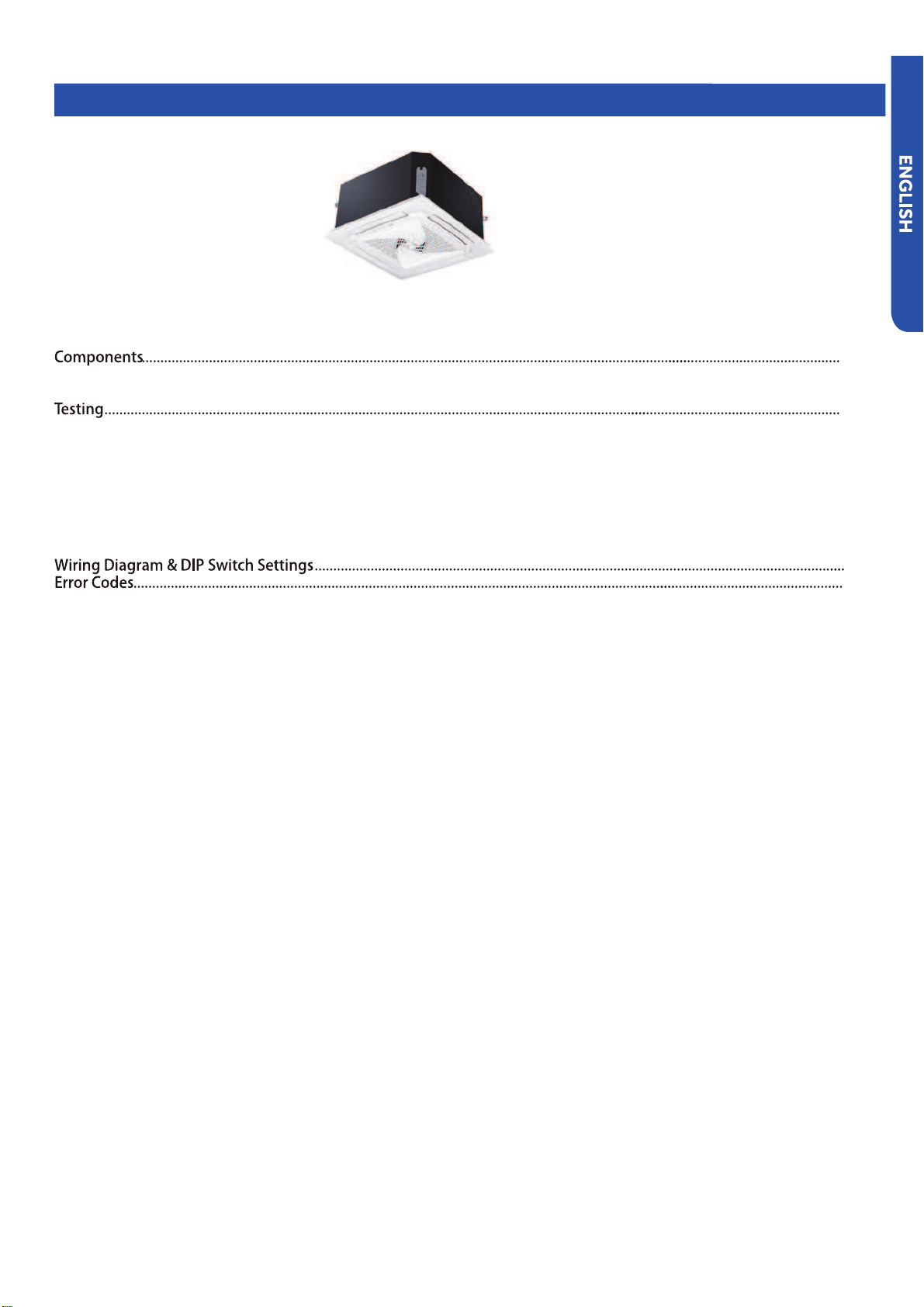
COMPACT CASSETTE TECHNICAL OVERVIEW
COMPACT CASSETTE TECHNICAL OVERVIEW
Table of Contents
Component Overview .........................................................................................................................................................
Cassette Unit Indoor Circuit Board .....................................................................................................................................
Accessing the Blower Motor and Condensate Pump ........................................................................................................
Removing Fan Motor ...........................................................................................................................................................
Removing Condensate Pump .............................................................................................................................................
Ind
oor Fan Motor Test Procedure .......................................................................................................................................
Testing Temperature Sensors ............................................................................................................................................
Testing Louver Motors ........................................................................................................................................................
Testing Communication Circuit ..........................................................................................................................................
Test Condensate Pump and Associated Float Switch ...............................
........................................................................
AB09SC2VHA
AB12SC2VHA
AB18SC2VHA
PAGE 28
29
29
31
32
32
32
32
33
33
34
34
35
36
37
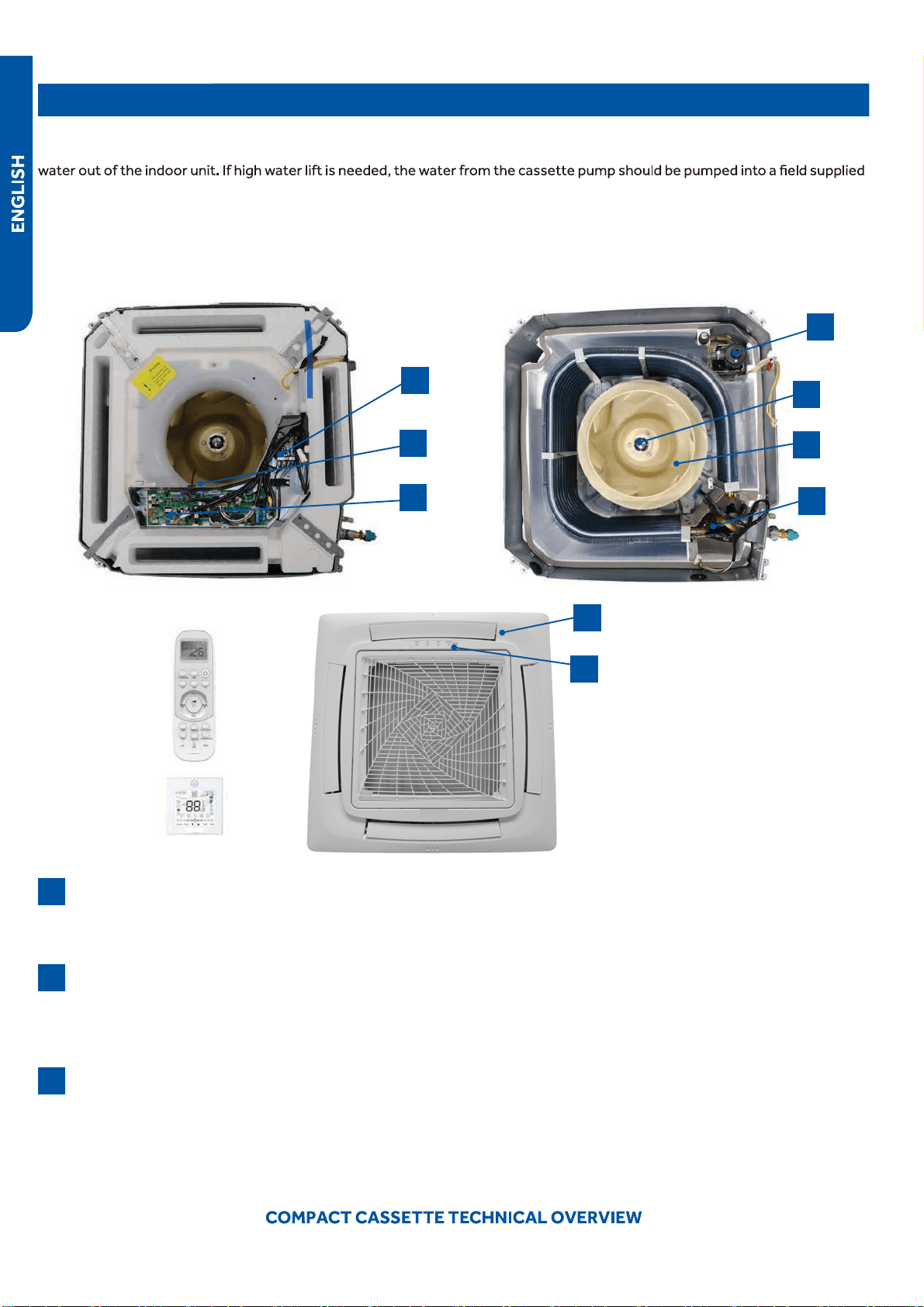
Components
The indoor cassette type units act as evaporator coils during cooling mode and condenser coils during heating mode. These
units have a built in condensate pump with an associated condensate level switch. The condensate pump is capable of lifting
condensate pump with high lift power.
Cassette type indoor units can be operated with a wired controller or a remote control.
Terminal Block
Power to operate the indoor unit comes from the electrical line voltage terminal block at the outdoor unit. The wiring
●
includes 4 wires, 1, 2, 3 and ground. Wires 1 and 3 complete the data path. These wires should always be 14 gauge AWG
Stranded type wire. Splices in wires 1 or 3 may cause communication errors.
Motor Blower
The indoor unit features a multi speed blower motor that will change speed to match the capacity demand from the
●
outdoor unit. Separate motors located in the indoor unit control the operation of the motorized louvers. All of the louver
motors are controlled via commands received from the remote control. The blower motor is controlled by both the remote
●
control and by commands from the outdoor unit ECU.
Display
The indoor unit has a display that communicates system mode. The indoor unit does not display temperatures or
●
diagnostic codes. When a wired controller is used, this information is displayed on the wired controller. It is recommended
to use a wired controller with the cassette unit.
When servicing a diagnostic error, ALWAYS refer to the outdoor unit code to make diagnostic decisions.
Component Overview
1
7
8
3
5
9
2
4
6
1
2
3
PAGE 29
Components
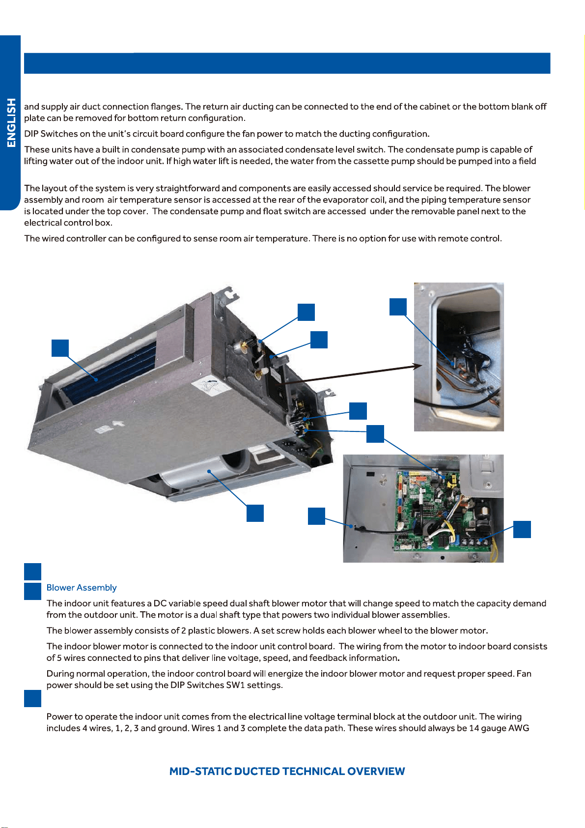
The Blower Assembly
The blower assembly consists of a plastic blower wheel that is connected to a PSC indoor blower motor. A set screw holds
the blower wheel to the blower motor.
The indoor blower motor is a Multi Speed Fan Motor that is connected to the indoor unit control board. The wiring from the
motor to indoor board consists of 4 wires connected to pins common, low , medium and high speeds.
During normal operation, the indoor control board
will energize the indoor blower motor and request proper speed. The
motor has a run capacitor that is located in the Cassette unit’s control box. The run capacitor connects to the motor via
Louver Motors
The louver motors are stepper type motors that move the louvers up/down. The motors are controlled by pulsed voltage
that cannot be measured. If the louver does not move when it should, check for a bind in the louvers.
Piping Temperature Sensor
The Piping Temperature Sensor senses indoor coil temperature in the cooling mode and in the heating mode. This sensor is
used for Anti Freezing and Anti Cold Blow cycles. The sensor also pr
ovides critical temperature information to the ECU that
may be used in frequency adjustments.
Ambient Temperature Sensor
●
The Ambient Temperature Sensor senses room temperature. This sensor provides room temperature information to the
ECU for calculation of inverter capacity and temperature control.
Control Board
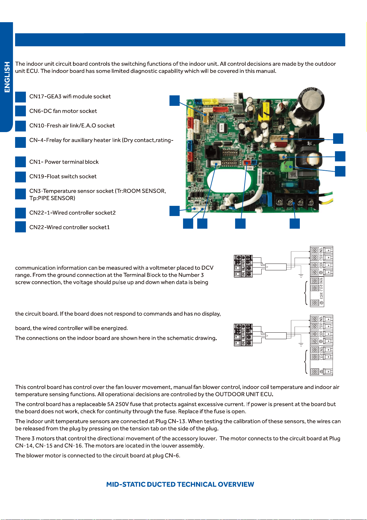
The indoor unit circuit board controls the switching functions of the indoor unit. All control decisions are made by the
outdoor unit ECU. The indoor board has some limited diagnostic capability which will be covered in this manual.
Condensate Pump & Float Switch
4
5
6
7
8
9
PAGE 30
1. If in COOL or DRY mode: Compressor running (Thermal ON), then condensate pump is energized
•When compressor stops (Thermal OFF), condensate pump runs for an additional 5 minutes
2. If in COOL or DRY modes and compressor is running (Thermal ON) and the float switch opens for 5 minutes
•Compressor will stop, the pump will continue to run
•If the float switch does not close, error code will display and pump continues to run
•If the float switch does close, the pump will continue to run for 5 additional minutes
3. During standby (Thermal OFF) in COOL/DRY modes or in HEAT and FAN modes and float switch opens for 2 seconds,
the condensate pump is energized.
•If the float switch closes, the pump will run an additional 5 minutes
•If the float does not close, the pump continues to run and error code is displayed
Components
The indoor unit circuit board controls the switching functions
of the indoor unit. All control decisions are made by the
outdoor unit ECU. The indoor board has some limited
diagnostic capability which will be covered in this manual.
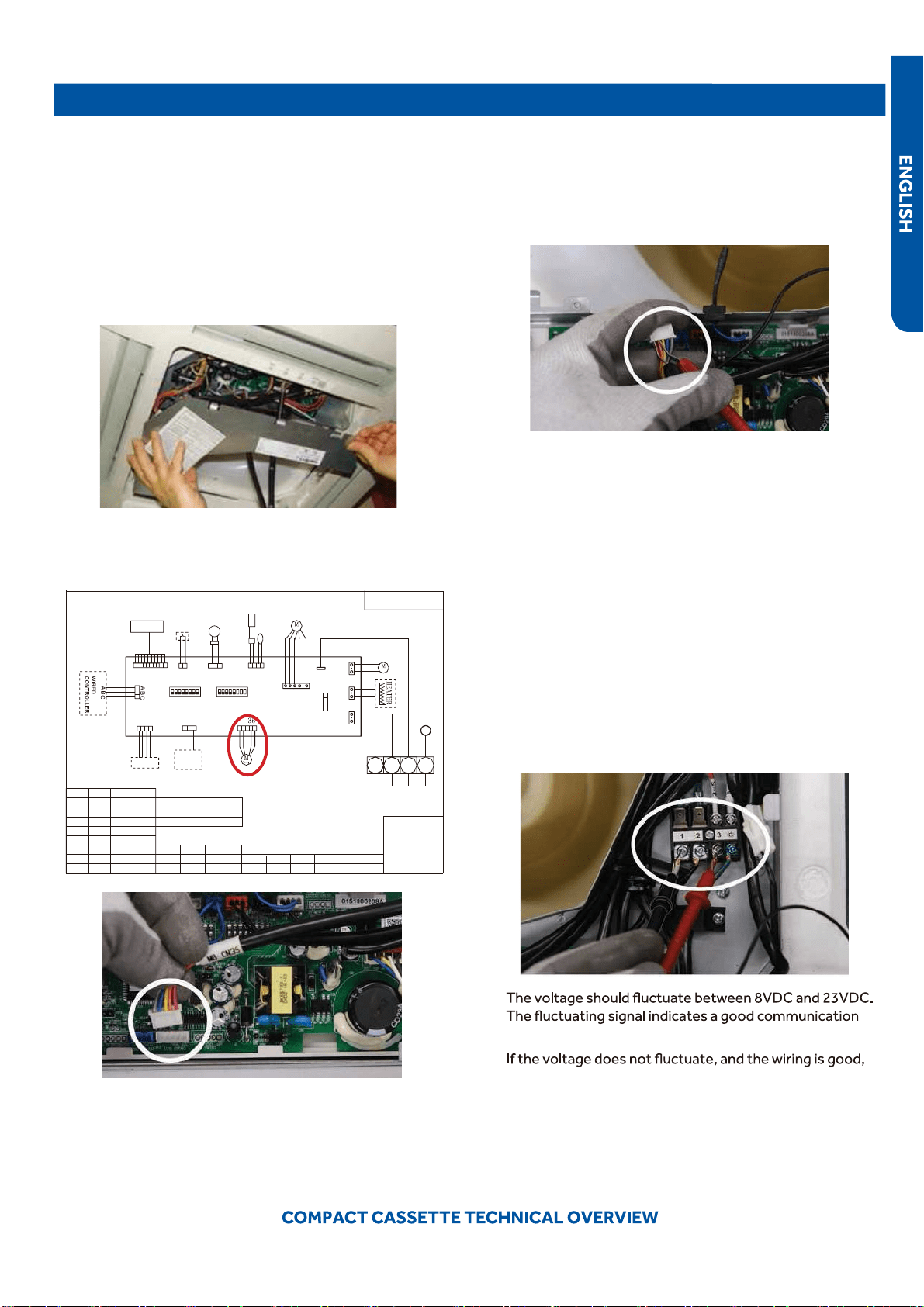
The Indoor Unit Circuit Board communicates with the outdoor
unit ECU via a connection at Terminal Block screw 3. The
data pulse that sends the communication information can be
measured with a voltmeter placed to DCV range. From the
ground connection at the Terminal Block to the Number 3
screw connection, the voltage should pulse up and down when
data is being transmitted.
This control board has control over the fan louver movement,
manual fan blower control, indoor coil temperature and indoor
air temperature sensing functions. All operational decisions
are controlled by the OUTDOOR UNIT ECU.
The connections on the indoor board are shown here in the
schematic drawing.
Line voltage to power the indoor unit comes in on Terminal
Block connections 1 and 2. Power connects from these
terminal connections to CH- 3 and CH-4 on the circuit board.
If the board does not respond to commands and has no
display, check for line voltage at these connections. When
power is present at the indoor board, the Display Power
Indicator will be lit.
The control board has a replaceable 3.15A 250V fuse that
protects against excessive current. If power is present at
the board but the board does not work, check for continuity
through the fuse. Replace if the fuse is open.
The indoor unit temperature sensors are connected at
Plug CN-13. When testing the calibration of these sensors,
the wires can be released from the plug by pressing on the
tension tab on the side of the plug.
The receiver/display unit that is mounted to the front
cover of the indoor unit plugs into the circuit board via a
connection at Plug CN-29.
There is one motor that controls the movement of the
louvers. The motor connects to the circuit board at Plug CN-
14. The motor is located in the over of the louver assembly.
The blower/fan motor is connected to the circuit board at
plug CN-11.
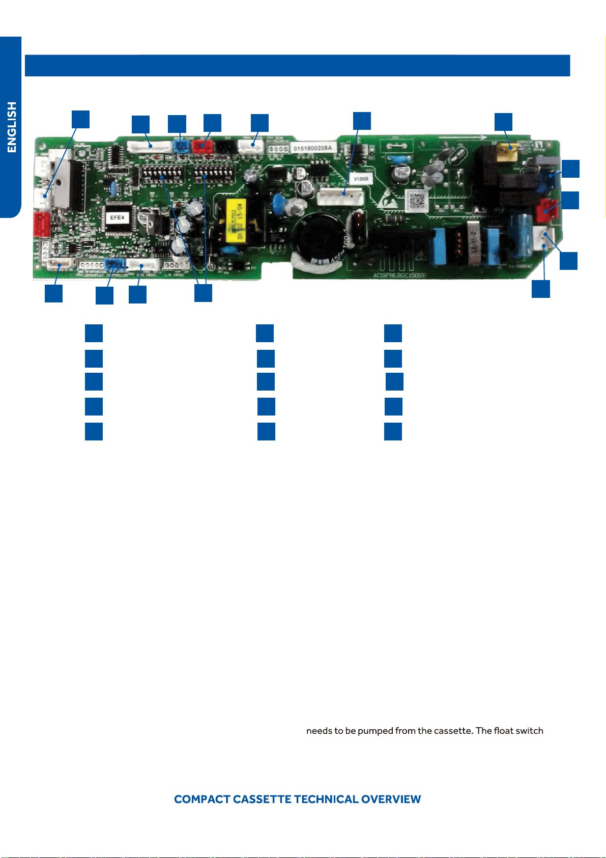
The Cassette unit has a built in condensate pump. The pump
is connected to the circuit board on Plug CN-9. The pump
is energized whenever the Float Switch indicates that water
connects onto the circuit board via Plug CN-18.
1
4
7
10
13
2
5
8
11
14
3
N Terminal
L Terminal
Communication Terminal
3.15A 250V Fuse
CN3 Pipe/Room Temp Sensors
1
4
2
5
3
6
9
12
15
7
10
8
6
9
CN19 Float Switch
CN21 Louver Panel
CN11 Wired Remote
DIP Switches
CN35 Stepper Motor
13
11
14
12
15
CN6 Fan Motor
CN9 Condensate Pump
CN4 U-HOME
CN13 Remote Central
CN1 Room Card
Cassette Unit Indoor Circuit Board
PAGE 31
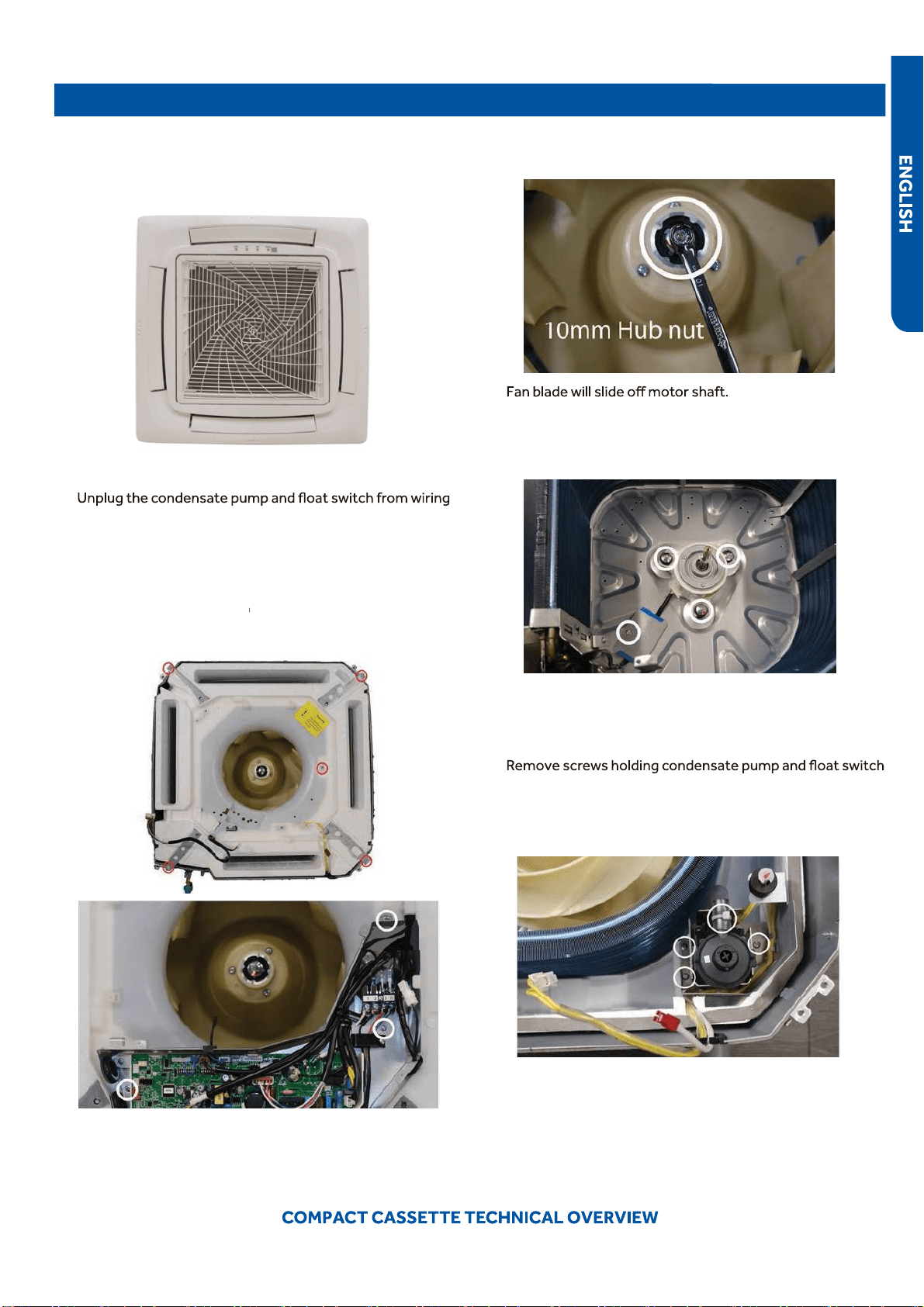
Testing
Accessing the Blower Motor and Condensate Pump
1.
Disconnect power to the outdoor unit.
2.
Remove the louver assembly.
Removing Fan Motor
1.
Remove holding nut from fan blade.
Removing Condensate Pump
●
1.
in position.
2.
Disconnect condensate hose from condensate pump.
3.
Remove assembly.
8.
Slide condensate pan from cassette.
2.
3.
Remove Phillips head screw holding cover plate over mo
tor
wiring leads.
4.
Remove 3 nuts that hold fan motor in place.
5.
Fan motor will come loose.
3.
Disconnect the main power wire t
o the indoor unit.
4.
harness.
5.
Unplug fan motor from wiring harness.
6.
Remove ground wire from gr
ound screw on electrical
box. Remove electrical box.
7.
Remove 5 screws holding f
oam condensate pan bottom in
ding f
ding f
place.
PAGE 32
Testing
Indoor Fan Motor Test Procedure
If the indoor fan motor does not run:
●
1. Disconnect power to the system.
2. Remove the return air cover and access the circuit board connection.
3. Reset power and turn the remote control fan command to Fan On mode.
Testing Temperature Sensors
●
The easiest problems to solve will involve codes that are related to potential failure of temperature sensors. Common problems
●
may include loose connections, open electrically, and out of calibration. Checking the condition of the sensors requires a
temperature probe and an ohmmeter.
The Reference Section of this manual contains temperature resistance tables that can be used to check the calibration of the
sensors. The measured resistance must be within the tolerances printed on the top of the tables.
To test the electrical condition of a temperature sensor perform the following:
1.
2. Remove the sensor wires form the connection plug by releasing holding tension on the plugs tension tab.
3. Use an ohmmeter to test the electrical resistance of the sensor.
4. Measure the air temperature near the sensor and compare the required resistance against measured resistance. (See chart in
reference section) If the sensor is within calibration, the sensor is good. If the sensor is out of calibration, replace the sensor.
●
(Tube Sensors should be removed from socket and exposed to air temperature during test.)
Motor Test:
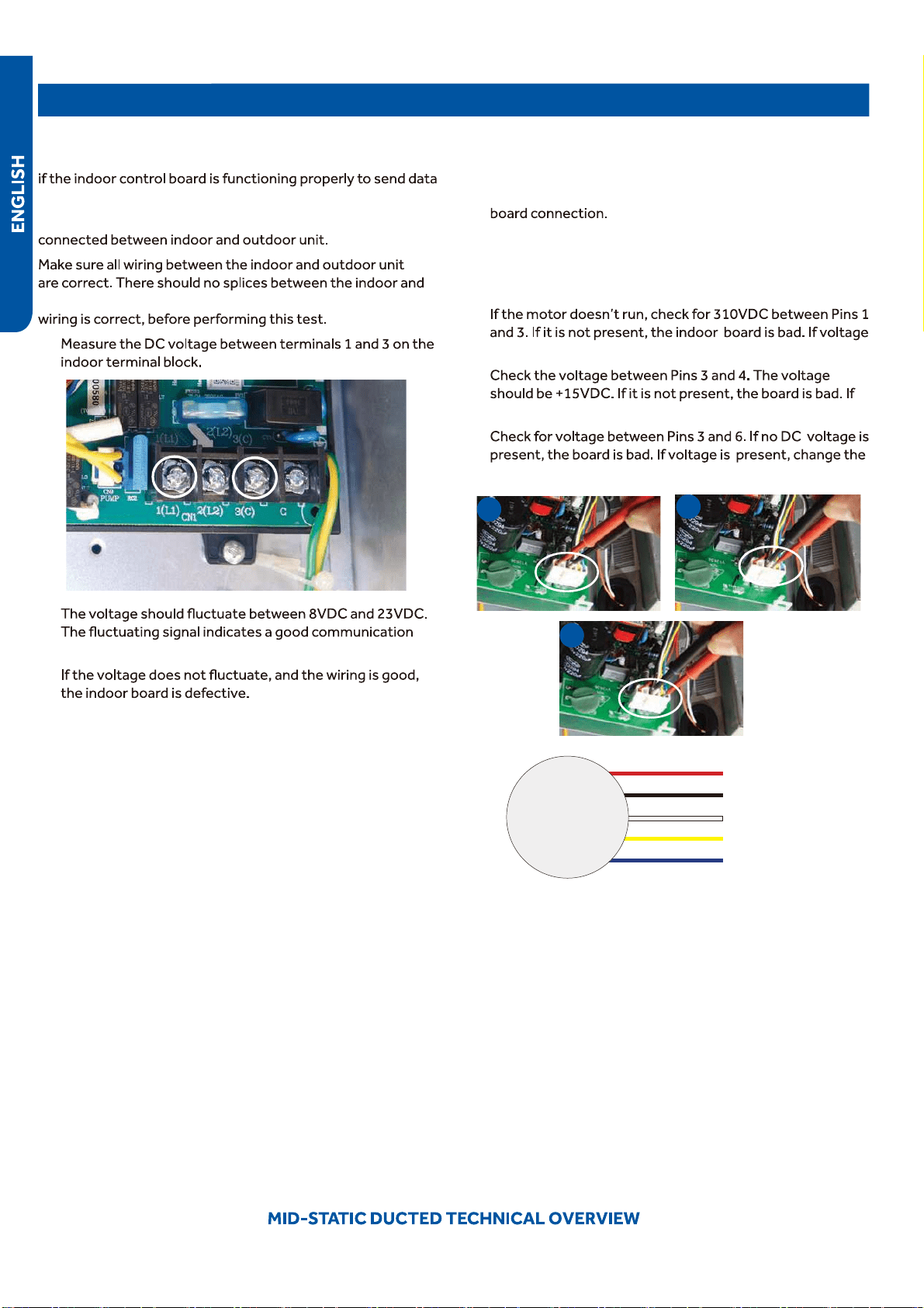
1. If the motor doesn’t run, check for 310VDC between Pins 1
and 3. If it is not present, the indoor board is bad. If voltage
is present, continue on.
2. Check the voltage between Pins 3 and 4. The voltage
should be +15VDC. If it is not present, the board is bad. If
voltage is present, continue on.
3. Check for voltage between Pins 3 and 6. If no DC voltage
is present, the board is bad. If voltage is present, change
the motor.
2 4
PAGE 33
TO OUT DOOR
0150515406
BM1-1
BM1-7
BM1-8
TYPE DEFINE
OFFOFF
BM1-2 BM1-3
BTU
B:BLACK
R:RED
W:WHITE
Y/G:YELLOW/GREEN
TEMP.
●
SENSOR
ROOM
SENSOR
FLOAT
SWITCH
PUMP
UP/DOWN
CN9
CN1
CN6
PANNEL
CN4
CN11
CN19
CN13
CN3
ON
CN
CN21
T5A/250VAC
FUSE
BM3
2
●
1
3
B
W
R
Y/G
OFF OFF OFF
ON OFF OFF
OFF ON OFF
ON ON OFF
OFF OFF ON
ON OFF ON
OFF ON ON
ON ON ON
9000
12000
18000
24000
28000
36000
48000
60000
NOTE1.DASHED PART ARE OPTIONAL.
2. USER SHOULD NOT TO SET BM1 AND BM3
CH1
OFF OFF
BM1-4 BM1-5
BM1-6
OFF
OFF
CN16
G
CN8
G
TEMP.
PIPING
DC FAN
ROOMCARD
U-HOME
REMOTE
CENTRAL
87654321
ON
BM1
OFF
87654321
N
OFF
Room card
available
unavailable
ON
AB09SC2VHA/AB09CS2ERA
●
AB12SC2VHA/AB12CS2ERA(S)
AB18SC2VHA/AB18CS2ERA(S)
Default
Testing
Testing Louver Motors
If the louver does not operate with command from the remote
control, either the indoor board is bad, or the louver motor
is defective. It is more likely the motor is defective than the
board. (Make sure the louver assembly is not binding and
keeping the vanes from moving.)
1. Remove power from the unit and remove the indoor unit
cover.
2. Access the circuit board.
3. Identify the inoperable louver motor on the schematic
drawing below and disconnect the plug from the circuit
board.
4. Use an Ohmmeter to test the electrical continuity of the
louver motor windings. The proper resistance for each
winding can be found in this table. If the motor winding
resistance is erratic or shows open, the motor is defective.
Replace the motor.
5. If the motor checks out good, replace the indoor control
board.
Testing Communication Circuit
If an Error E7 occurs, perform the following test to determine
if the indoor control board is functioning properly to send data
to the outdoor unit.
Perform this test with the unit powered and all wiring
connected between indoor and outdoor unit.
Make sure all wiring between the indoor and outdoor unit
are correct. There should no splices between the indoor and
outdoor unit wiring connecting terminals 1 or 3. Make sure
wiring is correct, before performing this test.
1. Measure the DC voltage between terminals 1 and 3 on the
indoor terminal block.
2.
path.
3.
the indoor board is defective.
●
PAGE 34
Testing
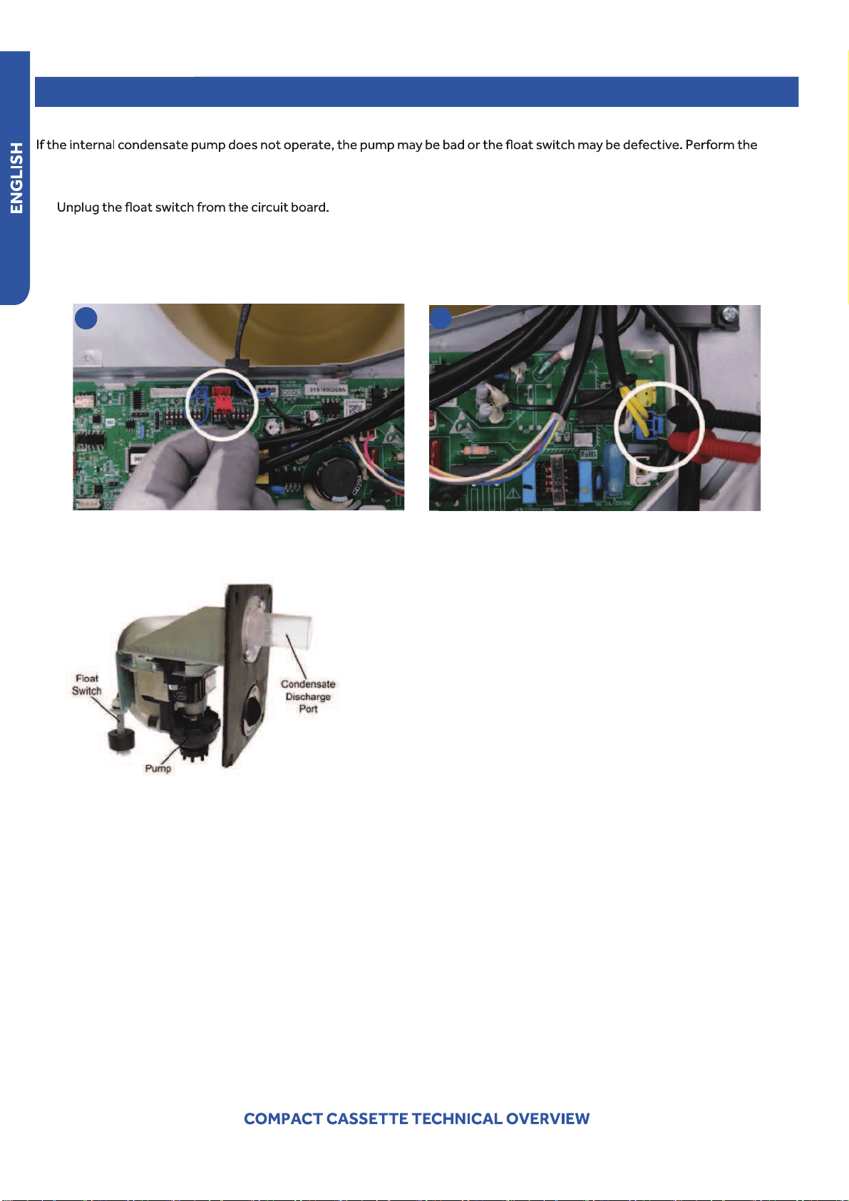
Test Condensate Pump and Associated Float Switch
following test:
1. Access the electrical control box.
●
2.
3. The pump should start.
4. If the pump does not start, check for voltage at the pump connector on the board. There should be 230 Volts AC to the pump.
If there is not, the circuit board is defective. If there is proper voltage to the pump, either the pump or associated pump wiring
is defective.
2 4
PAGE 35
5.
When installing, the condensate discharge port at the top of the water pump must be connected with drian pipe.
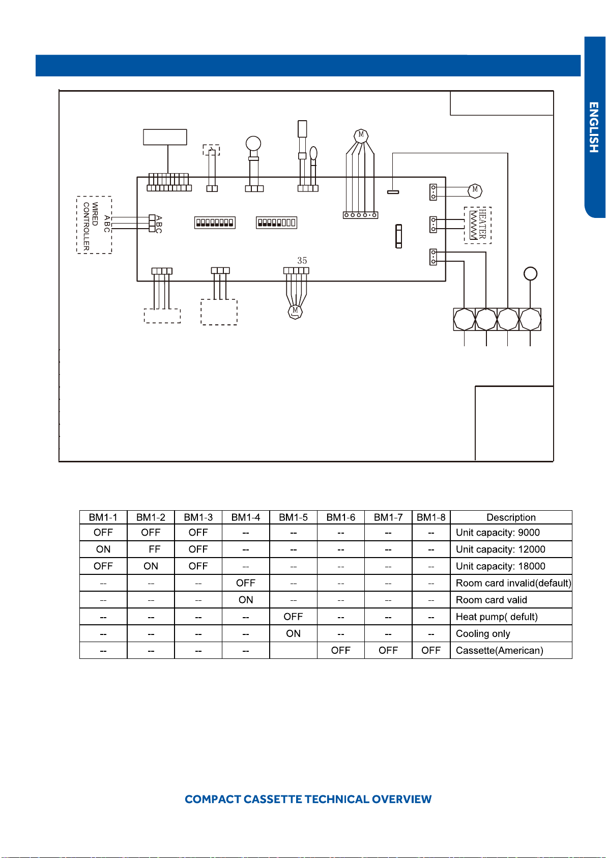
Wiring Diagram & DIP Switch Settings
O
Cassette Unit DIP Switch Settings
TO OUT DOOR
0150515406
BM1-1
BM1-7
BM1-8
TYPE DEFINE
OFFOFF
BM1-2 BM1-3
BTU
B:BLACK
R:RED
W:WHITE
Y/G:YELLOW/GREEN
TEMP.
SENSOR
ROOM
SENSOR
FLOAT
SWITCH
PUMP
UP/DOWN
CN9
CN1
CN6
PANNEL
CN4
CN11
CN19
CN13
CN3
ON
CN
CN21
T5A/250VAC
FUSE
BM3
2
1
3
B
W
R
Y/G
OFF OFF OFF
ON OFF OFF
OFF ON OFF
ON ON OFF
OFF OFF ON
ON OFF ON
OFF ON ON
ON ON ON
9000
12000
18000
24000
28000
36000
48000
60000
NOTE1.DASHED PART ARE OPTIONAL.
2. USER SHOULD NOT TO SET BM1 AND BM3
CH1
OFF OFF
BM1-4
BM1-5
BM1-6
OFF
OFF
CN16
G
CN8
G
TEMP.
PIPING
DC FAN
ROOMCARD
U-HOME
REMOTE
CENTRAL
87654321
ON
BM1
OFF
87654321
N
OFF
Room card
available
unavailable
ON
AB09SC2VHA/AB09CS2ERA
AB12SC2VHA/AB12CS2ERA(S)
AB18SC2VHA/AB18CS2ERA(S)
Default
PAGE 36
Error Codes
The error codes that are displayed on the indoor units may vary from the outdoor unit codes. The information communicated by
Indoor
LED5
Indoor
LED1
Outdoor
LED
Diagnosis
2 1 1 Outdoor EEPROM failure
2 2 2 IPM overcurrent or short circuit
2 3 / Outdoor alternating current, over current protection
2 4 4 Communication failure between the IPM and outdoor PCB
2 5 5 Module operated overload (compressor overload protection)
2 6 6 Module low or high voltage
2 7 / Compressor current sampling circuit fault
2 8 8 Overheat protection for discharge temperature
2 9 9 Malfunction of the DC fan motor
3 0 10 Malfunction of defrost temperature sensor
3 1 11 Suction temperature sensor failure
3 2 12 Ambient temperature sensor failure
3 3 13 Discharge temperature sensor failure
3 4 / High outdoor suction temperature
3 5 15 Communication failure between the indoor & outdoor unit
3 6 16 Lack of refrigerant or discharging
3 7 17 4-way valve switching failure
3 8 18 Loss of synchronism detection
3 9 / Position detection circuit fault of compressor
4 0 / Terminal block temp too high
●
4 0 20 Indoor thermal overload
4 1 21 Indoor unit overload protection, heating mode only.
4 1 21 Indoor coil frosted
4 2 / Indoor anti-frosting protection
4 3 23 Module thermal overload
4 4 24 Compressor start failure, over-current
4 5 25 Phase current protection (IPM)
4 6 26 MCU reset
4 7 27 Module current detect circuit malfunction
4 8 28 Liquid pipe sensor failure: Circuit A
4 9 29 Liquid pipe sensor failure: Circuit B
5 0 30 Liquid pipe sensor failure: Circuit C
5 1 31 Liquid pipe sensor failure: Circuit D
5 2 32 Gas pipe sensor failure: Circuit A
5 3 33 Gas pipe sensor failure: Circuit B
5 4 34 Gas pipe sensor failure: Circuit C
5 5 35 Gas pipe sensor failure: Circuit D
5 6 36 Gas pipe sensor failure: Circuit E
5 7 / Outdoor pipe temperature protection in cooling mode
5 8 38 Malfunction of module temperature sensor momentary power failure detection
5 9 39 Malfunction of condensing temperature sensor
6 0 40 Liquid pipe sensor failure: Circuit E
●
6 1 41 Toci temperature sensor failure
6 2 42 High Pressure switch open
6 3 43 Low Pressure switch open
6 4 44 System high pressure protection: Overcharged, high condensing temperature or malfunction of fan motor
6 5 45 System low pressure protection: Undercharged, low defrosting temperature, or malfunction of fan motor
6 6 / Incorrect match between indoor & outdoor
0 1 / Indoor ambient temperature sensor failure
0 2 / Indoor coil temperature sensor failure
0 4 / Indoor PCB EEPROM failure
0 7 / Communication fault between the indoor and outdoor unit
0 8 / Communication fault between the controller and Indoor unit
0 12 / Drain system malfunction
0 13 / Zero cross signal detected wrong
0 14 / Indoor fan motor malfunction
PAGE 37
39
39
41
42
44
44
45
45
46
47
47
47
48
49
50
55
43
44
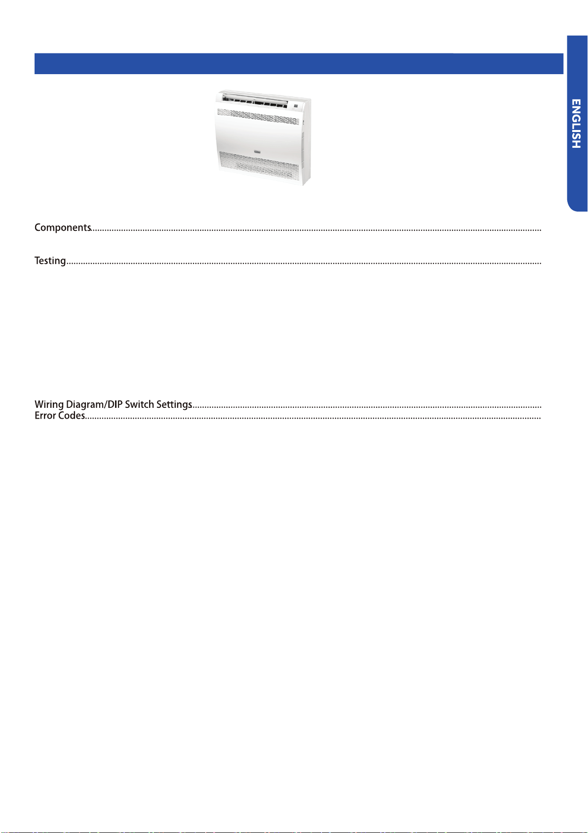
ComponentsComponents
The Mid-Static Ducted Indoor Unit will act as evaporator coils during cooling mode and condenser coils during heating mode.
This unit can operate with a motorized supply air louver or it can have a LIMITED amount of ducting added to the unit’s return
supplied condensate pump with high lift power.
All operating status and information is displayed on the wired controller. The Mid-Static Ducted unit does not have a display.
8
●
9
6
4
●
2
2
7
5
3
3
1
1
Evaporator Coil
Terminal Block
●
Stranded type wire. Splices in wires 1 or 3 may cause communication errors.
●
Component Overview
●
PAGE 39
ComponentsComponents
PAGE 40
4
5
6
7
8
9
1. If in COOL or DRY mode: Compressor running (Thermal ON), then condensate pump is energized
•When compressor stops (Thermal OFF), condensate pump runs for an additional 5 minutes
2. If in COOL or DRY modes and compressor is running (Thermal ON) and the float switch opens for 5 minutes
•Compressor will stop, the pump will continue to run
•If the float switch does not close, error code will display and pump continues to run
•If the float switch does close, the pump will continue to run for 5 additional minutes
3. During standby (Thermal OFF) in COOL/DRY modes or in HEAT and FAN modes and float switch opens for 2 seconds,
the condensate pump is energized.
•If the float switch closes, the pump will run an additional 5 minutes
•If the float does not close, the pump continues to run and error code is displayed
8
6
4
7
5
Control Board
ECU for calculation of inverter capacity and temperature control.
Piping Temperature Sensor
The Piping Temperature Sensor senses indoor coil temperature in the cooling mode and in the heating mode. This sensor is
used for Anti Freezing and Anti Cold Blow cycles. The sensor also provides critical temperature information to the ECU that
Condensate Pump
Gravity Drain Ports
WiFi
The unit comes shipped with a WiFi module that provides control via a smartphone app.
●
9
Components
The Indoor Unit Circuit Board communicates with the outdoor unit ECU
via a connection at Terminal Block screw 3. The data pulse that sends the
transmitted.
Line voltage to power the indoor unit comes in on Terminal Block connections
1 and 2. Power connects from these terminal connections to CH- 1 and CH-2 on
check for line voltage at these connections. When power is present at the indoor
Indoor Unit Circuit Board
9
8
7
6
1
2
3
4
5
230VAC ,3A)
6 578
2
1
9
3
4
PAGE 41
Components
Fresh Air Function
When a call for Fresh Air is received, via the wireless or wired
Call for Fresh Air is Received:
OFF cycle after the compressor starts.
●
•
controller or wireless remote controller)
•
• The compressor stops.
In Fan Only mode:
OFF cycle
•
controller or wireless remote controller)
•
In Heating mode
OFF cycle after the compressor starts.
•
controller or wireless remote controller)
•
• The compressor stops.
• The system enters into Defrost Cycle.
Special Fresh Air Function (Canadian Ventilation Mode - Mid
Static Ducted Only)
when DIP switch SW3_1 is set to OFF position.
the the unit will proceed Continuous Fresh Air, keeping
the Indoor Fan Motor energized even if the compressor is
setpoint=customer set point + compensation point).
Notes:
• During an active Call, the fan motor speed will be whatever
the fan motor speed will be set to a special Low setting that
corresponds to the ESP setting.
• During a Defrost Cycle, the indoor fan is disabled, along with
the Fresh Air Function
PAGE 42
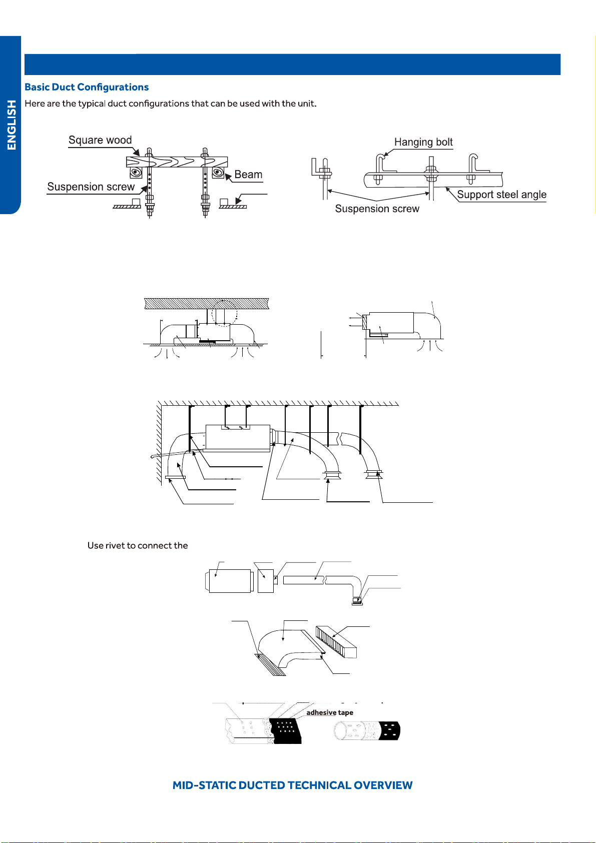
Ductwork / Grilles
Ductwork Installation
air return duct on the air
return inlet of the indoor
unit, then connect the
other end with the air
return
Indoor unit
Soft
connection
or static
box
Transition
duc
t
Rounded
duc
t
Tie-in of air
distribution
Air dis
tribution
Air return blind Air return duct
Indoor unit
Rivet
gluey nail
heat
preservation cotton
tinfoil
gluey nail cap
Roof Installation
Ceiling
Ceiling
Air supply
Air supply
Air supply
Unit
Return air
Return air box
Roof
Air outlet grill
Air outlet grill
Air supply
Air supply
Air supply
Air supply
Unit
Return air box
Return air box
Return air
Long Duct
Suspending hook
Suspending hook
Suspending hook
Drain pipe
Drain pipe
Air return duct
Air return blind
Air out duct
Air out duct
Transition duct
Tie-in of air
Distribution
Air distribution
PAGE 43
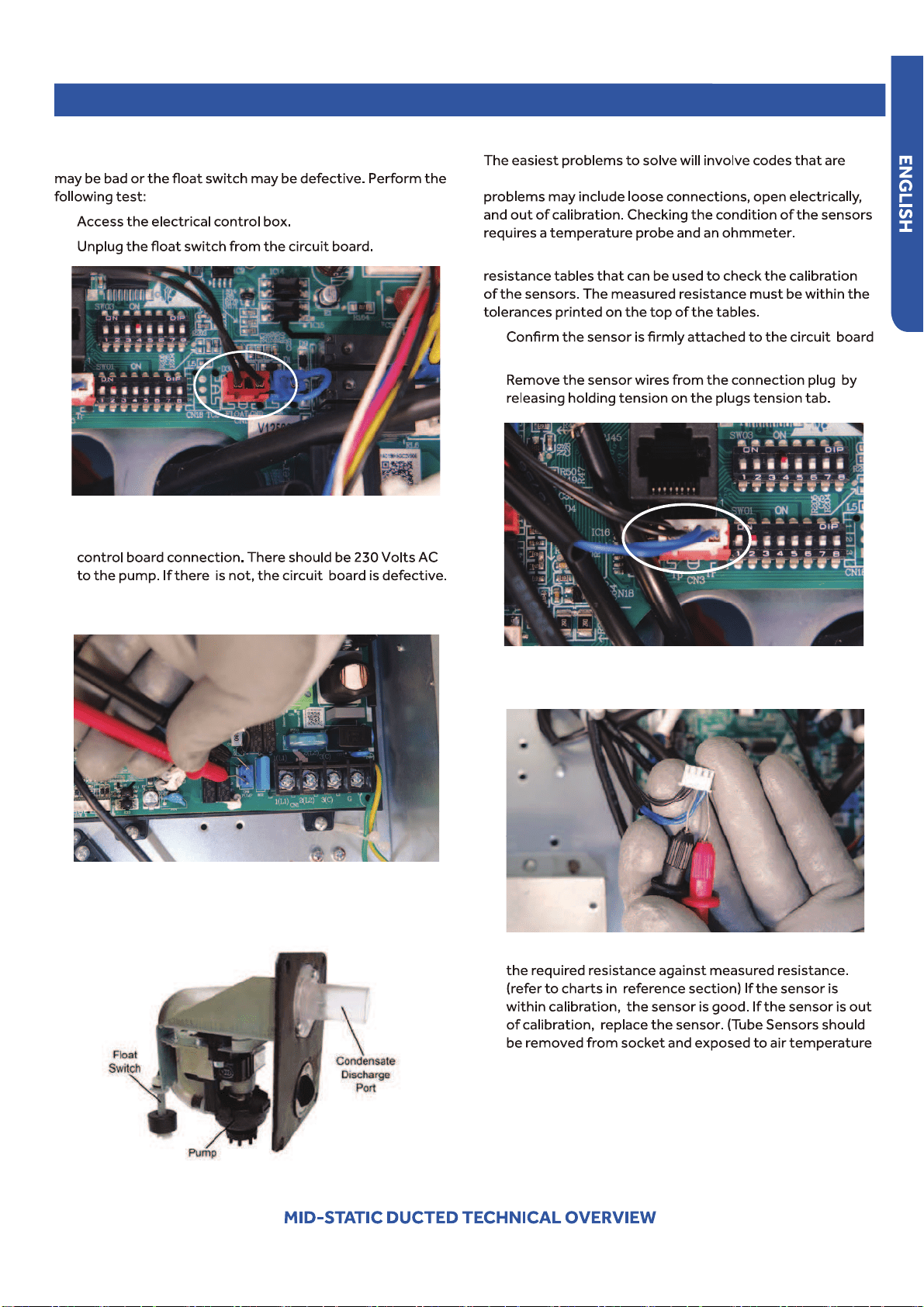
Testing
Testing Temperature Sensors
related to potential failure of temperature sensors. Common
The Reference Section of this manual contains temperature
1.
connection plug.
2.
Test Condensate Pump and Associated Float Switch
If the internal condensate pump does not operate, the pump
1.
2.
3. The pump should start.
4. If the pump does not start, check for voltage at the pump
●
If there is proper voltage to the pump, either the pump or
associated pump wiring is defective.
3.
●
Use an ohmmeter to test the electrical resistance of the
sensor.
4.
●
Measure the air temperature near the sensor and compare
during test.)
●
PAGE 44
5.
When installing, the condensate discharge port at the
top of the water pump must be connected with drian
pipe.
Testing
Testing Communication Circuit
If an Error E7 occurs, perform the following test to determine
to the outdoor unit.
Perform this test with the unit powered and all wiring
●
outdoor unit wiring connecting terminals 1 or 3. Make sure
1.
2.
path.
3.
If The Indoor Fan Motor Does Not Run:
1. Remove the front cover and access the fan motor circuit
2. Reset power and turn the remote control fan command to
Fan On mode.
Motor Test:
1.
is present, continue on.
2.
voltage is present, continue on.
3.
motor.
Indoor Fan Motor Voltage Check
1
2
3
PAGE 45
Testing
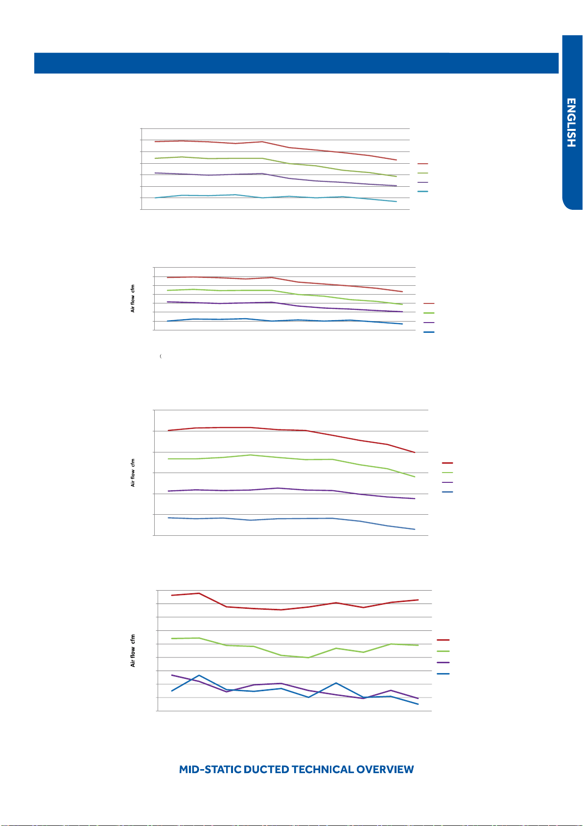
Static Pressure Charts
205
255
305
355
405
455
505
555
0.1 0.15 0.2 0.28 0.36 0.4 0.44 0.48 0.52 0.6
●
Static pressure (in.wc.)
High(cfm)
Med(cfm)
Low(cfm)
Quiet(cfm)
USYM09UCDSA
205.0
●
255.0
305.0
355.0
405.0
455.0
505.0
555.0
External
●
static
pressure
in. wc.)
0.10 0.15 0.20 0.28 0.36 0.40 0.44 0.48 0.52
Static pressure (in.wc.)
High(cfm)
Med(cfm)
Low(cfm)
Quiet(cfm)
USYM12UCDSA
350.0
●
400.0
450.0
500.0
550.0
600.0
650.0
0.10 0.15 0.20 0.28 0.36 0.40 0.44 0.48 0.52 0.60
Static pressure (in.wc.)
High(cfm)
Med(cfm)
Low(cfm)
Quiet(cfm)
USYM18UCDSA
400.0
●
450.0
500.0
550.0
600.0
650.0
700.0
750.0
800.0
850.0
0.10 0.15 0.20 0.28 0.36 0.40 0.44 0.48 0.52 0.60
Static pressure (in.wc.)
High m3/h
Med m3/h
Low m3/h
Quiet m3/h
USYM24UCDSA
PAGE 46
Testing
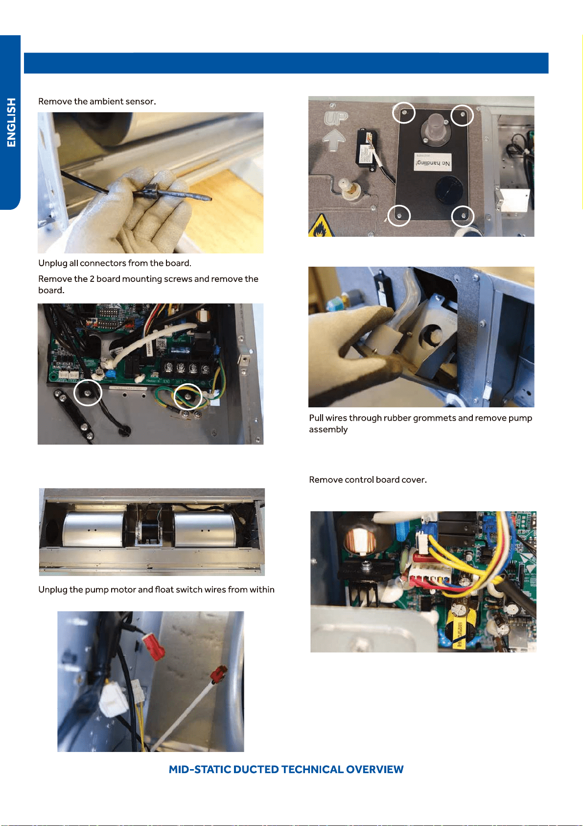
Board Replacement
1.
Removing the Condensate Pump
●
1. Remove the air inlet cover.
2.
3.
2.
the air inlet
3. Remove the 4 screws holding the pump in place.
4. Tilt the pump out from the top and pull out
5.
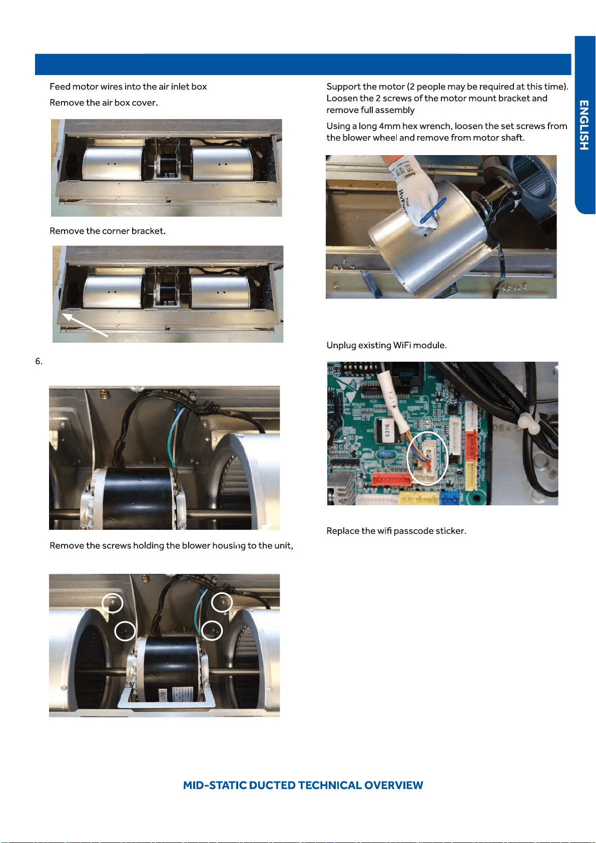
Removing Fan Motor
1.
2. Unplug motor wires.
PAGE 47
Testing
3.
4.
5.
Remove the ground screw and fr
●
ee the motor wire
harness.
7.
4 on each housing.
8.
9.
Replacing WiFi Module
1.
2. Insert new WiFi module.
3.
4. Pair the unit to account.
PAGE 48
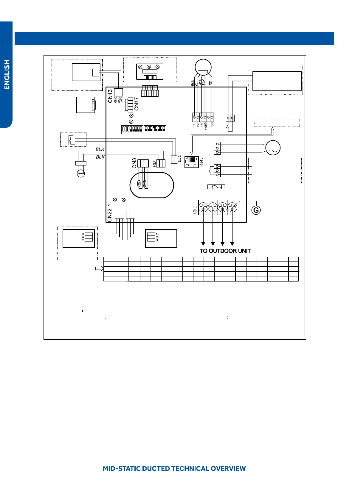
Wiring Diagram
FRELAY FOR FRESH AIR
●
MOTOR(dry Contact
,rating-230VAC,3A) /E.A.0
FUSE
T250V 5A
1(L1)
G
AC PUMP
MOTOR
DC FAN
MOTOR
A B
C
A B
C
Tp
Tr
CN16
ROOM CARD
FLOAT SWITCH
ON ON
YCJ-A002
INFRARED SIGNAL RECEIVER
TO RJ 45 device
CN22
LED2
LED1
SW01
SW03
CN21
CN6
CN20
LED3
LED4
Y/G
YL
YL
CN19
CN9
CN10
REMOTE
CENTRAL
CONTROL
ADAPTOR
2(L2) 3
NOTE:
1.Dashed parts are optional.
2.Please refer to service manual to get details of the DIP switches definition .
3.Do not change the DIP switches setting without technical support.
4.Get details from trouble shooting list about LED indication.
5.Abbreviation
●
RD -red, W -withe, BLK -black,BLU-blue,GRN-green,YL-yellow,Y/G -yellow/green
,
E.A.O:
external alarm output,Tr
indoor unit ambient(room) temperature sensor,Tp indoor unit pipe(coil)
temperature sensor.
6.The port CN4&CN10are dry contact output port for particular use,do not connect other device without
technical person suppo
●
rt.
M
M
WIRED
CONTROLLER
WIRED
CONTROLLER
1 2 3
4 5
6
7
8
1 2 3
4 5
6
7
8
CN4
P1 P2
RELAY FOR AUXILIARY
(dry contact port,contact
rating 230VAC,3A
BLU
GRN
BLU
W
BLK
W
W
Factory default setting
of the DIP switches
SW1-1 SW1-2 SW1-3 SW1-4 SW1-5 SW1-6 SW1-7 SW1-8 SW3-1 SW3-2 SW3-3 SW3-4 SW3-5 SW3-6 SW3-7 SW3-8
USYM
09UCDSA1
USYM
12UCDSA1
USYM
18UCDSA1
USYM
24UCDSA1
MODEL
OFF OFF OFF OFF OFF OFF OFF OFF OFF OFF OFF OFF OFF OFF OFF
ON
12V
COM
GND
W
W
WiFi MODULE
W
ON OFF OFF OFF OFF OFF OFF OFF OFF OFF OFF OFF OFF OFF OFF
ON
OFF OFF OFF OFF OFF OFF OFF OFF OFF OFF OFF OFF OFFOFF ON
ON ON
OFF OFF OFF OFF OFF OFF OFF OFF OFF OFF OFF OFF OFF
ON
ON
0151539442
●
PAGE 49
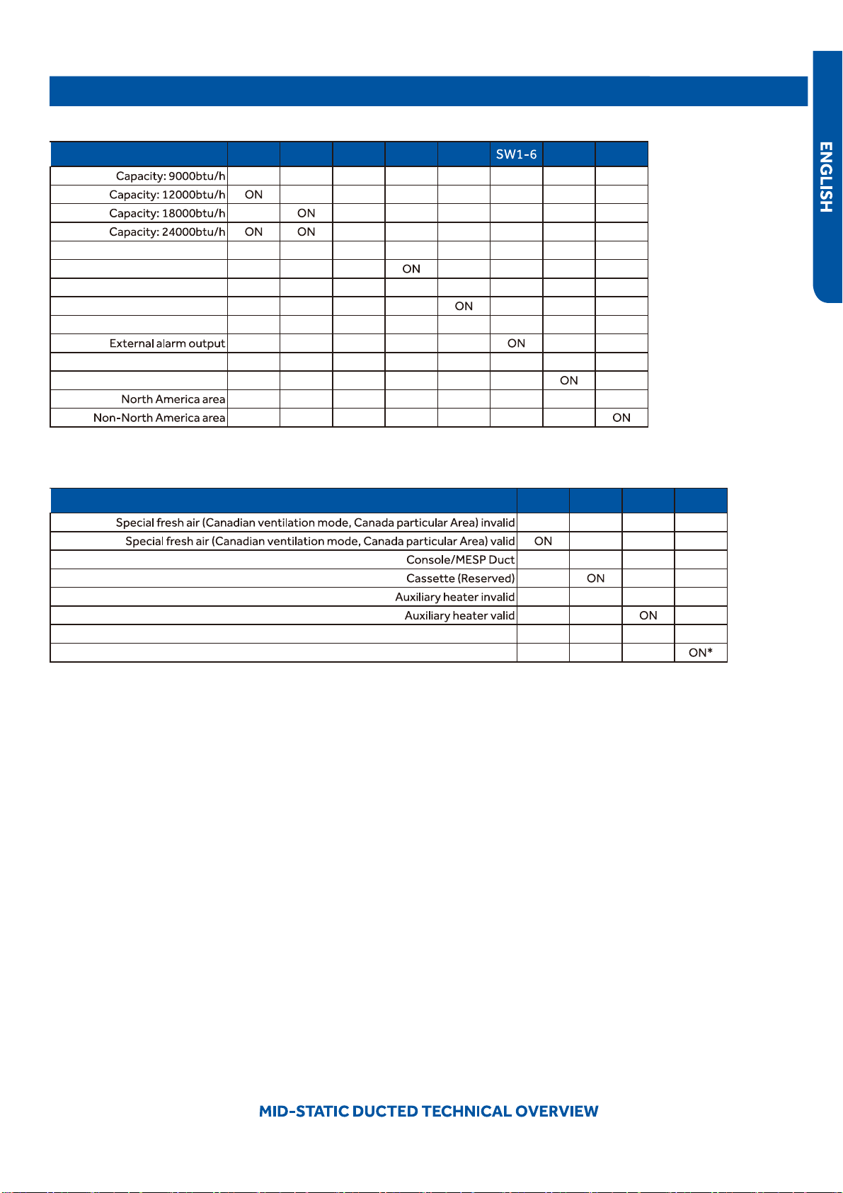
DIP Switch Settings
Description SW1-1 SW1-2 SW1-3 SW1-4 SW1-5
●
SW1-7 SW1-8
OFF OFF OFF --- --- --- --- ---
OFF OFF --- --- --- --- ---
OFF OFF --- --- --- --- ---
OFF --- --- --- --- ---
Room card invalid --- --- --- OFF* --- --- --- ---
●
Room card valid --- --- ---
--- --- --- ---
Heat pump --- --- --- --- OFF* --- --- ---
Cooling only --- --- --- --- --- --- ---
Fresh air valid --- --- --- --- --- OFF* --- ---
--- --- --- --- --- --- ---
Without filter clean warning --- --- --- --- --- --- OFF* ---
With filter clean warning --- --- --- --- --- --- ---
--- --- --- --- --- --- --- OFF*
--- --- --- --- --- --- ---
Description
●
SW3-1 SW3-2 SW3-3 SW3-4
OFF* --- --- ---
--- --- ---
--- OFF* --- ---
--- --- ---
--- --- OFF* ---
●
--- --- ---
ESP grade 0-4 level --- --- --- OFF
ESP grade 0-10 level --- --- ---
SW1 DIP Switch Settings
SW3 DIP Switch Settings
*Factory Default Setting
*Factory Default Setting
PAGE 50
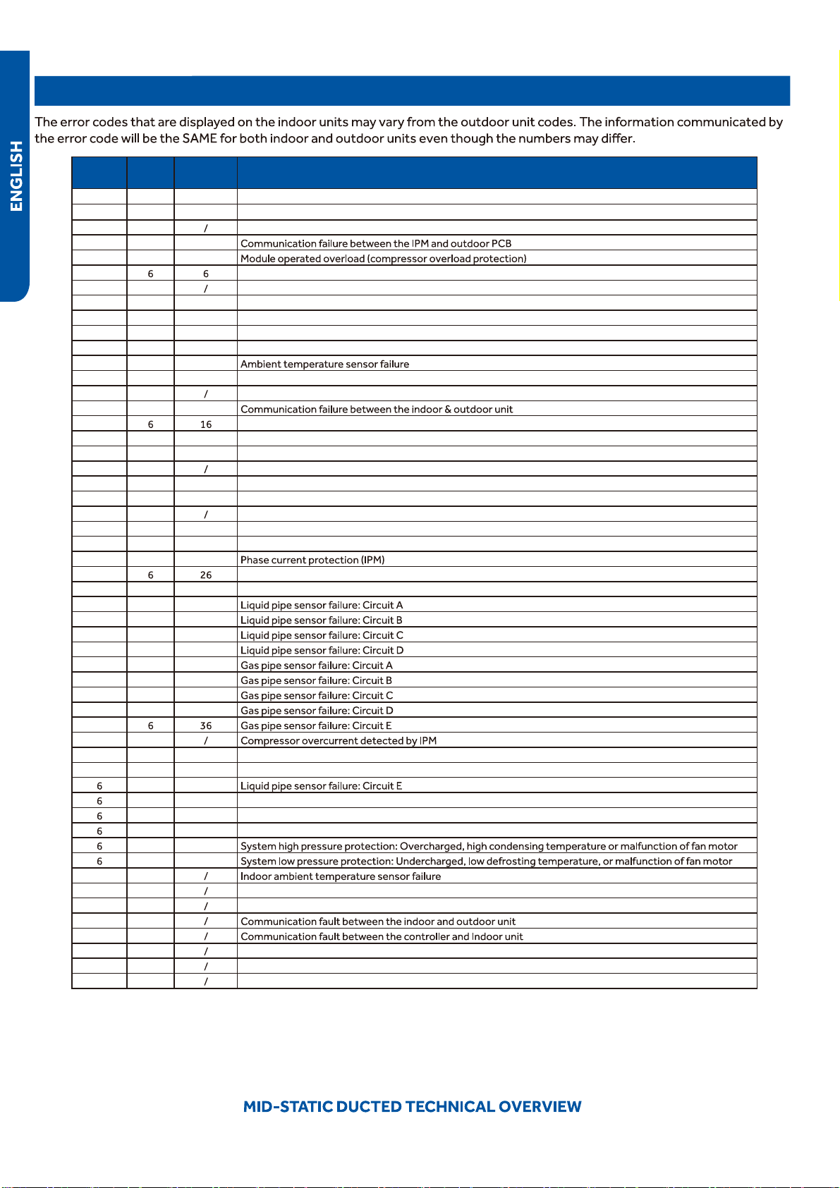
Error Codes
Indoor
LED4
Indoor
LED3
Outdoor
LED
Diagnosis
2 1 1 Outdoor EEPROM failure
2 2 2 IPM overcurrent or short circuit
2 3
Compressor over current during deceleration
2 4 4
2 5 5
2 Module low or high voltage
2 7
Compressor current sampling circuit fault
2 8 8 Overheat protection for discharge temperature
2 9 9 Malfunction of the DC fan motor
3 0 10 Malfunction of defrost temperature sensor
3 1 11 Suction temperature sensor failure
3 2 12
3 3 13 Discharge temperature sensor failure
3 4
PFC circuit loop voltage
3 5 15
3 Lack of refrigerant or discharging
3 7 17 4-way valve switching failure
3 8 18 Loss of synchronism detection
3 9
Low DC or AC voltage
4 0 20 Indoor thermal overload
4 1 21 Indoor coil frosted
●
4 2
PFC circuit loop overcurrent
4 3 23 Module thermal overload
4 4 24 Compressor start failure, over-current
4 5 25
4 MCU reset
●
4 7 27 Module current detect circuit malfunction
4 8 28
4 9 29
5 0 30
5 1 31
5 2 32
5 3 33
5 4 34
5 5 35
5
5 7
5 8 38 Malfunction of module temperature sensor momentary power failure detection
●
5 9 39 Malfunction of condensing temperature sensor
0 40
1 41 Toci temperature sensor failure
2 42 High Pressure switch open
3 43 Low Pressure switch open
4 44
5 45
0 1
0 2 Indoor coil temperature sensor failure
0 4
Indoor PCB EEPROM failure
0 7
0 8
0 12 Drain system malfunction
●
0 13
●
Zero cross signal detected wrong
0 14
Indoor fan motor malfunction
PAGE 51
CONSOLE TECHNICAL OVERVIEW
CONSOLE TECHNICAL OVERVIEW
Table of Contents
Component Overview ...........................................................................................................................................................
Indoor Circuit Board...............................................................................................................................................................
Removing the Filter Cover & Filter ........................................................................................................................................
Front Cover Removal .............................................................................................................................................................
Control Box Removal .............................................................................................................................................................
Board
Replacement ...............................................................................................................................................................
Upper Louver Removal ..........................................................................................................................................................
Lower
Damper Assembly Removal .......................................................................................................................................
Replace Fan Motor .................................................................................................................................................................
Ind
oor Fan Motor Test Procedure .........................................................................................................................................
Testing Temperature Sensors ...............................................................................................................................................
Testing Louver Motors ..........................
................................................................................................................................
Testing
Communication Circuit ............................................................................................................................................
Replacing WiFi Module ...........................................................................................................................................................
USYF09UCDWA
USYF12UCDWA
USYF18UCDWA
PAGE 52
53
53
54
55
55
55
55
55
56
56
56
57
58
58
59
59
60
61
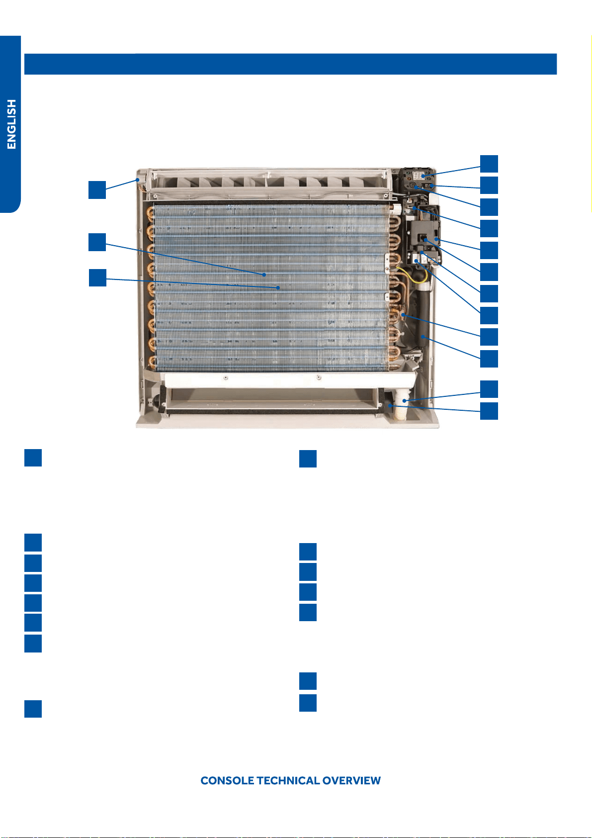
Components
The indoor console unit functions as an evaporator coil during cooling mode, and as a condensing coi
l during heat mode.
Condensate is collected by a drain pan below the coil and condensate is drained directly to the outd
oor or to a secondary
condensate pump via the provided condensate drain line
Console units may be operated with either a wired remote control or the wireless remote control prov
ided with the unit.
Component Overview
1
4
5
6
7
8
13
14
15
9
10
11
12
2
3
Display
The indoor unit display communicates system mode, but
does not display temperatures or diagnostic codes. This
information is indicated on the wired or wireless control.
When servicing a diagnostic error always refer to the
outdoor unit code.
IR Receiver
Power Switch
Lower Damper Control
Control Board Box
Diagnostic Port
Ambient Sensor
The Ambient Temperature Sensor senses room
temperature. This sensor provides room temperature
information to the ECU for calculation of inverter capacity
and temperature control.
WiFi Module
Coil Sensor
The Coil Temperature Sensor senses indoor coil
temperature in the cooling mode and in the heating
mode. This sensor is used for Anti Freezing and Anti
Cold Blow cycles. The sensor also provides critical
temperature information to the ECU that may be used in
frequency adjustments.
Flare Connections
Condensate Drain
Lower Damper Motor
Upper Louver Motor
The louver motor is a stepper type motor that moves
the louver left/right. The motor is controlled by a pulsed
voltage that cannot be measured. If the louver does not
move when it should, check for a bind in the louvers.
Blower Fan (behind coil)
Blower Motor (behind coil)
The indoor unit features a multi-speed blower motor
that will change speed to match the capacity demand
from the outdoor unit. The blower motor is controlled
by both the remote control and by commands from the
outdoor unit ECU
1
13
7
2
14
8
3
15
9
4
10
5
11
6
12
PAGE 53
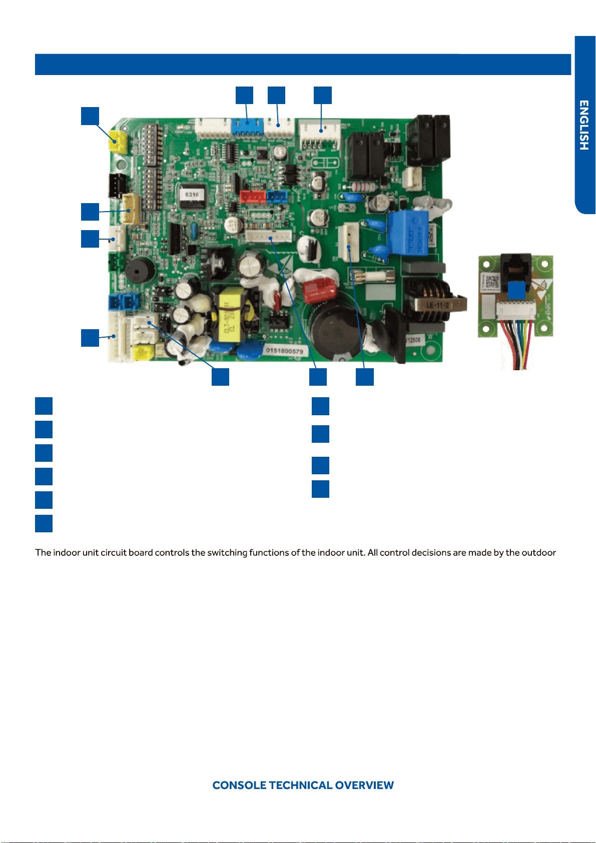
Indoor Circuit Board
Components
1
4
2
5
3
7
10
10
8
6
9
SW2-Damper switch
CN35- Lower damper motor
CN6-DC fan motor
Power supply
CN20-Diagnostic port
CN22- Optional wired controller
6 45
1
7
8
9
5 32
unit ECU. The indoor board has some limited diagnostic capability which will be covered in this man
ual.
The indoor unit Circuit Board communicates with the outdoor unit ECU via a connection at terminal bl
ock screw 3. The data
pulse that sends the communication information can be measured with a voltmeter set to DC voltage ra
nge. From the ground
connection at the terminal block to the number 3 screw, voltage should pulse up and down when data is transmitted.
Line voltage to power the indoor unit is made on terminal block connections 1 and 2. Power connects
from these terminal
connections to CH-3 and CH-4 on the circuit board. If the board does not respond to command and has no display, check for
line voltage at these connections. When power is present at the indoor board, the Display Power Indicator will be lit. The control
board has a replaceable 3.15A 250V fuse that protects against excessive current. If power is presen
t at the board but the board
does not work, check for continuity through the fuse. Replace if the fuse is open.
The indoor unit sensors are connected at plug CN-13. When testing the calibration of these sensors
the wires can be released
from the plug by pressing the tension tab on the side of the plug.
The receiver/display unit, mounted on the front cover of the indoor unit plugs connects to the circuit board at location CN-29.
The blower/fan motor connection is located at plug CN-11.
CN31- Display
CN3-Temperature sensor socket (Tr: ROOM SENSOR,
Tp:PIPE SENSOR)
CN17-WiFi module
RJ45 adapter board
PAGE 54

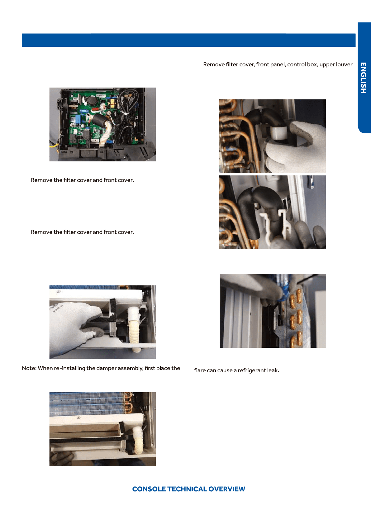
Testing
Removing the Filter Cover & Filter
1. Slide the side latches up to unlock the cover and pull
forward about an inch then lift up.
2.
and removed.
Front Cover Removal
1. Remove the 4 screws that are at the corners of the air
intake opening. Gently open the horizontal louver. Lift up
the top edge of the front cover and then pull forward.
Control Box Removal
1. Remove the screw from the right side of the box cover.
●
2.
module and ambient sensor. And remove the box cover.
●
3. Unplug the three connectors for the fan motor, upper
louver and bottom damper.
4. Remove the ground screw.
5. Remove the mounting screw for the box.
6. The box can now be removed.
Board Replacement
1. Follow the instructions for removing the control box.
2. Remove the cover screw from the bottom of the box, then
remove cover.
PAGE 55
Testing
3. Take note of connection location and carefully remove
each connector.
4. Remove the 2 screws mounting the boar
●
d in the box. They
in diagonal corners from each other.
●
Upper Louver Removal
1.
2. Locate and remove the two scr
●
ews mounting the upper
louver assembly to the case. They are on either end of the
assembly.
Lower Damper Assembly Removal
1.
2. Disconnect the condensate drain.
3. Locate and remove the two screws mounting the damper
assembly to the case.
4. Pull on the right end of the assembly and rotate the
bottom of the assembly outward.
front edge of the condensate drain pan into place then rotate
●
the bottom of the assembly into position.
Replace Fan Motor
1.
and bottom damper.
2. Remove the white plastic strap that hold the line set in
place on the right side of the unit.
3. Locate the locking tabs on the left side of the evaporator
and press them inward and pull the coil forward to remove.
IMPORTANT: Great care should be taken to when performing
this step. Excessively moving the lineset that connects to the
4. Slide the coil to the right to. The coil can now be gently
pulled away from the case. Only move the coil far enough
to access the four screws holding on the fan inlet faring.
PAGE 56
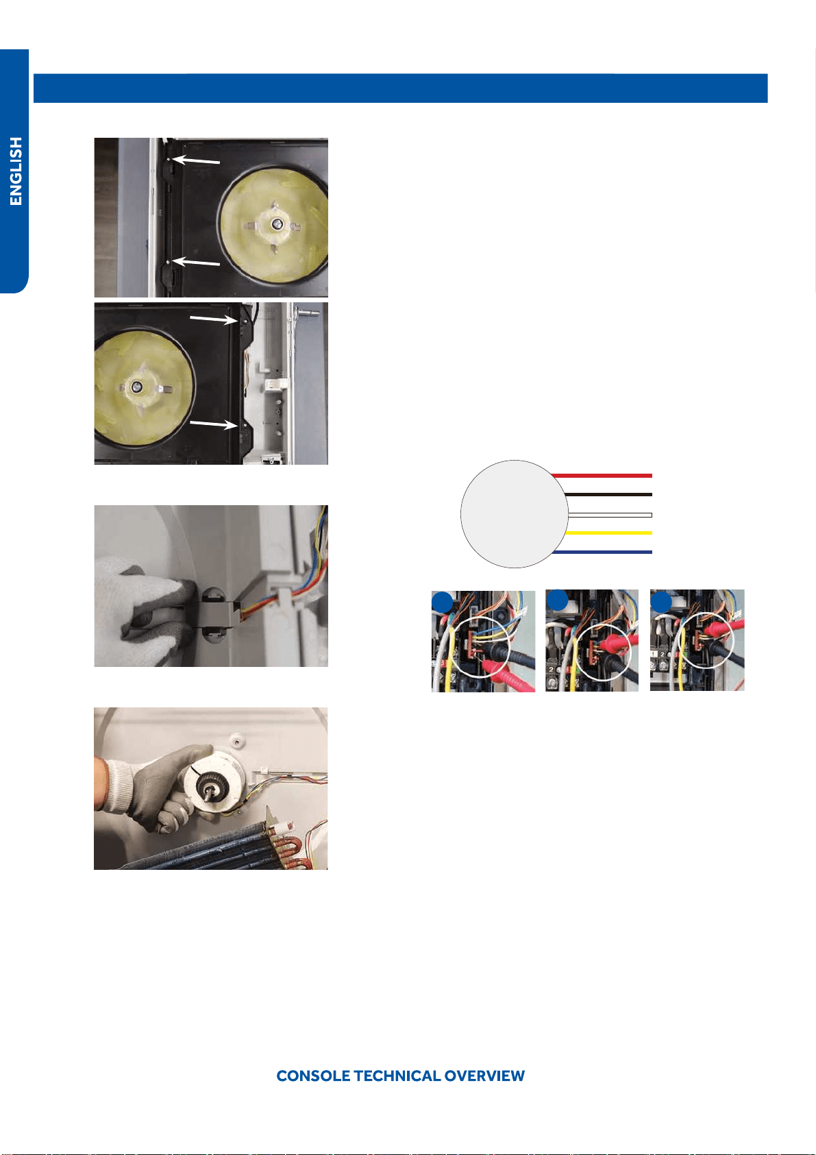
Testing
5. Remove the four screws holding on the fan inlet faring.
6. Remove the wire cover from the back of the case.
●
7. Remove the motor bracket.
●
NOTE: when replacing the motor, the wires must exit from
●
the bottom of the motor to prevent water from entering the
motor.
Indoor Fan Motor Test Procedure
If the indoor fan motor does not run:
1. Disconnect power to the system.
2. Remove the return air cover and access the fan motor
circuit board connection.
3. Reset power and turn the remote control fan command to
Fan On mode.
Motor Test:
1. If the motor doesn’t run, check for 310VDC between Pins 1
and 3. If it is not present, the indoor board is bad. If voltage
is present, continue on.
2. Check the voltage between Pins 3 and 4. The voltage
should be +15VDC. If it is not present, the board is bad. If
voltage is present, continue on.
3. Check for voltage between Pins 3 and 6. If no DC voltage
is present, the board is bad. If voltage is present, change
the motor.
1
2
3
PAGE 57
Testing
Testing Temperature Sensors
The easiest problems to solve will involve codes that are
related to potential failure of temperature sensors. Common
problems may include loose connections, open electrically,
and out of calibration. Checking the condition of the sensors
requires a temperature probe and an ohmmeter.
The Reference Section of this manual contains temperature
●
resistance tables that can be used to check the calibration
of the sensors. The measured resistance must be within the
tolerances printed on the top of the tables.
To test the electrical condition of a temperature sensor
perform the following:
1.
connection plug.
2. Remove the sensor wires form the connection plug by
releasing holding tension on the plugs tension tab.
3. Use an ohmmeter to test the electrical resistance of the
sensor.
4. Measure the air temperature near the sensor and compare
the required resistance against measured resistance.
(See chart in reference section) If the sensor is within
calibration, the sensor is good. If the sensor is out of
calibration, replace the sensor. (Tube Sensors should be
removed from socket and exposed to air temperature
during test.)
2
4
Tp
Tr
To Outdoor Unit
L2
L1
CN22(22-1)
CN31
Main control board
Swing motor
for lower
louver
Swing motor
for upper
louver
CN10
CN3
CN17
SW2
CN16
CN16-1
W
B
W
BL
BL
W
W
W
YL
BL
W
W
To RJ45 DEVICE
Testing Louver Motors
If the louver does not operate with command from the remote
control, either the indoor board is bad, or the louver motor
is defective. It is more likely the motor is defective than the
board. (Make sure the louver assembly is not binding and
keeping the vanes from moving.)
1. Remove power from the unit and remove the indoor unit
cover.
2. Access the circuit board.
3. Identify the inoperable louver motor on the schematic
drawing below and disconnect the plug from the circuit
board.
4. Use an Ohmmeter to test the electrical continuity of the
louver motor windings. The proper resistance for each
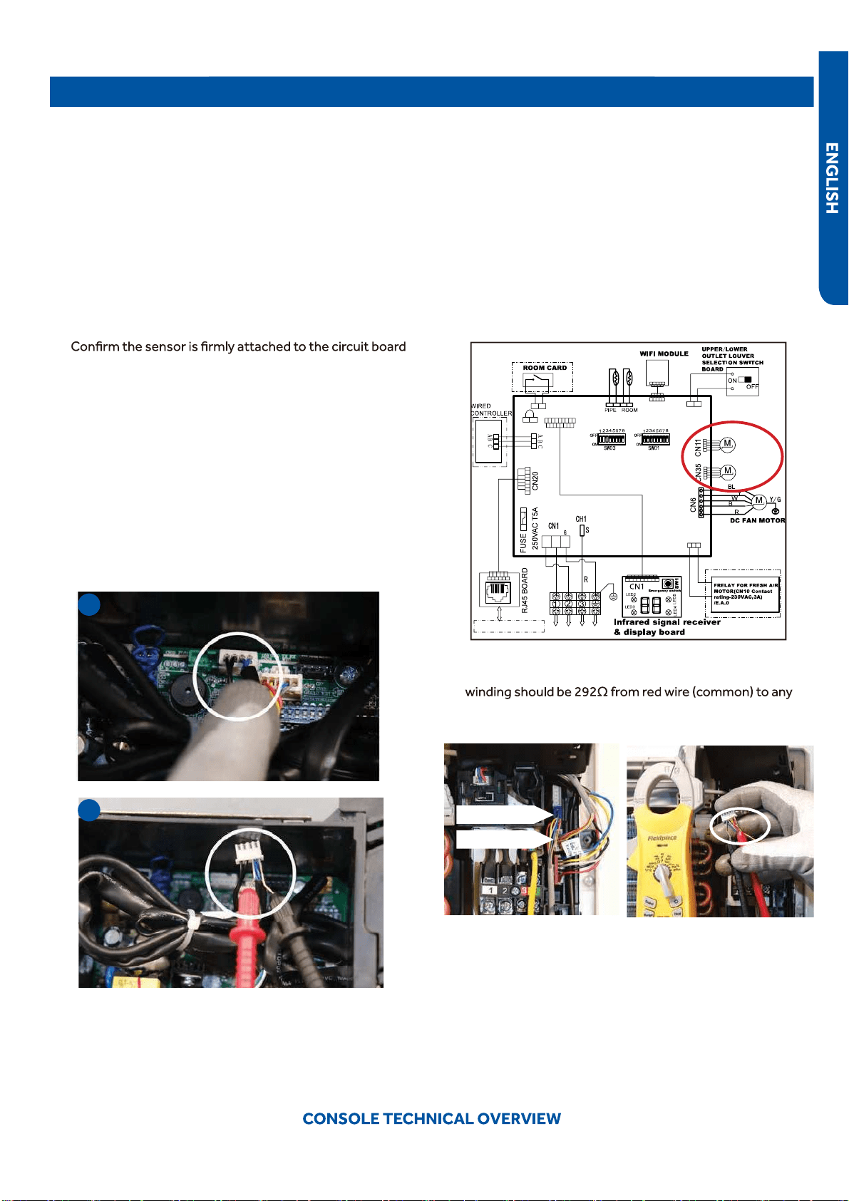
other wire.. If the motor winding resistance is erratic or
shows open, the motor is defective. Replace the motor.
5.
●
If the motor checks out good, replace the indoor control
board.
●
Upper Louver
Lower Louver
PAGE 58
Testing
Testing Communication Circuit
If an Error E7 occurs, perform the following test to determine
if the indoor control board is functioning properly to send data
to the outdoor unit.
Perform this test with the unit powered and all wiring
connected between indoor and outdoor unit.
Make sure all wiring between the indoor and outdoor unit
are correct. There should no splices between the indoor and
outdoor unit wiring connecting terminals 1 or 3. Make sure
wiring is correct, before performing this test.
●
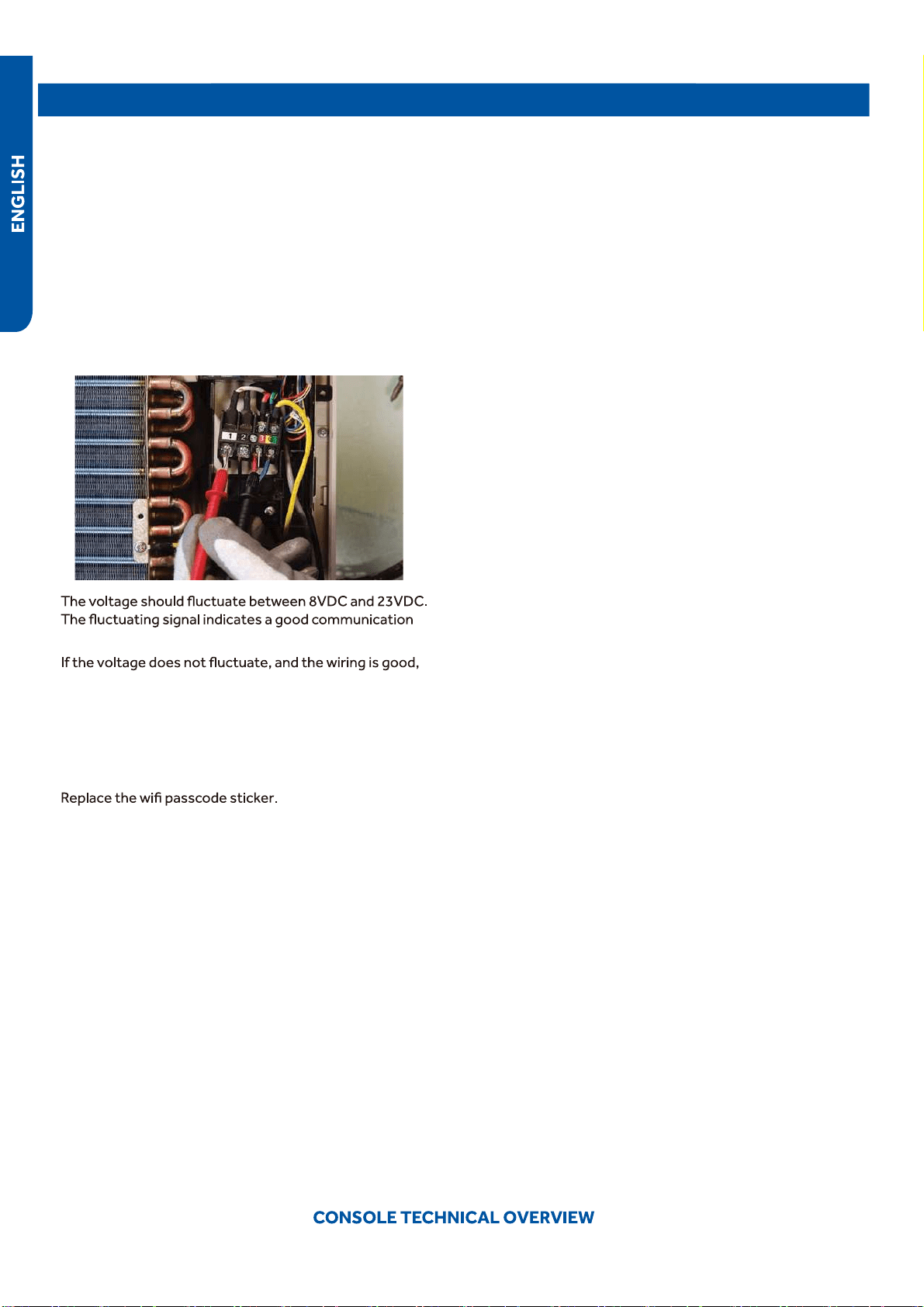
1. Measure the DC voltage between terminals 1 and 3 on the
indoor terminal block.
2.
path.
3.
the indoor board is defective.
●
Replacing WiFi Module
1. Unplug existing WiFi module.
●
2. Insert new WiFi module.
3.
4. Pair the unit to account.
PAGE 59
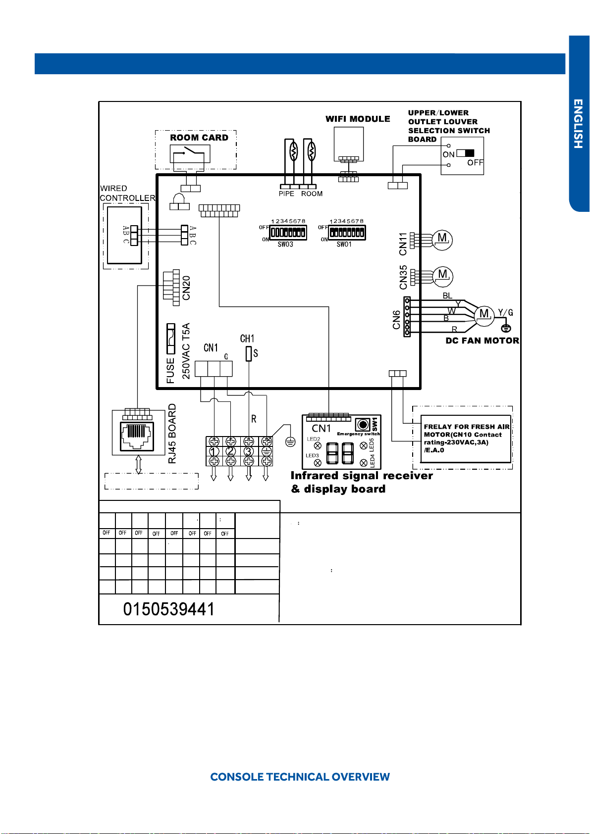
Wiring Diagram/DIP Switch Settings
USYF09UCDWA1
●
Note
1.Dashed parts are optional.
2.Please refer to the technical service manual for detailed explanations
of DIP switches.
3.Do not change the DIP switches setting without technical support
4.Abbreviation
R-red ,B-black,BL-blue,W-white,Y/G-yellow/green,
TEMP.-temperature, E.A.O-exrernal alarm output,Tr-indoor unit
room temperature sensor ,Tp-indoor unit pipe temperature sensor (coil
●
temperature sensor)
Tp
Tr
SW1-1
OFF
OFF
SW1-2
OFF
OFF OFF
OFF
OFF
OFF
OFF
OFF
OFF OFF
OFF
OFF
OFF
ON
OFF
OFF OFF
OFF
OFF
OFFOFF
ON
SW1-3
SW1-4
SW1-5 SW1-6
SW1-7 SW1-8
To Outdoor Unit
All Console
default
MODEL
DIP switches factory default setting
L2
L1
CN22(22-1)
CN31
Main control board
Swing motor
for lower
louver
Swing motor
for upper
louver
CN10
CN3
CN17
SW2
CN16
CN16-1
W
B
W
BL
BL
W
W
W
YL
BL
W
W
To RJ45 DEVICE
SW3-1
SW3-2 SW3-3
SW3-4
SW3-5 SW3-6
SW3-7 SW3-8
USYF12UCDWA1
USYF18UCDWA1
PAGE 60
Error Codes
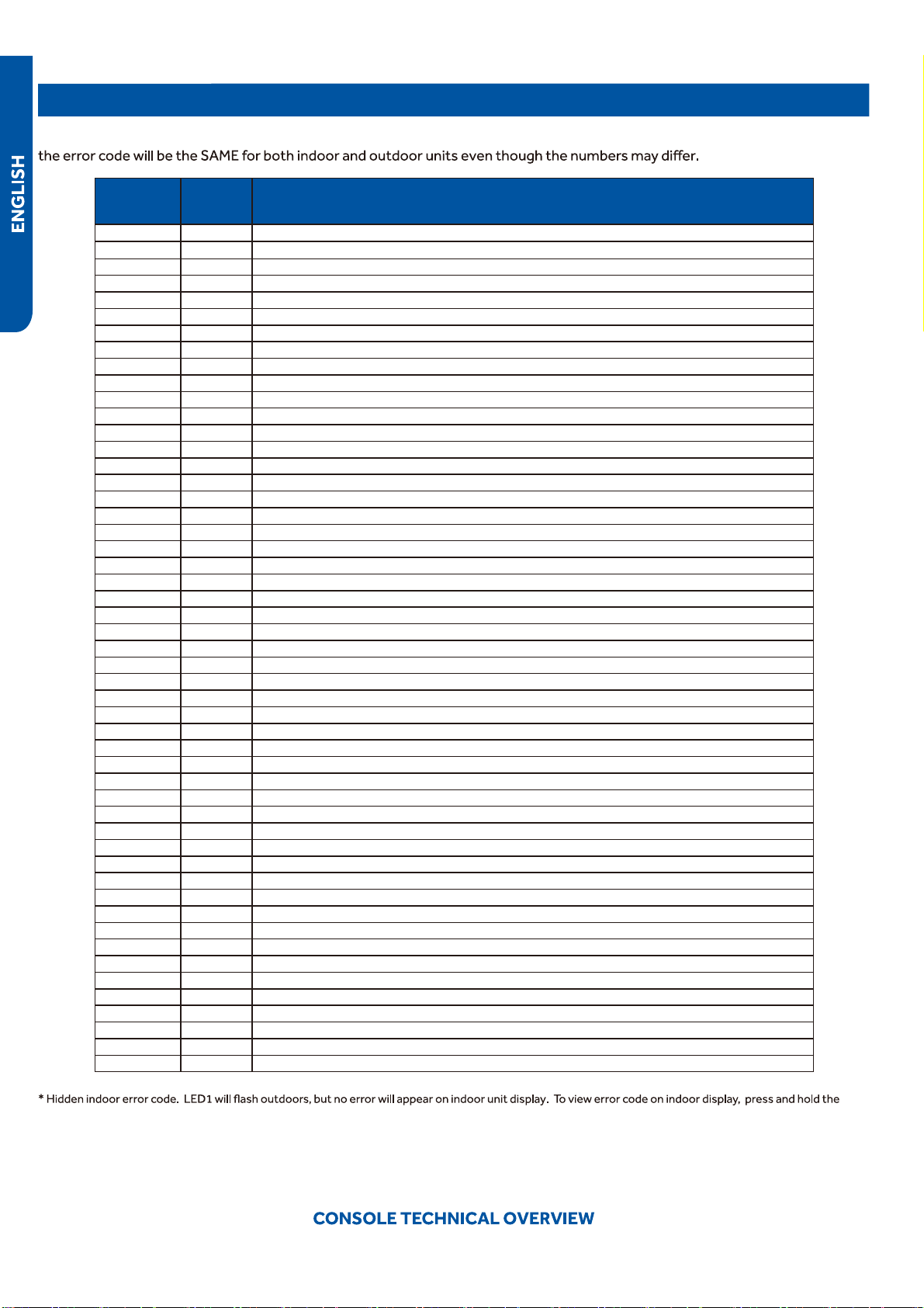
The error codes that are displayed on the indoor units may vary from the outdoor unit codes. The information communicated by
Indoor
Display
Outdoor
LED
Diagnosis
F12 1 Outdoor EEPROM failure
F1 2 IPM overcurrent or short circuit
F22 / Outdoor alternating current, over current protection
F3 4 Communication failure between the IPM and outdoor PCB
F20* 5 Module operated overload (compressor overload protection)
F19* 6 Module low or high voltage
F27 / Compressor current sampling circuit fault
F4 8 Overheat protection for discharge temperature
●
F8* 9 Malfunction of the DC fan motor
F21 10 Malfunction of defrost temperature sensor
F7 11 Suction temperature sensor failure
F6 12 Ambient temperature sensor failure
F25 13 Discharge temperature sensor failure
F30* / High outdoor suction temperature
E7 15 Communication failure between the indoor & outdoor unit
F13* 16 Lack of refrigerant or discharging
F14* 17 4-way valve switching failure
F11 18 Loss of synchronism detection
F28 / Position detection circuit fault of compressor
F15* / Terminal block temp too high
F5* 23 Module thermal overload
F2* 24 Compressor start failure, over-current
F23 25 Phase current protection (IPM)
F9 26 MCU reset
F24 27 Module current detect circuit malfunction
F10 28 Liquid pipe sensor failure: Circuit A
F16 29 Liquid pipe sensor failure: Circuit B
F17 30 Liquid pipe sensor failure: Circuit C
●
F18 31 Liquid pipe sensor failure: Circuit D
F29 32 Gas pipe sensor failure: Circuit A
F30 33 Gas pipe sensor failure: Circuit B
F31 34 Gas pipe sensor failure: Circuit C
F32 35 Gas pipe sensor failure: Circuit D
F26 36 Gas pipe sensor failure: Circuit E
F34 / Outdoor pipe temperature protection in cooling mode
F35 38 Malfunction of module temperature sensor momentary power failure detection
F36 39 Malfunction of condensing temperature sensor
F33 40 Liquid pipe sensor failure: Circuit E
F38 41 Toci temperature sensor failure
F39 42 High Pressure switch open
●
F40 43 Low Pressure switch open
F41 44 System high pressure protection: Overcharged, high condensing temperature or malfunction of fan motor
F42
●
45 System low pressure protection: Undercharged, low defrosting temperature, or malfunction of fan motor
F43 / Incorrect match between indoor & outdoor
E1 / Indoor ambient temperature sensor failure
E2 / Indoor coil temperature sensor failure
E4 / Indoor PCB EEPROM failure
E8 / Communication fault between the controller and Indoor unit
E12 / Drain system malfunction
E13 / C1 / Zero cross signal detected wrong
E14 / Indoor fan motor malfunction
Emergency button for 15 seconds.
PAGE 61
63
63
64
66
66
63
63
63
63
63
64
64
64
64
64
65
65
65
65
65
65
65
66
66
66
66
66
66
67
67
67
67
67
68
68
68
69
69
69
69
69
69
69
SEQUENCE of OPERATION
System Power
The 230 Volt AC power for the system connects to terminals
1(N), 2(L), and ground of the outdoor unit terminal block. This
terminal block also has terminals to connect power to the
indoor unit.
The voltage readings between terminals 1(N) and ground, and
●
terminals 2(L) and ground should be 120 VAC. The voltage
reading between terminals 1(N) and 2(L) should be 230 VAC.
●
One additional connection on the terminal block (3) is for the
communication wire between the indoor and outdoor units.
NOTE: Mis-wiring of these connections may cause improper
operation or damage to system components.
Cool Mode
Overview
The temperature control range in cooling mode is 60°F - 86°F.
The temperature set by the remote control and the indoor
unit ambient temperature sensor will determine if a call for
cooling is needed. If a call for
communicated from the indoor unit to the outdoor unit. The
indoor unit louver will open using a stepper motor, and the
●
indoor fan will operate at the speed last set. The outdoor unit
will determine the position of the EEV and speed frequency
of the compressor. There can be a delay of up to 3 minutes
before the outdoor unit fan and compressor start.
●
The speed of the indoor fan can be controlled manually by
the user or automatically by the system. The speed can be
●
changed between LOW, MEDIUM, and HIGH.
The predetermined conditions for automatic control are
as follows:
(Tr= room temperature Ts= set temperature)
High Speed: Tr
Ts + 5.4°F
Medium Speed: Ts + 1.8°F
Tr < Ts + 5.4°F
Low Speed: Tr
Ts + 1.8°F or when the sensor is
There will be a 2 second delay when manually controlling the
speed.
The outdoor unit temperature sensors: outdoor ambient,
defrost, suction line, and compressor discharge, used in
conjunction with the indoor temperature sensors, indoor
ambient and coil, provide information to the outdoor control
board to monitor the system and regulate the frequency of
the compressor, the EEV, and outdoor fan speed, to
achieve
the desired room temperature.
followed by the outdoor fan. The indoor unit fan
will continue to run.
If the system detects a malfunction, it may shut down or
show an error code. This code will be shown on the indoor di-
Indoor Unit
To enter the cool mode, point the infrared remote control at
the indoor unit and press the power button, then press the
COOL mode button if not already set to cool mode.
The signals received by the infrared receiver are relayed to
the main board of the indoor unit to turn the system on and
set it to cool mode.
The indoor will illuminate the display, indicating
the set temperature and current status of the unit.
The to open the louver to
either a stationary position, or one of several oscillating
modes.
As the louver opens, the indoor unit main board will power up
the indoor fan motor, operating the fan at the speed last set.
The indoor fan motor has a feedback circuit which provides
the indoor unit main board with information for controlling
the speed of the fan motor.
Temperature Sensors
The indoor unit has two sensors that provide temperature
information to the main board. The sensors: an indoor ambi-
ent temperature sensor, and pipe temperature sensor, are
used for controlling the system during cool mode.
The resistance values of the sensors will vary with tempera-
ture. The resistance to temperature values can be found
to the sensor
being checked.
Communication
The indoor and outdoor unit main boards communicate via a
digital signal on the wire connected to terminal 3 of each unit.
A splice or break in this wire will cause a communication error.
When a command is received from the remote control, the
indoor unit main board communicates with the outdoor unit
main board to perform the requested function.
Outdoor Unit
Upon a request for cooling, the outdoor unit main board ap-
plies power to the outdoor fan motor
and compressor. Depending on system cycling, there may
be up to a 3 minute wait period before the compressor and
outdoor fan start.
WARNING: Do not measure compressor voltages as damage
to the meter may result.
If the room temperature is less than the set temperature,
yet higher than 2°F below the set temperature, the system
will adjust the speed of the compressor automatically.
>=
PAGE 63
SEQUENCE of OPERATION
The outdoor unit main board also controls the position of the
EEV (Electronic Expansion Valve)
to regulate the
ow of refrigerant to the indoor unit evapora-
tor coil.
Temperature Sensors
●
Call to Terminate Cooling
●
The system will terminate cooling when the indoor ambient
temperature sensor is equal to or lower than 2°F of the room
set temperature. The indoor control board
●
will communicate
to the outdoor control board to de-energize the compressor.
The outdoor fan will run for 60 seconds before stopping.
The indoor fan motor and louver
●
will continue operating after
cooling has been terminated.
To stop cool mode, press the power button to turn the sys-
tem o
, or change to another mode.
Freeze Protection Function
Heat Mode
●
Overview
The temperature control range in heating mode is 60°F - 86°F.
The temperature set by the remote control and the indoor
unit ambient temperature sensor will determine if a call for
heat is needed. If a call for heat is justi
ed, a temperature
compensation adjustment is automatically added to the
operating parameter and the call is communicated from the
indoor unit to the outdoor unit.
The indoor unit louver will open using a stepper motor. The
indoor fan will not operate at this time.
The outdoor unit will shift the 4-way valve to the heat mode
position and determine the position of the EEV and speed
(frequency) of the compressor. There can be a delay of up
to 3 minutes before the outdoor unit fan and compressor
start.
(Tr = room temperature Ts = set temperature)
If Tr
Ts, the outdoor unit will operate and the indoor fan
operates in cold air prevention function
If Tr > Ts, the outdoor unit turns o
and the indoor fan oper-
ates at heat residue sending mode.
If Tr < Ts, the outdoor unit will restart and the indoor fan
operates in cold air proof mode.
The speed of the indoor fan can be controlled manually by
the user or automatically by the system. The speed can be
changed between HIGH, MEDIUM, and LOW. The predeter-
mined conditions for automatic control are as follows:
High Speed: Tr < Ts
Medium Speed: Ts
Tr Ts + 4°F
Low Speed: Tr > Ts + 4°F
When the indoor fan is running in automatic mode when the
speed switches from high to low, the indoor fan will maintain
high speed for a period of 3 minutes before switching to low
speed.
Four temperature sensors located in the outdoor unit provide
temperature information to the outdoor unit main board for
control of the system during cool mode.
The outdoor ambient temperature sensor provides the
temperature of the air drawn into the condenser coil
The defrost temperature sensor provides the temperature
sensed at the output of the condenser coil.
The suction line temperature sensor provides the temperature
sensed at the incoming suction line pipe.
The compressor discharge sensor provides the temperature
sensed at the discharge pipe of the compressor.
Cold Air Proof Operation
At initial start of heat mode, indoor blower will not be turned
on immediately until indoor coil temperature senses a minimum
temperature. This period usually takes 30 seconds to 3
minutes depending on the outdoor temperature.
Set speed
Low speed
Light speed
Fan/off
Keep the high
speed. The fan
doesn’t stop
4 minutes after the indoor fan starts, the light or low speed
When the compressor operates continuously for 10 seconds
and the temperature of the indoor coil has been below 32°F
for 10 seconds, the compressor will stop. The indoor unit fan
will continue to operate. When the temperature of the indoor
coil rises to 45°F for more than 3 minutes the compressor will
restart and the system will continue functioning.
will swich to the set speed.
Residual heat sending: the indoor fan will operate on low
speed until the coil temperature reaches 77 degrees.
The outdoor unit temperature sensors: outdoor ambient,
defrost, suction line, and compressor discharge, used in
conjunction with the indoor coil and room temperature
77°F
°F
95
99
°F
PAGE 64
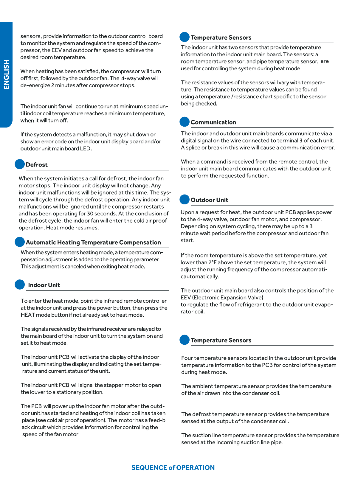
PAGE 65

PAGE 66
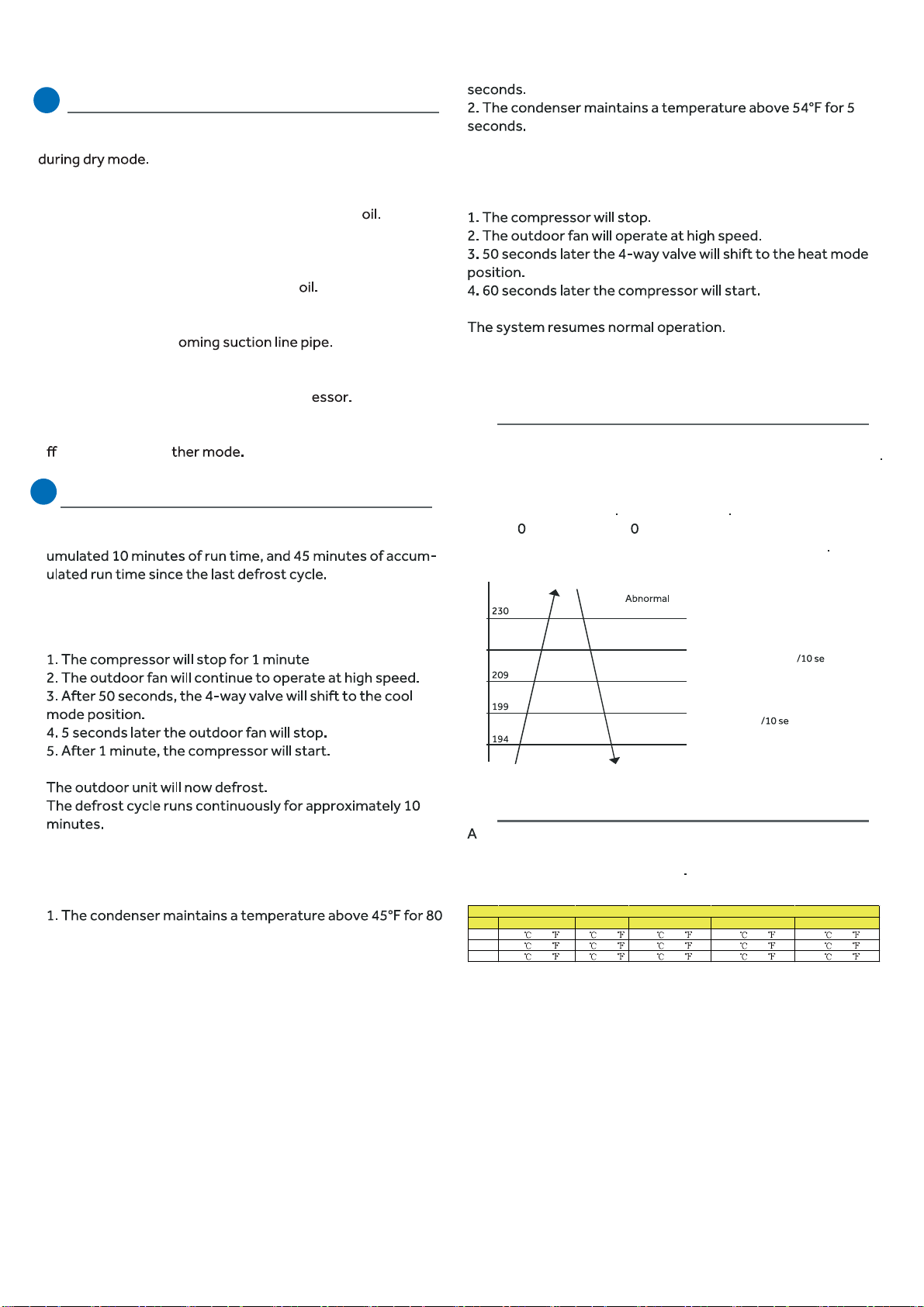
SEQUENCE of OPERATION
Temperature Sensors
To enter the defrost mode, the compressor must have acc-
●
When the defrost cycle begins, the following conditions take
●
place:
The system will exit the defrost cycle if any of the following
●
conditions are met:
●
Upon exiting the defrost cycle, the following conditions will
take place:
Protection Functions
1. Compressor High Temperature
The compressor discharge pipe sensor (exhaust temp)
senses the temperature of the refrigerant exiting the compressor
The sensed temperature received from the sensor
by the control circuitry will cause the compressor frequency
to increase or decrease
(see chart below) If a temperature
of >= 23
°F is sensed for 2 seconds, an exhaust overheating
protection error code will be indicated at the outdoor unit
stop
Decreasing the frequency rapidly (1HZ/1second)
TTC (°F)
°F
212°F
°F
°F
°F
Decreasing the frequency slowly (1HZ conds)
The frequency doesn’t change
Increasing the frequency (1HZ conds)
Increasing the frequency (1HZ/1second)
2. Overheating Protection for Indoor Unit
sensor monitors coil temperature in both heating and cooling
modes, and causes the compressor to speed up, slow down, or
stop, according to the chart below
Four temperature sensors located in the outdoor unit provide
information to the outdoor unit PCB for control of the system
The outdoor ambient temperature sensor provides the
temperature of the air drawn into the condenser c
The defrost temperature sensor provides the temperature
sensed at the output of the condenser c
The suction line temperature sensor provides the tempera-
ture sensed at the inc
The compressor discharge sensor provides the temperature
sensed at the discharge pipe of the compr
To stop dry mode, press the power button to turn the system
o
, or change to ano
Defrost Operation
Model Increasing slowly Holds value Decreasing slowly Decreasing rapidly Compressor stops
09K 40
/104 52 /126 57 /135 60 /140 63 /145
12K 40 /104 52 /126 57 /135 60 /140 63 /145
18K 40 /104 52 /126 57 /135 60 /140 63 /145
Overheating Protection for Indoor Unit
PAGE 67
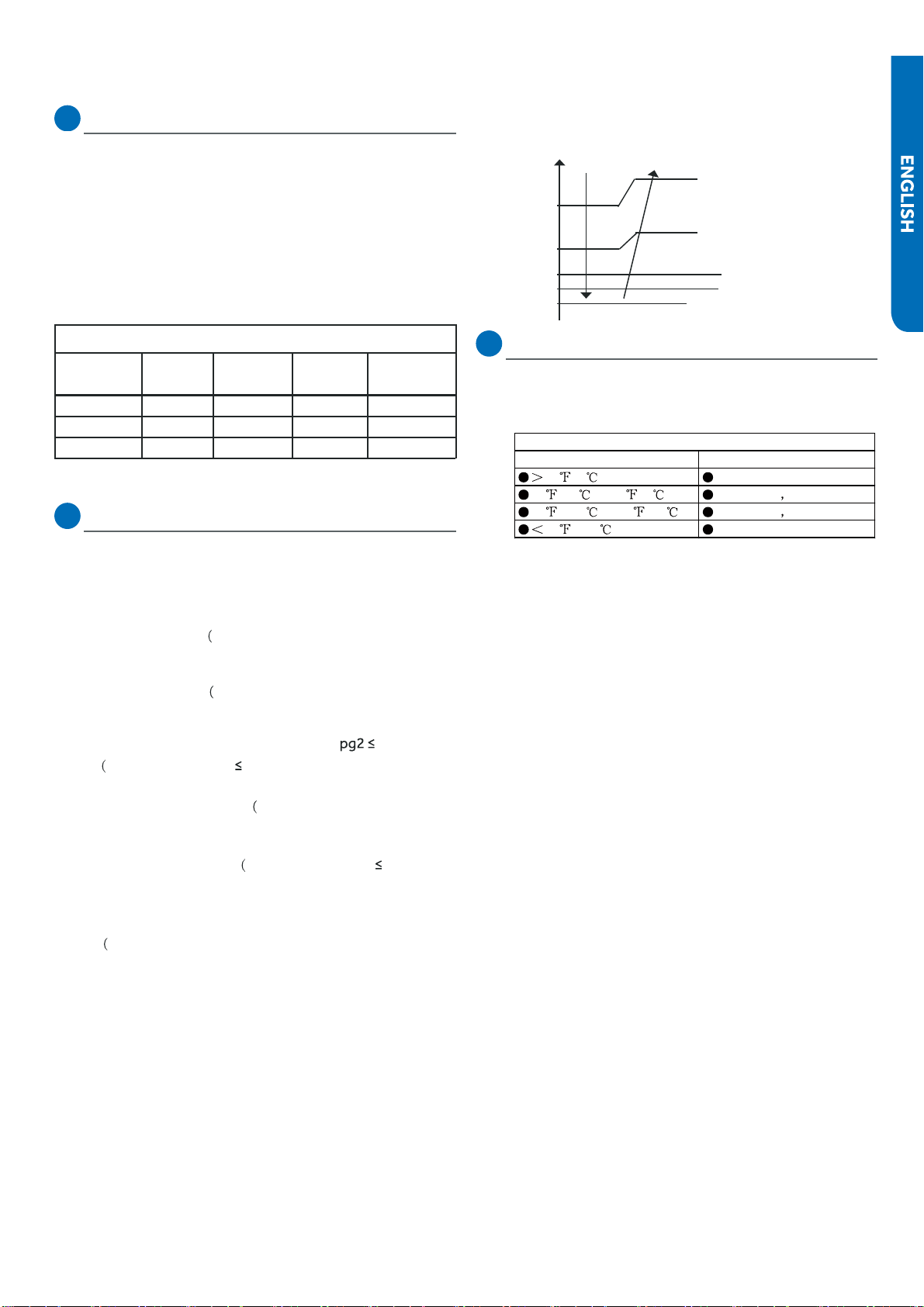
SEQUENCE of OPERATION
52°F //
48°F //
43°F
Decreasing slowly
●
Decreasing rapidly
Stop
Keeping
the
frequency
Increasing slowly
32°F
Tpg1=37°F
Tpg2=41°F
Tpg3=45°F
Tpg4=48°F
3. Compressor Over-current Protection
If the current draw of the compressor at start-up is greater
than the values listed on the chart below for approximately 3
seconds, the compressor will stop.
After 3 minutes the
compressor will restart. If the over-current condition occurs
3 times in 20 minutes, the system will lock-out, and a code
will be indicated at the outdoor unit. It will be necessary to
remove power to the system to reset the lock-out condi-
tion.
Model
Holds
value
Decrease
1Hz/10s
Decrease
1Hz/s
Over-current
point
09K
12A
10A
●
9A8A
12K
16A
15A14A13A
18K
18A
17A
●
16A15A
4. Anti-freeze Protection of the Indoor Coil
●
The temperature sensed by the coil
●
sensor is used to dete-
rmine at what speed the compressor is to run to avoid the
coil temperature being too cold.
Tpg_indoor: indoor unit pipe sensor temperature
When Min(Tpg_indoor ,
Tpg_indoor+Ts)/2) <
Tpg1, the freq-
uency of the compressor decreases at the rate of 1HZ / 1
When Tpg_indoor begins to rise again, and T
Tpg3, the frequency of the
compressor does not change.
When Tpg3 <
frequency of the compressor increases at the rate of 1HZ / 10
second
Example: if
32°F sust-
ains for 2 minutes, the outdoor unit will stop and indicate an
underload malfunction code at the outdoor unit. The com-
pressor stops for a minimum of 3 minutes. When Min(Tpg_
indoor , Tpg_indoor+Ts)/2)>Tpg4, the compressor will
restart
5. Base Pan Heater
To keep condensate water from freezing inside the cabinet,
a base pan heater is installed at the factory. Refer to the
chart below for the operating parameters.
Ts: outdoor unit Suction Line sensor temperature
second.
When Min(Tpg_indoor , Tpg_indoor+Ts)/2) <
Tpg2, the freq-
uency of the compressor decreases at the rate of 1HZ / 10
Min(Tpg_i-
ndoor ,
Tpg_indoor+Ts)/2)
Min(Tpg_indoor ,
Tpg_indoor+Ts)/2) <Tpg4, the
second.
Min(Tpg_indoor , Tpg_indoor+Ts)/2)
Current Overload Prodection
Outdoor Temperature Pan Heater
37 /3 OFF
28 /-2 to 34 /1 OFF 20min ON 10min
10 /-12 to 25 /-4 OFF 15min ON 15min
10 /-12 ON
Pan Heater Logic
PAGE 68
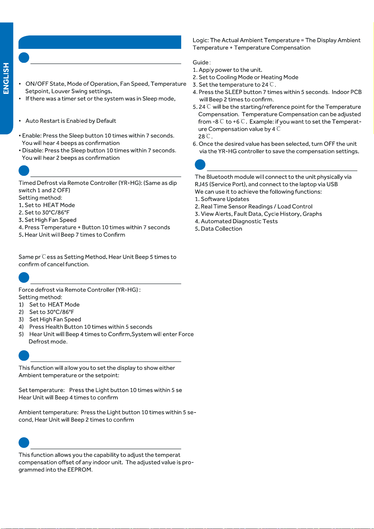
SEQUENCE OF OPERATION
[This page intentionally left blank.]
●
SEQUENCE of OPERATION
Special Functions
Auto Restart
When this is enabled, the following functions will automatically
resumes after a power loss:
they will be canceled upon restart
Wired Controller:
Wireless Controller:
Timed Defrost
Cancel method:
Demand Defrost
Indoor Temperature Display
●
the
cond,
●
Temperature Compensation
●
ure
, then set the temperature to
RJ45
PAGE 69
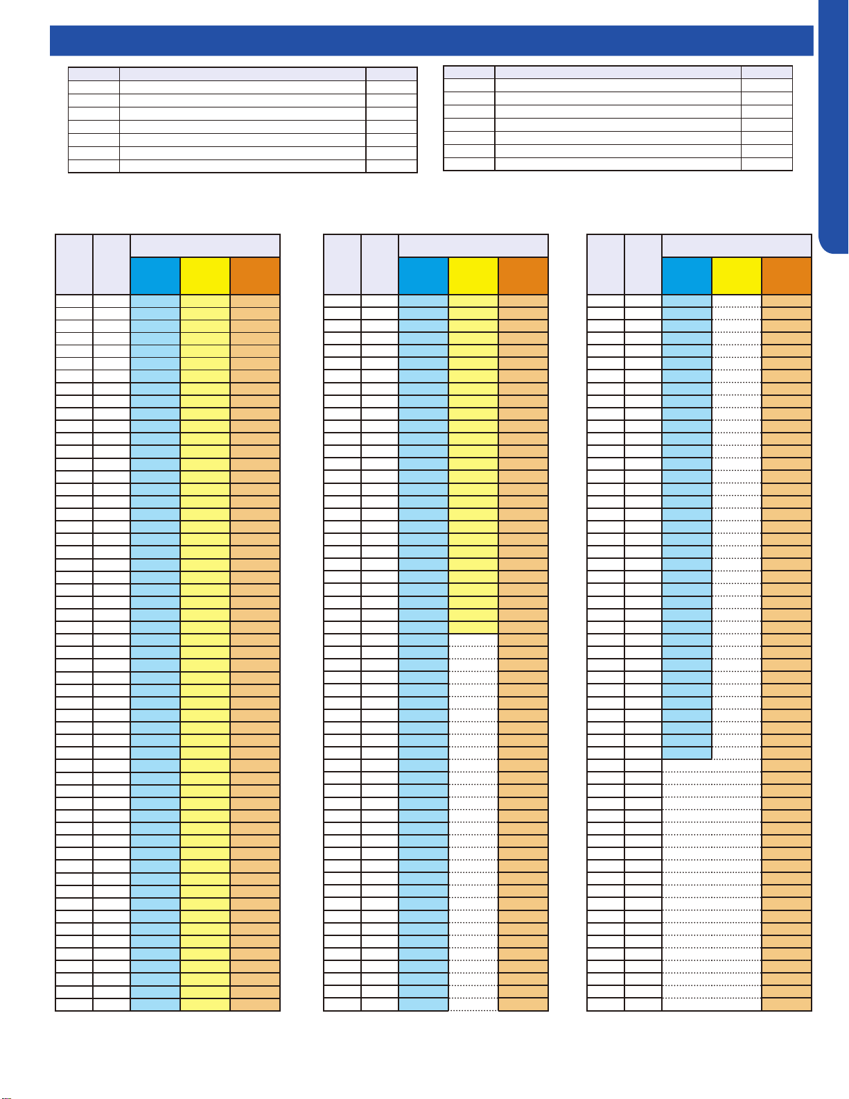
TROUBLESHOOTING & REFERENCES
ENGLISH
Topic Title
Resistance Chart / Sensor Denitions
Abbr. Definition Type
tAo Temperature of outdoor ambient 10K
tc Temperature of outdoor condenser 10K
td Temperature of outdoor discharge 50K
tE Temperature of outdoor defrost 10K
tS Temperature of outdoor suction 10K
tdr Temperature of compressor driver module 10K
Idr Current of the compressor 10K
Abbr. Definition Type
tAI Temperature of indoor ambient 10K
TCI Temperature of indoor condenser 10K
Toci Hot Gas Leaving the 4-Way Valve 10K
Tc2 EEV Liquid Sensor 10K
Tc1 EEV Gas Sensor 10K
Tm Module Temp Sensor 10K
TAI Temperature of indoor ambient (9K/12K Tempo & All CAC) 23K
10K Sensors: Ambient (all except ducted, cassette, and 9K-12K Tempo) suction, gas, defrost, and pipe sensors.
23K Sensors: Ambient sensors for ducted, cassette, and 9K-12K Tempo
50K Sensors: Discharge sensors
°F °C
Normal (KΩ)
10K
SENSORS
23K
SENSORS
50K
SENSORS
-22 -30 147.95 513.115 12061.74
-20.2 -29 139.56 478.894 11267.87
-18.4 -28 131.70 447.408 10531.37
-16.6 -27 124.34 418.379 9847.72
-14.8 -26 117.44 391.564 9212.81
-13 -25 110.96 366.751 8622.85
-11.2 -24 104.89 343.754 8074.38
-9.4 -23 99.19 322.407 7564.22
-7.6 -22 93.83 302.567 7089.47
-5.8 -21 88.80 284.105 6647.45
-4 -20 84.07 266.905 6235.71
-2.2 -19 79.62 250.866 5851.99
-0.4 -18 75.44 235.895 5494.21
1.4 -17 71.50 221.911 5160.46
3.2 -16 67.79 208.838 4849.00
5 -15 64.30 196.609 4558.19
6.8 -14 61.01 185.163 4286.55
8.6 -13 57.91 174.443 4032.71
10.4 -12 54.99 164.399 3795.39
12.2 -11 52.23 154.983 3573.43
14 -10 49.62 146.153 3365.73
15.8 -9 47.17 137.87 3171.31
17.6 -8 44.85 130.096 2989.25
19.4 -7 42.65 122.799 2818.67
21.2 -6 40.58 115.946 2658.81
23 -5 38.62 109.51 2508.91
24.8 -4 36.77 103.462 2368.32
26.6 -3 35.01 97.779 2236.39
28.4 -2 33.36 92.437 2112.55
30.2 -1 31.78 87.415 1996.25
32 0 30.30 82.691 1887.00
33.8 1 28.89 78.248 1784.33
35.6 2 27.55 74.067 1687.81
37.4 3 26.29 70.133 1597.04
39.2 4 25.09 66.43 1511.65
41 5 23.95 62.943 1431.28
42.8 6 22.87 59.659 1355.62
44.6 7 21.84 56.566 1284.36
46.4 8 20.87 53.651 1217.23
48.2 9 19.94 50.904 1153.96
50 10 19.06 48.314 1094.32
51.8 11 18.23 45.872 1038.07
53.6 12 17.43 43.569 985.01
55.4 13 16.68 41.395 934.94
57.2 14 15.96 39.343 887.68
59 15 15.28 37.406 843.05
60.8 16 14.63 35.577 800.89
62.6 17 14.01 33.848 761.06
64.4 18 13.42 32.215 723.41
66.2 19 12.86 30.671 687.82
68 20 12.32 29.21 654.16
69.8 21 11.81 27.828 622.32
71.6 22 11.33 26.521 592.18
73.4 23 10.86 25.283 563.66
75.2 24 10.42 24.111 536.65
77 25 10.00 23 511.08
78.8 26 9.60 21.947 486.94
°F °C
Normal (KΩ)
10K
SENSORS
23K
SENSORS
50K
SENSORS
80.6 27 9.21 20.949 464.05
82.4 28 8.85 20.003 442.35
84.2 29 8.50 19.104 421.77
86 30 8.16 18.252 402.24
87.8 31 7.84 17.442 383.72
89.6 32 7.54 16.674 366.13
91.4 33 7.25 15.943 349.43
93.2 34 6.97 15.249 333.58
95 35 6.70 14.588 318.52
96.8 36 6.45 13.96 304.22
98.6 37 6.20 13.362 290.62
100.4 38 5.97 12.794 277.70
102.2 39 5.75 12.252 265.41
104 40 5.53 11.736 253.73
105.8 41 5.33 11.244 242.62
107.6 42 5.13 10.776 232.04
109.4 43 4.94 10.329 221.98
111.2 44 4.76 9.904 212.41
113 45 4.59 9.497 203.29
114.8 46 4.43 9.11 194.61
116.6 47 4.27 8.74 186.34
118.4 48 4.11 8.387 178.46
120.2 49 3.97 8.05 170.95
122 50 3.83 7.728 163.80
123.8 51 3.69 7.421 156.97
125.6 52 3.57 7.127 150.47
127.4 53 3.44 6.846 144.26
129.2 54 3.32 138.35
131 55 3.21 132.70
132.8 56 3.10 127.31
134.6 57 2.99 122.16
136.4 58 2.89 117.25
138.2 59 2.79 112.56
140 60 2.70 108.08
141.8 61 2.61 103.80
143.6 62 2.52 99.70
145.4 63 2.44 95.79
147.2 64 2.36 92.06
149 65 2.28 88.48
150.8 66 2.21 85.06
152.6 67 2.14 81.79
154.4 68 2.07 78.66
156.2 69 2.00 75.67
158 70 1.94 72.80
159.8 71 1.88 70.06
161.6 72 1.82 67.43
163.4 73 1.76 64.91
165.2 74 1.71 62.50
167 75 1.65 60.19
168.8 76 1.60 57.98
170.6 77 1.55 55.86
172.4 78 1.51 53.82
174.2 79 1.46 51.87
176 80 1.41 50.00
177.8 81 1.37 48.21
179.6 82 1.33 46.48
181.4 83 1.29 44.83
°F °C
Normal (KΩ)
10K
SENSORS
23K
SENSORS
50K
SENSORS
183.2 84 1.25 43.25
185 85 1.22 41.72
186.8 86 1.18 40.26
188.6 87 1.14 38.85
190.4 88 1.11 37.50
192.2 89 1.08 36.21
194 90 1.05 34.96
195.8 91 1.02 33.77
197.6 92 0.99 32.62
199.4 93 0.96 31.51
201.2 94 0.93 30.45
203 95 0.91 29.42
204.8 96 0.88 28.44
206.6 97 0.86 27.50
208.4 98 0.83 26.59
210.2 99 0.81 25.71
212 100 0.79 24.87
213.8 101 0.76 24.06
215.6 102 0.74 23.28
217.4 103 0.72 22.52
219.2 104 0.70 21.80
221 105 0.68 21.10
222.8 106 0.67 20.43
224.6 107 0.65 19.78
226.4 108 0.63 19.16
228.2 109 0.61 18.56
230 110 0.60 17.98
231.8 111 0.58 17.42
233.6 112 0.57 16.88
235.4 113 0.55 16.36
237.2 114 0.54 15.85
239 115 0.52 15.37
240.8 116 0.51 14.90
242.6 117 0.50 14.45
244.4 118 0.48 14.01
246.2 119 0.47 13.59
248 120 0.46 13.19
249.8 121 12.80
251.6 122 12.42
253.4 123 12.05
255.2 124 11.70
257 125 11.35
258.8 126 11.02
260.6 127 10.70
262.4 128 10.40
264.2 129 10.10
266 130 9.81
267.8 131 9.53
269.6 132 9.26
271.4 133 9.00
273.2 134 8.74
275 135 8.50
276.8 136 8.26
278.6 137 8.03
280.4 138 7.81
282.2 139 7.60
284 140 7.39
PAGE 70
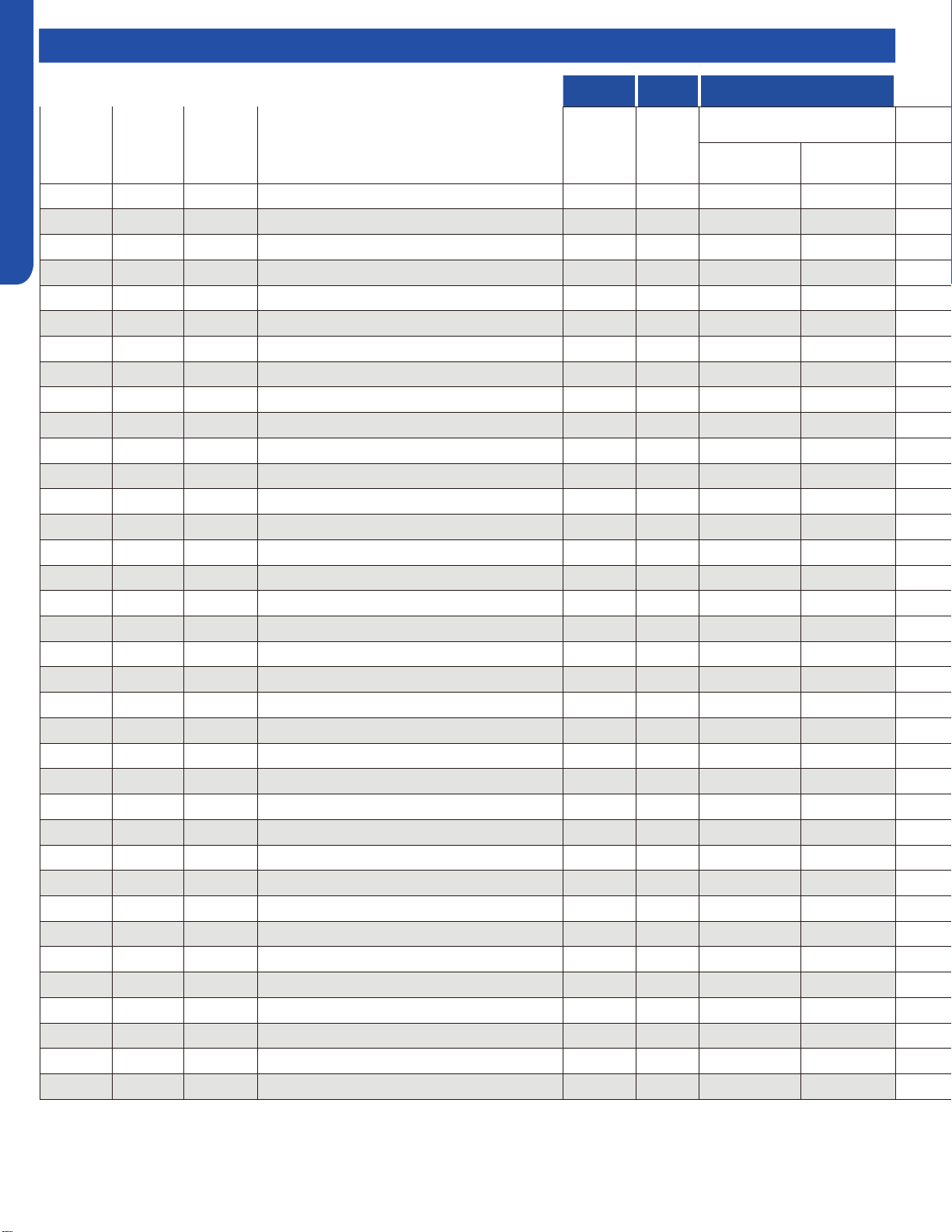
TROUBLESHOOTING & REFERENCES
ENGLISH
Topic Title
Master Error Code Chart
HIGHWALL CONSOLE COMPACT CASSETTE
Outdoor
Pro-Series
LED Display
(CAC)
Outdoor
Multi-Zone
LED Display
(CAC)
Outdoor
Single-Zone
LED1 Flash
(RAC)
FAULT DESCRIPTION
Digital
Display
Digital
Display
Panel LED Flash or
ID PCB LED Flash
Yellow Timer LED
(PCB LED5)
Green Run LED
(PCB LED1)
1
1 1 Outdoor EEPROM failure F12 F12 2 1
2
2 2 IPM overcurrent or short circuit F1 F1 2 2
/
/ 3 Outdoor alternating current, over current protection F22 F22 2 3
3
/ / Compressor over current during deceleration / / / /
4
4 4 Communication failure between the IPM and outdoor PCB F3 F3 2 4
5
5 5 Module operated overload (compressor overload protection) F20* F20* 2 5
6
6 6 Module low or high voltage F19* F19* 2 6
7
/ 7 Compressor current sampling circuit fault F27 F27 2 7
8
8 8 Overheat protection for discharge temperature F4 F4 2 8
9
9 9 Malfunction of the DC fan motor F8* F8* 2 9
10
10 10 Malfunction of defrost temperature sensor F21 F21 3 0
11
11 11 Suction temperature sensor failure F7 F7 3 1
12
12 12 Ambient temperature sensor failure F6 F6 3 2
13
13 13 Discharge temperature sensor failure F25 F25 3 3
/
/ 14 High outdoor suction temperature F30* F30* 3 4
14
/ / PFC circuit loop voltage / / / /
15
15 15 Communication failure between the indoor & outdoor unit E7 E7 3 5
16
16 16 Lack of refrigerant or discharging F13* F13* 3 6
17
17 17 4-way valve switching failure F14* F14* 3 7
18
18 18 Loss of synchronism detection F11 F11 3 8
/
/ 19 Position detection circuit fault of compressor F28 F28 3 9
19
/ / Low DC or AC voltage / / / /
/
/ 20 Terminal block temp too high F15* F15* 4 0
20
20 / Indoor thermal overload E9 / 4 0
/
21 21 Indoor unit overload protection, heating mode only. E9* / 4 1
/
21 / Indoor coil frosted E5 / 4 1
/
/ 22 Indoor anti-frosting protection E5* / 4 2
22
/ / PFC circuit loop overcurrent / / / /
/
/ 23 Indoor coil temperature (abnormal reading) / / / /
23
23 / Module thermal overload F5* F5* 4 3
24
24 24 Compressor start failure, over-current F2* F2* 4 4
25
25 25 Phase current protection (IPM) F23* F23 4 5
/
26 / MCU reset F9 F9 4 6
26
/ / IPM power supply phase loss (3-phase) / /
27
27 27 Module current detect circuit malfunction F24 F24 4 7
28
/ / Wiring error: Compressor to IPM / / / /
* Hidden indoor error code. LED1 will flash outdoors, but no error will appear on indoor unit display.
To view error code on indoor display, press and hold the Emergency button for 15 seconds.
PAGE 71
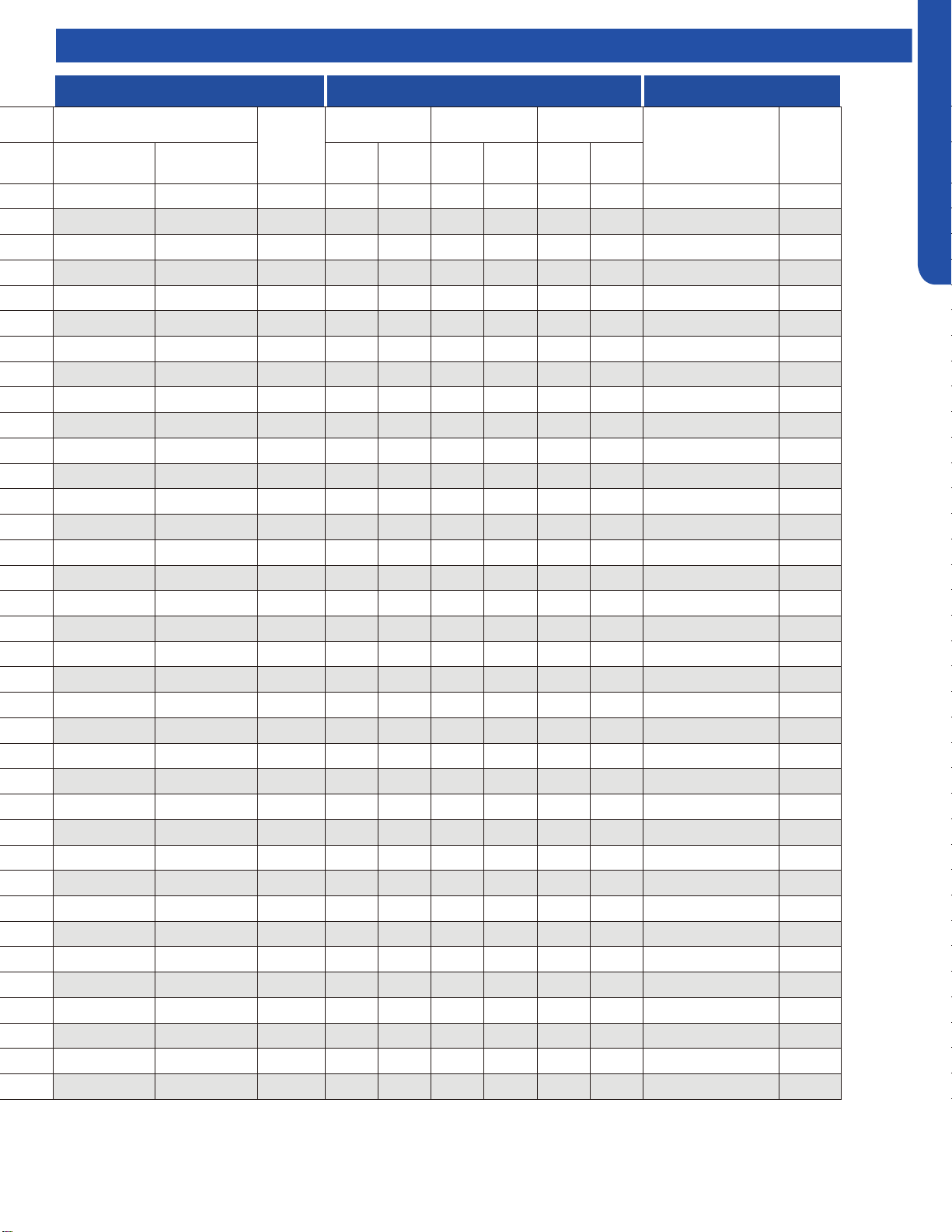
TROUBLESHOOTING & REFERENCES
ENGLISH
LARGE CASSETTE DUCTED WIRED CONTROLLER
Panel LED Flash or
ID PCB LED Flash
Panel
Display
(PB*****)
HIGH STATIC
MID-STATIC DUCT
(MSP)
SLIM DUCT
YRE-17A
QACT17A
YRE-16B
Yellow Timer LED
(PCB LED4)
Green Run LED
(PCB LED1)
LED4
(Yellow)
LED3
(Green)
LED4 LED3
LED4
(Yellow)
LED3
(Green)
2 1 15 2 1 2 1 2 1 15 21
2 2 16 2 2 2 2 2 2 16 22
/ / / / / / / / / 17 23
2 3 17 2 3 2 3 2 3 17 23
2 4 18 2 4 2 4 2 4 18 24
2 5 19 2 5 2 5 2 5 19 25
2 6 1A 2 6 2 6 2 6 1A 26
2 7 1B 2 7 2 7 2 7 1B 27
2 8 1C 2 8 2 8 2 8 1C 28
2 9 1D 2 9 2 9 2 9 1D 29
3 0 1E 3 0 3 0 3 0 1E 30
3 1 1F 3 1 3 1 3 1 1F 31
3 2 20 3 2 3 2 3 2 20 32
3 3 21 3 3 3 3 3 3 21 33
/ / / / / / / / / 22 34
3 4 22 3 4 3 4 3 4 22 34
3 5 23 3 5 3 5 3 5 23 35
3 6 24 3 6 3 6 3 6 24 36
3 7 25 3 7 3 7 3 7 25 37
3 8 26 3 8 3 8 3 8 26 38
/ / / / / / / / / 27 39
3 9 27 3 9 3 9 3 9 27 39
/ / / / / / / / / 28 40
4 0 28 4 0 4 0 4 0 28 40
/ / / / / / / / / 29 41
4 1 29 4 1 4 1 4 1 29 41
/ / / / / / / / / 2A 42
4 2 2A 4 2 4 2 4 2 2A 42
/ / / / / / / / / / /
4 3 2B 4 3 4 3 4 3 2B 43
4 4 2C 4 4 4 4 4 4 2C 44
4 5 2D 4 5 4 5 4 5 2D 45
4 6 2E 4 6 4 6 4 6 2E 46
/ / / 2F 47
4 7 2F 4 7 4 7 4 7 2F 47
/ / / / / / / / / / /
Master Error Code Chart
PAGE 72
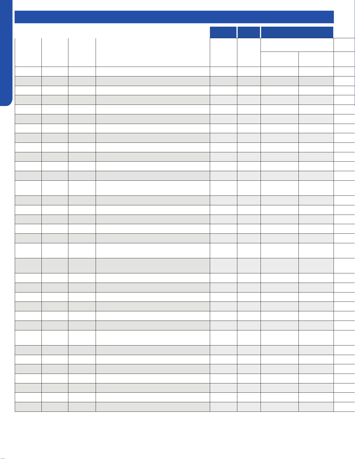
TROUBLESHOOTING & REFERENCES
ENGLISH
Master Error Code Chart
HIGHWALL CONSOLE COMPACT CASSETTE
Outdoor
Pro-Series
LED Display
(CAC)
Outdoor
Multi-Zone
LED Display
(CAC)
Outdoor
Single-Zone
LED1 Flash
(RAC)
FAULT DESCRIPTION
Digital
Display
Digital
Display
Panel LED Flash or
ID PCB LED Flash
Yellow Timer LED
(PCB LED5)
Green Run LED
(PCB LED1)
/
/ 28 Low refrigerant flow. Lockout. / / / /
/
28 / Liquid pipe sensor failure: Circuit A F10 F10 4 8
/
29 / Liquid pipe sensor failure: Circuit B F16 F16 4 9
/
30 / Liquid pipe sensor failure: Circuit C F17 F17 5 0
/
31 / Liquid pipe sensor failure: Circuit D F18 F18 5 1
/
32 / Gas pipe sensor failure: Circuit A F29 F29 5 2
/
33 / Gas pipe sensor failure: Circuit B F30 F30 5 3
/
34 / Gas pipe sensor failure: Circuit C F31 F31 5 4
/
35 / Gas pipe sensor failure: Circuit D F32 F32 5 5
/
36 / Gas pipe sensor failure: Circuit E F26 F26 5 6
/
/ 37 Outdoor pipe temperature protection in cooling mode F34 F34 5 7
37
/ / Compressor overcurrent detected by IPM / / / /
38
38 /
Malfunction of module temperature sensor momentary
power failure detection
F35 F35 5 8
39
39 39 Malfunction of condensing temperature sensor F36 F36 5 9
/
40 / Liquid pipe sensor failure - Circuit E F33 F33 6 0
/
41 / Toci temperature sensor failure F38 F38 6 1
42
42 / High Pressure switch open F39 F39 6 2
43
43 / Low Pressure switch open F40 F40 6 3
44
44 /
System high pressure protection: Overcharged, high
condensing temperature or malfunction of fan motor.
F41 F41 6 4
45
45 /
System low pressure protection: Undercharged, low
defrosting temperature, or malfunction of fan motor.
F42 F42 6 5
/
/ 46 Incorrect match between indoor & outdoor F43 F43 6 6
/
L0 / OAT less than -22°F (-30°C) / / / /
/
/ / Indoor ambient temperature sensor failure E1 E1 0 1
/
/ / Indoor coil temperature sensor failure E2 E2 0 2
/
/ / Indoor PCB EEPROM failure E4 E4 0 4
/
/ / Communication fault between the indoor and outdoor unit / / 0 7
/
/ /
Communication fault between the controller and Indoor
unit
/ E8 0 8
/
/ / DC voltage of the fan motor driver too high or too low / / / /
/
/ / Fan motor driver over 95°F (35°C) / / / /
/
/ / Indoor fan motor out of step / / / /
/
/ / Drain system malfunction / E12 0 12
/
/ / Zero cross signal detected wrong / E13 / C1 0 13
/
/ / Indoor fan motor malfunction E14* E14 0 14
/
/ / Indoor fan motor overcurrent / / / /
* Hidden indoor error code. LED1 will flash outdoors, but no error will appear on indoor unit display.
To view error code on indoor display, press and hold the Emergency button for 15 seconds.
PAGE 73
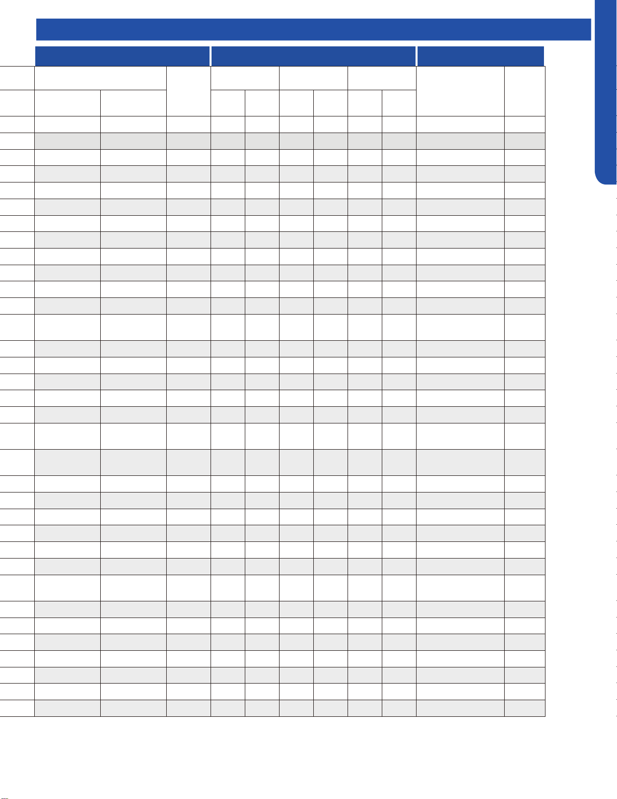
TROUBLESHOOTING & REFERENCES
ENGLISH
LARGE CASSETTE DUCTED WIRED CONTROLLER
Panel LED Flash or
ID PCB LED Flash
Panel
Display
(PB*****)
HIGH STATIC
MID-STATIC DUCT
(MSP)
SLIM DUCT
YRE-17A
QACT17A
YRE-16B
Yellow Timer LED
(PCB LED4)
Green Run LED
(PCB LED1)
LED4
(Yellow)
LED3
(Green)
LED4 LED3
LED4
(Yellow)
LED3
(Green)
/ / / / / / / / / / /
4 8 30 4 8 4 8 4 8 30 48
4 9 31 4 9 4 9 4 9 31 49
5 0 32 5 0 5 0 5 0 32 50
5 1 33 5 1 5 1 5 1 33 51
5 2 34 5 2 5 2 5 2 34 52
5 3 35 5 3 5 3 5 3 35 53
5 4 36 5 4 5 4 5 4 36 54
5 5 37 5 5 5 5 5 5 37 55
5 6 38 5 6 5 6 5 6 38 56
/ / / / / / / / / 39 57
5 7 39 5 7 5 7 5 7 39 57
5 8 3A 5 8 5 8 5 8 3A 58
5 9 3B 5 9 5 9 5 9 3B 59
6 0 3C 6 0 6 0 6 0 3C 60
6 1 3D 6 1 6 1 6 1 3D 61
6 2 3E 6 2 6 2 6 2 3E 62
6 3 3F 6 3 6 3 6 3 3F 63
6 4 40 6 4 6 4 6 4 40 64
6 5 41 6 5 6 5 6 5 41 65
/ / / / / / / / / 42 66
/ / / / / / / / / / /
0 1 01 0 1 0 1 0 1 01 01
0 2 02 0 2 0 2 0 2 02 02
0 4 04 0 4 0 4 0 4 04 04
0 7 07 0 7 0 7 0 7 07 07
0 8 08 0 8 0 8 0 8
Flashing 07 (YR-E17) /
Flashing ! (QACT17A)
/
/ / / 0 17 / / 0 17 11 17
/ / / 0 18 / / 0 18 12 18
/ / / 0 19 / / 0 19 13 19
0 12 0C 0 12 0 12 0 12 0C 12
0 13 0D 0 13 0 13 0 13 0D 13
0 14 0E 0 14 0 14 0 14 0E 14
/ / / 0 15 / / 0 15 0F 15
Master Error Code Chart
PAGE 74

Check This First Outdoor Unit ..........................................................................................................................76
Check This First Indoor Unit .............................................................................................................................77
Wiring Diagram Reference...................................................................................................... ..........................78
F1/LED1: 2 Flash
.............................................................................................................................................79
F2/LED1: 24 Flash ...........................................................................................................................................81
F3/LED1: 4 Flash .............................................................................................................................................83
F4/LED1: 8 Flash .............................................................................................................................................85
F6/LED1: 12 Flash
F7/LED1: 11 Flash
F21/LED1: 10 Flash
F25/LED1: 13 Flash
E1/LED1: No Flash
E2/LED1: No Flash ...........................................................................................................................................87
F6/LED1: 12 Flash, F7/LED1: 11 Flash, F21/LED1: 10 Flash, F25/LED1: 13 Flash,
E1/
LED1: No Flash, E2/LED1: No Flash.............................................................................................................88
F
8/LED1: 9 Flash .............................................................................................................................................89
F11/LED1: 18 Flash .........................................................................................................................................91
F12/LED1: 1 Flash ...........................................................................................................................................93
E5/LED1: 22 Flash............................................................................................................................................94
E7/LED1: 15 Flash ...........................................................................................................................................96
Error Code (Indoor)
E14 ..................................................................................................................................................................99
Checking System Components.........................................................................................................................101
ERROR CODES and Troubleshooting
Error Code (Indoor/outdoor)
PAGE 75
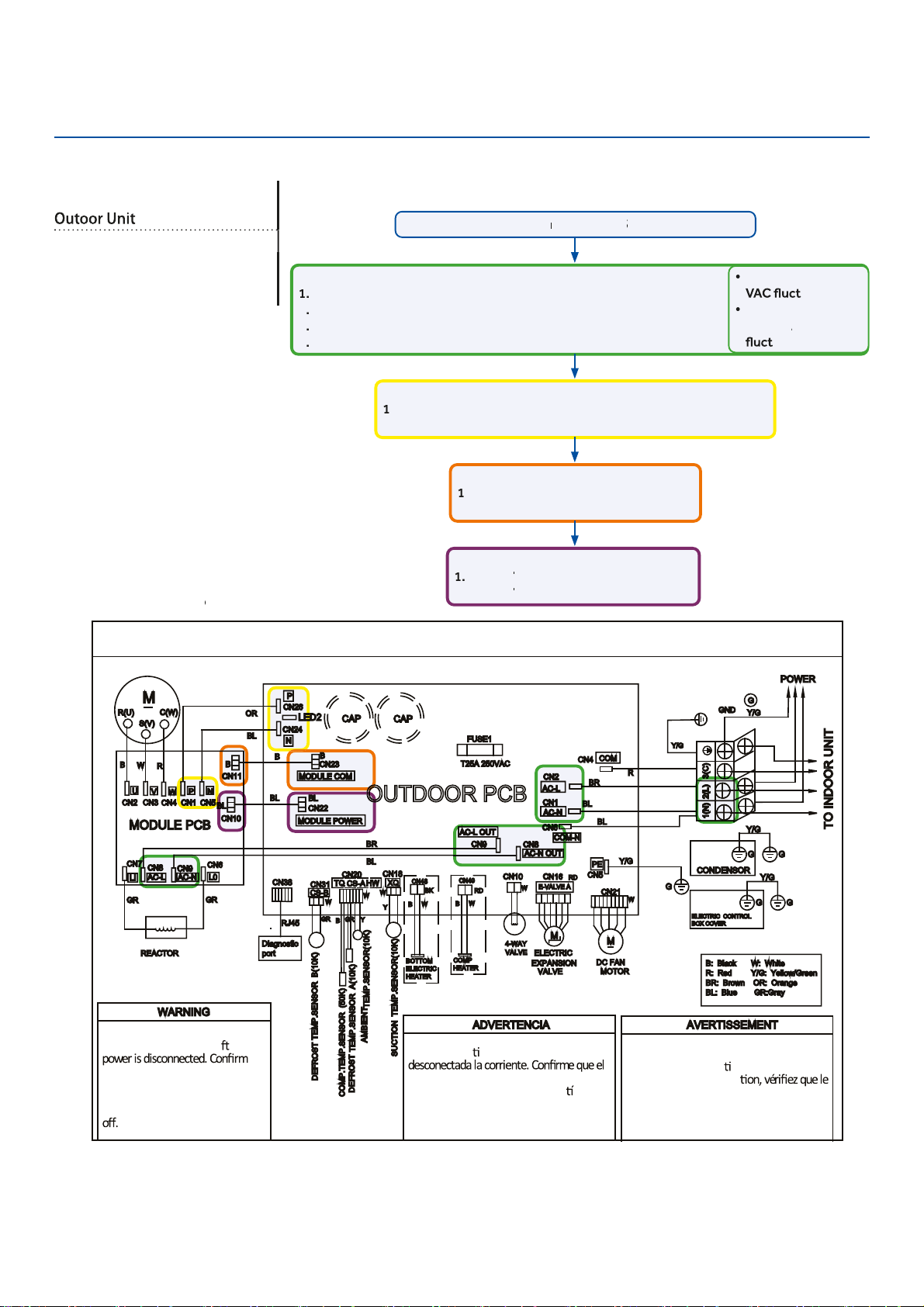
Troubleshooting
Ou
●
tdoor Board Diagram
OUTDOOR UNIT WIRING DIAGRAM
COMPRESSOR
Electrical Shock Haza
●
rd
Capacitor retains charge a
e
●
r
voltage at capacitor has diss
●
ipated
(<10V DC) with hand held voltmeter
before servicing. LED2 light
between CN24 and CN26 should be
Riesgo de Descarga Eléctrica
El capacitor re
ene carga una vez
voltaje del capacitor se haya disipado (<10V
DC) apoyando la mano sobre el vol
metro
antes de realizar el servicio técnico. La luz
LED2 que se encuentra entre CN24 y CN26
deberá estar apagada.
Risque de choc électrique
Le condensateur conserve sa charge après la
coupure de l’alimenta
on électrique. Avant
de procéder à une répara
courant au condensateur s’est dissipé
(<10 VCC) à l’aide d’un voltmètre manuel. Le
voyant LED2 entre CN24 et CN26 doit être
éteint.
0011509127
Check This First
Models:
1U09EH2VHE
1U12EH2VHE
1U18EH2VHE
Line
v
oltage
a
v
ailable at:
1
.
TERMINAL
S
TRIP - 1(N) & 2 (L)
2
.
A
C
-L &
A
C
-N at the PCB - CN2 & CN1
3
.
A
C
-L OUT &
A
C
-N OUT at the PCB - CN8 & CN9
4
.
A
C
-L &
A
C
-N at the I
P
M -CN8 & CN9 (9K) / CN1 & CN2 (12K/18K)
310+ VDC
a
v
ailable at:
1
.
P & N at the I
P
M - CN1 & CN5 (9K) / CN8 & CN9 (12K/18K)
2
.
P & N at the PCB - CN24 & CN26
Module
C
OM 5-G-15 VDC
a
v
ailable at:
1
.
CN23 at the PCB
2
.
CN11 at the I
P
M
Module p
o
w
er 5-G-15 VDC
a
v
ailable at:
1
.
CN22
A
T THE PCB
A
A
2
.
CN10
A
T THE I
A
A
P
M
1 (N) and 3 (C): 0-80
uating
2 (L) and 3 (C):
0-140
V
A
V
V
C
uating
Wiring Diag
r
am
R
e
f
e
f
f
r
en
c
e
Conditions Needed for Basic Operation
3-minu
t
es of
time
del
a
y
f
r
f
f
om
the
call
f
or heating
f
f
or
c
ooling
ERROR CODES and Troubleshooting
PAGE 76
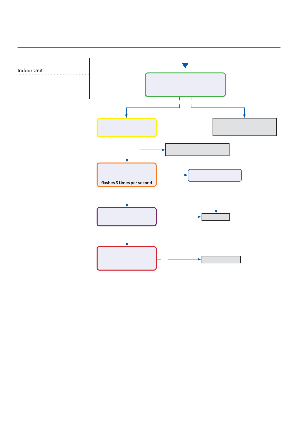
Troubleshooting
Start
See reverse side for
wiring diagram and
relevant color-coded
test positions.
Yes
●
Yes
●
Yes
●
Yes
●
No
No
No
Yes No
No
Determine source of lost
power from OD unit or phase
imbalance from building power
Determine source of lost
communication from OD unit
Replace PCB
Replace sensor
There is 230 VAC (+/- 10%) at terminal
strip connections 1(N) and 2(L), and
no more than a 2% deviation between
each leg and ground?
There is a pulsing 0 to 80
VAC between terminal strip
connections 1(N) and 3(C)?
There is 230 VAC at
terminals CN17 and CN21
on the PCB, and the LED
There is 5 VDC at CN6
across both sets of black
sensor wires?
The sensor resistance is
within 3% of the value listed
in the Service Manual sensor
resistance table?
Wiring and connections
are in good condition?
Check This First
Models:
AW09EH2VHD/ASYW09URDWD
AW12EH2VHD/ASYW12URDWD
AW18EH2VHD/ASYW18URDWD
ERROR CODES and Troubleshooting
PAGE 77
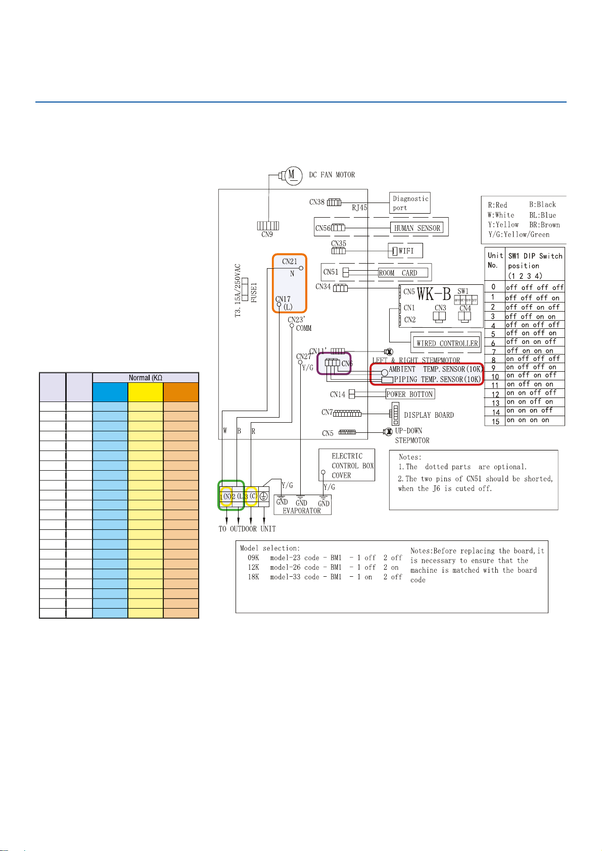
Troubleshooting
Check This First - Indoor Unit
Wiring Diagram Reference
Sensor Resistance Table
ERROR CODES and Troubleshooting
PAGE 78
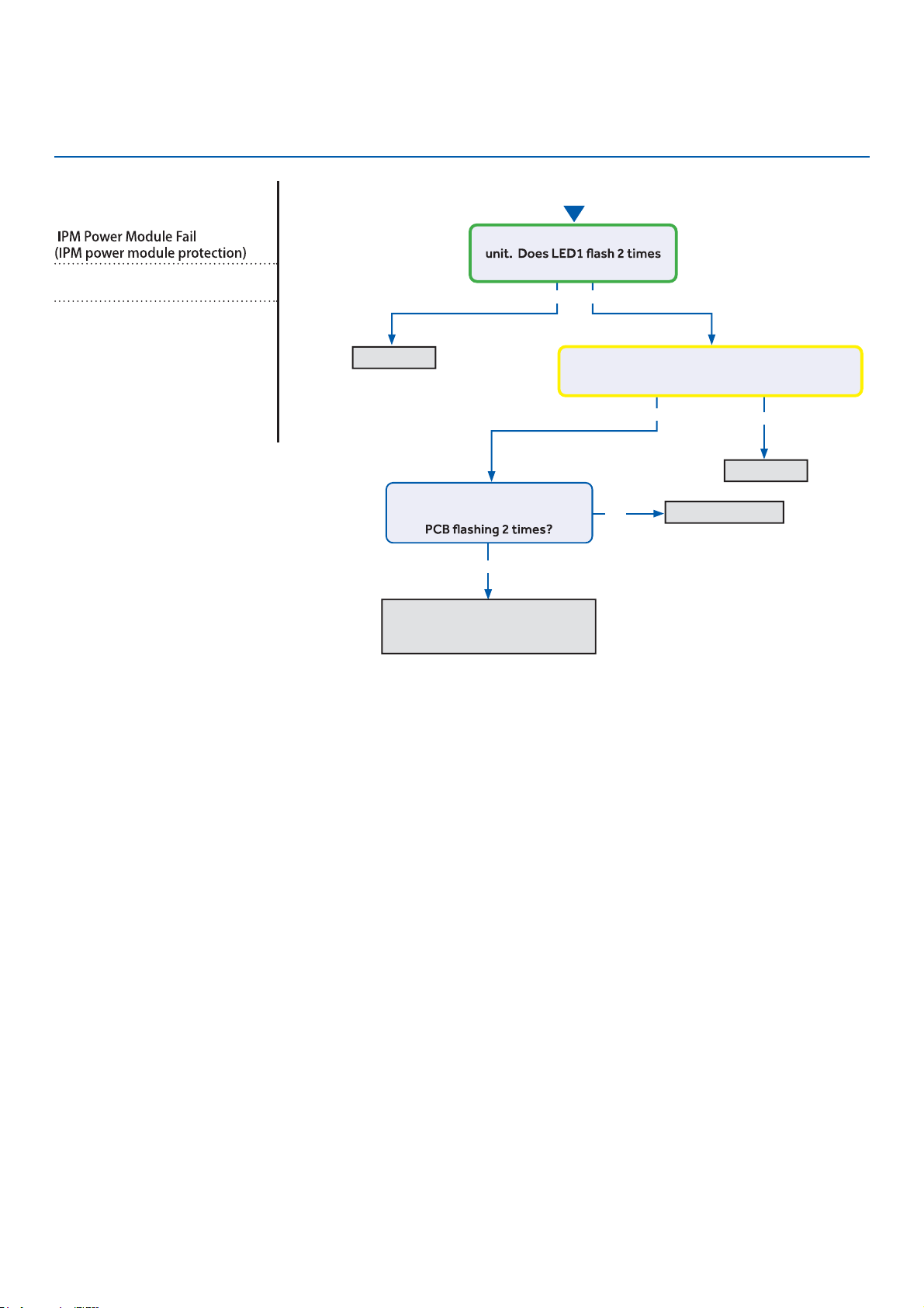
Troubleshooting
See reverse side for
wiring diagram and
relevant color-coded
test positions.
Error Code (Indoor/Outdoor)
F1/LED1: 2 Flash
Complete the “Check This First” Flow
Chart before continuing.
Models:
AW09EH2VHD/ASYW09URDWD
●
AW12EH2VHD/ASYW12URDWD
AW18EH2VHD/ASYW18URDWD
1U09EH2VHE/ASH109URDSE
1U12EH2VHE/ASH112URDSE
1U18EH2VHE/ASH118URDSE
Yes
●
No
No
Yes
Yes No
Start
Cycle power to the outdoor
before the compressor starts?
Compressor runs for 10 min.
and stops with LED in center of
DC voltage from P-U, P-V, P-W is 150-160VDC,
DC voltage from N-U, N-V, N-W 150-160VDC?
Replace IPM
Replace IPM
Normal operation
Check coil cleanliness,
EEV operation, compressor
windings, and refrigerant charge
ERROR CODES and Troubleshooting
PAGE 79
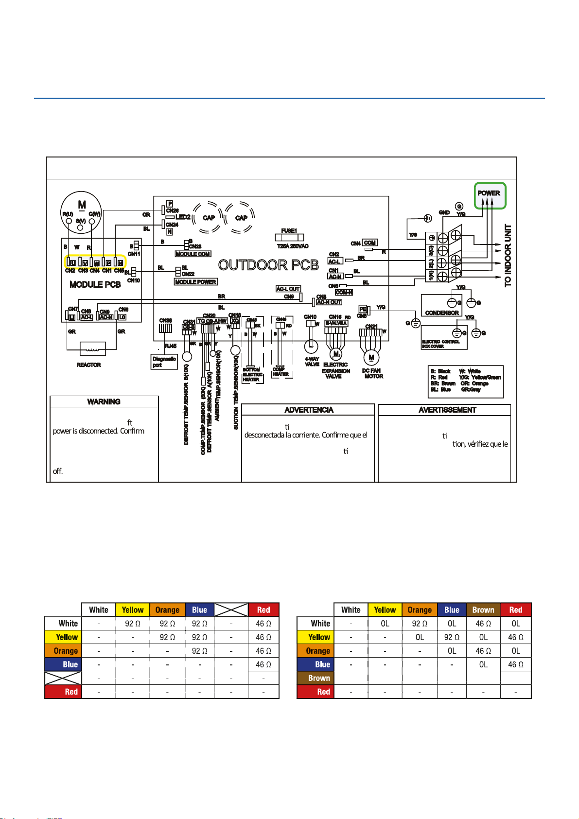
Troubleshooting
Error Code: F1/LED1: 2 Flash
Wiring Diagram Reference
OUTD
●
OOR UNIT WIRING DIAGRAM
COMPRESSOR
Electrical Shock Hazard
Capacitor retains charge a
er
voltage at capacitor has dissipated
●
(<10V DC) with hand held voltmeter
before servicing. LED2 light
between CN24 and CN26 should be
●
Riesgo de Descarga Eléctrica
El capacitor re
ene carga una vez
voltaje del capacitor se haya disipado (<10V
DC) apoyando la mano sobre el vol
metro
antes de realizar el servicio técnico. La luz
LED2 que se encuentra entre CN24 y CN26
deberá estar apagada.
Risque de choc électrique
Le condensateur conserve sa charge après la
coupure de l’alimenta
on électrique. Avant
de procéder à une répara
courant au condensateur s’est dissipé
(<10 VCC) à l’aide d’un voltmètre manuel. Le
voyant LED2 entre CN24 et CN26 doit être
éteint.
0011509127
EEV Resistance Values
EEV (6-pin, 6 wire)
EEV (6-pin, 5 wire)
ERROR CODES and Troubleshooting
PAGE 80
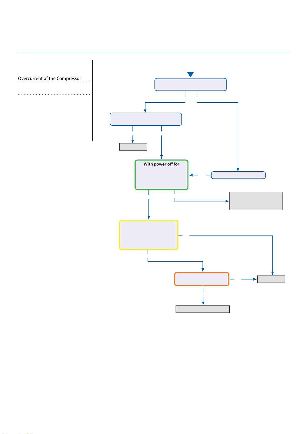
Troubleshooting
See reverse side for
wiring diagram and
relevant color-coded
test positions.
Yes
●
Yes No
Yes
●
No
No
Yes
Yes
No
No
Yes
Continue to monitor;
the system is starting
under an abnormal load
Replace IPM
Replace IPM
Check refrigerant charge
Start
The set temperature is 5°F max.
from the room temperature?
Does the error code display
before the compressor starts?
5 min and back on,
compressor exceeds
over-current point in
Service Manual?
There is pulsing 50-200
VAC at compressor
terminals U, V, and W , read
from the terminal solder
points on the IPM?
There is 264-373 VDC at
P and N on the IPM?
Change set temperature
Error Code (Indoor/Outdoor)
F2/LED1: 24 Flash
Complete the “Check This First” Flow
Chart before continuing.
Models:
AW09EH2VHD/ASYW09URDWD
AW12EH2VHD/ASYW12URDWD
AW18EH2VHD/ASYW18URDWD
1U09EH2VHE/ASH109URDSE
1U12EH2VHE/ASH112URDSE
1U18EH2VHE/ASH118URDSE
ERROR CODES and Troubleshooting
PAGE 81
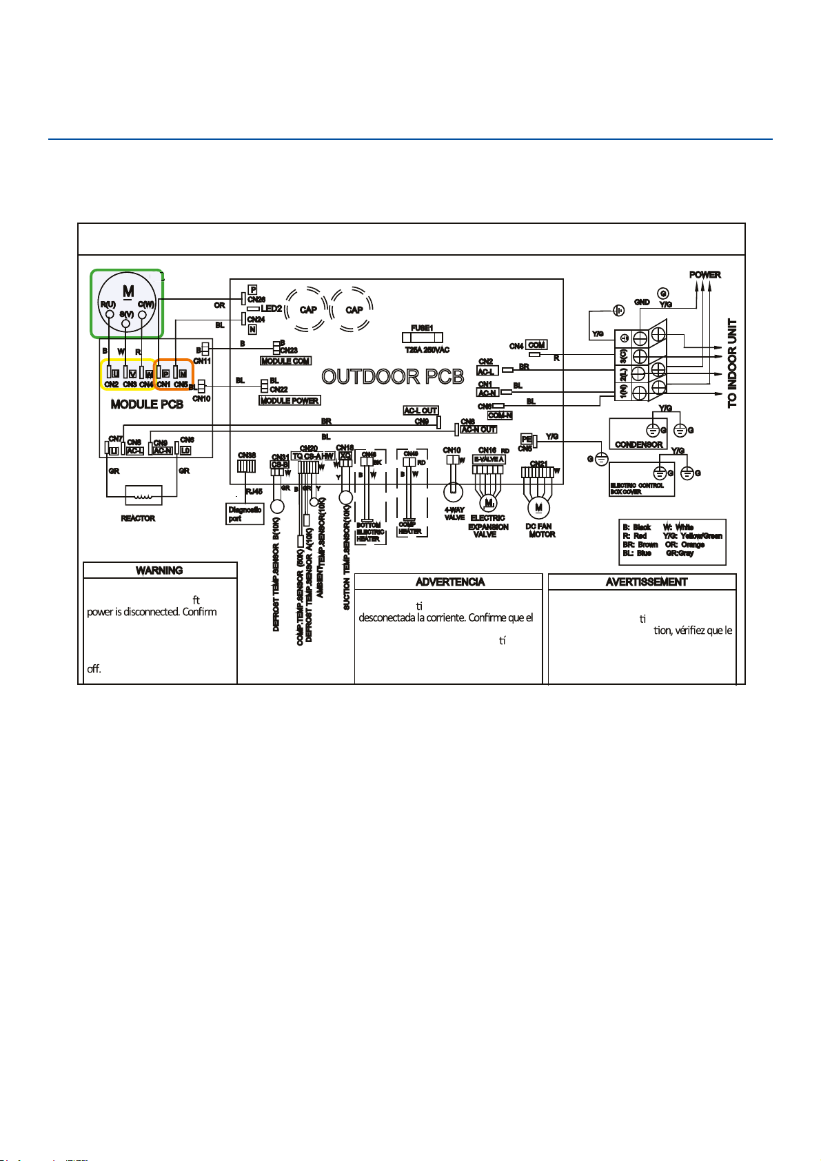
Troubleshooting
●
OUTDOOR UNIT WIRING DIAGRAM
COMPRESSOR
Electrical Shock Hazard
●
Capacitor retains charge a er
voltage at capacitor has dissi
●
pated
(<10V DC) with hand held voltmeter
before servicing. LED2 light
between CN24 and CN26 should be
Riesgo de Descarga Eléctrica
El capacitor re
ene carga una vez
voltaje del capacitor se haya disipado (<10V
DC) apoyando la mano sobre el vol
metro
antes de realizar el servicio técnico. La luz
LED2 que se encuentra entre CN24 y CN26
deberá estar apagada.
Risque de choc électrique
Le condensateur conserve sa charge après la
coupure de l’alimenta
on électrique. Avant
de procéder à une répara
courant au condensateur s’est dissipé
(<10 VCC) à l’aide d’un voltmètre manuel. Le
voyant LED2 entre CN24 et CN26 doit être
éteint.
0011509127
Error Code: F2/LED1: 24 Flash
Wiring Diagram Reference
COMPR
COMPR
ERROR CODES and Troubleshooting
PAGE 82

Troubleshooting
See reverse side for
●
wiring diagram and
relevant color-coded
test positions.
Yes
●
Yes
●
Yes
●
Start
No
No
No
No
No
Line voltage at AC-L & AC-N
on the PCB (CN2 & CN1)?
Line voltage at AC-L & AC-N
on the IPM (9K CN8 & CN9 /
12K/18K CN1 & CN2)?
Module Power voltage -
CN22 on the PCB:
Across pins 1 & 2 = 5VDC
Across pins 2 & 3 = 15VDC?
Module Power voltage -
CN10 on the IPM
Across pins 1 & 2 = 5VDC
Across pins 2 & 3 = 15VDC?
Module Com voltage - CN23 on the PCB
With a call for Heating or Cooling,
Across pins 1 & 2 = 5VDC
Across pins 2 & 3 = 15VDC ?
Module Com voltage - CN11 on the IPM
With a call for Heating or Cooling,
Across pins 1 & 2 = 5VDC
Across pins 2 & 3 = 15VDC?
Yes
Yes
Yes
No
Yes
No
Yes
No
Check incoming power
from building
Replace PCB
Replace PCB
Replace fuse
Replace AC-L & AC-N
wiring harness
Replace module
power wiring
harness
Replace Module
COM Wiring
Harness
Replace PCB
Replace IPM
Fuse 1 is OK?
Line voltage at
AC-L OUT & AC-N
OUT on the PCB
(CN8 & CN9)?
Error Code (Indoor/Outdoor)
F3/LED1: 4 Flash
Complete the “Check This First” Flow
Chart before continuing.
Models:
AW09EH2VHD/ASYW09URDWD
AW12EH2VHD/ASYW12URDWD
AW18EH2VHD/ASYW18URDWD
1U09EH2VHE/ASH109URDSE
1U12EH2VHE/ASH112URDSE
1U18EH2VHE/ASH118URDSE
ERROR CODES and Troubleshooting
PAGE 83
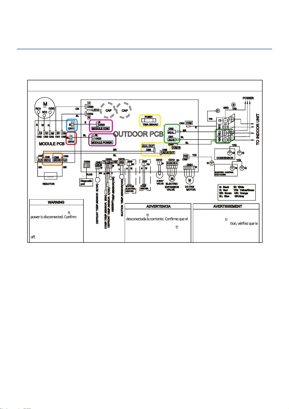
Troubleshooting
OUTD
●
OOR UNIT WIRING DIAGRAM
COMPRESSOR
Electrical Shock Hazard
●
Capacitor retains charge a er
voltage at capacitor has dissipated
(<10V DC) with hand held voltmeter
before servicing. LED2 light
between CN24 and CN26 should be
Riesgo de Descarga Eléctrica
El capacitor re
ene carga una vez
voltaje del capacitor se haya disipado (<10V
DC) apoyando la mano sobre el vol metro
antes de realizar el servicio técnico. La luz
LED2 que se encuentra entre CN24 y CN26
deberá estar apagada.
Risque de choc électrique
Le condensateur conserve sa charge après la
coupure de l’alimenta
on électrique. Avant
de procéder à une répara
courant au condensateur s’est dissipé
(<10 VCC) à l’aide d’un voltmètre manuel. Le
voyant LED2 entre CN24 et CN26 doit être
éteint.
0011509127
Error Code: F3/LED1: 4 Flash
Wiring Diagram Reference
ERROR CODES and Troubleshooting
PAGE 84
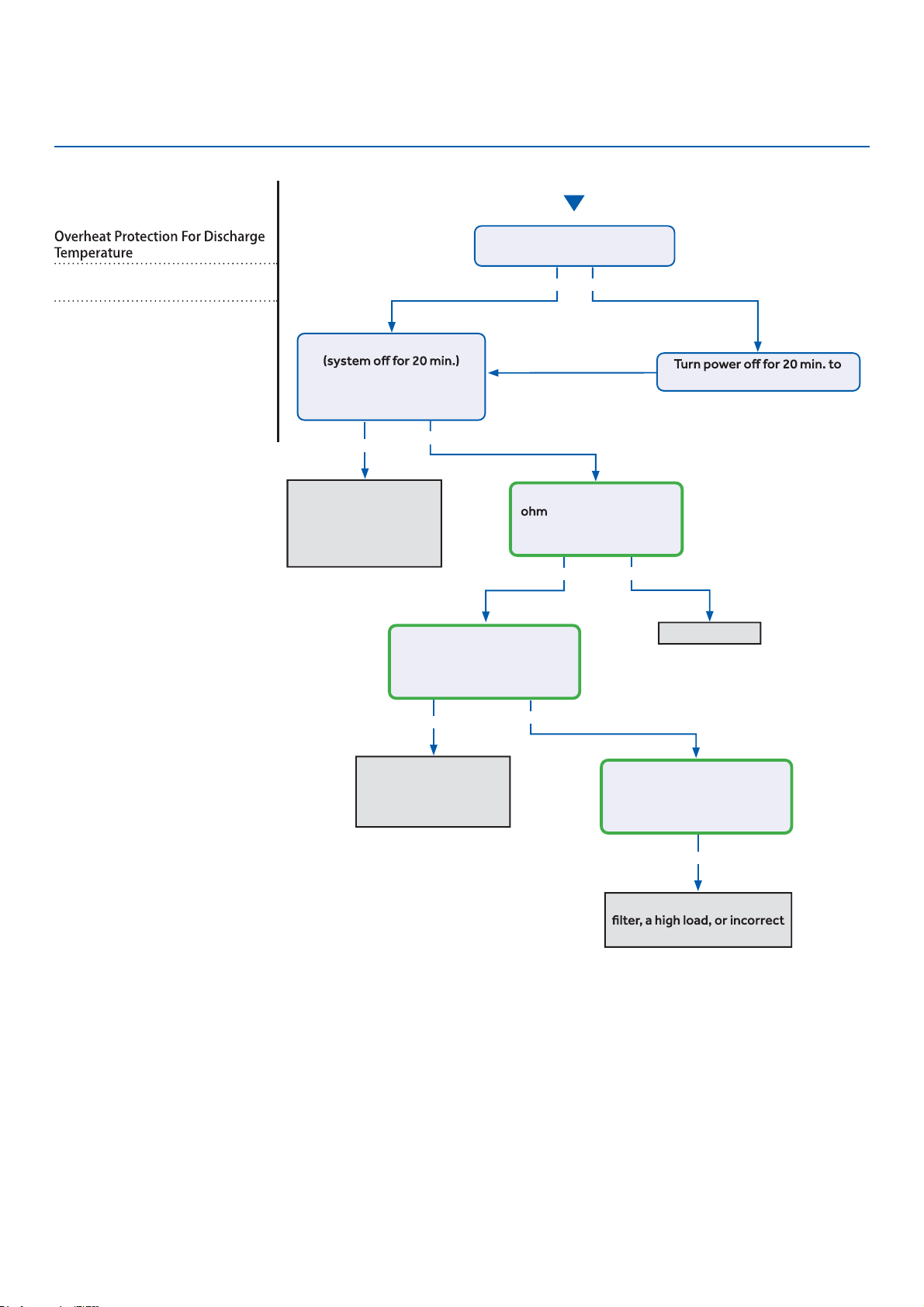
Troubleshooting
Start
See reverse side for
wiring diagram and
relevant color-coded
test positions.
●
Yes
●
Yes
●
Yes
Yes No
No
No
Yes
No
Recover refrigerant,
remove moisture and
air from system, charge
with fresh refrigerant
to nameplate amount
Check for a fan motor
issue, restricted line
set or EEV, or lack of
refrigerant
Check for a plugged coil or
refrigerant charge
●
Replace sensor
The discharge line temperature
is below 230°F/110°C?
The discharge sensor
reading matches the
resistance table in the
Service Manual?
With system on, the
discharge sensor climbs to
230°F within a short time, and
the compressor stops?
With system on, the
discharge sensor climbs to
230°F after several minutes,
and the compressor stops?
allow the discharge line to cool
Refrigerant static test
indicates head pressure
converted to temperature is
higher than ambient?
Error Code (Indoor/Outdoor)
F4/LED1: 8 Flash
Complete the “Check This First” Flow
Chart before continuing.
Models:
AW09EH2VHD/ASYW09URDWD
AW12EH2VHD/ASYW12URDWD
AW18EH2VHD/ASYW18URDWD
1U09EH2VHE/ASH109URDSE
1U12EH2VHE/ASH112URDSE
1U18EH2VHE/ASH118URDSE
ERROR CODES and Troubleshooting
PAGE 85
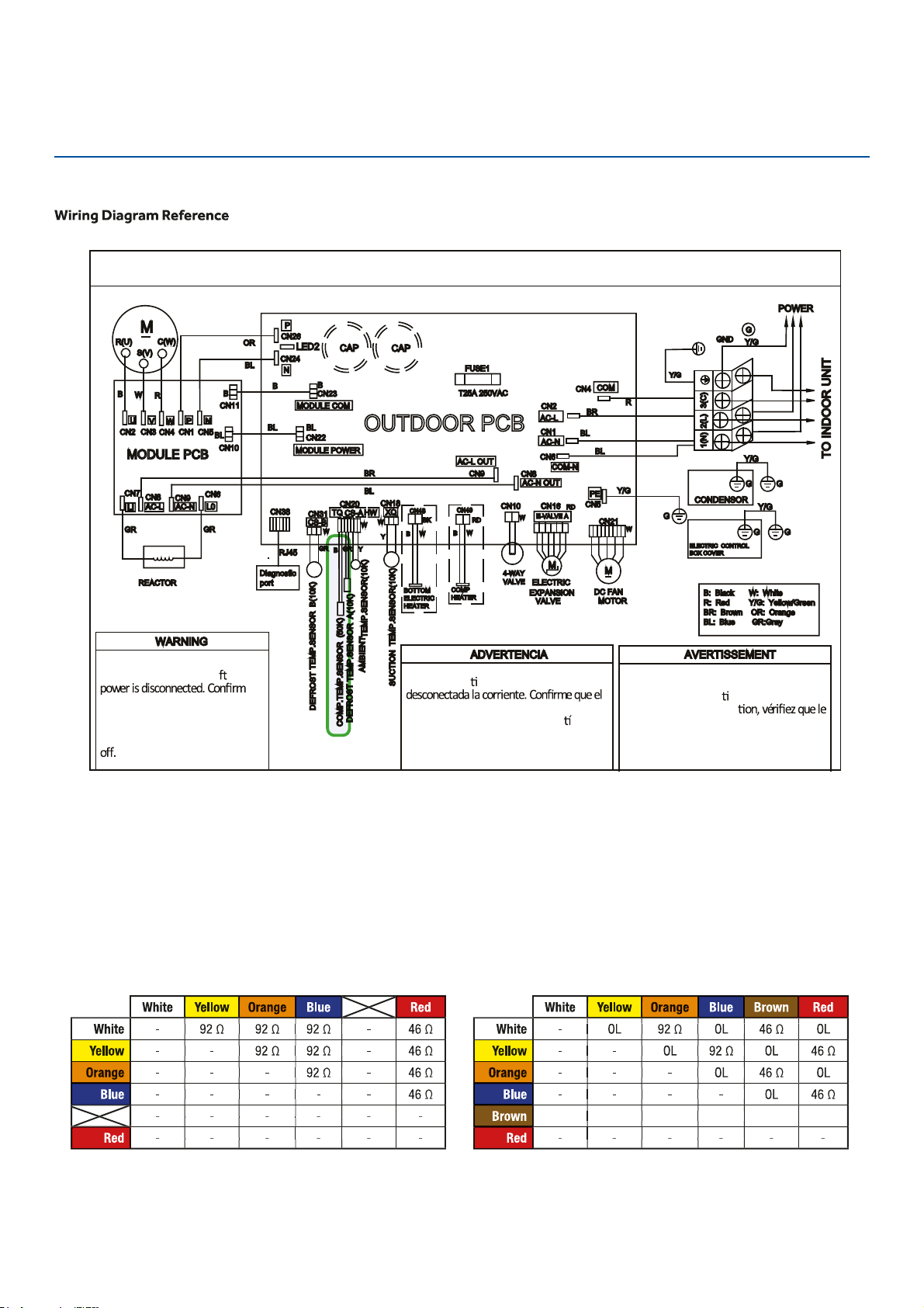
Troubleshooting
OUTDOOR UNIT WIRING DIAGRAM
●
COMPRESSOR
Electrical Shock Hazard
●
Capacitor retains charge a er
voltage at capacitor has dissipated
●
(<10V DC) with hand held voltmeter
before servicing. LED2 light
between CN24 and CN26 should be
Riesgo de Descarga Eléctrica
El capacitor re
ene carga una vez
voltaje del capacitor se haya disipado (<10V
DC) apoyando la mano sobre el vol
metro
antes de realizar el servicio técnico. La luz
LED2 que se encuentra entre CN24 y CN26
deberá estar apagada.
Risque de choc électrique
Le condensateur conserve sa charge après la
coupure de l’alimenta
on électrique. Avant
de procéder à une répara
courant au condensateur s’est dissipé
(<10 VCC) à l’aide d’un voltmètre manuel. Le
voyant LED2 entre CN24 et CN26 doit être
éteint.
0011509127
Error Code: F4/LED1: 8 Flash
EEV Resistance Values
EEV (6-pin, 6 wire)
EEV (6-pin, 5 wire)
ERROR CODES and Troubleshooting
PAGE 86
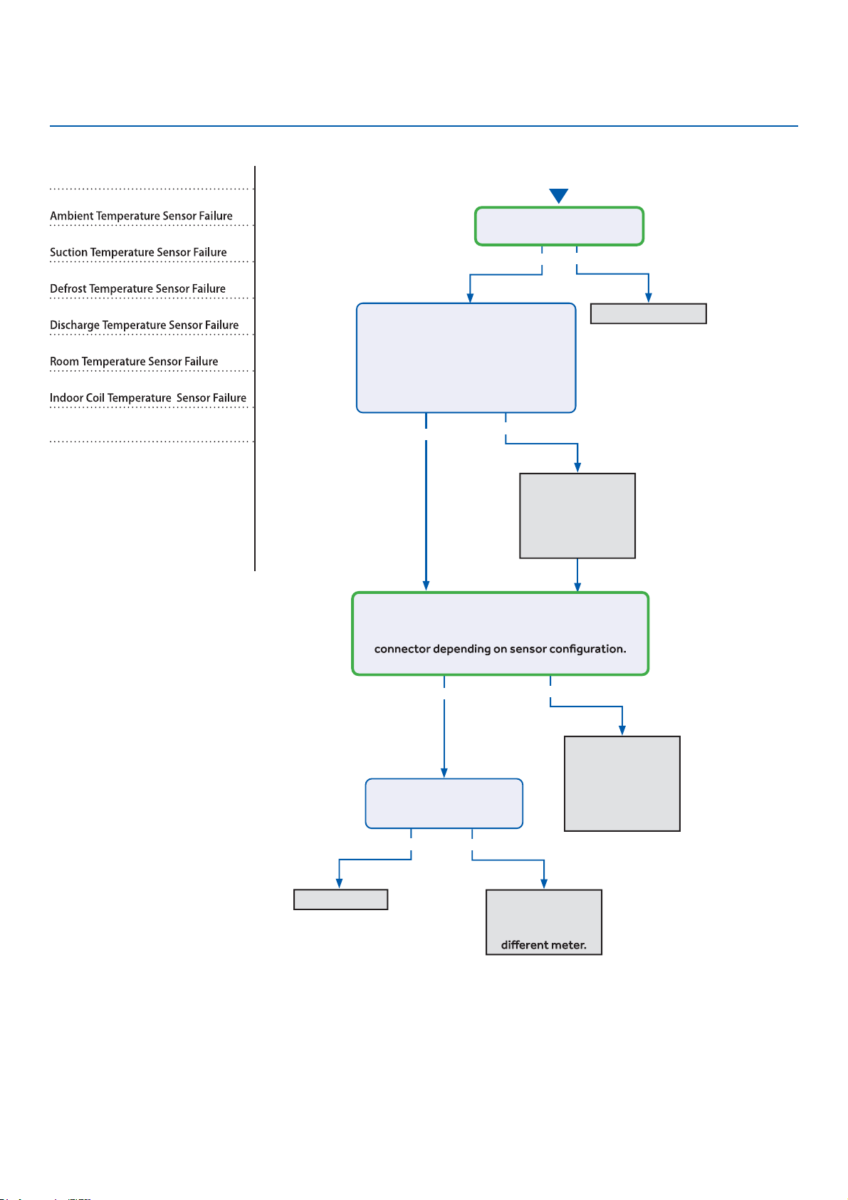
Troubleshooting
See reverse side for
wiring diagram, relevant
color-coded test
positions, and sensor
●
resistance values.
●
Error Codes (Indoor/Outdoor)
F6/LED1: 12 Flash
F7/LED1: 11 Flash
F21/LED1: 10 Flash
F25/LED1: 13 Flash
E1/LED1: No Flash
E2/LED1: No Flash
Complete the “Check This First” Flow
Chart before continuing.
Models:
AW09EH2VHD/ASYW09URDWD
AW12EH2VHD/ASYW12URDWD
AW18EH2VHD/ASYW18URDWD
1U09EH2VHE/ASH109URDSE
1U12EH2VHE/ASH112URDSE
1U18EH2VHE/ASH118URDSE
Yes
Yes
●
Yes
●
Yes
No
No
No
No
Re-seat connector
Replace sensor.
Go to next step
to test the board
as well before
replacing sensor.
Replace main
board. Replace
sensor as well if
resistance was
incorrect in the
previous step.
Re-seat and
re-check sensor
resistance with a
●
Replace sensor
Start
Is connector plugged in and
seated securely?
Disconnect power and un-plug senor
connector from the board.
Check resistance across the set of
wires for the faulting sensor. Does
the resistance correspond to the
temperature located in the respective
chart ? (See Reverse side.)
Reconnect sensor to the board and re-apply power.
Check voltage between the two corresponding
solder joints or through the top of the Molex
Is the voltage ~5VDC?
Is the temperature at the
sensor out of operating
range (+/- 3%)?
ERROR CODES and Troubleshooting
PAGE 87
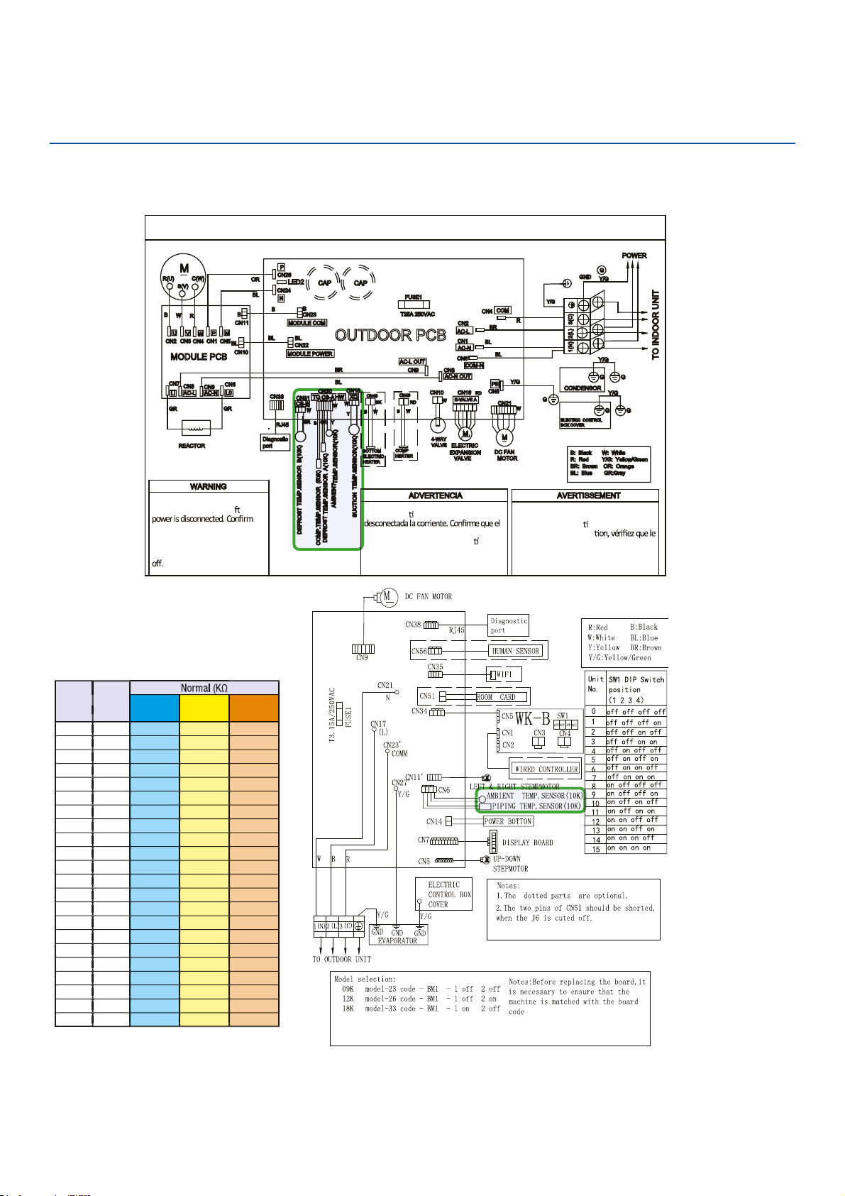
Troubleshooting
Outdoor Board Diagram
●
09K
12K-18K
OUTDOOR UNIT WIRING DIAGRAM
COMPRESSOR
Electrical Shock Hazard
Capacitor retains charge a er
voltage at capacitor has dissipated
(<10V DC) with hand held voltmeter
before servicing. LED2 light
between CN24 and CN26 should be
Riesgo de Descarga Eléctrica
El capacitor re ene carga una vez
voltaje del capacitor se haya disipado (<10V
DC) apoyando la mano sobre el vol
metro
antes de realizar el servicio técnico. La luz
LED2 que se encuentra entre CN24 y CN26
deberá estar apagada.
Risque de choc électrique
Le condensateur conserve sa charge après la
coupure de l’alimenta
on électrique. Avant
de procéder à une répara
courant au condensateur s’est dissipé
(<10 VCC) à l’aide d’un voltmètre manuel. Le
voyant LED2 entre CN24 et CN26 doit être
éteint.
0011509127
Sensor Resistance Table
Error Code: F6/LED1: 12 Flash, F7/LED1: 11 Flash, F21/LED1: 10 Flash, F25/LED1: 13 Flash,
E1/LED1: No Flash, E2/LED1: No Flash
Wiring Diagram Reference
ERROR CODES and Troubleshooting
PAGE 88
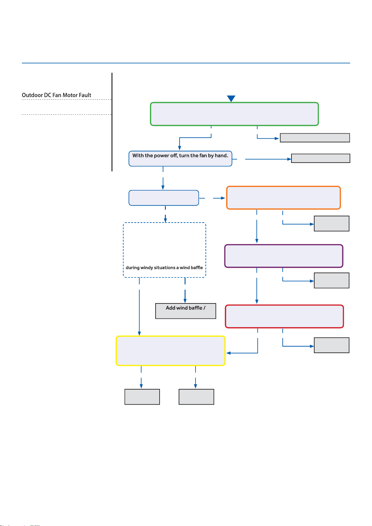
Troubleshooting
See reverse side for
●
wiring diagram and
relevant color-coded
test positions.
No
●
Error Code (Indoor/Outdoor)
F8/LED1: 9 Flash
Complete the “Check This First” Flow
Chart before continuing.
Models:
AW09EH2VHD/ASYW09URDWD
AW12EH2VHD/ASYW12URDWD
AW18EH2VHD/ASYW18URDWD
1U09EH2VHE/ASH109URDSE
1U12EH2VHE/ASH112URDSE
1U18EH2VHE/ASH118URDSE
Yes
●
Yes
●
Yes
Yes
No
●
Yes
No
Yes
No
protection from wind.
Fix incoming power supply
Replace the fan motor
Replace the
fan motor.
Replace the
main board.
Start
Check the incoming voltage.
Is it 208/230VAC (+/- 10%) between L1/L2?
104/115VAC (+/- 10%) from L1 to GROUND and L2 to GROUND?
Does it move / rotate smoothly?
Re-apply power. Does the
fan come on and spin?
Measure DC voltage at fan motor plug
CN21 between the Pin 6 (BLUE) and Pin 3
(BLACK) wire while spinning the fan motor.
Does it generate 2~9VDC?
No
No
No
Replace the
main board.
Replace the
main board.
Replace the
main board.
Measure DC voltage at fan motor plug CN21
between Pin 1 (RED) and Pin 3 (BLACK).
Does it measure 300~380VDC (+/-10%)?
Measure DC voltage at fan motor plug CN21
between Pin 4 (WHITE) and Pin 3 (BLACK).
Does it measure between 13.5-16.5VDC?
Measure DC voltage at fan motor plug CN21
between Pin 5 (YELLOW) and Pin 3 (BLACK).
Does it measure between 2-6VDC?
Before going to the next step, is the
unit in an area susceptible to high
winds? High winds blowing into the
fan may cause added resistance
and subsequently lower fan speeds
enough to cause the unit to fault. If
this is the case the unit only faults
may need to be added.
Not Windy Windy
Yes
ERROR CODES and Troubleshooting
PAGE 89
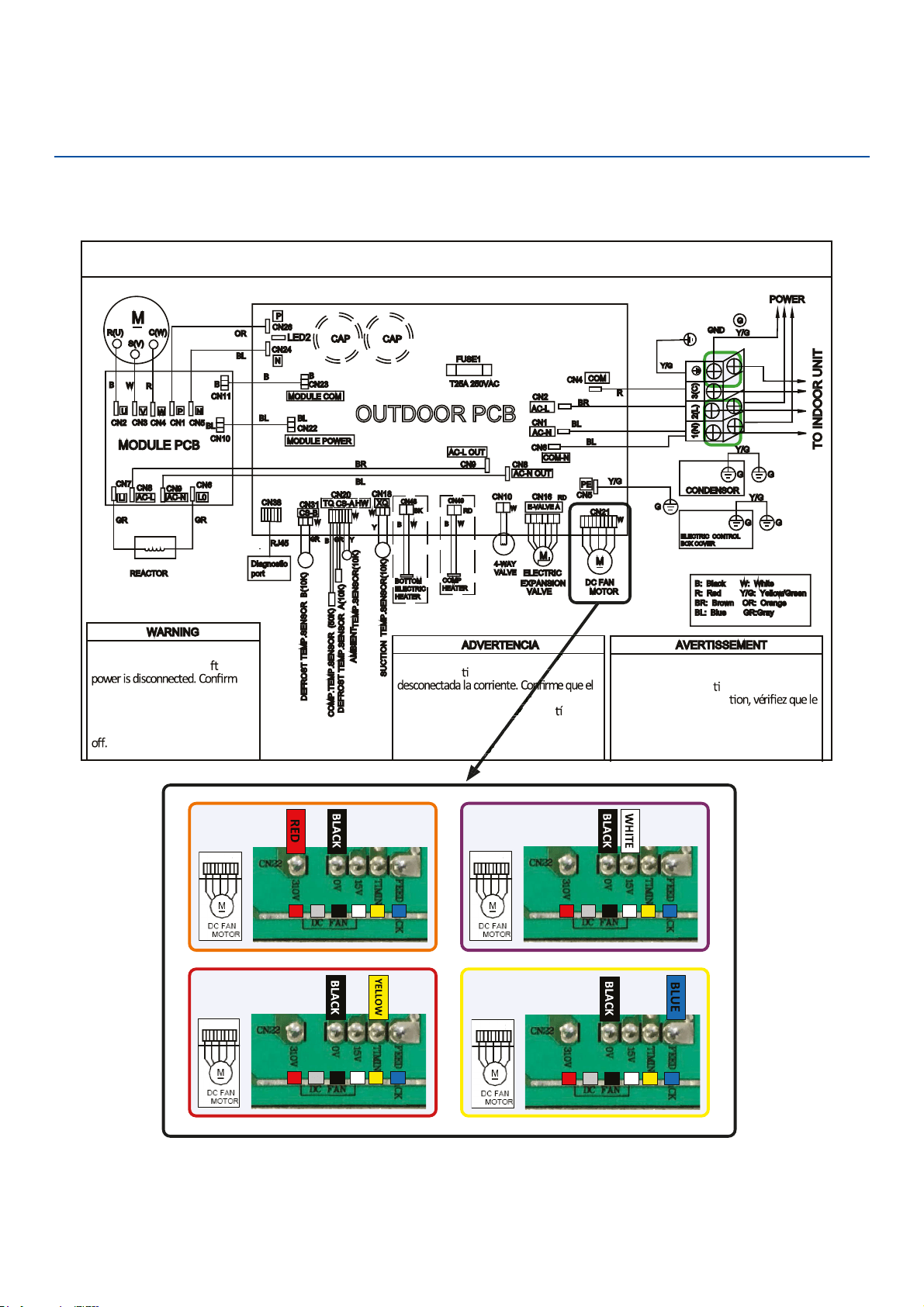
Troubleshooting
OUTD
●
OOR UNIT WIRING DIAGRAM
COMPRESSOR
Electrical Shock Hazard
●
Capacitor retains charge a er
voltage at capacitor has dissipated
(<10V DC) with hand held voltmeter
before servicing. LED2 light
between CN24 and CN26 should be
Riesgo de Descarga Eléctrica
El capacitor re
ene carga una vez
voltaje del capacitor se haya disipado (<10V
DC) apoyando la mano sobre el vol metro
antes de realizar el servicio técnico. La luz
LED2 que se encuentra entre CN24 y CN26
deberá estar apagada.
Risque de choc électrique
Le condensateur conserve sa charge après la
coupure de l’alimenta
on électrique. Avant
de procéder à une répara
courant au condensateur s’est dissipé
(<10 VCC) à l’aide d’un voltmètre manuel. Le
voyant LED2 entre CN24 et CN26 doit être
éteint.
0011509127
Error Code: F8/LED1: 9 Flash
Wiring Diagram Reference
Riesgo de Descarga Eléctrica
Riesgo de Descarga Eléctrica
ene carga una vez
voltaje del capacitor se haya disipado (<10V
sobre el
antes de realizar el servicio técnico. La luz
LED2 que se encuentra entre CN24 y CN
aga
da.
1 3
4
5
6
/
1 3
4
5
6
/
1 3
4
5
6
/
1 3
4
5
6
/
●
ERROR CODES and Troubleshooting
PAGE 90
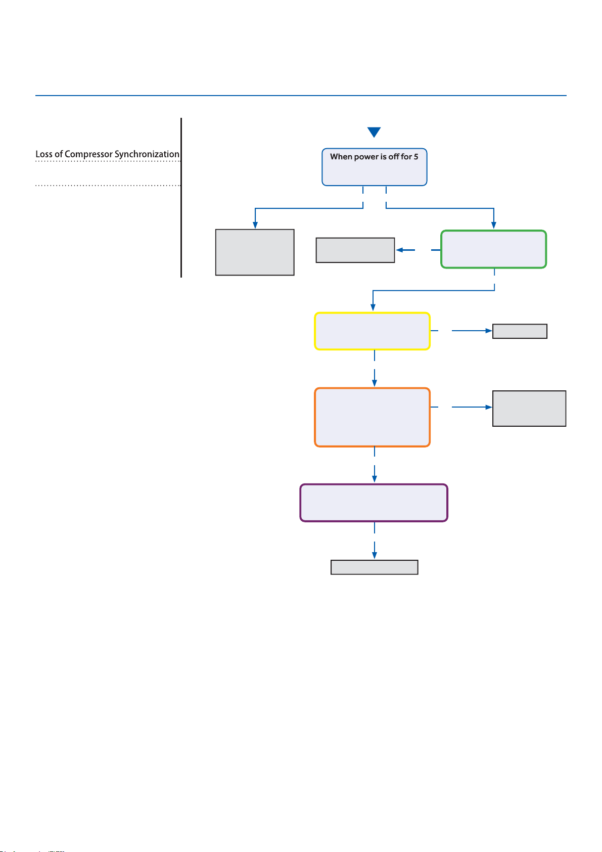
Troubleshooting
Start
See reverse side for
wiring diagram and
relevant color-coded
test positions.
No
●
No
Yes
Momentary loss
of building power
or acceptable
power quality
Replace
compressor
Replace compressor
●
Replace IPM
Repair or
replace wiring or
connections
min. and turned back on,
the compressor runs?
A windings or grounding
check shows issues with
compressor?
There is 50-200 VAC
across the U, V, and W
solder points on the IPM?
The compressor wires are
on the correct terminals,
free of breaks and the
connections at both end
are secure?
There is substantially more than
5 VDC or 15 VDC pulsing at CN23
(MODULE COM) on the PCB?
Yes
Yes
Yes
Yes
No
No
Error Code (Indoor/Outdoor)
F11/LED1: 18 Flash
Complete the “Check This First” Flow
Chart before continuing.
Models:
AW09EH2VHD/ASYW09URDWD
AW12EH2VHD/ASYW12URDWD
AW18EH2VHD/ASYW18URDWD
1U09EH2VHE/ASH109URDSE
1U12EH2VHE/ASH112URDSE
1U18EH2VHE/ASH118URDSE
ERROR CODES and Troubleshooting
PAGE 91
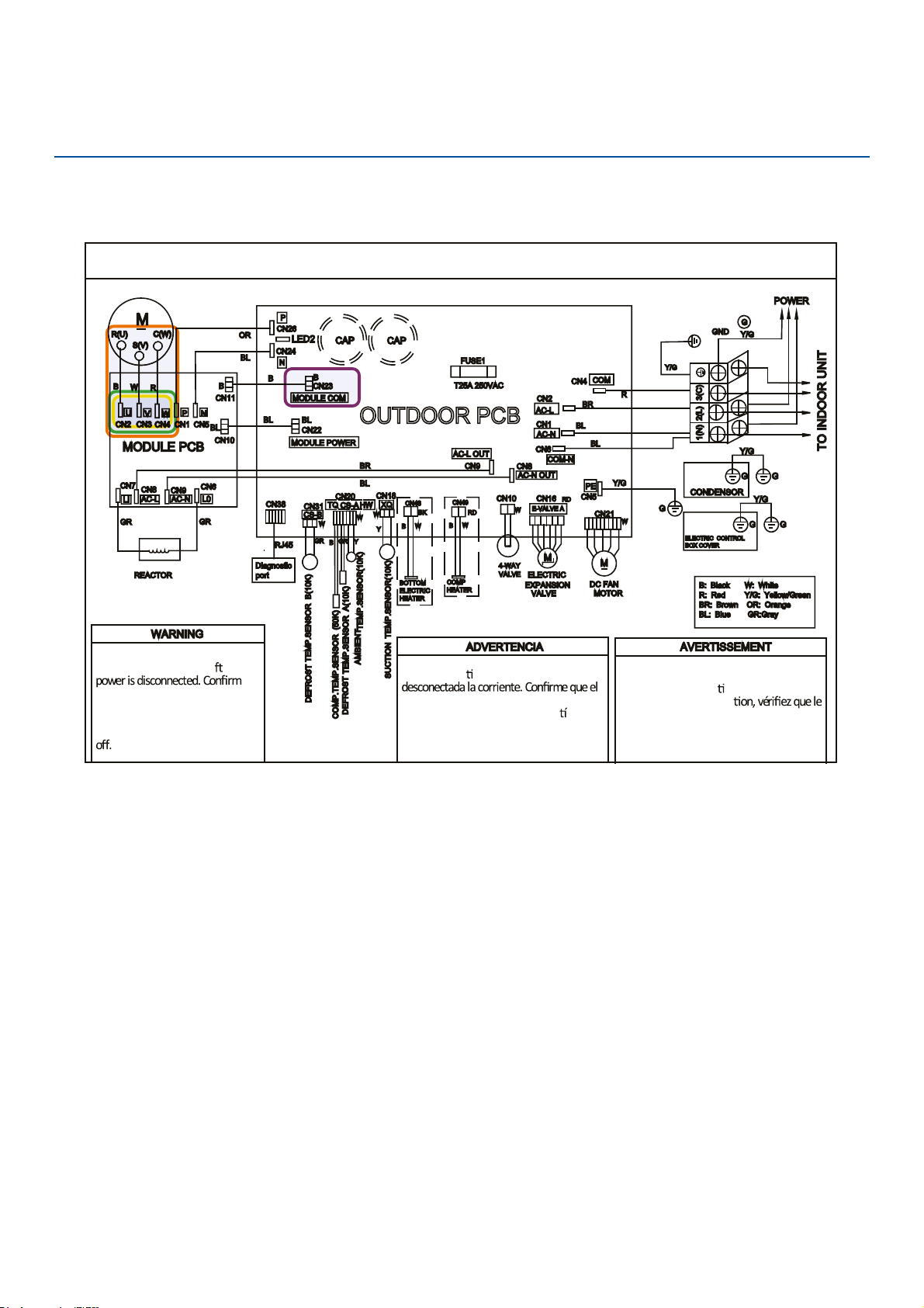
Troubleshooting
OUTD
●
OOR UNIT WIRING DIAGRAM
COMPRESSOR
Electrical Shock Hazard
●
Capacitor retains charge a er
voltage at capacitor has dissipa
●
ted
(<10V DC) with hand held voltmeter
before servicing. LED2 light
between CN24 and CN26 should be
Riesgo de Descarga Eléctrica
El capacitor re
ene carga una vez
voltaje del capacitor se haya disipado (<10V
DC) apoyando la mano sobre el vol metro
antes de realizar el servicio técnico. La luz
LED2 que se encuentra entre CN24 y CN26
deberá estar apagada.
Risque de choc électrique
Le condensateur conserve sa charge après la
coupure de l’alimenta
on électrique. Avant
de procéder à une répara
courant au condensateur s’est dissipé
(<10 VCC) à l’aide d’un voltmètre manuel. Le
voyant LED2 entre CN24 et CN26 doit être
éteint.
0011509127
Error Code: F11/LED1: 18 Flash
Wiring Diagram Reference
ERROR CODES and Troubleshooting
PAGE 92

Troubleshooting
Start
See reverse side for
wiring diagram and
relevant color-coded
test positions.
Yes
No
The 10-minute
reboot has
corrected the
issue
Replace PCB
After 10 minutes with the power
power turned back on?
Error Code (Indoor/Outdoor)
F12/LED1: 1 Flash
Complete the “Check This First” Flow
Chart before continuing.
Models:
AW09EH2VHD/ASYW09URDWD
AW12EH2VHD/ASYW12URDWD
AW18EH2VHD/ASYW18URDWD
1U09EH2VHE/ASH109URDSE
1U12EH2VHE/ASH112URDSE
1U18EH2VHE/ASH118URDSE
Wiring Diagram Reference
Outdoor Board Diagram
O
●
UTDOOR UNIT WIRING DIAGRAM
COMPRESSOR
Electrical Shock Haza
●
rd
Capacitor retains charge a
er
voltage at capacitor has diss
●
ipated
(<10V DC) with hand held vol
●
tmeter
before servicing. LED2 light
between CN24 and CN26 should be
Riesgo de Descarga Eléctrica
El capacitor re
ene carga una vez
voltaje del capacitor se haya disipado (<10V
DC) apoyando la mano sobre el vol metro
antes de realizar el servicio técnico. La luz
LED2 que se encuentra entre CN24 y CN26
deberá estar apagada.
Risque de choc électrique
Le condensateur conserve sa charge après la
coupure de l’alimenta
on électrique. Avant
de procéder à une répara
courant au condensateur s’est dissipé
(<10 VCC) à l’aide d’un voltmètre manuel. Le
voyant LED2 entre CN24 et CN26 doit être
éteint.
0011509127
ERROR CODES and Troubleshooting
PAGE 93
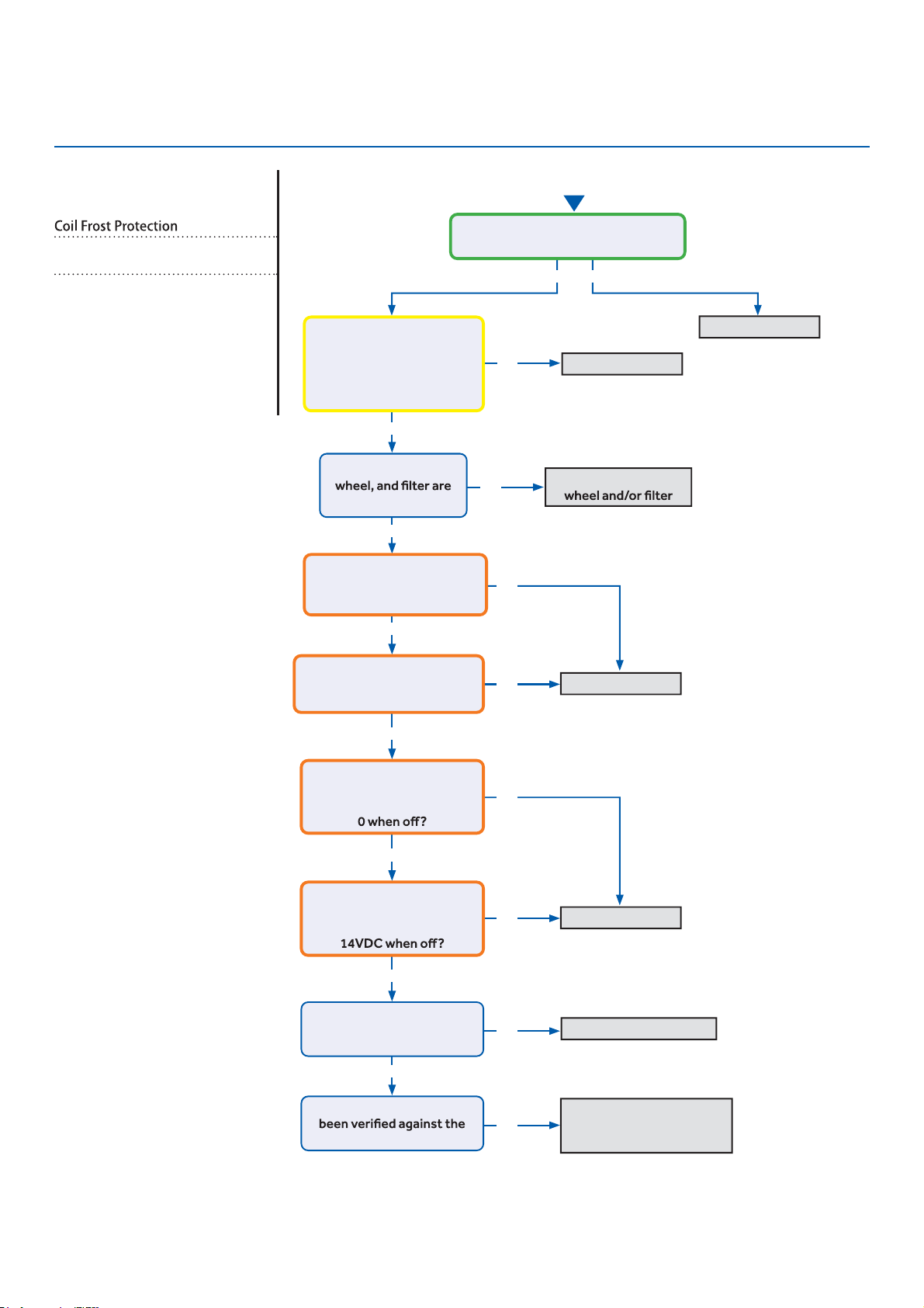
Troubleshooting
Start
See reverse side for
wiring diagram and
relevant color-coded
test positions.
Yes
●
Yes
●
Yes
Yes
Yes
●
Yes
●
Yes
●
No
No
No
No
No
No
No
No
Yes No
Replace PCB
Replace PCB
Replace Motor
Replace/Repair EEV Coil
Recover refrigerant, check
for leaks, evacuate, and
re-charge per nameplate
Replace sensor
Wash coil, blower
There is 5 VDC at CN6 on the Indoor
PCB across the black senor wires?
The Coil and Ambient
Sensors’ resistances are
within 3% of the value
listed in the Service Manual
sensor resistance table?
The coil, blower
free of dirt or debris?
There is DCV at the motor
PCB connections:
RD to BK: 310-334VDC?
There is DCV at the motor
PCB connections:
WH to BK: 15VDC
There is DCV at the motor
PCB connections:
YL to BK: 1-4VDC running,
There is DCV at the motor
PCB connections:
BL to BK: 4-8VDC running,
Is the EEV coil properly
seated and the coil
resistance correct?
The refrigerant charge has
nameplate value?
Error Code (Indoor/Outdoor)
E5/LED1: 22 Flash
Complete the “Check This First” Flow
Chart before continuing.
Models:
AW09EH2VHD/ASYW09URDWD
AW12EH2VHD/ASYW12URDWD
AW18EH2VHD/ASYW18URDWD
1U09EH2VHE/ASH109URDSE
1U12EH2VHE/ASH112URDSE
1U18EH2VHE/ASH118URDSE
ERROR CODES and Troubleshooting
PAGE 94
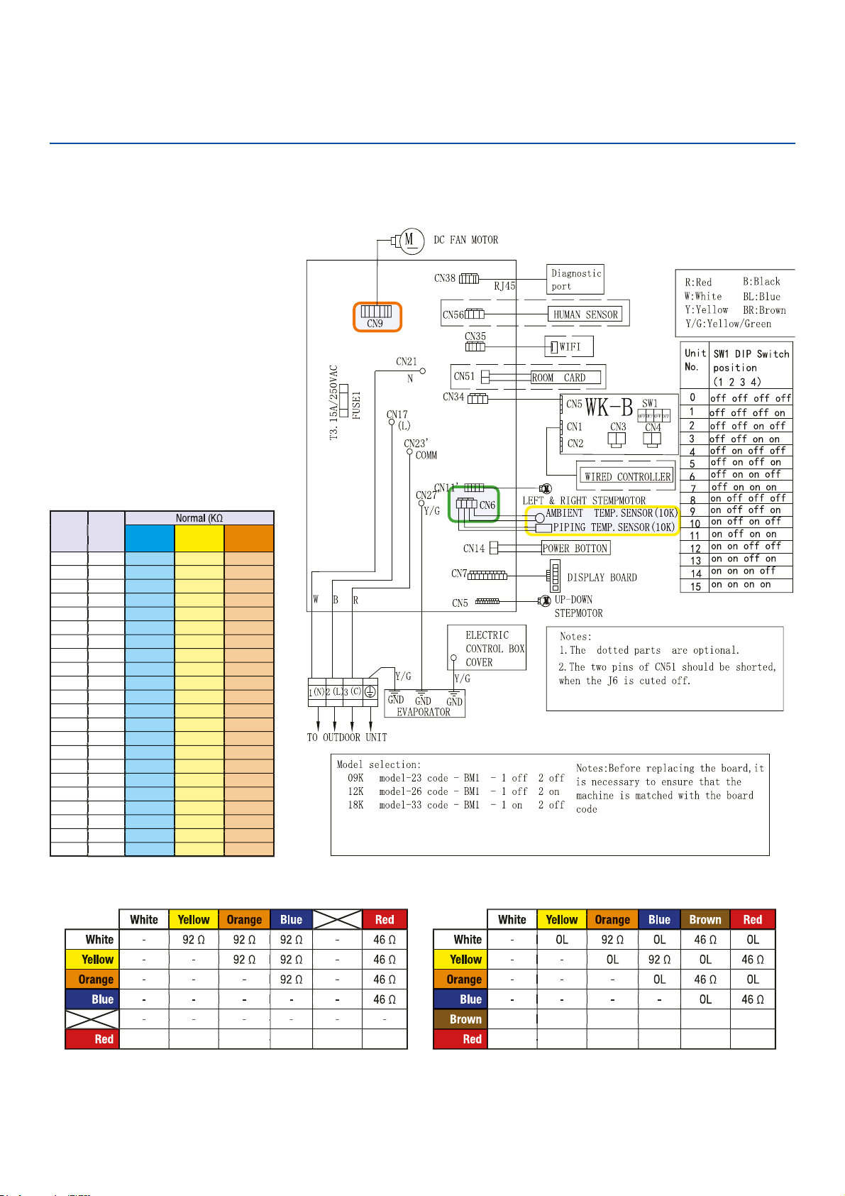
Troubleshooting
Error Code: E5/LED1: 22 Flash
Wiring Diagram Reference
Sensor Resistance Table
EEV Resistance Values
EEV (6-pin, 6 wire)
EEV (6-pin, 5 wire)
ERROR CODES and Troubleshooting
PAGE 95
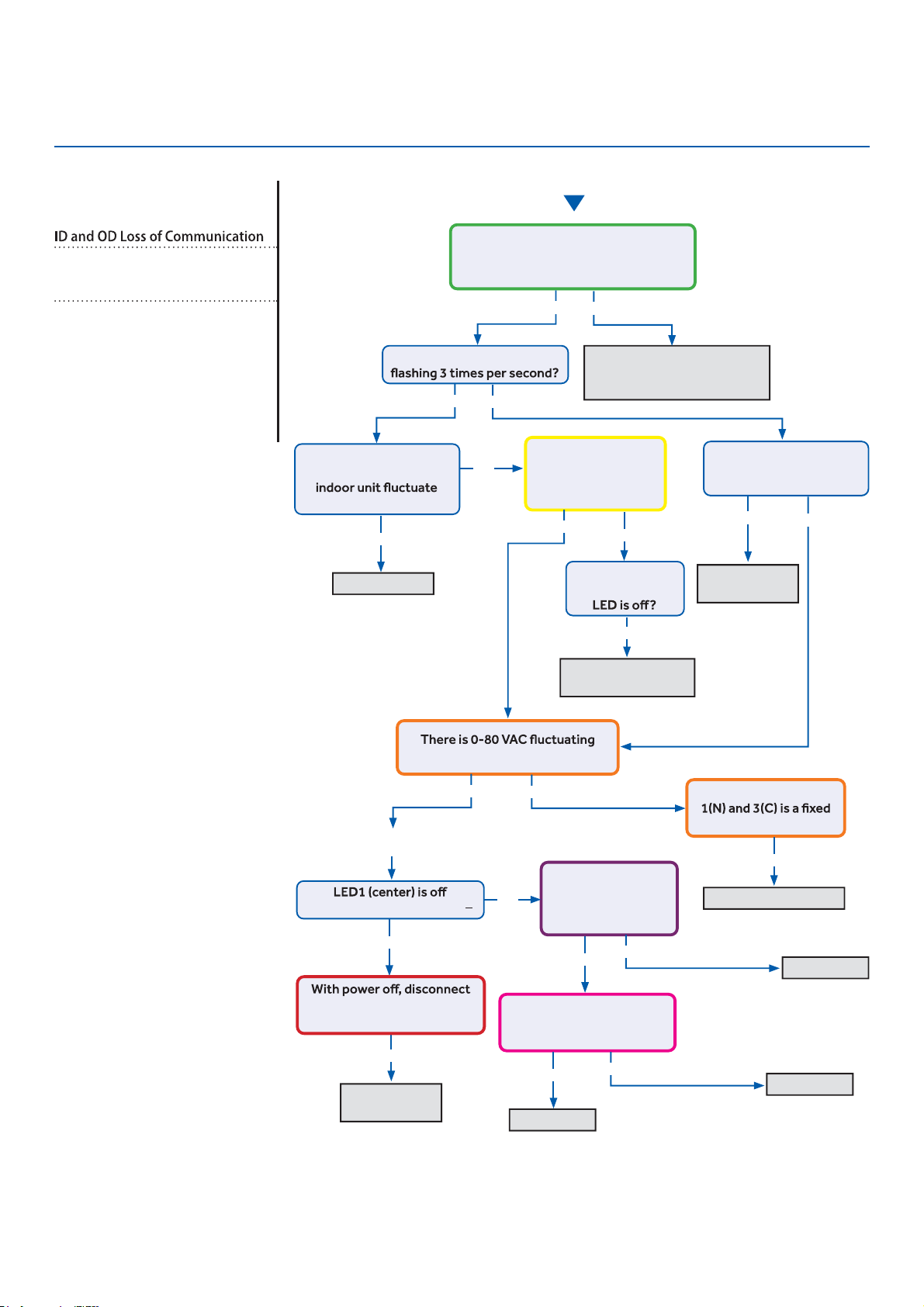
Troubleshooting
Start
●
See reverse side for
wiring diagram and
relevant color-coded
test positions.
Reposition on correct
●
terminals, replace wire if
spliced or the incorrect type
Indoor PCB OK
●
The control wire is 14/4 stranded
copper on the correct terminals, with
no splices or loose connections?
Yes
No
Yes
Yes
No
No
Is the Indoor PCB LED
Does the voltage
between L and C at
0~140VAC?
Is the voltage from
L to C at indoor unit
between 0~80VAC
(approx..)?
Is the Indoor PCB LED
pattern repeatedly
Flash…Flash…On?
Fault is with
outdoor PCB
Replace fan
●
motor
Replace INDOOR PCB
Replace PCB
Replace PCB
Replace IPM
The communication
wire is broken
between 1(N) and 3(C) at ID UNIT?
There is 230 VAC
at the PCB? Across
AC-L OUT & AC-N
OUT (CN9 & CN8)
There is less than 5 VDC at
CN22 (module power) and
GND (pins 1 and 2)?
The voltage between
value at ID UNIT?
Go to outdoor PCB
No
Yes
Yes
Yes
Yes
Yes
Yes
Yes
No
No
Yes
Yes
No
No
No
LED2 (upper left) is lighted?
fan motor at CN21. LED1
lights with power back on?
The display is
lighted, yet the
Error Code (Indoor/Outdoor)
E7/LED1: 15 Flash
Complete the “Check This First” Flow
Chart for both ID and OD units before
continuing.
Models:
AW09EH2VHD/ASYW09URDWD
AW12EH2VHD/ASYW12URDWD
AW18EH2VHD/ASYW18URDWD
1U09EH2VHE/ASH109URDSE
1U12EH2VHE/ASH112URDSE
1U18EH2VHE/ASH118URDSE
ERROR CODES and Troubleshooting
PAGE 96
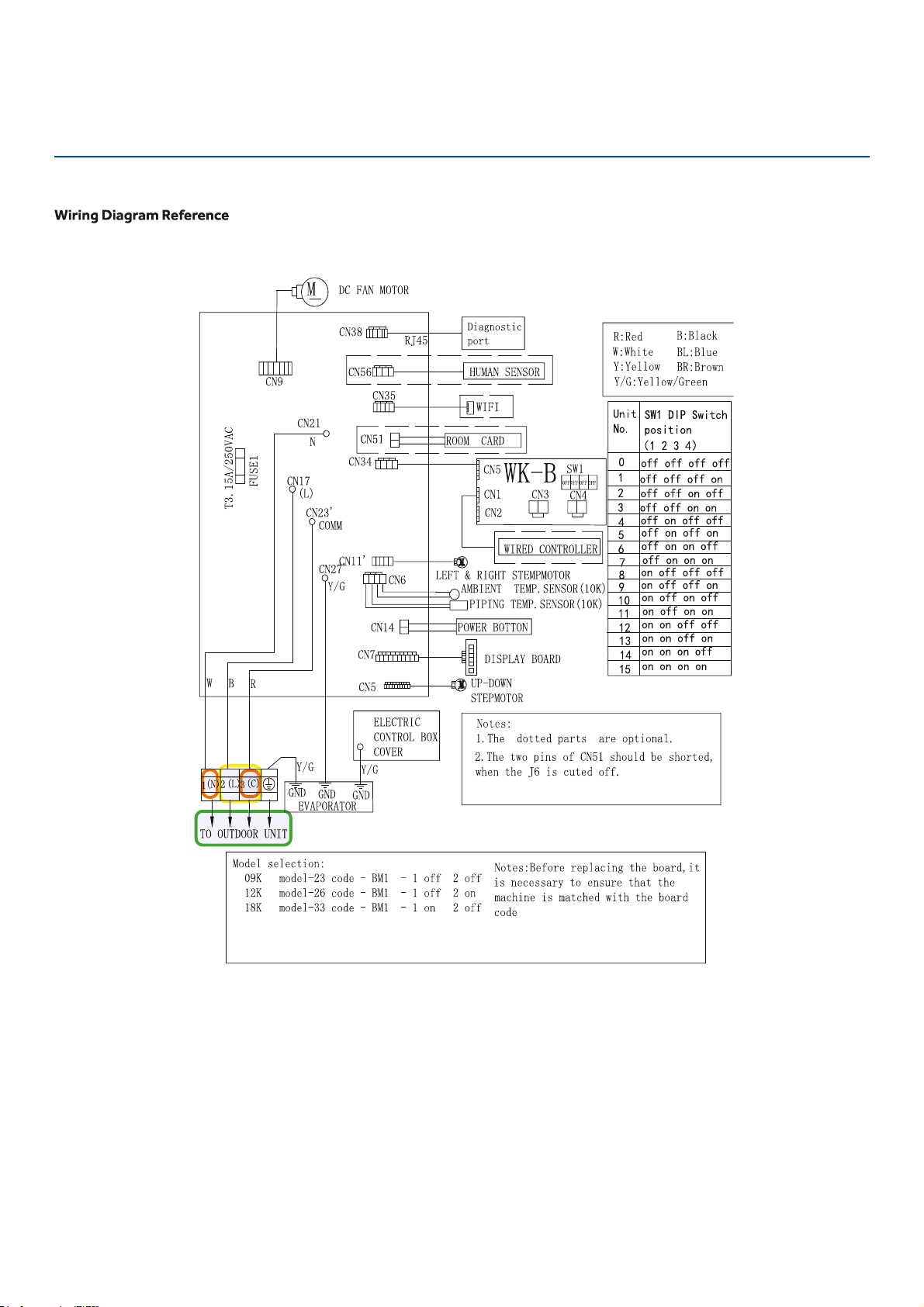
Troubleshooting
Error Code: E7/LED1: 15 Flash
ERROR CODES and Troubleshooting
PAGE 97
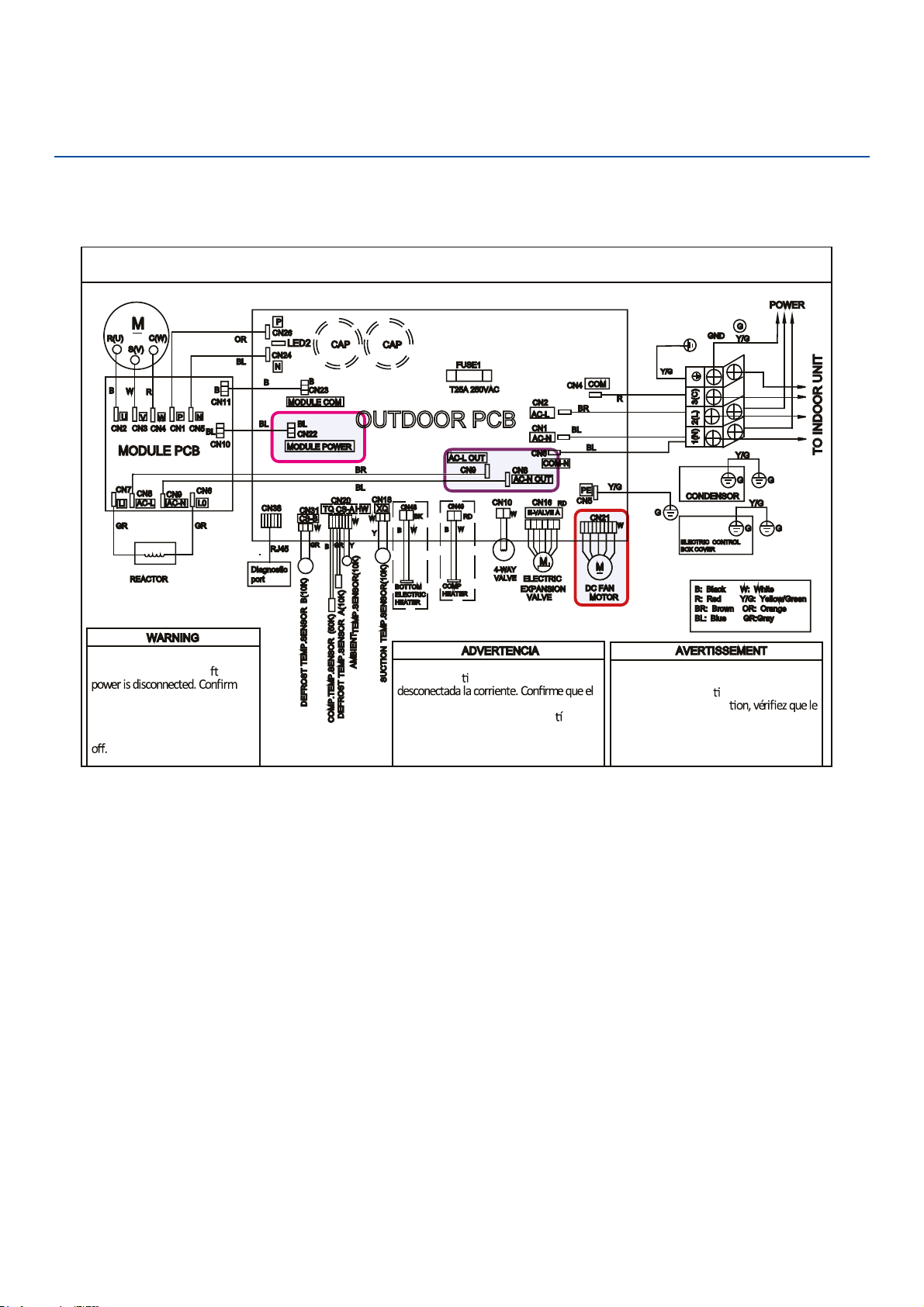
Troubleshooting
OUTDOOR UNIT WIRING DIAGRAM
COMPRESSOR
Electrical Shock Hazard
Capacitor retains charge a
er
voltage at capacitor has dissipated
(<10V DC) with hand held voltmeter
before servicing. LED2 light
between CN24 and CN26 should be
Riesgo de Descarga Eléctrica
El capacitor re
ene carga una vez
voltaje del capacitor se haya disipado (<10V
DC) apoyando la mano sobre el vol
metro
antes de realizar el servicio técnico. La luz
LED2 que se encuentra entre CN24 y CN26
deberá estar apagada.
Risque de choc électrique
Le condensateur conserve sa charge après la
coupure de l’alimenta
on électrique. Avant
de procéder à une répara
courant au condensateur s’est dissipé
(<10 VCC) à l’aide d’un voltmètre manuel. Le
voyant LED2 entre CN24 et CN26 doit être
éteint.
0011509127
Error Code: E7/LED1: 15 Flash
Wiring Diagram Reference
ERROR CODES and Troubleshooting
PAGE 98
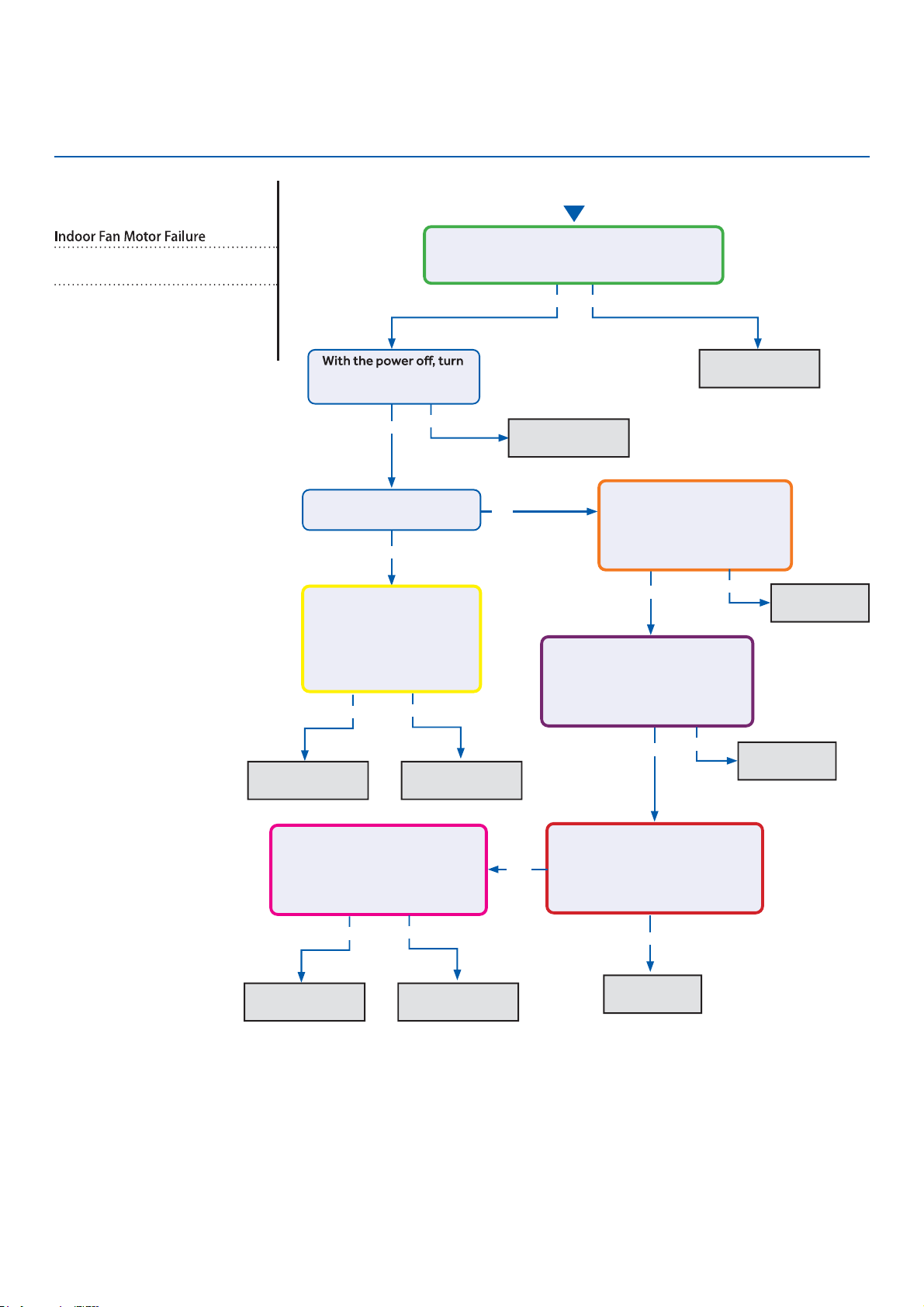
Troubleshooting
See reverse side for
wiring diagram and
relevant color-coded
test positions.
Error Code (Indoor)
E14
Complete the “Check This First” Flow
Chart before continuing.
Models:
AW09EH2VHD/ASYW09URDWD
AW12EH2VHD/ASYW12URDWD
AW18EH2VHD/ASYW18URDWD
Yes
●
Yes
●
Yes
Yes
No
Yes No
No
Fix incoming
power supply
Replace the fan
motor
Replace the main
board.
Replace the fan
motor
Replace the
main board.
Replace the
main board.
Replace the
●
main board.
Start
the fan by hand. Does it
move / rotate smootly?
Check the incoming voltage. Is it 208/230VAC
(+/- 10%) between L1/L2? 104/115VAC (+/-
10%) from L1 to GROUND and L2 to GROUND?
Re-apply power. Does the
fan come on and spin?
Measure DC voltage at fan
motor plug CN9 between
the Pin 7 (BLUE) and Pin
4 (BLACK) wire while
spinning the fan motor.
Does it generate 2~9VDC?
Measure DC voltage at fan
motor plug CN9 between Pin
1 (RED) and Pin 4 (BLACK).
Does it measure 300~380VDC
(+/-10%)?
Measure DC voltage at fan motor
plug CN9 between Pin 5 (WHITE)
and Pin 4 (BLACK).
Does it measure between
13.5-16.5VDC?
No
No
No
Yes
Replace the main
board.
Replace the fan
motor
Measure DC voltage at fan
motor plug CN9 between Pin 6
(YELLOW) and Pin 4 (BLACK).
Does it measure between
2-6VDC?
Measure DC voltage at fan motor
plug CN9 between the Pin 7
(BLUE) and Pin 4 (BLACK) wire
while spinning the fan motor.
Does it generate 2~9VDC?
No
Yes
No
Yes
ERROR CODES and Troubleshooting
●
PAGE 99
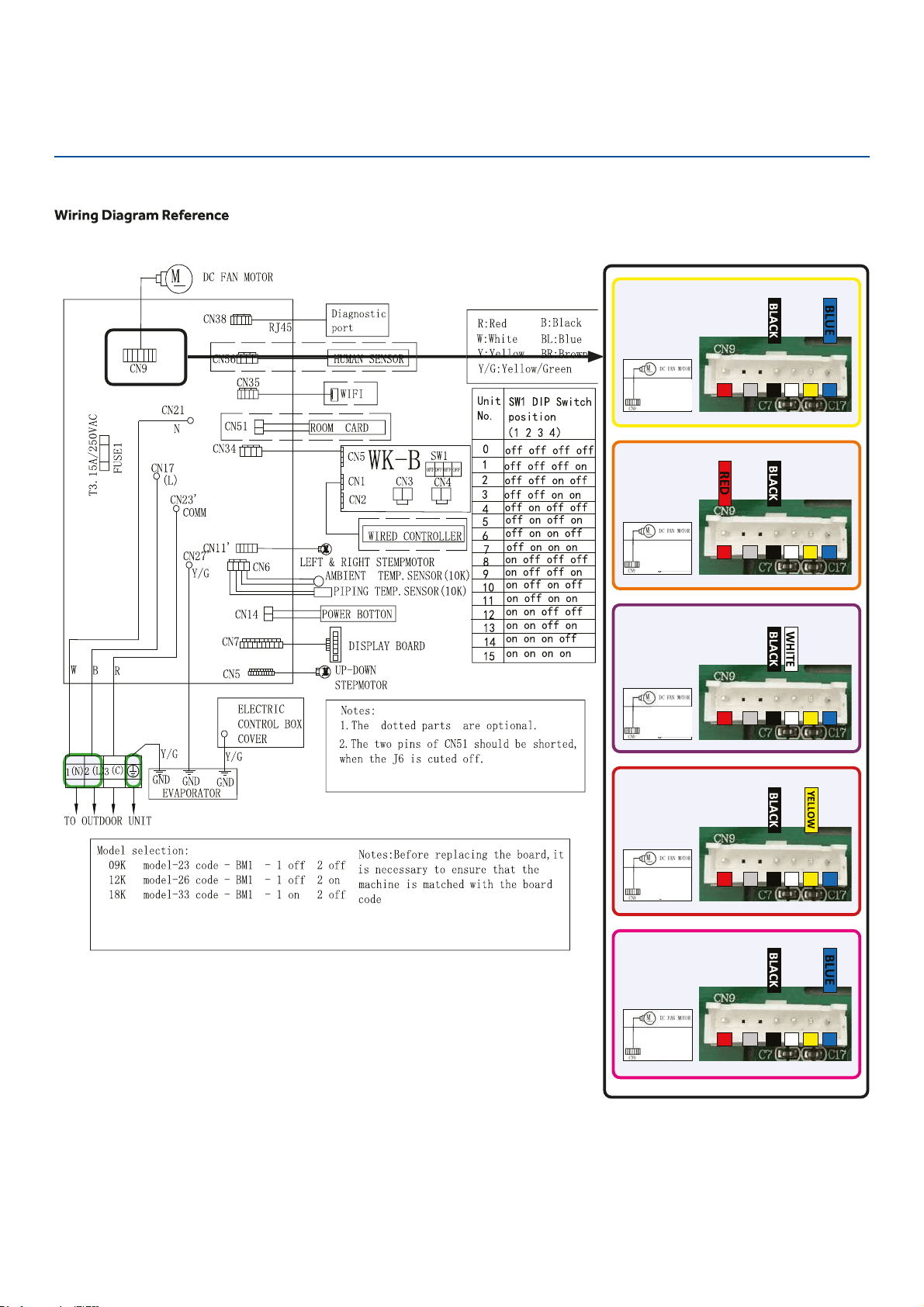
Troubleshooting
Error Code: E14
1
4
5 6/ 7
1
4
5 6/ 7
1
4
5 6/ 7
1
4
5 6/ 7
1
4
5 6/ 7
ERROR CODES and Troubleshooting
PAGE 100
Troubleshooting
Checking System Components
Checking Outdoor Unit Components
NOTE: Component resistance readings shown in this section
are for reference only. Actual resistance values may
based on model being tested.
Component readings shown below are based on the models
of 1U*EH2VHD outdoor unit.
Step 3
Re-seat the plug on the connector at the conclusion of the
test.
Checking the EEV Coil
Step 1
Disconnect the EEV coil from the PCB for this test. Failure
to do so may provide inaccurate readings.
Step 2
The resistance values of plus pin combinations are 46 Ohm.
Step 3
Re-seat the plug on the connector at the conclusion of the
test.
Testing of the following components requires the use of
needle probes. Avoid testing the connector end of the plug,
as damage to the internal sections of the plug can occur.
Checking the Outdoor Unit Sensors
NOTE: Use respective temperature / sensor chart for sensor
type being tested.
Compressor discharge sensor
Suction sensor
Defrost temperature sensor
Ambient sensor
Step 1
Disconnect the sensor plug from the control board for this
test. Failure to do so may provide inaccurate readings.
Step 2
Using k-type temperature probe, determine the temperature
of the sensor being tested.
Step 3
Using an ohmmeter, check the resistance value of the sensor.
Step 4
Referring to the temperature / resistance table for the sensor
being checked, verify the resistance value corresponds to the
temperature checked in Step 2.
Replace the sensor if the reading is open, shorted, or outside
Step 5
Re-seat the plug on the connector at the conclusion of the
test.
Checking the Reversing Valve Coil
Step 1
Disconnect the reversing valve plug from the PCB
for this test. Failure to do so may provide inaccurate read-
ings.
Step 2
Using an ohmmeter, check the resistance value of the coil.
The resistance value of the coil should be 1.2 kilo ohms to
1.8 kilo ohms. Replace the valve c
ERROR CODES and Troubleshooting
●
Checking the DC Fan Motor
Step 1
Using needle probes, check the DCV at the back of the fan plug on
the PCB. The values are:
Red to black: +310 VDC
White to black: +15 VDC
Yellow to black: 1-4 VDC when running; 0 VDC when there is no call
for heating or cooling
Blue to black: pulsing 0-8 VDC when running; 14 VDC when there is
no call for heating or cooling
Checking the Compressor Windings
Step 1
Disconnect wiring from terminals U, V and W of the IPM.
Step 1
Using an Ohmmeter, check the resistance value of the
compressor windings. Measure between wires U and V,
U and W, and V, and W.
The resistance value of the windings should be balanced
(equal). If the resistance values are not equal, verify the
wiring and connections to the compressor as well as the
compressor itself. Repair or replace as needed.
PAGE 101
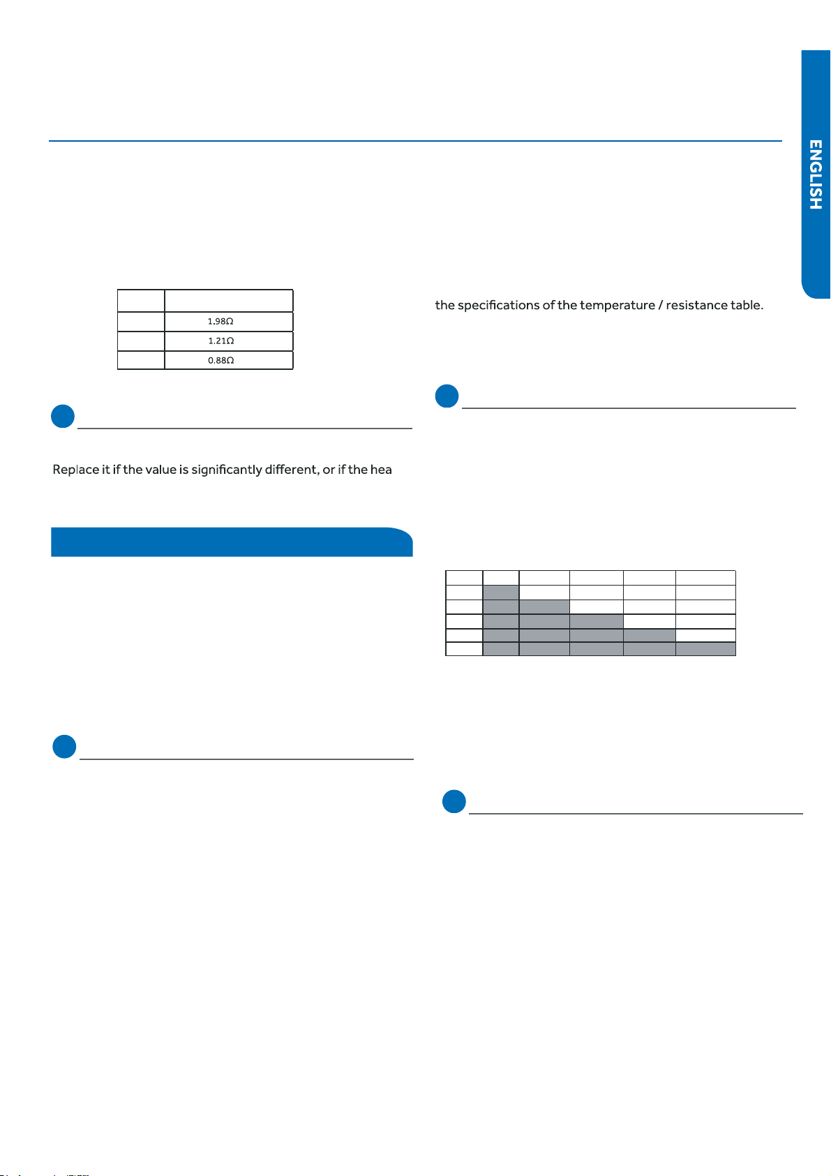
Troubleshooting
Step 3
Reconnect the wiring to the IPM at the conclusion of the
test.
NOTE: Resistance readings shown in this section are for
reference only
type being tested.
Coil sensor
Ambient sensor
Step 1
Disconnect the sensor from the PCB for this test. Failure to
do so may provide
inaccurate readings.
Step 2
Determine the temperature of the sensor being tested.
Step 3
Check the resistance value of the sensor.
Step 4
Referring to the temperature / resistance table for the sensor
being checked, verify the resistance value corresponds to the
temperature checked in step 2.
Replace the sensor if the reading is open, shorted, or outside
Step 5
Re-seat the plug on the PCB at the conclusion of the test.
Checking the Up/Down Stepper Motor
Step 1
Disconnect the Up/Down Stepper Motor plug PCB for the test.
Failure to do so may provide inaccurate readings.
NOTE: When using the test probes, probe the back or side
contacts of the plug to obtain the reading. Do not try to
probe the connector end of the plug, as this may damage the
contacts.
Checking the Indoor Unit Sensors
NOTE: Use respective temperature / sensor chart for sensor
Testing of the following components requires the use of an
ohmmeter and k-type temperature probe.
Checking Indoor Unit Components
Checking the Base Pan Heater
The resistance across the heater should be 100 to 500 ohms.
ter
reads open or shorted.
Winding resistance
09K
12K
18K
Model
ERROR CODES and Troubleshooting
Step 2
Refer to the chart shown below for plug pin combinations and
resistance values.
Step 3
Re-seat the plug on the connector at the conclusion of the
test.
Red Orange Yellow Pink
Blue
Red 296.5Ohm 295.5 Ohm 296.3 Ohm
296.1 Ohm
Orange 594.5 Ohm 595.5 Ohm
594.5 Ohm
Yellow 594.3 Ohm
594.5 Ohm
Pink 594.3 Ohm
Blue
Step 1
Disconnect the Motor plug from the PCB for this test. Failure
to do so may provide inaccurate readings.
Left/Right Stepper Motor eht gnikcehC
PAGE 102
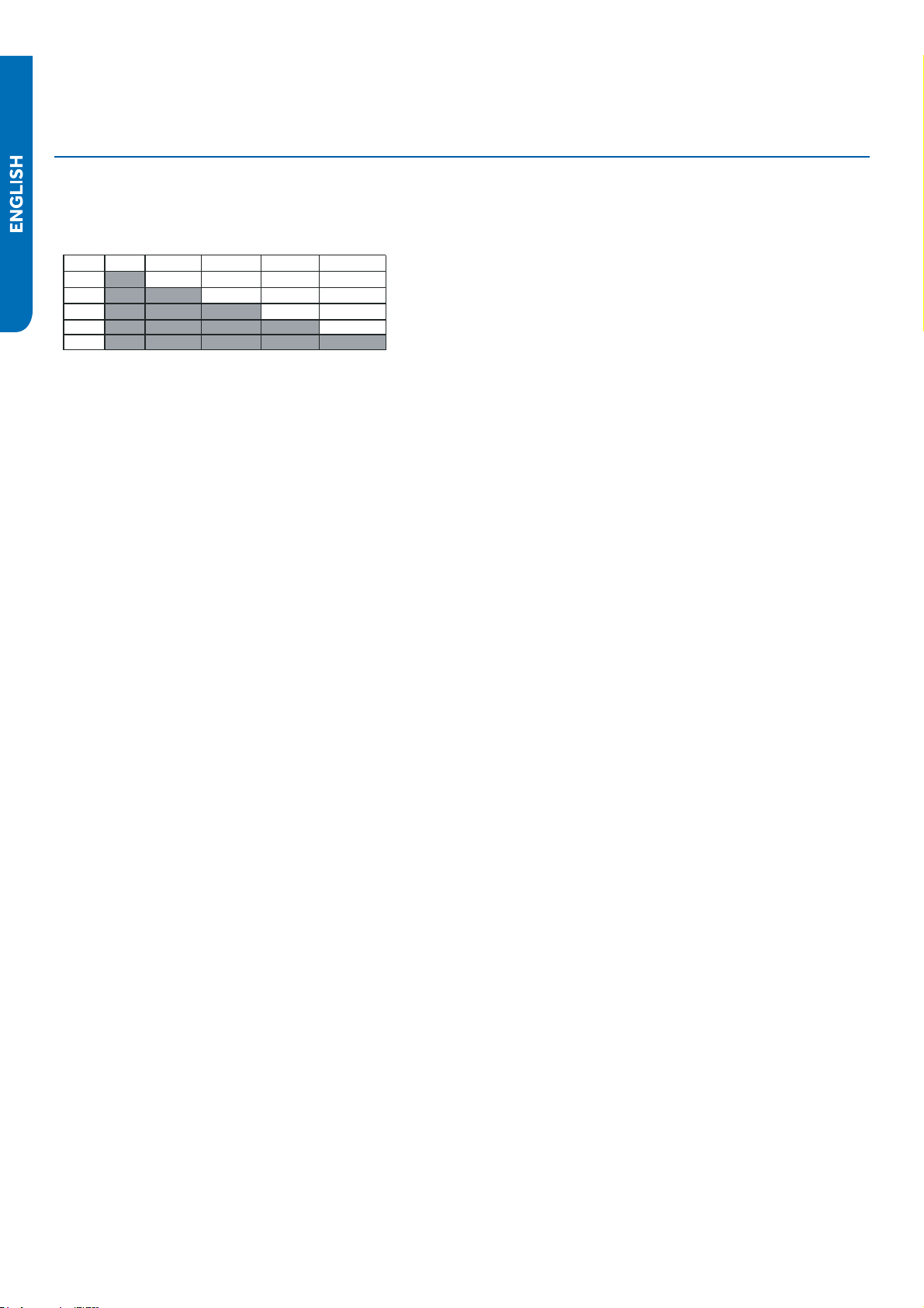
Troubleshooting
Red Orange Yellow Pink
Blue
Red 296.5Ohm 295.5 Ohm 296.3 Ohm
296.1 Ohm
Orange 594.5 Ohm 595.5 Ohm
594.5 Ohm
Yellow 594.3 Ohm
594.5 Ohm
Pink 594.3 Ohm
Blue
Step 3
Re-seat the plug on the PCB at the conclusion of the test.
Step 2
Refer to the chart shown below for plug pin combinations and
resistance values.
ERROR CODES and Troubleshooting
PAGE 103
Ambient, Defrost, and Pipe Sensor Tables
Discharge Sensor Tables
105
106
107
110
113
PAGE 104
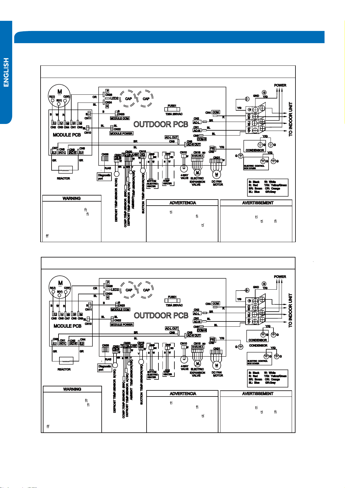
Outdoor Board Diagram
09K
12K-18K
●
OUTDOOR UNIT WIRING DIAGRAM
COMPRESSOR
Electrical Shock Hazard
●
Capacitor retains charge a er
power is disconnected. Con rm
voltage at capacitor has dissipated
(<10V DC) with hand held voltmeter
before servicing. LED2 light
between CN24 and CN26 should be
●
o .
Riesgo de Descarga Eléctrica
El capacitor re
ene carga una vez
desconectada la corriente. Con rme que el
voltaje del capacitor se haya disipado (<10V
DC) apoyando la mano sobre el vol
metro
antes de realizar el servicio técnico. La luz
LED2 que se encuentra entre CN24 y CN26
deberá estar apagada.
Risque de choc électrique
Le condensateur conserve sa charge après la
coupure de l’alimenta
on électrique. Avant
de procéder à une répara
on, véri ez que le
courant au condensateur s’est dissipé
(<10 VCC) à l’aide d’un voltmètre manuel. Le
voyant LED2 entre CN24 et CN26 doit être
éteint.
0011509127A
OUTDOOR UNIT WIRING DIAGRAM
COMPRESSOR
Electrical Shock Hazard
Capacitor retains charge a
er
power is disconnected. Con
rm
voltage at capacitor has dissipated
(<10V DC) with hand held voltmeter
before servicing. LED2 light
between CN24 and CN26 should be
o
.
Riesgo de Descarga Eléctrica
El capacitor re
ene carga una vez
desconectada la corriente. Con rme que el
voltaje del capacitor se haya disipado (<10V
DC) apoyando la mano sobre el vol
metro
antes de realizar el servicio técnico. La luz
LED2 que se encuentra entre CN24 y CN26
deberá estar apagada.
Risque de choc électrique
Le condensateur conserve sa charge après la
coupure de l’alimenta
on électrique. Avant
de procéder à une répara
on, véri ez que le
courant au condensateur s’est dissipé
(<10 VCC) à l’aide d’un voltmètre manuel. Le
voyant LED2 entre CN24 et CN26 doit être
éteint.
0011509127
REFERENCE INFORMATION
PAGE 105
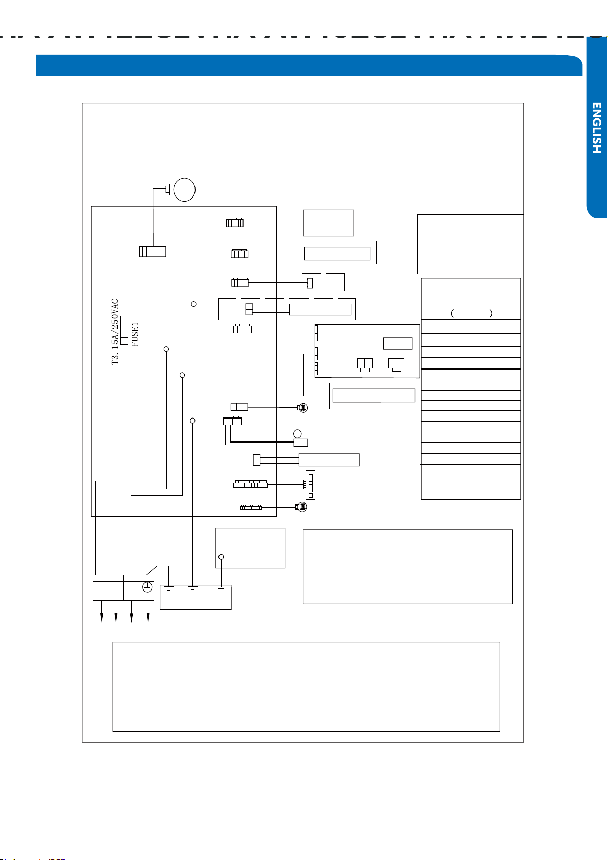
Indoor Board Diagram
R:Red
W:White
Y:Yellow
Y/G:Yellow/Green
B:Black
BR:Brown
BL:Blue
PIPING TEMP.SENSOR(10K)
AMBIENT TEMP.SENSOR(10K)
POWER BOTTON
INDOOR UNIT DIAGRAM
Notes:
1.The dotted parts are optional.
2.The two pins of CN51 should be shorted,
when the J6 is cuted off.
M
CN7
TO OUTDOOR UNIT
1
(N)
(C)
3
(L)
2
W
B
Y/G
GND
CN6
R
(L)
CN21
N
COMM
CN51
CN9
CN17
CN23'
CN35
CN34
ROOM CARD
CN5
DC FAN MOTOR
CN11'
DISPLAY BOARD
Model selection:
09K model-23 code - BM1 - 1 off 2 off
12K model-26 code - BM1 - 1 off 2 on
18K model-33 code - BM1 - 1 on 2 off
WIRED CONTROLLER
UP-DOWN
STEPMOTOR
LEFT & RIGHT STEMPMOTOR
WIFI
CN14
Notes:Before replacing the board,it
is necessary to ensure that the
machine is matched with the board
code
CN56
HUMAN SENSOR
CN38
CN27'
Y/G
GND
0011509128
WK-B
EVAPORATOR
ELECTRIC
CONTROL BOX
COVER
GND
Y/G
RJ45
Diagnostic
port
CN5
CN1
CN2
SW1
OFF
OFF
OFF
OFF
CN3
CN4
Unit
No.
SW1 DIP Switch
position
1 2 3 4
1
2
3
4
5
6
7
8
9
10
11
12
13
14
15
off off off off
off off off on
off off on off
off off on on
off on off on
off on on off
off on on on
on off off off
on off off on
on off on off
on off on on
on on off off
on on off on
on on on off
on on on on
0
off on off off
REFERENCE INFORMATION
PAGE 106

Room and Coil Sensor Tables
.pmeTF° .pmeT °C M ) ) ) Tolerance (°C)
-22 -30 165.217 147.9497 132.3678 -1.94 1.75
-20.2 -29 155.5754 139.56 125.0806 -1.93 1.74
-18.4 -28 146.5609 131.7022 118.2434 -1.91 1.73
-16.6 -27 138.1285 124.3392 111.8256 -1.89 1.71
-14.8 -26 130.2371 117.4366 105.7989 -1.87 1.7
-13 -25 122.8484 110.9627 100.1367 -1.85 1.69
-11.2 -24 115.9272 104.8882 94.8149 -1.83 1.67
-9.4 -23 109.441 99.1858 89.8106 -1.81 1.66
-7.6 -22 103.3598 93.8305 85.1031 -1.8 1.64
-5.8 -21 97.6556 88.7989 80.6728 -1.78 1.63
-4 -20 92.3028 84.0695 76.5017 -1.76 1.62
-2.2 -19 87.2775 79.6222 72.5729 -1.74 1.6
-0.4 -18 82.5577 75.4384 68.871 -1.72 1.59
1.4 -17 78.123 71.501 65.3815 -1.7 1.57
3.2 -16 73.9543 67.7939 62.0907 -1.68 1.55
5 -15 70.0342 64.3023 58.9863 -1.66 1.54
6.8 -14
●
66.3463 61.0123 56.0565 -1.64 1.52
8.6 -13 62.8755 57.911 53.2905 -1.62 1.51
10.4 -12 59.6076 54.9866 50.6781 -1.6 1.49
12.2 -11
●
56.5296 52.2278 48.2099 -1.58 1.47
14 -10 53.6294 49.6244 45.8771 -1.56 1.46
15.8 -9 50.8956 47.1666 43.6714 -1.54 1.44
17.6 -8 48.3178 44.8454 41.5851 -1.51 1.42
19.4 -7 45.886 42.6525 39.6112 -1.49 1.4
21.2 -6
●
43.5912 40.58 37.7429 -1.47 1.39
23 -5 41.4249 38.6207 35.9739 -1.45 1.37
24.8 -4
●
39.3792 36.7676 34.2983 -1.43 1.35
26.6 -3 37.4465 35.0144 32.7108 -1.41 1.33
28.4
●
-2 35.6202 33.3552 31.2062 -1.38 1.31
30.2 -1 33.8936 31.7844 29.7796 -1.36 1.29
32 0 32.2608 30.2968 28.4267 -1.34 1.28
33.8 1 30.7162 28.8875 27.1431 -1.32 1.26
35.6 2 29.2545 27.5519 25.925 -1.29 1.24
37.4 3 27.8708 26.2858 24.7686 -1.27 1.22
39.2 4 26.5605 25.0851 23.6704 -1.25 1.2
41 5 25.3193 23.9462 22.6273 -1.23 1.18
42.8 6 24.1432 22.8656 21.6361 -1.2 1.16
44.6 7 23.0284 21.8398 20.6939 -1.18 1.14
46.4 8 21.9714 20.8659 19.7982 -1.15 1.12
48.2 9 20.9688 19.9409 18.9463 -1.13 1.09
50 10 20.0176 19.0621 18.1358 -1.11 1.07
51.8 11 19.1149 18.227 17.3646 -1.08 1.05
53.6 12 18.258 17.4331 16.6305 -1.06 1.03
55.4 13 17.4442 16.6782 15.9315 -1.03 1.01
57.2 14 16.6711 15.9601 15.2657 -1.01 0.99
59 15 15.9366 15.277 14.6315 -0.98 0.96
60.8 16 15.2385 14.6268 14.0271 -0.96 0.94
R77° =
B77°/122° =
REFERENCE INFORMATION
PAGE 107
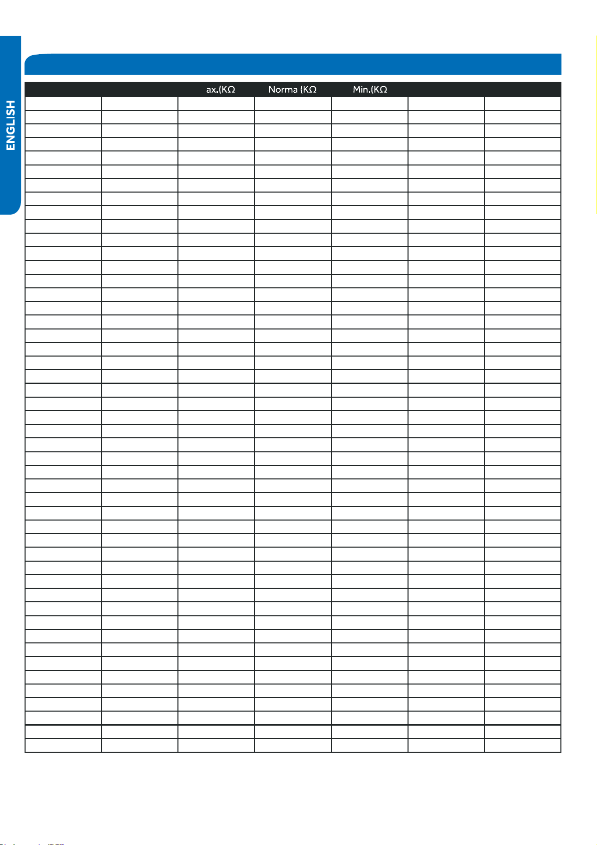
Room and Coil Sensor Tables
.pmeTF° .pmeT °C M ) ) ) Tolerance (°C)
62.6 17 14.5748 14.0079 13.451 -0.93 0.92
64.4 18 13.9436 13.4185 12.9017 -0.91 0.9
66.2 19 13.3431 12.8572 12.3778 -0.88 0.87
68 20 12.7718 12.3223 11.878 -0.86 0.85
69.8 21 12.228
●
11.8126 11.4011 -0.83 0.83
71.6 22 11.7102 11.3267 10.9459 -0.81 0.8
73.4 23 11.2172 10.8634 10.5114 -0.78 0.78
75.2 24 10.7475 10.4216 10.0964 -0.75 0.75
77 25 10.3 10 9.7 -0.75 0.75
78.8 26 9.8975 9.5974 9.298 -0.76 0.76
80.6 27 9.5129 9.2132 8.9148 -0.8 0.8
82.4 28
●
9.1454 8.8465 8.5496 -0.84 0.83
84.2 29 8.7942
●
8.4964 8.2013 -0.87 0.86
86 30 8.4583
●
8.1621 7.8691 -0.91 0.9
87.8 31 8.1371 7.8428 7.5522 -0.95 0.93
89.6 32 7.8299 7.5377 7.2498 -0.98 0.97
91.4 33 7.5359 7.2461 6.9611 -1.02 1
93.2 34 7.2546 6.9673 6.6854 -1.06 1.04
95 35 6.9852 6.7008 6.4222 -1.1 1.07
96.8 36 6.7273 6.4459 6.1707 -1.13 1.11
98.6 37 6.4803 6.2021 5.9304 -1.17 1.14
100.4 38 6.2437 5.9687 5.7007 -1.21 1.18
102.2 39 6.017 5.7454 5.4812 -1.25 1.22
104 40 5.7997 5.5316 5.2712 -1.29 1.25
105.8 41 5.5914
●
5.3269 5.0704 -1.33 1.29
107.6 42 5.3916 5.1308 4.8783 -1.37 1.33
109.4 43 5.2001 4.943 4.6944 -1.41 1.36
111.2 44 5.0163 4.763 4.5185 -1.45 1.4
113 45 4.84 4.5905 4.35 -1.49 1.44
114.8 46 4.6708 4.4252 4.1887 -1.53 1.47
116.6 47 4.5083 4.2666 4.0342 -1.57 1.51
118.4 48 4.3524 4.1145 3.8862 -1.61 1.55
120.2 49 4.2026 3.9686 3.7443 -1.65 1.59
122 50 4.0588 3.8287 3.6084 -1.7 1.62
123.8 51 3.9206 3.6943 3.478 -1.74 1.66
125.6 52 3.7878 3.5654 3.3531 -1.78 1.7
127.4 53 3.6601 3.4416 3.2332 -1.82 1.74
129.2 54 3.5374 3.3227 3.1183 -1.87 1.78
131 55 3.4195 3.2085 3.0079 -1.91 1.82
132.8 56 3.306 3.0989 2.9021 -1.95 1.85
134.6 57 3.1969 2.9935 2.8005 -2 1.89
136.4 58 3.0919 2.8922 2.7029 -2.04 1.93
138.2 59 2.9909 2.7948 2.6092 -2.08 1.97
140 60 2.8936 2.7012 2.5193 -2.13 2.01
141.8 61 2.8 2.6112 2.4328 -2.17 2.05
143.6 62 2.7099 2.5246 2.3498 -2.22 2.09
145.4 63 2.6232 2.4413 2.27 -2.26 2.13
147.2 64 2.5396 2.3611 2.1932 -2.31 2.17
REFERENCE INFORMATION
PAGE 108
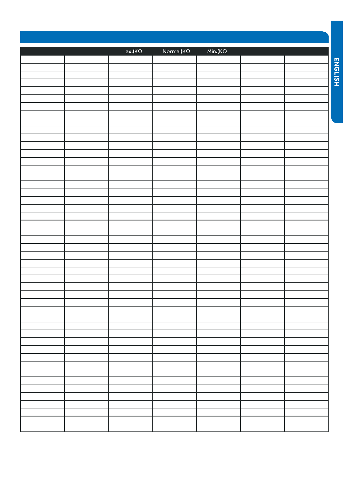
REFERENCE INFORMATION
Room and Coil Sensor Tables
.pmeTF° .pmeT °C M ) ) ) Tolerance (°C)
149 65 2.4591 2.284 2.1195 -2.36 2.21
150.8 66 2.3815 2.2098 2.0486 -2.4 2.25
152.6 67 2.3068 2.1383 1.9803 -2.45 2.29
154.4 68 2.2347 2.0695 1.9147 -2.49 2.34
156.2 69 2.1652 2.0032 1.8516 -2.54 2.38
158 70 2.0983 1.9393 1.7908 -2.59 2.42
159.8 71 2.0337 1.8778 1.7324 -2.63 2.46
161.6 72 1.9714 1.8186 1.6761 -2.68 2.5
163.4 73 1.9113 1.7614 1.6219 -2.73 2.54
165.2 74 1.8533 1.7064 1.5697 -2.78 2.58
167 75 1.7974 1.6533 1.5194 -2.83 2.63
168.8 76 1.7434 1.6021 1.471 -2.88 2.67
170.6 77 1.6913 1.5528 1.4243 -2.92 2.71
172.4 78 1.6409 1.5051 1.3794 -2.97 2.75
174.2 79 1.5923 1.4592 1.336 -3.02 2.8
176 80 1.5454 1.4149 1.2942 -3.07 2.84
177.8 81 1.5 1.3721 1.254 -3.12 2.88
179.6 82 1.4562 1.3308 1.2151 -3.17 2.93
181.4 83 1.4139 1.291 1.1776 -3.22 2.97
183.2 84 1.373 1.2525 1.1415 -3.27 3.01
185 85 1.3335 1.2153 1.1066 -3.32 3.06
186.8 86
●
1.2953 1.1794 1.073 -3.38 3.1
188.6 87 1.2583 1.1448 1.0405 -3.43 3.15
190.4 88
●
1.2226 1.1113 1.0092 -3.48 3.19
192.2 89 1.188 1.0789 0.9789 -3.53 3.24
194 90 1.1546 1.0476 0.9497 -3.58 3.28
195.8 91
●
1.1223 1.0174 0.9215 -3.64 3.33
197.6 92 1.091 0.9882 0.8942 -3.69 3.37
199.4 93 1.0607 0.9599 0.8679 -3.74 3.42
201.2 94 1.0314 0.9326 0.8424 -3.8 3.46
203 95 1.003 0.9061 0.8179 -3.85 3.51
204.8 96 0.9756 0.8806 0.7941 -3.9 3.55
206.6 97 0.949 0.8558 0.7711 -3.96 3.6
208.4 98 0.9232 0.8319 0.7489 -4.01 3.64
210.2 99 0.8983 0.8088 0.7275 -4.07 3.69
212 100
●
0.8741 0.7863 0.7067 -4.12 3.74
213.8 101 0.8507 0.7646 0.6867 -4.18 3.78
215.6 102 0.8281 0.7436 0.6672 -4.23 3.83
217.4 103 0.8061 0.7233 0.6484 -4.29 3.88
219.2 104 0.7848 0.7036 0.6303 -4.34 3.92
221 105 0.7641 0.6845 0.6127 -4.4 3.97
222.8 106 0.7441 0.6661 0.5957 -4.46 4.02
224.6 107 0.7247 0.6482 0.5792 -4.51 4.07
226.4 108 0.7059 0.6308 0.5632 -4.57 4.12
228.2 109 0.6877 0.614 0.5478 -4.63 4.16
230 110 0.67 0.5977 0.5328 -4.69 4.21
231.8 111 0.6528 0.582 0.5183 -4.74 4.26
233.6 112 0.6361 0.5667 0.5043 -4.8 4.31
PAGE 109
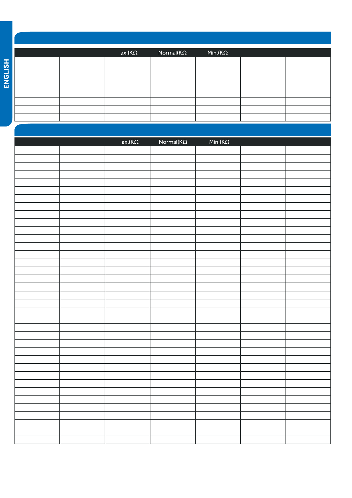
Room and Coil Sensor Tables
Ambient , Defrost and Pipe Sensor Tables
●
.pmeTF° .pmeT °C M ) ) ) Tolerance (°C)
235.4 113 0.62 0.5518 0.4907 -4.86 4.36
237.2 114 0.6043 0.5374 0.4775 -4.92 4.41
239 115 0.5891 0.5235 0.4648 -4.98 4.45
240.8 116 0.5743 0.51 0.4524 -5.04 4.5
242.6 117 0.56 0.4968 0.4404 -5.1 4.55
244.4 118 0.546 0.4841 0.4288 -5.16 4.6
246.2 119 0.5325 0.4717 0.4175 -5.22 4.65
248 120 0.5194 0.4597 0.4066 -5.28 4. 7
.pmeTF° .pmeT °C M ) ) ) Tolerance (°C)
-22 -30 165.2170 147.9497 132.3678 -1.94 1.75
-20 -29 155.5754 139.5600 125.0806 -1.93 1.74
-18 -28 146.5609 131.7022 118.2434 -1.91 1.73
-17 -27 138.1285 124.3392 111.8256 -1.89 1.71
-15 -26 130.2371 117.4366 105.7989 -1.87 1.70
-13 -25 122.8484 110.9627 100.1367 -1.85 1.69
-11 -24 115.9272 104.8882 94.8149 -1.83 1.67
-9 -23 109.4410 99.1858 89.8106 -1.81 1.66
-8 -22 103.3598 93.8305 85.1031 -1.80 1.64
-6 -21 97.6556 88.7989 80.6728 -1.78 1.63
-4 -20 92.3028
●
84.0695 76.5017 -1.76 1.62
-2 -19 87.2775
●
79.6222 72.5729 -1.74 1.60
0 -18 82.5577 75.4384 68.8710 -1.72 1.59
1 -17 78.1230 71.5010 65.3815 -1.70 1.57
3 -16 73.9543 67.7939 62.0907 -1.68 1.55
5 -15 70.0342 64.3023 58.9863 -1.66 1.54
7 -14 66.3463 61.0123 56.0565 -1.64 1.52
9 -13 62.8755 57.9110 53.2905 -1.62 1.51
10 -12 59.6076 54.9866 50.6781 -1.60 1.49
12 -11
●
56.5296 52.2278 48.2099 -1.58 1.47
14 -10 53.6294 49.6244 45.8771 -1.56 1.46
16 -9 50.8956 47.1666 43.6714 -1.54 1.44
18 -8 48.3178 44.8454 41.5851 -1.51 1.42
19 -7 45.8860 42.6525 39.6112 -1.49 1.40
21 -6 43.5912 40.5800 37.7429 -1.47 1.39
23 -5 41.4249 38.6207 35.9739 -1.45 1.37
25 -4 39.3792 36.7676 34.2983 -1.43 1.35
27 -3 37.4465 35.0144 32.7108 -1.41 1.33
28 -2 35.6202 33.3552 31.2062 -1.38 1.31
30 -1 33.8936 31.7844 29.7796 -1.36 1.29
32 0 32.2608
●
30.2968 28.4267 -1.34 1.28
34 1 30.7162 28.8875 27.1431 -1.32 1.26
36 2 29.2545 27.5519 25.9250 -1.29 1.24
37 3 27.8708 26.2858 24.7686 -1.27 1.22
39 4 26.5605 25.0851 23.6704 -1.25 1.20
41 5 25.3193 23.9462 22.6273 -1.23 1.18
43 6 24.1432 22.8656 21.6361 -1.20 1.16
REFERENCE INFORMATION
PAGE 110
REFERENCE INFORMATION
Ambient , Defrost and Pipe Sensor Tables
.pmeTF° .pmeT °C M ) ) ) Tolerance (°C)
45 7 23.0284 21.8398 20.6939 -1.18 1.14
46 8 21.9714 20.8659 19.7982 -1.15 1.12
48 9
●
20.9688 19.9409 18.9463 -1.13 1.09
50 10
●
20.0176 19.0621 18.1358 -1.11 1.07
52 11 19.1149 18.2270 17.3646 -1.08 1.05
54 12 18.2580 17.4331 16.6305 -1.06 1.03
55 13 17.4442 16.6782 15.9315 -1.03 1.01
57 14 16.6711 15.9601 15.2657 -1.01 0.99
59 15 15.9366 15.2770 14.6315 -0.98 0.96
61 16
●
15.2385 14.6268 14.0271 -0.96 0.94
63 17 14.5748 14.0079 13.4510 -0.93 0.92
64 18 13.9436 13.4185 12.9017 -0.91 0.90
66 19 13.3431 12.8572 12.3778 -0.88 0.87
68 20 12.7718 12.3223 11.8780 -0.86 0.85
70 21 12.2280 11.8126 11.4011 -0.83 0.83
72 22 11.7102 11.3267 10.9459 -0.81 0.80
73 23 11.2172 10.8634 10.5114 -0.78 0.78
75 24 10.7475 10.4216 10.0964 -0.75 0.75
77 25 10.3000 10.0000 9.7000 -0.75 0.75
79 26 9.8975 9.5974 9.2980 -0.76 0.76
81 27 9.5129 9.2132 8.9148 -0.80 0.80
82 28 9.1454 8.8465 8.5496 -0.84 0.83
84 29 8.7942 8.4964 8.2013 -0.87 0.86
86 30
●
8.4583 8.1621 7.8691 -0.91 0.90
88 31
●
8.1371 7.8428 7.5522 -0.95 0.93
90 32 7.8299 7.5377 7.2498 -0.98 0.97
91 33 7.5359 7.2461 6.9611 -1.02 1.00
93 34 7.2546 6.9673 6.6854 -1.06 1.04
95 35 6.9852 6.7008 6.4222 -1.10 1.07
97 36 6.7273 6.4459 6.1707 -1.13 1.11
99 37 6.4803 6.2021 5.9304 -1.17 1.14
100 38 6.2437 5.9687 5.7007 -1.21 1.18
102 39 6.0170 5.7454 5.4812 -1.25 1.22
104 40 5.7997 5.5316 5.2712 -1.29 1.25
106 41 5.5914 5.3269 5.0704 -1.33 1.29
108 42 5.3916 5.1308 4.8783 -1.37 1.33
109 43 5.2001 4.9430 4.6944 -1.41 1.36
111 44 5.0163 4.7630 4.5185 -1.45 1.40
113 45 4.8400 4.5905 4.3500 -1.49 1.44
115 46 4.6708 4.4252 4.1887 -1.53 1.47
117 47 4.5083 4.2666 4.0342 -1.57 1.51
118 48 4.3524 4.1145 3.8862 -1.61 1.55
120 49 4.2026 3.9686 3.7443 -1.65 1.59
122 50 4.0588 3.8287 3.6084 -1.70 1.62
124 51 3.9206 3.6943 3.4780 -1.74 1.66
126 52 3.7878 3.5654 3.3531 -1.78 1.70
127 53 3.6601 3.4416 3.2332 -1.82 1.74
129 54 3.5374 3.3227 3.1183 -1.87 1.78
PAGE 111
REFERENCE INFORMATION
Ambient , Defrost and Pipe Sensor Tables
.pmeTF° .pmeT °C M ) ) ) Tolerance (°C)
131 55 3.4195 3.2085 3.0079 -1.91 1.82
133 56 3.3060 3.0989 2.9021 -1.95 1.85
135 57 3.1969
●
2.9935 2.8005 -2.00 1.89
136 58 3.0919
●
2.8922 2.7029 -2.04 1.93
138 59 2.9909 2.7948 2.6092 -2.08 1.97
140 60 2.8936 2.7012 2.5193 -2.13 2.01
142 61 2.8000 2.6112 2.4328 -2.17 2.05
144 62 2.7099 2.5246 2.3498 -2.22 2.09
145 63 2.6232 2.4413 2.2700 -2.26 2.13
147 64 2.5396
●
2.3611 2.1932 -2.31 2.17
149 65 2.4591 2.2840 2.1195 -2.36 2.21
151 66 2.3815 2.2098 2.0486 -2.40 2.25
153 67 2.3068 2.1383 1.9803 -2.45 2.29
154 68 2.2347 2.0695 1.9147 -2.49 2.34
156 69 2.1652 2.0032 1.8516 -2.54 2.38
158 70 2.0983 1.9393 1.7908 -2.59 2.42
160 71 2.0337 1.8778 1.7324 -2.63 2.46
162 72 1.9714 1.8186 1.6761 -2.68 2.50
163 73 1.9113 1.7614 1.6219 -2.73 2.54
165 74 1.8533 1.7064 1.5697 -2.78 2.58
167 75 1.7974 1.6533 1.5194 -2.83 2.63
169 76 1.7434 1.6021 1.4710 -2.88 2.67
171 77 1.6913 1.5528 1.4243 -2.92 2.71
172 78 1.6409
●
1.5051 1.3794 -2.97 2.75
174 79 1.5923
●
1.4592 1.3360 -3.02 2.80
176 80 1.5454 1.4149 1.2942 -3.07 2.84
178 81 1.5000 1.3721 1.2540 -3.12 2.88
180 82 1.4562 1.3308 1.2151 -3.17 2.93
181 83 1.4139 1.2910 1.1776 -3.22 2.97
183 84 1.3730 1.2525 1.1415 -3.27 3.01
185 85 1.3335 1.2153 1.1066 -3.32 3.06
187 86 1.2953 1.1794 1.0730 -3.38 3.10
189 87 1.2583 1.1448 1.0405 -3.43 3.15
190 88 1.2226 1.1113 1.0092 -3.48 3.19
192 89 1.1880 1.0789 0.9789 -3.53 3.24
194 90 1.1546 1.0476 0.9497 -3.58 3.28
196 91 1.1223 1.0174 0.9215 -3.64 3.33
198 92 1.0910 0.9882 0.8942 -3.69 3.37
199 93 1.0607 0.9599 0.8679 -3.74 3.42
201 94 1.0314 0.9326 0.8424 -3.80 3.46
203 95 1.0030 0.9061 0.8179 -3.85 3.51
205 96 0.9756 0.8806 0.7941 -3.90 3.55
207 97 0.9490 0.8558 0.7711 -3.96 3.60
208 98 0.9232 0.8319 0.7489 -4.01 3.64
210 99 0.8983 0.8088 0.7275 -4.07 3.69
212 100 0.8741 0.7863 0.7067 -4.12 3.74
214 101 0.8507 0.7646 0.6867 -4.18 3.78
216 102 0.8281 0.7436 0.6672 -4.23 3.83
(°C)
PAGE 112
Discharge Sensor Tables
●
Ambient , Defrost and Pipe Sensor Tables
.pmeTF° .pmeT °C M ) ) ) Tolerance (°C)
217 103 0.8061 0.7233 0.6484 -4.29 3.88
219 104 0.7848 0.7036 0.6303 -4.34 3.92
221 105 0.7641 0.6845 0.6127 -4.40 3.97
223 106 0.7441 0.6661 0.5957 -4.46 4.02
225 107 0.7247 0.6482 0.5792 -4.51 4.07
226 108 0.7059 0.6308 0.5632 -4.57 4.12
228 109 0.6877 0.6140 0.5478 -4.63 4.16
230 110 0.6700 0.5977 0.5328 -4.69 4.21
232 111 0.6528 0.5820 0.5183 -4.74 4.26
234 112 0.6361 0.5667 0.5043 -4.80 4.31
235 113 0.6200 0.5518 0.4907 -4.86 4.36
237 114 0.6043 0.5374 0.4775 -4.92 4.41
239 115 0.5891 0.5235 0.4648 -4.98 4.45
241 116 0.5743 0.5100 0.4524 -5.04 4.50
243 117 0.5600 0.4968 0.4404 -5.10 4.55
244 118 0.5460 0.4841 0.4288 -5.16 4.60
246 119 0.5325 0.4717 0.4175 -5.22 4.65
248 120 0.5194 0.4597 0.4066 -5.28 4.70
Temp.(°F) Temp.(°C) M )
●
) ) Tolerance
-22 -30
●
14646.0505 12061.7438 9924.4999 -2.96 2.45
-20.2 -29 13654.1707 11267.873 9290.2526 -2.95 2.44
-18.4 -28 12735.8378 10531.3695 8700.6388 -2.93 2.44
-16.6 -27 11885.1336 9847.724 8152.2338 -2.92 2.43
-14.8 -26 11096.6531 9212.8101 7641.8972 -2.91 2.42
-13 -25 10365.4565 8622.8491 7166.7474 -2.9 2.42
-11.2 -24 9687.027 8074.3787 6724.1389 -2.88 2.41
-9.4 -23 9057.2314 7564.2244 6311.6413 -2.87 2.41
-7.6 -22 8472.2852 7089.4741 5927.0206 -2.86 2.4
-5.8 -21 7928.7217 6647.4547 5568.2222 -2.84 2.39
-4 -20 7423.3626 6235.7109 5233.3554 -2.83 2.39
-2.2 -19 6953.293 5851.9864 4920.6791 -2.82 2.38
-0.4 -18 6515.8375 5494.2064 4628.5894 -2.8 2.37
1.4 -17 6108.5393 5160.4621 4355.6078 -2.79 2.37
3.2 -16 5729.1413 4848.9963 4100.3708 -2.77 2.36
5 -15 5375.5683 4558.1906 3861.6201 -2.76 2.35
6.8 -14 5045.9114 4286.5535 3638.1938 -2.75 2.34
8.6 -13 4738.4141 4032.7098 3429.0191 -2.73 2.34
10.4 -12
●
4451.4586 3795.391 3233.1039 -2.72 2.33
12.2 -11 4183.5548 3573.426 3049.5312 -2.7 2.32
14 -10 3933.3289 3365.7336 2877.4527 -2.69 2.31
15.8 -9 3699.5139 3171.3148 2716.0828 -2.67 2.3
17.6 -8 3480.9407 2989.246 2564.6945 -2.66 2.29
19.4 -7
●
3276.5302 2818.6731 2422.6139 -2.64 2.28
21.2 -6 3085.2854 2658.8058 2289.2164 -2.63 2.28
23 -5 2906.2851 2508.9126 2163.923 -2.61 2.27
R176° =
B77°/176° =
REFERENCE INFORMATION
PAGE 113
REFERENCE INFORMATION
Discharge Sensor Tables
Temp.(°F) Temp.(°C) M ) ) ) Tolerance
24.8 -4 2738.6777 2368.3158 2046.1961 -2.6 2.26
26.6 -3 2581.6752 2236.3876 1935.5371 -2.58 2.25
28.4 -2 2434.5487 2112.5459 1831.4826 -2.56 2.24
30.2 -1 2296.623 1996.2509 1733.6024 -2.55 2.23
32 0 2167.273 1887.0018 1641.4966 -2.53 2.22
33.8 1 2045.9191 1784.3336 1554.7931 -2.52 2.21
35.6 2 1932.0242 1687.8144 1473.146 -2.5 2.2
37.4 3 1825.0899 1597.0431 1396.2333 -2.48 2.19
39.2 4 1724.654 1511.6468 1323.7551 -2.47 2.17
41 5 1630.287 1431.2787 1255.4324 -2.45 2.16
42.8 6 1541.5904 1355.6163 1191.0048 -2.43 2.15
44.6 7 1458.1938 1284.3593 1130.2298 -2.41 2.14
46.4 8 1379.7528 1217.2282 1072.8813 -2.4 2.13
48.2 9 1305.9472 1153.9626 1018.7481 -2.38 2.12
50 10 1236.4792 1094.32 967.6334 -2.36 2.11
51.8 11 1171.0715 1038.0743 919.3533 -2.35 2.09
53.6 12 1109.4661 985.0146 873.7359 -2.33 2.08
55.4 13
●
1051.4226 934.944 830.621 -2.31 2.07
57.2 14 996.7169 887.6792 789.8583 -2.29 2.06
59 15 945.1404 843.0486 751.3077 -2.27 2.04
60.8 16 896.4981 800.8922 714.838
●
-2.26 2.03
62.6 17 850.6086 761.0603 680.3265
●
-2.24 2.02
64.4 18 807.3024 723.4134 647.658 -2.22 2
66.2 19 766.4212 687.8205 616.7252 -2.2 1.99
68 20 727.8172 654.1596 587.4271 -2.18 1.98
69.8 21 691.3524 622.3161 559.6694 -2.16 1.96
71.6 22
●
656.8979 592.1831 533.3634 -2.14 1.95
73.4 23 624.3328 563.6604 508.4261 -2.12 1.93
75.2 24 593.5446 536.654 484.7796 -2.1 1.92
77 25 564.4275 511.076 462.351 -2.09 1.9
78.8 26 536.9865 486.9352 441.1516 -2.07 1.89
80.6 27 511.0105 464.05 421.0258 -2.05 1.87
82.4 28 486.4151 442.3499 401.9146
●
-2.03 1.86
84.2 29 463.1208 421.7683 383.7626 -2.01 1.84
86 30 441.0535 402.243 366.5175 -1.99 1.83
87.8 31 420.1431 383.7151 350.1301 -1.97 1.81
89.6 32 400.3242 366.1295 334.5542 -1.95 1.8
91.4 33 381.535 349.4341 319.746 -1.93 1.78
93.2 34 363.7176 333.5801 305.6645 -1.9 1.76
95 35 346.8176 318.5216 292.2709 -1.88 1.75
96.8 36 330.7839 304.2151 279.5286 -1.86 1.73
98.6 37 315.5682 290.6199 267.4031 -1.84 1.71
100.4 38 301.1254 277.6976 255.862 -1.82 1.7
102.2 39 287.4128 265.4119 244.8745 -1.8 1.68
104 40 274.3905 253.7288 234.4118 -1.78 1.66
105.8 41 262.0206 242.6161 224.4465 -1.76 1.64
107.6 42 250.2676 232.0436 214.9529 -1.74 1.63
109.4 43 239.0983 221.9825 205.9065 -1.71 1.61
111.2 44 228.4809 212.406 197.2844 -1.69 1.59
PAGE
Discharge Sensor Tables
Temp.(°F) Temp.(°C) M ) ) ) Tolerance
113 45 218.386 203.2887 189.0648 -1.67 1.57
114.8 46 208.7855 194.6066 181.2273 -1.65 1.55
116.6 47 199.6531 186.3369 173.7524 -1.63 1.54
118.4 48 190.9639 178.4584 166.6217 -1.6 1.52
120.2 49 182.6945 170.9508 159.8181 -1.58 1.5
122 50 174.8228 163.7951 153.3249 -1.56 1.48
123.8 51 167.328 156.9733 147.1268 -1.53 1.46
125.6
●
52 160.1904 150.4683 141.209 -1.51 1.44
127.4 53 153.3914 144.2641 135.5577 -1.49 1.42
129.2 54 146.9136 138.3454 130.1598 -1.47 1.4
131 55 140.7403 132.698 125.0027 -1.44 1.38
132.8 56 134.8559 127.3081 120.0746 -1.42 1.36
134.6 57 129.2457 122.163 115.3645 -1.4 1.34
136.4 58 123.8956 117.2504 110.8618 -1.37 1.32
138.2 59 118.7926 112.5589 106.5564 -1.35 1.3
140 60 113.9241 108.0776 102.4388 -1.32 1.28
141.8 61 109.2784 103.7961 98.5 -1.3 1.26
143.6 62 104.8443 99.7046 94.7315 -1.28 1.23
145.4 63 100.6112 95.7939 91.1253 -1.25 1.21
147.2 64
●
96.5692 92.0553 87.6735 -1.23 1.19
149 65 92.7088 88.4805 84.369 -1.2 1.17
150.8 66 89.0211 85.0614 81.2048 -1.18 1.15
152.6 67 85.4976 81.7908 78.1744 -1.15 1.12
154.4 68 82.1303 78.6615 75.2715 -1.13 1.1
156.2 69 78.9116 75.6668 72.4902 -1.1 1.08
158 70 75.8343 72.8004 69.8249 -1.08 1.06
159.8 71 72.8916 70.0561 67.2703 -1.05 1.03
161.6 72 70.077 67.4283 64.8213 -1.03 1.01
163.4 73 67.3844 64.9115 62.4731 -1 0.99
165.2 74 64.808 62.5006 60.2211 -0.98 0.96
167 75 62.3423 60.1906 58.0609 -0.95 0.94
168.8 76 59.9821 57.977 55.9885 -0.92 0.92
170.6 77 57.7223 55.8552 53.9998 -0.9 0.89
172.4 78 55.5583 53.821 52.0912 -0.87 0.87
174.2 79 53.4856 51.8706 50.2591 -0.85 0.84
176 80 51.5 50 48.5 -0.85 0.84
177.8 81 49.7063 48.2057 46.7083 -0.85 0.85
179.6 82 47.9835 46.4842 44.9911 -0.89 0.89
181.4 83 46.3286 44.8323 43.3452 -0.93 0.92
183.2 84
●
44.7385 43.2468 41.7672 -0.96 0.95
185 85 43.2105 41.7248 40.254 -1 0.99
186.8 86 41.7386 40.2604 38.7996 -1.03 1.02
188.6 87 40.3241 38.8545 37.4048 -1.07 1.06
190.4 88
●
38.9643 37.5045 36.0668 -1.11 1.09
192.2 89 37.6569
●
36.2078 34.7831 -1.14 1.13
194 90 36.3996 34.9622 33.5513 -1.18 1.16
195.8 91 35.1903 33.7653 32.3689 -1.22 1.19
197.6 92 34.0269 32.6151 31.2338 -1.26 1.23
199.4 93 32.9075 31.5096 30.1438 -1.3 1.27
REFERENCE INFORMATION
PAGE
Discharge Sensor Tables
Temp.(°F) Temp.(°C) M ) ) ) Tolerance
201.2 94 31.8302 30.4467 29.097 -1.33 1.3
203 95 30.7933 29.4246 28.0915 -1.37 1.34
204.8 96 29.795 28.4417 27.1254 -1.41 1.37
206.6 97 28.8337 27.4961 26.197 -1.45 1.41
208.4 98 27.9078
●
26.5864 25.3048 -1.49 1.44
210.2 99 27.016 25.711 24.447 -1.53 1.48
212 100 26.1569 24.8685 23.6222 -1.57 1.52
213.8 101 25.329 24.0574 22.8291 -1.61 1.55
215.6 102 24.5311 23.2765 22.0662 -1.65 1.59
217.4 103 23.762 22.5245 21.3323 -1.69 1.63
219.2 104 23.0205 21.8002 20.6261 -1.73 1.66
221 105 22.3055 21.1025 19.9465 -1.77 1.7
222.8 106 21.6159
●
20.4303 19.2924 -1.81 1.74
224.6 107 20.9508 19.7825 18.6626 -1.85 1.77
226.4 108 20.3091 19.1582 18.0563 -1.89 1.81
228.2 109 19.6899
●
18.5564 17.4723 -1.93 1.85
230 110 19.0924 17.9761 16.9098 -1.98 1.89
231.8 111 18.5157
●
17.4166 16.368 -2.02 1.93
233.6 112 17.959 16.8769 15.8458 -2.06 1.96
235.4 113 17.4214 16.3564 15.3427 -2.1 2
237.2 114 16.9023 15.8542 14.8577 -2.15 2.04
239 115 16.401 15.3696 14.3902 -2.19 2.08
240.8 116 15.9167 14.902 13.9394 -2.23 2.12
242.6 117 15.4489 14.4506 13.5047 -2.27 2.16
244.4 118 14.9968 14.0149 13.0855 -2.32 2.19
246.2 119 14.5599 13.5942 12.6811 -2.36 2.23
248 120 14.1376 13.1879 12.2909 -2.41 2.27
249.8 121 13.7294 12.7955 11.9144 -2.45 2.31
251.6 122 13.3347 12.4165 11.551 -2.5 2.35
253.4 123 12.9531 12.0503 11.2003 -2.54 2.39
255.2 124 12.584 11.6965 10.8617 -2.58 2.43
257 125 12.227 11.3545 10.5348 -2.63 2.47
258.8 126 11.8817 11.024 10.2191 -2.68 2.51
260.6 127 11.5475 10.7046 9.9142 -2.72 2.55
262.4 128 11.2242 10.3957 9.6197 -2.77 2.59
264.2 129 10.9112 10.097 9.3352 -2.81 2.63
266 130 10.6084 9.8082 9.0602 -2.86 2.67
267.8 131 10.3151 9.5288 8.7945 -2.91 2.71
269.6 132 10.0312 9.2586 8.5378 -2.95 2.75
271.4 133 9.7563 8.9971 8.2895 -3 2.8
273.2 134 9.4901
●
8.7441 8.0495 -3.05 2.84
275 135 9.2322 8.4993 7.8175 -3.09 2.88
276.8 136 8.9824 8.2623 7.5931 -3.14 2.92
278.6 137 8.7404 8.0329 7.376 -3.19 2.96
280.4 138 8.5059 7.8108 7.166 -3.24 3
282.2 139 8.2787 7.5958 6.9629 -3.29 3.04
284 140 8.0584 7.3875 6.7664 -3.33 3.09
REFERENCE INFORMATION
PAGE

www.geappliances.com
GE Appliances, A Haier Company
Appliance Park, Louisville, KY 40225
©2021 GE Appliances, A Haier Company
Revision Date: March 2021