Loading ...
Loading ...
Loading ...
7
INSTALLATION INSTRUCTIONS
Prepare Location
■ It is recommended that the vent system be installed before the
hood is installed.
■ Before making cutouts, make sure there is proper clearance
within the ceiling for exhaust vent.
■ Hood is to be installed 30" (76.2 cm) minimum for electric
cooking surfaces, 30" (76.2 cm) minimum for gas cooking
surfaces, to a suggested maximum of 36" (91.4 cm) above the
cooking surface.
■ Check your ceiling height and the hood height maximum before
you select your hood.
1. Disconnect power.
2. Determine which venting method to use: roof, wall, or
non-vented.
3. Select a at surface for assembling the hood. Place covering
over that surface.
WARNING
Excessive Weight Hazard
Use two or more people to move and install hood.
Failure to do so can result in back or other injury.
4. Using 2 or more people, lift hood onto covered surface.
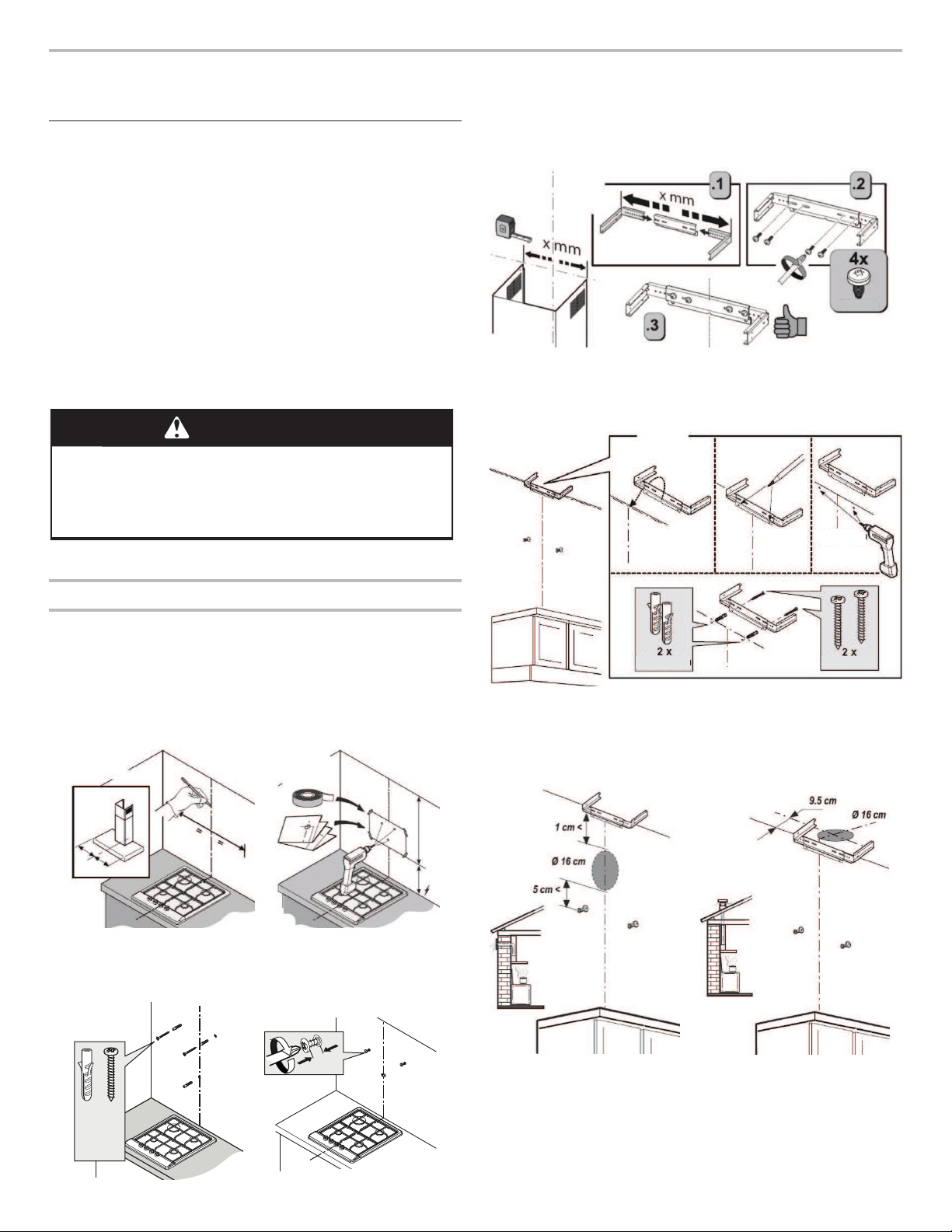
Hood Mounting Screws Installation
1. Establish and mark the center line on the wall where the hood
will be installed, as indicated in gure.
2. Tape the template sheet so the lower edge of the sheet
representing the bottom of the hood is at a mounting height
between a minimum of 30" (76.2 cm) for an electric cooking
surface, a minimum of 30" (76.2 cm) for a gas cooking
surface, and a suggested maximum of 36" (91.4 cm) for both
gas and electric cooking surfaces. Drill 3 holes as shown in
gure.
4 x Ø8 mm
3. Install three Ø8 x 40 mm dowels. Install two Ø5 x 45 mm
screws as shown in gure.
4. Make sure the screw has at least 10 mm distance from the
wall when it is screwed for hood mounting as shown in gure.
10 mm
3x
Ø8x40 mm
2x
Ø5x45 mm
5. Take the chimney xing bracket, adjust the bracket with the
width of the pipe and couple it with 4 screws Ø4x8 mm as
shown in gure, steps 1-2-3-4.
Ø4x8 mm
6. Position the bracket: The center line drawn will facilitate
the correct positioning of the bracket.Mark the 2 holes for
wall mounting, drill the holes Ø8 mm and install 2 plugs
Ø8 x45 mm and nally x the bracket with the two screws
Ø5x45 mm, as shown in gure.
2 x Ø8 mm
Ø8 x 40 mm Ø5 x 45 mm
7. Prearrange the air duct outlet hole, only in the Exhaust
version.
8. The diameter of the air outlet hole in the wall must be
Ø160 mm, taking into account the measurements indicated
in gure. Make sure the hole does not coincide with the
electrical system.
Loading ...
Loading ...
Loading ...