
7.Insert Arm Assembly into the front of the mounted Base Frame (Figure 3).
8.Swing Arm Assembly to the side and mount Bracket (T) to front of Base Frame using (2) Base Frame Screws (M) (Figure 4).
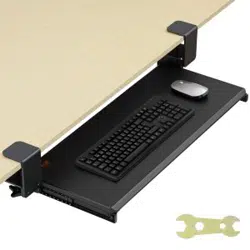
9.The Wrist Rest (E) can be mounted at the front of the platform by removing the backing from the bottom and pressing it firmly into position.
Mouse System Attachment and
Mouse Storage
The Mouse System may be mounted to the right or left side of
the Keyboard Manager Platform (Figure 5). With a Phillips
Screwdriver and a Crescent Wrench secure the Mouse Tray with
(1) Mouse Tray Screw (P), (1) Mouse Spacer (Q), (1) Large
Washer (R) and (1) Lock Nut (S) as illustrated in (Figure 6).
If the Mouse System is being mounted to the right side of the
platform, make sure that the hole in the mouse tray is facing
left with the rounded end of the tray at the front. If it is being
mounted to the left side, make sure that the hole in the mouse
tray is facing right with the rounded end of the tray at the
front, see (Figure 7).
The Mouse Wrist Rest (H) should be placed at the rounded
front end of the tray, and can be mounted by removing the
backing from the bottom of the rest and pressing it firmly into
position. The Mouse Pad (I) should be placed at the rear of the
unit (Figure
9 & 10)
.
NOTE: The Mouse System should be installed after
installation of the Keyboard Manager Arm.
Figure 7
To mount the mouse system on the left side, remove the small bracket on G and assemble it on the opposite side.
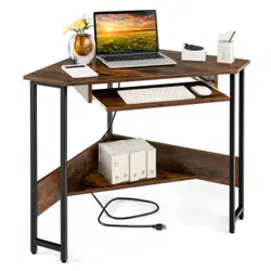
Tools Required:
• Drill
• 1/16" Drill Bit
• Phillips Screwdriver
• Crescent Wrench
CAUTIONS:
Protect your eyes... wear safety goggles
when installing. This unit is not meant to
be sat upon. Do not lubricate Base Frame.
Parts List for Installation:
1. Mounting Template (A) 6. Hardware Pack Includes:
(J) M3.5 x 21mm Rubber Stop Screw (1)
(K) M4 x 8mm Platform Screws (4)
(L) Rubber Stop (1)
(M) M4 x 14mm Base Frame Screws (8)
(N) M5 Lock Washers (4)
(O) M4 Cap Nuts (4)
(P) M6 x 35mm Mouse Tray Screw (1)
(Q) M6 Mouse Spacer (1)
(R) M6 Larger Washer (1)
(S) M6 Lock Nut (1)
(T) Bracket (1)
A
2. Base Frame (B)
B
3. Arm Assembly (C) 4. Keyboard Manager Platform (D), Wrist
Rest (E), Keyboard Pad (F)
D
5. Mouse System [Includes: Mouse Tray
(G), Mouse Wrist Rest (H), Mouse
Pad (I)]
G
H
I
C
O
E
F
K
P
N
S
M
Q
R
T
J
L
80313
Fully Adjustable Keyboard Manager
Support clavier totalement réglable
Soporte de teclado completamente ajustable
Vollverstellbarer Tastaturmanager
Supporto per tastiera totalmente regolabile
Volledig verstelbare keyboardmanager
Fullt justerbart tangentbordssystem
W pe∏ni regulowana szuflada na klawiatur´
Полностью регулируемый менеджер клавиатуры
Instructions for Use
This Articulating Keyboard Manager features height, tilt and
rotation adjustments. To change the height and tilt angle of the
platform, simply turn the knob under the platform counter-
clock-wise and adjust the platform position. To lock the platform
in position, turn the knob clock-wise to secure the platform
position (Figure 12).
The assembled unit rotates 360° at the base frame. The
rotation can be adjusted in the user or stored position. If you
are using the Keyboard Manager, you can use this rotation
feature to fine-tune the platform position. The Keyboard
Manager can be rotated in the stored position to further move
the platform out of the way.
Installation Instructions
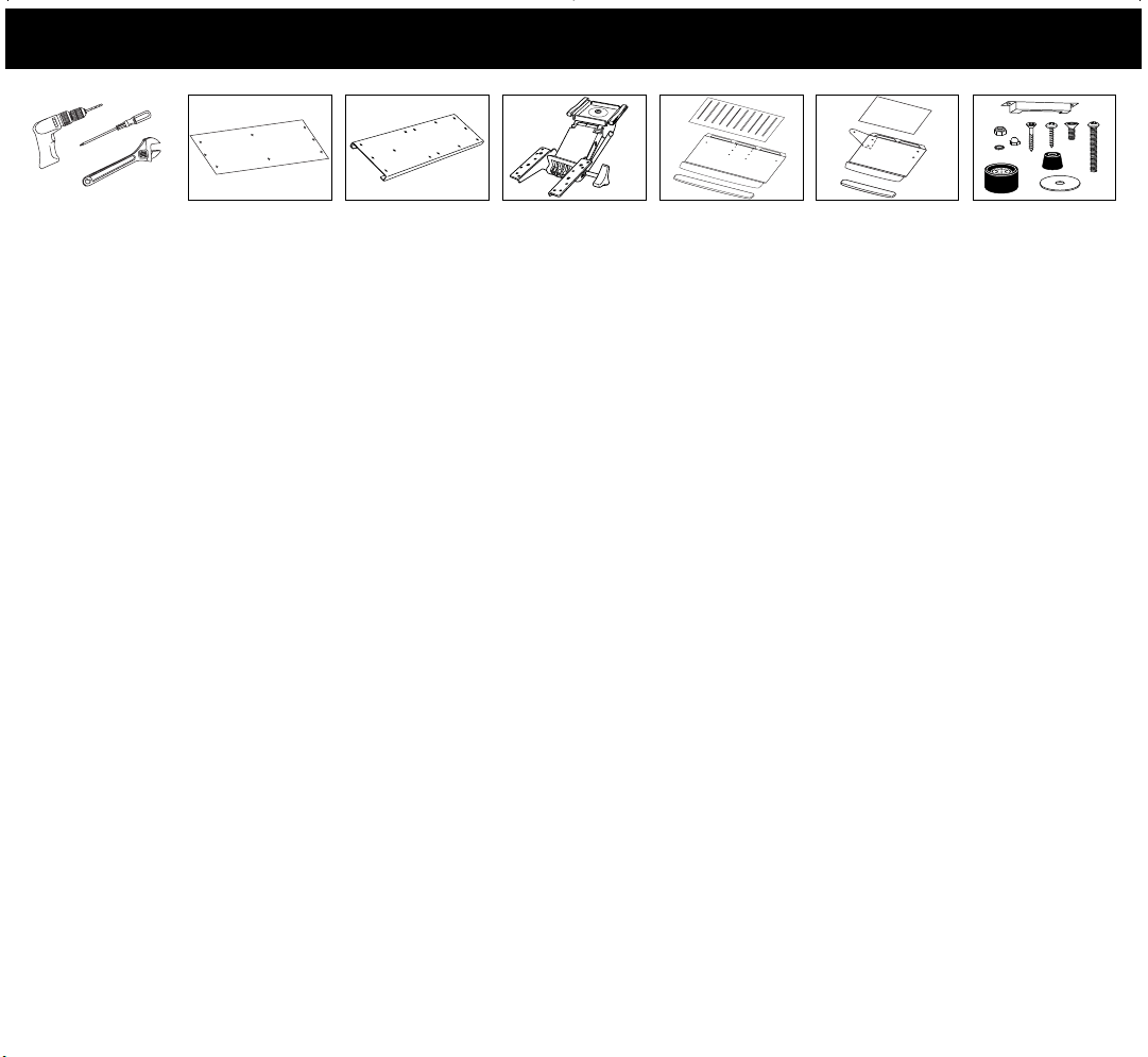
1.Tape Template (A) to the underside of the work surface.
(Note: Be sure to align dotted line with the front edge
of work surface).
2.Drill 1/16" Dia. starter holes where indicated on the template (7)
(Note: Be careful not to drill thru the top of your desk).
3.Remove template.
4.With a Phillips screwdriver, attach the Base Frame (B) to the
underside of the work surface using (6) Base Frame Screws
(M) (Figure 1).
5.Mount Rubber Stop (L) at the back of Base Frame and secure
with Rubber Stop Screw (J) (Figure 1).
Figure 1
Figure 3
Figure 4
6.With Phillips Screwdriver and Crescent Wrench, attach the
Keyboard Manager Platform (D) to the Arm Assembly (C)
with (4) Platform Screws (K), (4) Lock Washers (N) and (4)
Cap Nuts (O) (Figure 2).
Figure 6
Figure 2
The Mouse System can be stored under the Keyboard Manager Platform when not in use (Figure 11). With the Mouse Tray in the up or user
position, gently pull the Mouse Tray in toward the Keyboard Manager Platform. To move the Mouse Tray from the stored position to the user
position, push the Mouse Tray out and away from the platform (Figure 11).
Figure 12
Figure 5
Figure 11
Figure 8
1789 Norwood Avenue Itasc a, Illinois 60143-1095 630-893-1600 http://www.fellowes.com
Australia Benelux Canada France Germany Italy Japan Korea Poland Singapore United Kingdom
© 2004 Fellowes, Inc. Part No. 861920
To assemble the keyboard pad (F), wrist rests E and H, and the mouse pad (I), remove the backing and press firmly into position.
G
S
R
Q
P
F
I
H
E
Figure 9 Figure 10
80313_8_31.qxd 8/31/04 11.13 AM Page 1
A
B
C
F
DE
I
G
H
S
O
N
Q
L
R
J
M
T
K
P
Outils né cessaires
• Perceuse
• Mèche de 1/16 po
• Tournevis cruciforme
• Clé à molette en forme de croissant
MISES EN GARDE
Proté gez vos yeux… portez des lunettes de sé curité durant l’installatio n.
Ne pas s’asseoir sur ce support. Ne pas lubrifier la plate-forme.
Liste des pièces né cessaires à l’installation
1. Gabarit de montage (
A
)
2. Plate-forme (
B
)
3. Bras support (
C
)
4. Plate-forme du support clavier (
D
), Repose-poignets (
E
), Tapis clavier (
F
)
5. Le systè me souris pivotant : le porte-souris (
G
), le repose-poignets pour
souris (
H
), le tap is de souris (
I
)
6. Visserie :
(
J
) Vis d'arrê t en caoutchouc M3,5 x 21 mm (1)
(
K
) Vis de plate-forme M4 x 8 m m (
4
)
(
L
) Buté e en caoutchouc (1)
(M) Vis de châ ssis M4 x 14 mm (8)
(
N
) Rondelles fr ein M5 (
4
)
(
O
) Écro us borgnes M4 (
4
)
(
P
) Vis de porte-souris M6 X 35 mm (
1
)
(
Q
) Entretoise de souris M6 (
1
)
(
R
) Rondelle plus grosse M6 (
1
)
(
S
) Éc rou frein M6 (
1
)
(T) Fixation (1)
Directives d’installation
1. Avec du ruban adhés if, collez le gabarit de montage (
A
) au dessous de la
table de travail. (
Remarque : Assurez-vous de bien aligner le pointillé
avec le bord avant de la table de travail.
)
2. Percez (7) trous de 1,6 mm de diamè tre aux endro its indiqués sur le
gabarit de m ontage. (
Remarque : Prenez garde de ne pas transpercer
la surface de la table de travail !
)
3. Enlevez le gabarit.
4. A l'aide d'un tou rnevis Phillips, fixer le châ ssis (B) à la partie inférieure
de la surface de t ravail à l'aide des (6) vis de châ ssis (
M
) (
Figure 1
).
5. Monter la buté e en caoutchouc ( L) à l'arrière du châssis et fixer la vis
d'arrê t en caoutchouc (
J
) (
Figure 1
).
6. À l’aide d’un tournevis cruciforme et d’une clé à molette en forme de
croissant, fixez la p late-forme du support clavier (
D
) au bras s upport (
C
)
avec les 4 vis de plate-forme (
K
), les 4 rondelles frein (
N
) et les 4
écrous b orgnes (
O
) (
Figure 2
).
7. Insérez le bras de support sur le dessus de la plate-forme. (
Figure 3
)
8. Pivoter l'ensemble sur un cô té et mo nter la fixation (T) à l'avant du
châ ssis à l'aide de (2) vis de c hâssis (M) (
Figure
4).
9. Le repose-poignets en gel (
E
) peut ê tre monté sur le bord avant de la
plate-forme en enlev ant le papier de protection du re pose-poignets et en
pressant celui-ci fermement.
Accessoire de système souris et rangement de la
souris
Le systè me souris peut être monté à droite ou à gauche de la plate-forme
du support clav ier (
Figure 5
). Avec un tournevis cruciforme et une clé à
molette en for me de croissant, bloquez le porte-souris avec (1) vis de
porte-souris (
P
), (1) entretoise de sour is (
Q
), (1) grande rondelle (
R
) et
(1) é crou frein (
S
) comme illustré (
Figure 6
). Si le s ystème souris est
monté sur le côté droit de la plate-forme, assurez-vous que le trou du
porte-souris est orie nté v ers la gauche avec le cô té ar rondi du porte-souris
sur le d evant. Si le système souris est monté sur le cô té gau che de la plate-
forme, assurez-vous que le trou du porte-souris est orienté vers la droite
avec le côté arrondi du porte-souris sur le devant (
Figure 7
).
Le repose-poignets pour souris (
H
) doit ê tre placé sur le cô té avant arrondi
du porte-souris et p eut ê tre monté en retirant la protection sous le repose-
poignets et en appuyant fermement. Le tapis de souris (
I
) doit ê tre placé à
l’arriè re de l’unité (
Figures 9 et 10
).
REMARQUE : Le système souris doit être installé après installation du
bras de support clavier.
Pour monter l e système à gauche, enlevez le pe tit support sur
G
et
assemblez-le-au coté opposé.
Pour assembler le t apis clavier (
F
), les r epose-poignets (
E, H
), et le tapis
souris (
I
), retir er le papier de protection et presse r les é léments fermement
en position.
Le systè me souris pivotant peut ê tre rangé sous la pla te-forme du support
clavier aprè s usage (
Figure 11
). Lorsque le por te-souris est en position
haute (position util isation), tirez-le doucement vers le bas et vers la plate-
forme du sup port clavier. Pour déplacer le porte-souris depuis la position
rangement jusqu’à la position utilisation, poussez le porte-souris vers le
haut en l’éloignant de la plate-forme (
Figure 11
).
Mode d’emploi
Ce support clavier articulé présente des rég lages de hauteur, inclinaison et
orientation. Pour changer la hauteur et l’angle d’ inclinaison de la plate-
forme, il suff it de tourner le bouton s ous la plate-forme dans le sens
antihoraire et de ré gler la position de la p late-forme. Pour bloquer la plate-
forme en posi tion, tournez le bouton dans le sens horaire pour bloquer la
position de la plate-forme comme illustré (
Figure 12
).
Une fois assemblé , le support clavier pivote de 360° sur sa base. La
rotation peut ê tre ré glé e en position utilisation ou en position rangement.
En position uti lisation, cette caractéri stique vous permet de ré gler avec
pré cision la position de la plate-forme. En positi on rangement, la mê me
caracté ristique vous permet de dissimuler la plate-forme davanta ge.
Herramientas necesarias
• Taladro
• Broca de 1/16"
• Destornillador Phillips
• Llave de tuercas en forma de media luna
MEDIDAS DE PRECAUCIÓ N
Proté jase los ojos; p óngase lentes protectores al efectuar la instalación. Esta
unidad no es p ara sentarse en ella. No lubr ique la base.
Lista de piezas para la instalación
1. Plantilla de montaje (
A
)
2. Base (
B
)
3. Conjunto del brazo (
C
)
4. Plataforma del soporte de te clado (
D
), Reposamuñ ecas (
E
), Alfombrilla
para t eclado (
F
)
5. Sistema giratorio del rató n: bandeja del rató n (
G
), reposamuñ ecas para
ratón (
H
) y alf ombrilla para rató n (
I
)
6. Piezas de montaje:
(
J
) Tornillos M3,5 x 21 mm para tope de caucho (1)
(
K
) Tornillos M4 x 8 mm para la plat aforma (4)
(
L
) Topes de caucho (1)
(
M
) Tornillos M4 x 14 mm para el escritorio (8)
(
N
) Rondanas fijadoras M5 (4)
(
O
) Tuercas de capuchón M4 (4)
(
P
) Tornillo M6 X 35 mm pa ra la bandeja del r atón (1)
(
Q
) Espaciador M6 para el rató n (1)
(
R
) Rondana grande M6 (1)
(
S
) Tuerca fijadora M6 (1)
(T) Mé nsula (1)
Instrucciones de instalació n
1. Fije con cinta adhesiva la pla ntilla (
A
) a la parte inferior de la s uperficie
de trabajo. (
Nota: Alinee el punteado con el borde delantero de la
superficie de trabajo
).
2. Perfore (7) orificios guía de 1,6 mm de diá metro donde se indica en la
plantilla de m ontaje (
Nota: ¡No perfore de un lado a otro el escritorio!
)
3. Retire la plantilla.
4. Con un destornillador Phillips, adose el armazó n de base (B) a la parte
inferior de la s uperficie de trabajo mediante (6) t ornillos del armazó n de
base (
M
) (
Figura 1
).
5. Monte el tope de caucho (L) en la parte posterior del armazó n de base y
asegú relo con el tornillo para el tope de caucho (J) (Figura 1).
6. Con el destornillador Phillips y la llave de tuercas en forma de media
luna, una la p lataforma del soporte de teclado (
D
) al conjunto del brazo
(
C
) con (4) tornillos para la plataforma (
K
), (4) rondana s fijadoras (
N
) y
(4) tuercas de capuchón (
O
) (
Figura 2
).
7. Inserte el conjunto del brazo e n la parte frontal de l a base ya montada
(
Figura 3
).
8. Balancee el armazón del brazo a un lado y monte la ménsula (T) en el
armazón de base delantera mediante (2) tornillos del armazón de base (M)
(Figura 4).
9. El reposamuñ ecas de g el (
E
) se monta en la parte frontal de la
plataforma; para el lo, retire el papel protector d e la parte inferior del
gel, coló quelo en su posició n y oprímala firmemente.
Accesorio del sistema del ratón y almacenamiento
del rató n
El sistema del ratón puede montarse en el lado derecho o izquierdo de la
plataforma del sopor te de teclado (
Figura 5
). Con un destornillador Phillips
y una llave de tuercas de media luna asegure la bandeja del ratón con (1)
tornillo (
P
), (1) espaciador para ratón (
Q
), (1) r ondana grande (
R
) y (1)
tuerca fijadora (
S
) (
Figura 6
). Si el sistema d el rató n va a montarse en el
lado derecho de la plataforma, asegú rese de que el or ificio de la bandeja
del rató n esté orientado hacia l a izquierda con el extremo redondeado de
la bandeja hac ia adelante. Si el sistema del ratón va a montarse en el la do
izquierdo de la p lataforma, asegúr ese de que el orificio de la bandeja de l
ratón esté orientado hacia la derecha con el extremo redondeado de la
bandeja hacia adelante (
Figura 7
).
El reposamuñ ecas para el ratón (
H
) debe colocarse en el extremo frontal
redondeado de la bandeja, y se monta retirando el papel pr otector de la
parte inferior del re posamuñeca s y oprimiendo f irmemente el
reposamuñeca s en su lugar. La alfombrilla para el ratón (
I)
debe colocarse
en la parte posterior de la unidad
(Figuras 9 y 10)
.
NOTA: El sistema del ratón debe instalarse después de la instalación del
brazo del soporte de teclado.
Para armar el sistema de ratón a la izquierda, quite el pequeñ o soporte
desde
G
y ármelo e n el lado opuesto.
Para armar la alfombrilla para teclado (
F
), los reposamuñ ecas (
E, H
), y la
alfombrilla para rató n (
I
), retir e el papel protector y o prima los elementos
firmemente en posición.
El sistema giratorio del rató n puede almacenarse bajo la plataforma del
soporte del teclado cuando no esté usándose (
Figura 11
). Con la bandeja
del rató n en la posició n superior o de uso, suavemente bá jela hacia la
plataforma del sopor te del teclado. Para mover l a bandeja del rató n de la
posición de almacenamiento a la posición de uso, empú jela hacia arriba,
alejá ndola de l a plataforma (
Figura 11
).
Instrucciones de empleo
Este soporte articulado de teclado incorpora ajustes de altura, inclinació n y
rotación. Para ajustar la altura y el á ngulo de in clinación de la plataforma,
simplemente gire hacia la izquierda la peri lla situada bajo la plataforma y
ajuste la posic ión de la plataforma. Para fij ar la plataforma en una
posición, gire la perilla hacia la derecha para fija r la posició n de la
plataforma (
Figura 12
).
La unidad ya ensamb lada gira 360° en la base. El giro puede aju starse en
la posició n de uso o de almacenamiento. Si está usando el soporte del
teclado, puede usar esta característica de giro para ajustar con precisió n la
posición de la plataforma. El soporte del te clado puede girarse en la
posición de almacenamiento para alejarla aú n más.
Erforderliches Werkzeug
• Bohrmaschine
• 1/16" Bohreinsatz
• Kreuzschlitzschraubenzieher
• Rollgabelschlü ssel
VORSICHTSHINWEISE
Schü tzen Sie Ihre Augen … tragen Sie beim Zusammenbau eine
Schutzbrille. Diese Einheit ist nicht als S itzfläc he vorgesehen. Den
Grundrahmen nicht schmieren.
Teileliste fü r den Zusammenbau
1. Montageschablone (
A
)
2. Grundrahmen (
B
)
3. Armgruppe (
C
)
4. Tastaturmanager-Plattform (
D
), Handgelenkauflage (
E)
,
Tastaturunterlage (
F
)
5. Drehbares Maussystem: Mausfach (
G
), Maus-Handgelenkauflage (
H
),
Maus-Pad (
I
)
6. Montagepackung:
(
J
) M3,5 x 21 mm Gummianschlagschraube (1)
(
K
) M4 x 8 mm Plattformschrauben (4)
(
L
) Gummistopfen (1)
(
M
) M4 x 14 mm Grundrahmenschrauben (8)
(
N
) M5 Sicherungsscheiben (4)
(
O
) M4 Hutmuttern (4)
(
P
) M6 X 3 5 mm Mausfachschraube (1)
(
Q
) M6 Maus-Abstandhalter (1)
(
R
) M6 grö ßerer Unterlegscheibe (1)
(
S
) M6 Geg enmutter (1)
(T) Halterung (1)
Montageanleitung
1. Die Schablone (
A
) an der Untersei te der Arbeitsflä che festkleben
(
Hinweis: Die punktierte Linie mus s mit der Vorderkante der
Arbeitsfläche verlaufen.
)
2. An den markierten Stellen auf der Montageschablone (7) Ansatzlö cher
mit einem Durchmesser vo n 1,6 mm bohren (
Hinweis: Nicht durch die
Schreibtischplatte hindurchbohren!
)
3. Die Schablone entfernen.
4. Den Grundrahmen (B) mit einem Kreuzschraubenzieher und de n (6)
Grundrahmenschrauben (M) an der Un terseite der Arbeitsflä che
befestigen (Abbildung 1).
5. Die Gummistopfen (L) an der Hinterseite des Grundrahmens anbringen
und mi t den Gummianschlagschrauben (J) befestigen (Abbildung 1).
6. Die Tastaturmanager-Plattform (
D
) mit einem Kreuzschli tzschrauben-
zieher und einem Roll gabelschlü ssel sowie mit (4) Plattformschrauben
(
K
), (4) Sic herungsscheiben (
N
) und (4) Hutmut tern (
O
) an der
Armgruppe (
C
) befestigen (
Abbildung 2
).
7. Die Armgruppe vorne in den montie rten Grundrahmen stecken
(
Abbildung 3
).
8. Armeinheit zur Seite schwenken und die Halterung (T) mit (2)
Grundrahmenschrauben (M) an der Vorderseite des Grundrahmens (2)
anbringen (Abbildung 4).
9. Die Gel-Handgelenkauflage (
E
) kann durch A bziehen der Schutzschicht
von der Unterseite des Gel-Teils und Andrü cken vorne an der Plattform
befestigt werden.
Befestigung des Maussystems und
Mausaufbewahrung
Das Maussystem kann auf der rechten oder linken Seite der
Tastaturmanager-Plattform angebracht werden (
Abbildung 5
). Das Mausfach
mit einem Kreuzschlitzschraubenzieher und einem Rollgabelschlüsse l und
unter Verwendung einer (1) Mausfachschraube (
P
), eines (1)
Mausabstandhalters (
Q
), einer (1) größeren Unterlegscheibe (
R
) und einer
(1) Gegenmutter (
S
) gemäß der Darstellung in (
Abbildung 6
) befestigen.
Wenn das Maussystem auf der rechten Seite der Plattform angebracht wird,
ist sicherzustellen, dass das Loch im Mausfach nach links und das
abgerundete Ende des Faches nach vorne zeigt. Bei einer Montage auf der
linken Seite ist darauf zu achten, dass das Loch im Mausfach nach rechts
und das abgerundete Ende des Faches nach vorne zeigt (
Abbildung 7
).
Die Maus-Handgelenkauflage (
H
) sollte an der abgerundeten Vorderseite
des Faches befestigt werde n; dazu wird die Schutzschicht von der Unterseite
der Handgelenkauflage abgezogen un d fest angedrü ckt.
Das Maus-Pad (
I
) sollte hinten an der Baugruppe platziert werden
(Abbildung 9 und 10)
.
HINWEIS: Das Maussystem sollte erst nach der Montage des
Tastaturmanager-Arms installiert werden.
Um das Maussystem auf die link e Seite zu befestigen, entfernen Sie das
kleine Stü tzteil von
G
und auf die Gegenseite mon tieren.
Zur Installation der Tastaturunterlage (
F
), der Handge lenkauflagen (
E, H
),
und des Mauspads (
I
), entfernen Sie die S chutzschicht und die Element e fest
in ihre Position d rück en.
Wenn das drehbare Maussystem nicht in Gebrauch ist, k ann es unter der
Tastaturmanager-Plattform verstaut werden (
Abbildung 11
). Das Mausfach
aus der angehobenen bzw. Benutz erposition behutsam nach unten und in
Richtung auf die Tastaturmanager-Plattform ziehen. Um das Mausfach von
der Ruheposition in d ie Benutzerposition zu versetzen, wird e s nach oben
und von der Pla ttform weggedrü ckt (
Abbildung 11
).
Gebrauchsanleitung
Höhe, Ne igungswinkel und Drehung dieses Gelenktasta turschublades lassen
sich verstellen. Zum Verstellen d er Höhe und des Neigungswinkels der
Plattform einfach den Knopf unter der Plattform nach l inks drehen und
die Position der Plattfo rm einstellen. Zum Feststellen und Sichern der
Plattformposition den Knopf nac h rechts drehen, wie in (
Abbildung 12
)
dargestellt.
Die zusammengebaute Einheit lä sst sich am Grundrahmen um 360°
drehen. Diese Drehung kann s owohl in der Benut zer- als auch in der
Ruheposition anders eingestellt werden. Wenn der Tastaturmanager in
Gebrauch ist, ist mit Hilfe d ieser Drehfunktion eine Feinabstimmung der
Plattformposition mö glich. In der R uheposition kann der Tastaturmanager
weggedreht werden, damit die P lattform nicht im Wege ist.
Benodigde gereedschappen
• Boormachine
• 1/16" boor
• Kruiskop schroevendraaier
• Steeksleutel
LET OP
Bescherm uw ogen. Draag hier toe een veiligheidsbril tijdens het installeren.
Dit toestel is geen zitmeubel! H et basisframe mag niet worden gesmeerd.
Onderdelenlijst voor installatie
1. Montagesjabloon (
A
)
2. Basisframe (
B
)
3. Armconstructie (
C
)
4. Platform voor keyboardmanager (
D
), Polssteun (
E
), Toetsenbord
onderlegger (
F
)
5. Draaibaar muissysteem: muisplateau (
G
), Polssteun voor muis (
H
),
muismat (
I
)
6. Bevestigingsmateriaal:
(
J
) M3,5 x 21 mm rubberstop schroef (1)
(
K
) M4 x 8 mm plateauschroeven (4)
(
L
) Rubberstop (1)
(
M
) M4 x 14 mm basisframe schroeven (8)
(
N
) M5 borgringen (4)
(
O
) M4 afdekmoeren (4)
(
P
) M6 X 35 mm muisladeschroef (1)
(
Q
) M6 muisafstandsstuk (1)
(
R
) M6 grotere sl uitring (1)
(
S
) M6 v ergrendelingsmoer (1)
(T) Console (1)
Instructies voor het installeren
1. Bevestig het montagesjabloon (
A
) op de onderzijd e van het
werkoppervlak. (
Zorg hierbij dat de gearceerde lijn aan de voorkant
van het werkoppervlak ligt.
)
2. Boor (7) startgaten met een diameter van 1,6 mm waar aangegeven
op het s jabloon op het montagesjabloon. (
Zorg ervoor niet door de
bovenzijde van het werkoppervlak te boren!
)
3. Verwijder het sjabloon.
4. Bevestig met een Phillips sch roevendraaier het basisframe (B) aan de
onderkant van het werkoppervlak door middel van (6 ) basisframe
schroeven (M) (Figuur 1).
5. Monteer rubberstop (L) op de achterkant van het basisframe en draai
stevig vast met rubberstop schroef (J) (Figuur 1).
6. Bevestig de keyboardmanager (
D
) met de (4 ) plateauschroeven (
K
), (4)
borgringen (
N
) en (4 ) afdekmoeren (
O
) aan de armconstruc tie (
C
)
(
Figuur 2
).
7. Schuif de armconstructie in het ba sisframe (
Figuur 3
).
8. Zwenk armmontage opzij en plaats montageconsole (T) vooraan op het
basisframe door mi ddel van (2) basisframe schr oeven (M) (Figuur 4).
9. De gel-polssteun (
E
) kan op de voor kant van de keyboard manager
worden bevestigd door de plakstrip van de achterzijde te verwijderen en
de steun stevig op de juiste plaats te drukken.
Het muissysteem bevestigen en de muis opbergen
Het muissysteem kan rechts of links van het keyboardmanagerplateform
worden bevestigd (
Figuur 5
). Bevestig de muislade zoals aangegeven in
Figuur 6
met een (1) muis ladeschroef (
P
), (1) muisafstandsstuk (
Q
), (1)
grote sluitring (
R
) en (1) ver grendelingsmoer (
S
), gebruikmakend van een
kruiskopschroevendraaier en ee n steeksleutel. Zorg als het muissy steem
rechts van het platform wordt gemont eerd dat het gat in de muislade naar
links is gericht, met het afgeronde uiteinde van de lade aan de voorzijde.
Als het muissysteem links wordt gemonteerd, moet het gat in de m uislade
naar rechts zij n gericht met het afgeronde uiteinde van de lade aan de
voorzijde (
Figuur 7
).
De muispolsteun (
H
) moet aan de afgeron de voorzijde van de la de worden
geplaatst, en kan w orden gemonteerd door de pla kstrip aan de achterkant
van de polsteun te verwij deren en deze stevig op zijn plaats te drukken. De
muismat (
I
) dient aan de achterkant van het geheel te worden geplaatst
(
Figuuren 9 en 10
).
OPMERKING: Monteer het muissysteem na de armconstructie van de
keyboardmanager.
Om het muissysteem aan de linkerkant te monteren, verwijder het kleine
steunstuk op
G
, en aan de andere kant installeren.
Om toetsenbord onderlegg er (
F
), polssteunen (
E, H
) en mu ismat (
I
) te
assembleren, verwij der de plakstrip en de elementen stevig op hun plaats
drukken.
Als de muis niet in gebruik is, is het mogeli jk om het muissysteem onder de
keyboardmanager te draa ien (
Figuur 11
). Als de muislade in de gebruiks-
positie is kan het gedraaid worden door voor zichtig de muislade naar
beneden en in de richting van de keyboardmana ger te duwen. Om de
muislade weer in de gebruikspositie te plaatsen moet dit naar boven en
weg van de keyboardmanager worden geduwd (
Figuur 11
).
Gebruiksaanwijzingen
Deze verstelbare keyboardmanager heeft mogelijkheden vo or het
aanpassen van de ho ogte, en van de vertical e en horizontale werkhoek.
Om de hoogte en de verticale hoek van he t plateau te wijzigen draait u de
knop onder het plateau linksom en stelt u de gewenste positie van het
plateau in. Om het plateau in de gew enste positie vast te zetten dr aait u de
knop rechtsom. Daarmee zet u de positie v an het plateau vast zoals
aangegeven in
Figuur 12
.
Het geheel kan 360° ten opzichte van het basisframe draaien. De
draaiingshoek kan zowel in de gebruiks- als in d e opbergpositie worden
versteld. Door de keyboardmanager te draaien kunt u hem verder
aanpassen aan de g ewenste werkhouding. Als het keyb oard opgeborgen is,
kan het geheel ged raaid worden zodat het niet i n de weg zit.
Attrezzi occorrenti
• Trapano
• Punta da 1/16"
• Cacciavite a croce
• Chiave inglese
AVVERTENZE
Proteggere gli occhi .....indossare occhiali di protezione durante
l’installazione. Non sedersi su questa unità in quanto non adatta a tale
scopo. Non lubrifica re il Telaio base.
Lista componenti per l’installazione
1. Carta modello assemblaggio (
A
)
2. Telaio base (
B
)
3. Assemblaggio braccetto (
C
)
4. Piattaforma del Supporto pe r tastiera (
D
), Poggiapolsi (
E
), Tappettino per
tastiera (
F
)
5. Sistema rotante del mouse: R ipiano per mouse (
G
), Poggiapolsi del
mouse (
H
), Tappettino per mouse (
I
)
6. La confezione contiene:
(
J
) Vite per fermo in gomma M3,5 x 21 mm (1)
(
K
) Viti per p iattaforma M4 x 8 mm (4)
(
L
) Fermo in gomma (1)
(
M
) Viti per telaio di base M4 x 14 m m (8)
(
N
) Rondelle di bl occaggio M5 (4)
(
O
) Dadi cie chi M4 (4)
(
P
) Vite p er ripiano del mouse M6 X 3 5 mm (1)
(
Q
) Distanziale p er mouse M6 (1)
(
R
) Rondella grande M6 (1)
(
S
) Dado di bloccaggio M6 (1)
(T) Mensola (1)
Istruzioni per l’installazione
1. Fissate con nastro adesivo la carta modello (
A
) sulla p arte inferiore della
superficie di lavoro. (
N.B.: Assicuratevi di allineare la linea
punteggiata col bordo frontale della s uperficie di lavoro
).
2. Praticate (7) fori d’avviamento da 1,6 mm di diametro laddove indicati
sulla carta modello. (
N.B.: State attenti a non sbucare dall’altra parte
della vostra scrivania
).
3. Togliete la carta modello.
4. Con un cacciavite a croce, fissare il telaio di base (B) al lato inferiore
della superficie di lav oro utilizzando (6) viti per telaio di base (M)
(Figura 1).
5. Montare il fermo i n gomma (L) sul retro del telaio di base e fissarlo con
la vite per fermo i n gomma (J) (Figura 1).
6. Con il cacciavite a croce e la chiave inglese, fissate la Piat taforma del
Supporto per tastiera (
D
) all’Assemblaggio del braccetto (
C
) con (4 ) Viti
per piattaforma (
K
), (4) Rondelle (
N
) e (4) Dad i ciechi (
O
). (
Figura 2
)
7. Inserite l’Assemblaggio del braccetto nella p arte frontale del Telaio base
montato (
Figura 3
).
8. Ruotare il gruppo del braccio sul lato e montare la mensola (T) verso la
parte anteriore del telaio di base utilizzando (2) viti per telaio di base
(M) (Figura 4).
9. Il poggiapolsi in gel (
E
) si può montare sulla parte frontale della
piattaforma dopo a ver tolto la copertura dalla p arte inferiore del gel e
premendolo saldamente i n posizione.
Montaggio del sistema per mouse e conservazione
del mouse
Il Sistema del mouse può essere montato sulla parte destra o sinistra della
Piattaforma del Supporto per tastiera (
Figura 5
). Con un Cacciavite a croce
ed una Chiave inglese fissate il Ripiano per mouse con (1) Vite per ripiano
del mouse (
P
), (1) Distanzia le per mouse (
Q
), (1) Rondella grande (
R
) e
(1) Dado di b loccaggio (
S
) così come illustrato (
Figura 6
). Se il Sist ema del
mouse viene montato sulla parte destra della piat taforma, assicuratevi che
il foro n el ripiano per mouse sia rivo lto a sinistra e ch e la parte arrotondata
del ripiano sia sulla parte frontale. Se viene montato sulla parte sinistra,
assicuratevi che il for o nel ripiano per mouse sia rivolto a destra con la
parte arrotondata del rip iano sulla parte frontal e (
Figura 7
).
Il Poggiapolsi del mouse (
H
) dovrebbe e ssere collocato sulla parte frontale
arrotondata del ripiano, e può e ssere fissato togliendo la pr otezione dalla
parte inferiore del p oggiapolsi e lo si preme con fermezza in posizione. Il
Tappettino per mouse (I) dovrebbe es sere collocato sulla parte posteriore
dell’unità (
Figura 9 e 10
).
NOTARE: Il Sistema del mouse dovrebbe essere installato dopo aver
installato il Braccetto del Supporto per tastiera.
Per montare il s istema di mouse al lato sinistro, togliete la piccola pezza di
supporto sul
G
, installando la stessa sul lato opp osto.
Per installare il tappettino per tastiera (
F
), i poggiapolsi (
E, H
) ed il
tappettino per mouse (
I
), togliete la carta di protezione e premete gl i
elementi fermamente in posizione.
Il Sistema rotante del mouse può essere tenuto sotto la Piatt aforma del
Supporto per tastiera quando non vie ne usato così come illustrato (
Figura
11
). Quando il Ripiano per mouse è in posizione d’uso ossia in alto , tirate
delicatamente il Ripiano per mouse all’ingiù verso la P iattaforma del
Supporto per tastiera. Per spostare il Ripiano per mouse dall a posizione
di non u so a quella d’uso, spingete il Ripiano per mouse verso l’alto
allontanandolo dalla piatt aforma così come illustrato (
Figura 11
).
Istruzioni per l’uso
Questo Supporto per tastiera articolato è dotato di regolazioni per l’altezza,
l’inclinazione e la rot azione. Per modificare l’alt ezza e l’angolazione
dell’inclinazione della piattafor ma, basta semplicemente girare la manopola
che si trova so tto la piattaforma in senso a ntiorario e regolare la po sizione
della piattaforma st essa. Per bloccare la piattaforma i n posizione, girate la
manopola in se nso orario per fissare la pia ttaforma in posizione così come
illustrato (
Figura 12
).
L’unità assemblata effettua una rotazione di 360° s ul telaio base. La
rotazione può essere regolata s ia nella posizione d’uso che in que lla di non
uso. Se state usando il Supporto per tastier a, potete usare questa
caratteristica della rotazione pe r regolare la posizione della piattaforma. Il
Supporto per tastiera può essere girato anche quando è nella posizione di
non uso per s postare la piattaforma se crea intral cio.
Erforderliga verktyg
• Borr
• 1,6 mm borrbit
• Stjärnskruvmejsel
• Skiftnyckel
VARNING
Skydda ö gonen…bä r skyddsglasö gon…vid installationen.
Det ä r inte meningen att man skall sitta på denna del. Smör j inte
underredet.
Reservdelslista till installationen
1. Monteringsmall (
A
)
2. Underrede (
B
)
3. Hopmonterad arm (
C
)
4. Tangentbordssystemets plattform (
D
), Handlovsstö d (
E
),
Tangentbordsmatta (
F
)
5. Mussystem: musbricka (
G
), mushandlovsstö d (
H
), musmatta (
I
)
6. Hår dvarufö rpackning:
(
J
) M3,5 x 21 mm gummistoppskruv (1)
(
K
) M4 x 8 mm Plattformsskruvar (4)
(
L
) Gummistopp (1)
(
M
) M4 x 14 mm underredsskruvar (8)
(
N
) M5 lå sbrickor (4)
(
O
) M4 kappmuttrar (4)
(
P
) M6 X 3 5 mm musbricksskruvar (1)
(
Q
) M6 distansbricka (1)
(
R
) M6 stor packning (1)
(
S
) M6 lå smutter (1)
(T) Klammer (1)
Installationsinstruktioner
1. Fä st mallen (
A
) på undersidan av arbetsytan. (
Obs! Se till att rikta in
den streckade linjen mot den främre kanten på arbetsytan.)
2. Borra (7) starthå l med 1,6 mm diameter där de är markerade på malle.
(
Obs! Ge akt på så att du inte borrar genom bordsskivan.
)
3. Ta bort mallen.
4. Fä st underredet (B) vid skrivbordets undersida med s tjä rnskruvmejsel
och (6) underredsskruvar (
M
) (
figur 1
).
5. Montera gummistoppen (L) på underredets undersida och fäst med
gummistoppskruv (J) (
figur
1).
6. Fä st tangentbordssystemets plattform (
D
) med hjä lp av
stjä rnskruvmejseln och skiftnyckeln vid den hopmonterade armen (
C
)
med (4) plattformsskruv (
K
), (4) l åsbricka (
N
) och (4) kappmutter (
O
)
(
figur 2
).
7. För in den hopmonterade armen i det monterade underredets framsida
(
figur 3
).
8. För m onterad arm å t sidan och montera klammer (T) till underredets
kant med (2) underredsskruvar (M) (
figur 4
).
9. Gel Wrist Rest (
E
), handlovsstö det, kan monteras framtill på plattformen
om man tar bo rt bä raren frå n undersidan av gelet och pressar
handlovsstöd et hårt på plats.
Tillbehör till musen och fö rvaring av mus
Mussystemet kan monteras till hö ger eller vä nster om
tangentbordssystemets plattform (
figur 5
). Anvä nd en stjärn skruvmejsel
och en s kiftnyckel för att fä sta musbrickan med (1) musbrickeskruv (
P
),
(1) distansbricka (
Q
), (1) s tor bricka (
R
) och (1) låsm utter (
S
) enligt
illustrationen (
figur 6
). Om mussy stemet monteras till hö ger om
plattformen se då t ill att hå let i musbrickan vetter mot vä nster och brickans
rundade ä nde framå t. Om det monteras till vä nster se då till att hå let i
musbrickan vetter m ot höger och brickans rundade ä nde framåt (
figur 7
).
Mushandlovstödet (
H
) bö r placeras vid brickans rundade front och kan
monteras genom at t bäraren på unde rsidan av handlovstö det tas bort och
stö det pressas hårt p å plats. Musmattan (I) bö r placeras baktill på delen
(
figur 9 och 10
).
OBS! Mussystemet bör installeras efter att tangentbordssystemets arm
har installerats.
Fö r att montera mussystemet på vänster sida, tar man bort den lilla
konsolen vid
G
och m ontera den på motsatta sida.
Avlä gsna fö rst skyd dspapperet när t angentbordsmattan (
F
), handlovsstö den
(
E, H
) och m usmattan (
I
) skall monteras och tryck sedan ordentligt på
plats.
Mussystemet kan fö rvaras under tangentbordssystemets plattform när det
inte anvä nds (
figur 11
). Drag fö rsiktigt musbrickan mot tangentbords-
systemets plattform då musbrickan ä r i sitt övre lä ge eller anvä ndarläg e.
Drag ut musbrickan och svä ng, bort frå n plattformen (
figur 11
), fö r att
flytta musbrickan från fö rvaringsläge t ill använd arlä ge.
Hanteringsinstruktioner
Detta justerbara tangentbordssystem kan justeras i höjdlä ge, lutas och
roteras. För at t ändra plattformens h öjd- och lutningsvinkel behöv er man
bara vrida ratten m otsols och justera plattforme ns läge. För att fixera
plattformen i lä ge vrider man ratten medsols och fö rankrar plattformens
lä ge (
figur 12
).
Den hopsatta enheten kan roteras 36 0° på underredet. Rotationen kan
justeras i anvä ndar- eller förva ringslä ge. Om du anvä nder tangentbords-
systemet kan du an vända rotationsfunktionen till att finjustera pl attformens
lä ge. Tangentbordssystemet kan roteras i f örvaringslä ge för att få undan
plattformen ä nnu mer.
Potrzebne narz´dzia
• Wiertarka
• Wiert∏o o Êrednicy 1,6 mm
• Ârubokr´t krzy˝akowy
• Klucz nastawny maszynowy
OSTRZE˚ENIA
Chroniç oczy! … Podczas wykonywania czynnoÊci monta˝owych nale˝y nosiç
okulary ochronne. Niniejsza konstrukcja nie jest przeznaczona do siadania. Nie
nale˝y smarowaç ramy g∏ównej.
Wykaz cz´Êci do monta˝u
1. Szablon monta˝owy (
A
)
2. Rama bazowa (
B
)
3. Zespó∏ wysi´gnika (
C
)
4. P∏yta szuflady na klawiatur´ (
D
), Podpórka nadgarstków (
E
), Podk∏adka pod
klawiatur´ (
F
)
5. Zespó∏ myszy [Zawiera: podstawk´ pod mysz (
G
), Podpórk´ nadgarstka (
H
),
podk∏adk´ pod mysz (
I
)]
6. Zestaw akcesoriów monta˝owych
(
J
) Âruba gumowego ogranicznika M3,5 x 21 mm (1)
(
K
) Wkr´ty M4 x 8 mm do p∏yty szuflady – 4 szt.
(
L
) Gumowy ogranicznik (1)
(
M
) Âruby ramy g∏ównej M4 x 14 mm (8)
(
N
) Podk∏adki zabezpieczajàce M5 – 4 szt.
(
O
) Nakr´tki ko∏pakowe M4 – 4 szt.
(
P
) Wkr´t M6 X 35 mm do podstawki pod mysz – 1 szt.
(
Q
) Tulej´ dystansowà M6 do podstawki pod mysz – 1 szt.
(
R
) Du˝à podk∏adk´ M6 – 1 szt.
(
S
) Nakr´tk´ zabezpieczajàcà M6 – 1 szt.
(T) Wspornik (1)
Instrukcja monta˝u
1. Przykleiç taÊmà szablon (
A
) do dolnej powierzchni pulpitu roboczego.
(
Uwaga: Lini´ kreskowà nale˝y ustawiç równo z przednià kraw´dzià
pulpitu roboczego.
)
2. Nawierciç otwory prowadzàce o Êrednicy 1,6 mm w miejscach wyznaczonych
na szablonie (7).
(Uwaga: Nale˝y uwa˝aç, aby nie przewierciç pulpitu biurka
na wylot.)
3. Usunàç szablon.
4. Za pomocà Êrubokr´ta krzy˝akowego przymocowaç ram´ g∏ównà (B) do
dolnej cz´Êci powierzchni roboczej przy u˝yciu (6) Êrub ramy g∏ównej (
M
)
(
Rysunek 1
).
5. UmieÊciç gumowy ogranicznik (L) z ty∏u ramy g∏ównej i przymocowaç go Êrubà
gumowego ogranicznika (J) (Rysunek 1).
6. Przy pomocy Êrubokr´ta krzy˝akowego i klucza nastawnego przymocowaç
p∏yt´ szuflady na klawiatur´ (
D
) do zespo∏u wysi´gnika (
C
) u˝ywajàc 4
wkr´tów do p∏yty szuflady (
K
), 4 podk∏adek zabezpieczajàcych (
N
) oraz 4
nakr´tek ko∏pakowych (
O
) (
Rysunek 2
).
7. Wsunàç zespó∏ wysi´gnika z przodu zamontowanej ramy g∏ównej (
Rysunek
3
).
8. Odsunàç zespó∏ wysi´gnika na bok i zamontowaç wspornik (T) z przodu ramy
g∏ównej za pomocà (2) Êrub ramy g∏ównej (M) (Rysunek 4).
9. ˚elowà podpórk´ nadgarstków (
E
) mo˝na przymocowaç z przodu p∏yty
szuflady usuwajàc zabezpieczenie od spodu podpórki i silnie dociskajàc jà w
miejscu monta˝u.
Monta˝ zespo∏u myszy i sposób
przechowywania myszy
Zespó∏ myszy mo˝na zamontowaç z prawej lub lewej strony p∏yty szuflady na
klawiatur´ (
Rysunek 5
). Przy pomocy Êrubokr´ta krzy˝akowego i klucza
nastawnego zamocowaç podstawk´ pod mysz u˝ywajàc (1) wkr´tu do podstawki
pod mysz (
P
), (1) tulei dystansowej do podstawki pod mysz (
Q
), (1) du˝ej
podk∏adki (
R
) i (1) nakr´tki zabezpieczajàcej (
S
), jak to przedstawiono na
(
Rysunku 6
). JeÊli zespó∏ myszy jest montowany po prawej stronie p∏yty szuflady,
to nale˝y upewniç si´, ˝e otwór w podstawce pod mysz jest zwrócony w lewo, a
zaokràglony koniec tacki znajduje si´ z przodu. JeÊli jest on montowany po lewej
stronie, to nale˝y upewniç si´, ˝e otwór w podstawce pod mysz jest zwrócony w
prawo, a zaokràglony koniec tacki znajduje si´ z przodu (
Rysunek 7
).
Podpórk´ nadgarstka podstawki pod mysz (
H
) nale˝y umieÊciç przy przednim,
zaokràglonym koƒcu podstawki i przymocowaç usuwajàc zabezpieczenie od
spodu podpórki, silnie dociskajàc jà w miejscu monta˝u. Podk∏adk´ pod mysz (
I
)
nale˝y umieÊciç w tylnej cz´Êci zespo∏u.
UWAGA: Zespó∏ myszy nale˝y zainstalowaç po zamontowaniu wysi´gnika
szuflady na klawiatur´.
Aby zamocowaç podstawk´ pod mysz po lewej stronie, nale˝y zdemontowaç
niewielki uchwyt na elemencie (
G
) i zamontowaç go po przeciwnej stronie.
Aby zmontowaç podk∏adka pod klawiatur´ (
F
), podpórki nadgarstków (
E, H
)
oraz podk∏adk´ pod mysz (
I
), nale˝y usunàç zabezpieczenie na dolnych
powierzchniach elementów i silnie docisnàç je w miejscach monta˝u.
Zespó∏ myszy mo˝na schowaç pod podstaw´ pod klawiatur´, gdy nie jest w
danej chwili u˝ywany (
Rysunek 11
). Gdy podstawka pod mysz znajduje si´ w
górnym po∏o˝eniu lub w po∏o˝eniu roboczym, nale˝y delikatnie pociàgnàç
podstawk´ pod mysz w kierunku p∏yty szuflady na klawiatur´. Aby przesunàç
podstawk´ pod mysz z po∏o˝enia spoczynkowego do po∏o˝enia roboczego,
nale˝y pociàgnàç podstawk´ pod mysz w kierunku od p∏yty szuflady (
Rysunek
11
).
Instrukcja u˝ytkowania
Przegubowa szuflada na klawiatur´ pozwala na regulacj´ wysokoÊci, nachylenia
i kàta obrotu. Aby zmieniç wysokoÊç i kàt nachylenia p∏yty szuflady, wystarczy
obróciç pokr´t∏o znajdujàce si´ pod p∏ytà w kierunku przeciwnym do ruchu
wskazówek zegara i wyregulowaç jej po∏o˝enie. Aby zablokowaç ustawienie
p∏yty, nale˝y obróciç pokr´t∏o w kierunku zgodnym z ruchem wskazówek zegara
ustalajàc po∏o˝enie p∏yty szuflady (
Rysunek 12
).
Zmontowana konstrukcja pozwala na obrót o kàt 360° wokó∏ ramy g∏ównej.
Kàt obrotu mo˝na regulowaç w po∏o˝eniu roboczym lub spoczynkowym.
Podczas korzystania z szuflady na klawiatur´, funkcja ta pozwala na precyzyjne
ustawienie po∏o˝enia p∏yty szuflady. Szuflad´ na klawiatur´ mo˝na obracaç
w po∏o˝eniu spoczynkowym, aby nie przeszkadza∏a.
Требуемые инструменты
• Дрель
• Сверло 1,6 мм
• Отвертка для крестообразных шлицев
• Разводной гаечный ключ
ПРЕДОСТЕРЕЖЕНИЕ
Защищайте глаза…При выполнении монтажа надевайте защитные очки. На
это устройство не устанавливаются другие устройства. Не смазывайте
базовую раму.
Перечень деталей для монтажа
1. Монтажный шаблон (
A
)
2. Базовая рама (
B
)
3. Рычаг в сборе (
C
)
4. Платформа менеджера клавиатуры (
D
), Гелевая подкладка для запястья
(
E
), Коврик для клавиатуры (
F
)
5. Система мыши [включает лоток для мыши (
G
), гелевую подкладку для
запястья (
H
) и коврик для мыши (
I
)]
6. Комплект монтажных приспособлений в его состав входят:
(
J
) установочный винт для резины М3,5 х 21 мм (1)
(
K
) винты платформы M4 x 8 мм (4)
(
L
) резиновый ограничитель (1)
(
M
) винты для письменного стола М4 х 14 мм (8)
(
N
) стопорные шайбы M5 (4)
(
O
) колпачковые гайки M4 (4)
(
P
) винты поддона для мыши M6 x 35 мм (1)
(
Q
) прокладка для мыши M6 (1)
(
R
) более крупная шайба M6 (1)
(
S
) стопорная гайка M6 (1)
(T) скоба (1)
Инструкции по монтажу
1. Прикрепите лентой шаблон (A) к нижней стороне рабочей поверхности.
(
Примечание: Выровняйте пунктирную линию с передней кромкой
рабочей поверхности.
)
2. Просверлите предварительно просверливаемые отверстия диаметром
1,6 мм в местах, указанных на шаблоне (7).
(Примечание: проявляйте
осторожность, для того чтобы не просверлить верхнюю
поверхность письменного стола.)
3. Удалите шаблон.
4. Прикрепите базовую раму (В) к нижней стороне рабочей поверхности с
помощью крестообразной отвертки и шести винтов для письменного
стола (
M
) (
рис. 1
).
5. Установите резиновый ограничитель (L) на заднюю часть базовой рамы и
закрепите его установочным винтом для резины (J) (рис. 1).
6. При помощи отвертки для крестообразных шлицев и разводного гаечного
ключа прикрепите платформу менеджера клавиатуры (
D
) к рычагу в
сборе (
C
), используя (4) винта для платформы (
K
), (4) стопорные шайбы
(
N
) и (4) колпачковые гайки (
O
) (рис. 2).
7. Вставьте рычаг в сборе с передней стороны установленной базовой рамы
(
рис. 3
).
8. Отодвиньте в сторону рычаг в сборе, установите скобу (Т) в передн юю
часть базовой рамы и закрепите ее двумя винтами для письменного стола
(
M
) (
рис. 4
).
9. Гелевая подкладка для запястья (
E
) может быть установлена с передней
стороны платформы путем уд аления опоры с основания геля и
расположения подкладки нажатием в требуемое положение.
Крепление системы мыши и хранение мыши
Система мыши может быть смонтирована с правой или левой стороны
платформы менеджера клавиатуры (
рис. 5
). При помощи отвертки для
крестообразных шлицев и разводного гаечного ключа закрепите лоток для
мыши, используя (1) винт лотка для мыши (
P
), (1) прокладку для мыши (
Q
),
(1) более крупную шайбу (
R
) и (1) стопорную гайку (
S
) как показано на
рис.
6
. Если система мыши устанавливается с правой стороны платформы,
убедитесь в том, что отверстие в лотке для мыши
«
смотрит
»
влево, а
закругленный конец лотка располагается спереди. Если система мыши
устанавливается с левой стороны, убедитесь в том, что отверстие в лотке
для мыши
«
смотрит
»
вправо, а закругленный конец лотка располагается
спереди (
рис. 7
).
Подкладка для запястья (
Н
) при работе с мышью располагается у переднего
закругленного конца лотка, и для ее установки удалите опору с основания
подкладки и с усилием нажмите в требуемом положении. Коврик для мыши
(
I
) располагается с задней стороны устройства.
ПРИМЕЧАНИЕ: система
мыши устанавливается после установки рычага менеджера
клавиатуры.
Для установки системы мыши с левой стороны удалите небольшой
кронштейн с
G
и закрепите его на противоположной стороне.
Для сборки коврика для клавиатуры (
F
), подкладок для запястья (
E, H
) и
коврика для мыши (
I
) удалите опору и с усилием нажмите в требуемом
положении.
Система мыши может храниться под платформой менеджера клавиатуры,
когд а не используется (
рис. 11
). При нахождении лотка для мыши в верхнем
положении или положении пользователя аккуратно вытяните лоток в
направлении платформы менеджера клавиатуры. Для перемещения лотка
для мыши из положения хранения в положение пользователя
надавливанием выдвиньте лоток наружу от платформы (
рис. 11
).
Инструкции по использованию
Настоящий поворотный менеджер клавиатуры может регулироваться по
высоте, наклоняться или поворачиваться. Для изменения высоты и угла
наклона платформы просто поверните ручку под платформой против
часовой стрелки и отрегулируйте положение платформы. Запирание
платформы в требуемом положении производится поворотом ручки по
часовой стрелке (
рис. 12
).
Все устройство может поворачиваться на угол 360° на базовой раме.
Поворот устройства можно регулировать в положен ии пользователя или
хранения. При использовании менеджера клавиатуры с помощью указанной
функции поворота можно точно регулировать положение платформы.
Менеджер клавиатуры может поворачиваться в положении хранения для
дальнейшего перемещения платформы.
80313_8_31.qxd 8/31/04 11.13 AM Page 2
80313
Template
Gabarit
Plantilla
Schablone
Carta modello
Sjabloon
Mall
Szablon
Шаблон
STARTER HOLE
MARQUE DE TROU
ORIFICIO GUÍA
ANSATZLOCH
FORO D’AVVIAMENTO
STARTGAT
STARTHÅL
OTWÓR PROWADZÑCY
ПРЕДВАРИТЕЛЬНО
ПРОСВЕРЛЕННОЕ ОТВЕРСТИЕ
STARTER HOLE
MARQUE DE TROU
ORIFICIO GUÍA
ANSATZLOCH
FORO D’AVVIAMENTO
STARTGAT
STARTHÅ L
OTWÓR PROWADZÑCY
ПРЕДВАРИТЕЛЬНО
ПРОСВЕРЛЕННОЕ ОТВЕРСТИЕ
STARTER HOLE
MARQUE DE TROU
ORIFICIO GUÍA
ANSATZLOCH
FORO D’AVVIAMENTO
STARTGAT
STARTHÅ L
OTWÓR PROWADZÑCY
ПРЕДВАРИТЕЛЬНО
ПРОСВЕРЛЕННОЕ ОТВЕРСТИЕ
STARTER HOLE
MARQUE DE TROU
ORIFICIO GUÍA
ANSATZLOCH
FORO D’AVVIAMENTO
STARTGAT
STARTHÅ L
OTWÓR PROWADZÑCY
ПРЕДВАРИТЕЛЬНО
ПРОСВЕРЛЕННОЕ ОТВЕРСТИЕ
(A)
1789 Norwood Avenue Itasc a, Illinois 60143-1095 630-893-1600 http://www.fellowes.com
Australia Benelux Canada France Germany Italy Japan Korea Poland Singapore United Kingdom
© 2004 Fellowes, Inc. Part No. 862277
Front edge of desk reference line.
NOTE: Front of keyboard tray wil l stick out slightly.
Ligne de ré férence du bord avant du bureau.
REMARQUE : le devant du p lateau de clavier dé passe légè rement.
Línea de referencia del borde frontal del escritorio.
NOTA: L a parte frontal de la bandeja del teclado sobresale ligeramente.
Vorderkante der Schreibtisch-Bezugslinie.
HINWEIS: Die Vorderseite des Tastaturfachs wird etwas vorstehen.
Linea di riferimento per bordo frontale scrivania.
NOTA: La parte fron tale del ripiano tastiera fuoriesce leggermente.
Referentielijn voor voorzijde bureau.
OPMERKING: De voorkant van de toetsenbordlade zal enigszins uits teken.
Framkant på bordets referenslinje.
OBS! Tangentbordsbrickans fr ont kommer att sticka ut lite grand.
Przednia kraw´dê linii odniesienia biurka.
UWAGA: Przednia cz´Êç podstawy pod klawiatur´ b´dzie nieco wystawaç.
Передняя кромка линии отсчета стола.
ПРИМЕЧАНИЕ: Передняя сторона лотка для клавиатуры будет слегка выступать.
Drill template is actual size
Le gabarit de perçage est en grandeur ré elle
La plantilla de taladrado está en tamañ o real
Bohrschablone entspricht den tatsächlichen
Abmessungen
Sagoma in dimensioni reali per praticare i fori
Sjabloon voor boorgaten is op ware grootte
Borrmallen är i verklig storlek
Szablon do wywiercenia obrotó w ma rzeczywiste
wymiary
Шаблон для сверления имеет фактический размер
BASE FRAME
PLATE-FORME DE BASE
BASE
GRUNDRAHMEN
TELAIO BASE
BASISFRAME
UNDERREDE
RAMA BAZOWA
БA
з
OBA
я
PAMA
KEYBOARD MANAGER
SUPPORT CLAVIER
SOPORTE DE TECLADO
TASTATURMANAGER
KEYBOARDMANAGER
SUPPORTO PER TASTIERA
TANGENTBORDSSYSTEM
SZUFLADA NA KLAWIATUR¢
МЕНЕДЖЕР КЛАВИАТУРЫ
80313_8_31.qxd 8/31/04 11.13 AM Page 3