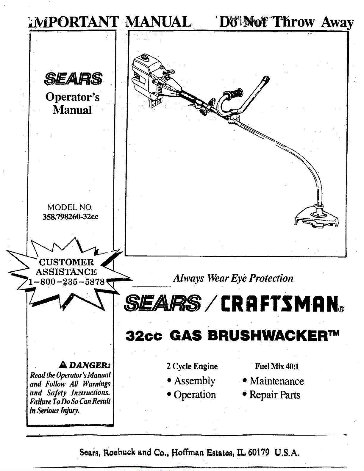
_IPORTAN_ MANUAL
Operator's
Manual
MODEL NO.
358.798260-32cc
_D__ brow
• CUSTOMER
ASSISTANCE "---
_1-800-235-5878 _ Always Wear Eye grotectWn
_-_ SE_,/AIk_S/ £RRFTSMRN®
32cc GAS BRUSHWACKER TM
Fuel Mix40:1
• Maintenance
• Repair Parts
A DANGER:
Read the Operator'sManual
and Follow All Warnings
and Safety Instructions.
Failure ToDo SoCanResuit
in Serious Injury.
2 Cycle Engine
• Assembly
• Operation
sears,RoebuckandCo., HoffmanEstates,IL 60179 U,S.A.
For one year from the date of purchase, when this Craf_man Gas-Powered Brushwaeker is maintained, lubricated, and tuned
up accordingto the operating and maintenance instructions in the operator's manual, Sears will repair, free of charge, any defect
in materials or workmanship. • •
This warranty excludes the blade, nylon line, spark plug, and air filter, which are expendable parts and become worn during
normal use.
If this Brushwacker is used for commercial purposes, this warranty applies for only 90 days from the date ofpurchase. If thin Brushwacker
is used for rental purposes, this warranty applies for only 30 days from date of purchase. Th_ warranty applie s only while this product is in
use in the United States.
WARRanTY SERVICE IS AVAILABLE BY RETURNING THE BRUSHWACKER TO THE _ST SEARS SERVICE CENTER IN THE
UNITED STATES.
This warranty gives you specific legal rights, and you may also have other rights which vary from state to state.
SEARS, ROEBUCK AND CO. DEPT.817WA HOFFMANESTATES, rL 60179
TABLE OF CONTENTS
;_VA--I_INGS,_6§T_E_r_ ;ir_sT_p_TioNs....._ ....._._.,..--3
F - owYOURTOOL......................................................S
ASSEMBLY....................................................................6
FUELhNG YOUR ENGINE ............................................ 11
STARTING YOUR ENGINE .................................... ...... 12
USING YOUR TOOL AS A BRUSIICUTTER ......... : ....... 14
USING YOUR TOOL AS A LINE TRIMMER ................. 16
ACCESSORIES ............ . ..... ;......................................... 20
CUSTOMER RESPONSIBILITIES ................................ 21
REPAIR PARTS LIST ................................................... 28
INDEX ............... . ......................................................... 3
2
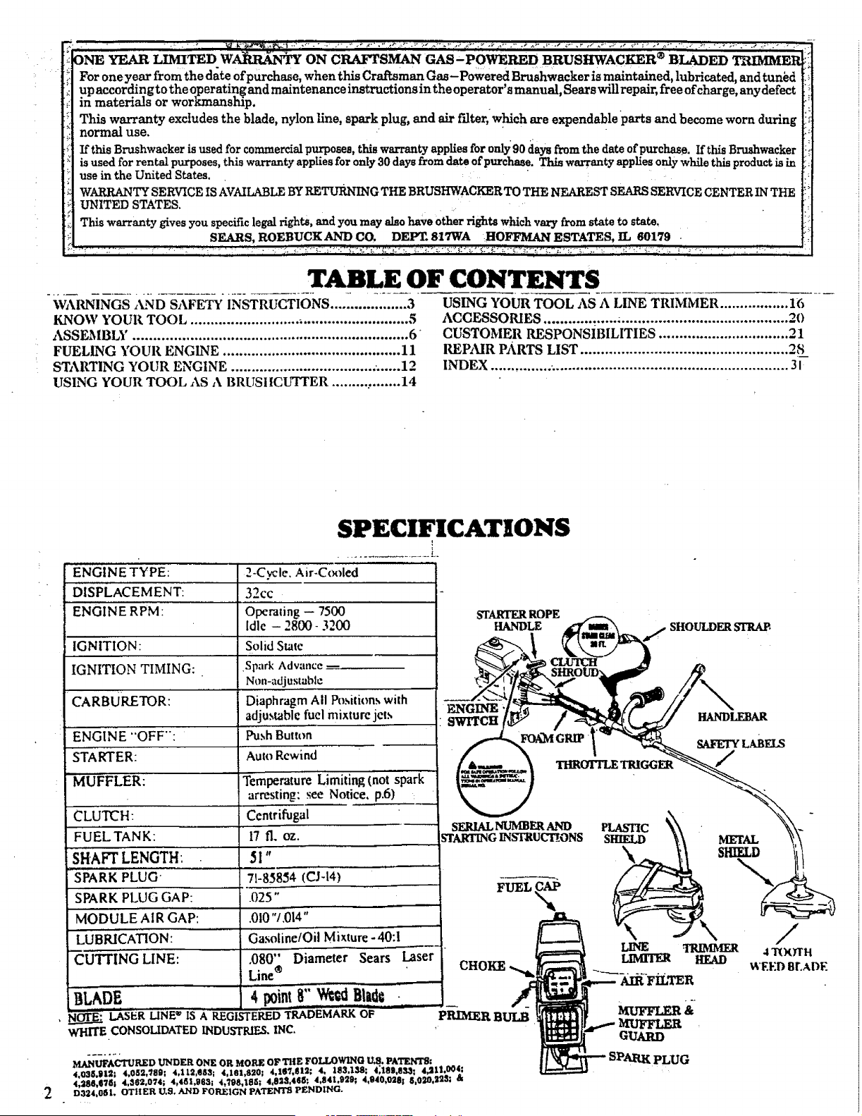
SPECIFICATIONS
"ENGINE TYPEi 2-C_l'e. Air-C(_fied
DISPLACEM ENT: 32¢c
RPM: Operating -- 7500
ENGINE
Idle - 2800- 3200
Solid State
IG NtTION:
IGNITION TIMING:
CARBURETOR:
"ENGINE "'OFF":
STARTER:
MUFFLER:
CLUTCH:
FuELTANK: ........
SHAFTL_NGTHi
SPARK PLUG"
SPARK PLUG GAP:
MODULEAIR'GAP:
LUBRICATION:
"CUTTING LINE:
Spark Advance --
Non-adjustable
Diaphragm All l_sitions with
adjustable fuel mixture jet.,,
Push Button"
Auto Rewind
Temperature 'Limiting (not spark
arresting; see Notice, p.6) :
Centrifugal ..........
17 ft. oz.
51"
71-8585'4 (Cj-t4) .....
.025"
.0t0 1.014
.... GasolinetOil Mixture-40:!
.080" Diameter Sears Laser
Line ®
BLADF, 4 pointB'"w_ Blatl_
I_ER LINE" IS A REGISTEREDTRA'DEMARK OF '"
WHITE CONSOLIDATEDINDUSTRIF._,INC.
STARTER ROPE
HANDLE SHOULDER STRAB,
SERIAL NUMBER AND PLASTIC
STARTINGINSTRUCt!ONS S_
X
FUEL _
CHOKE
MANLt_ACTTII_D UNDER ONE OR MOI_ OF THE FOI,,I_WI_(] LLS. PAI'g/ITS:
4,03_,!1121 4,0_2,'/8S; 4,II2,SS:I; 4,181,S_0; 4,1_ff, lll_; 4, 183,158; 4;1811,83,_1 4#111,004;
4,_SS,(I'/8| 4,362,074; 4,451,983; 4,'/98,t8_; 4,823,468; 4,S41,929; 4,S40,0281 8,0g0,225; &
D324,0Sl. OTItER U,S, AND FOREIGN PATENTS PENDING.
METAL
SHIELD
LINE TRIMMER
LIMrlXR HEAD
_-_ AIR-FiLTER
GUARD
SPARK PLUG
/
4 TOOTH
WEED BEADE
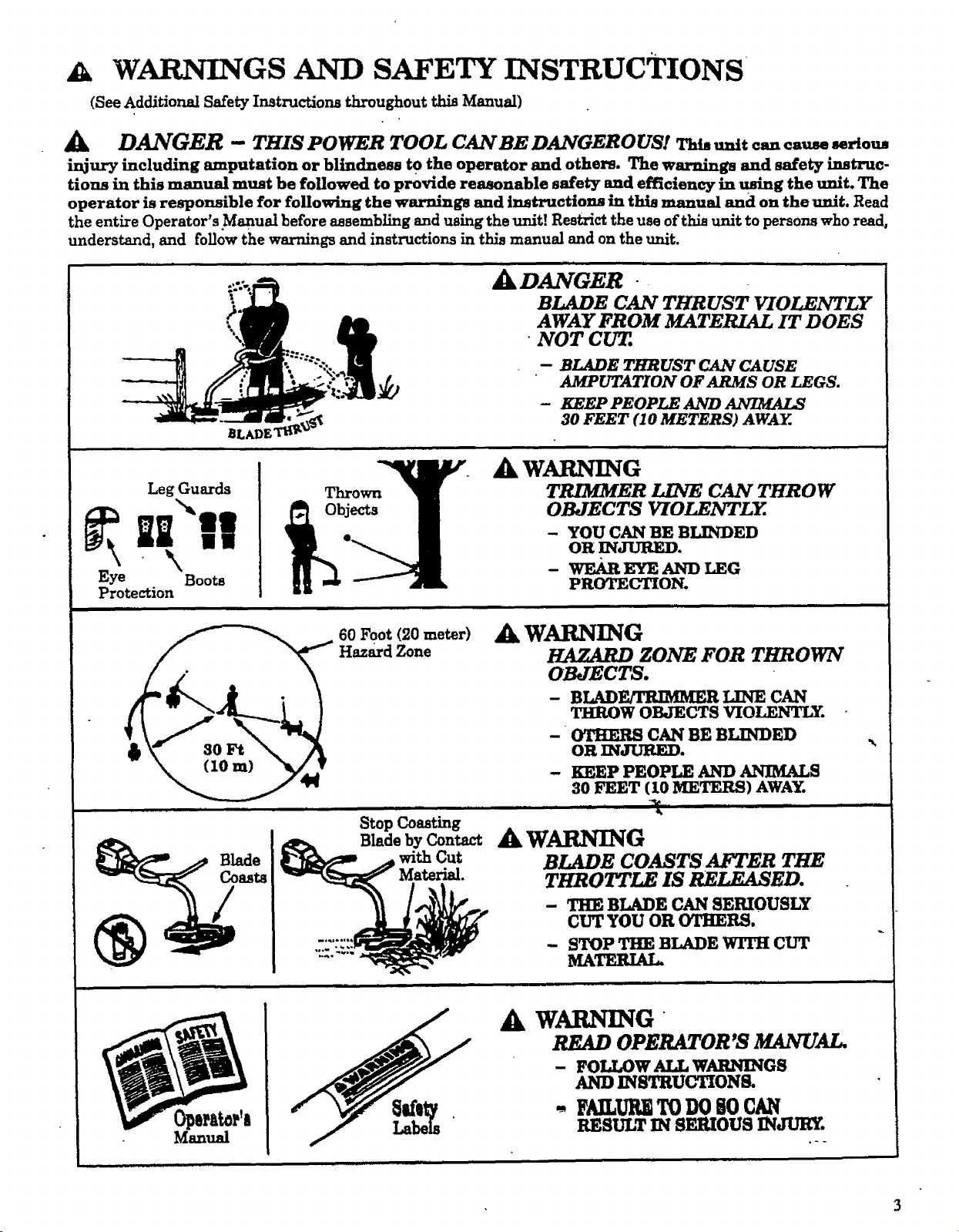
WARNINGS AND SAFETY INSTRUCTIONS
(See Additional Safety Instructions throughout this Manual)
Jk DANGER -- THIS POWER TOOL CAN BE DANGEROUS! Tht, unit ca,, cause serions
injury including amputation or blindness to the operator and others. The warnings and safety instruc-
tions in this manual must be followed to provide reasonable safety and efficiency in using the unit. The
operator is responsible for following the warnings and instructions in this manual and on the unit. Read
the entireOperator's.Manualbeforeassemblingand using theunit!Restricttheuse ofthisunitto personswho read,
understand,and followthe warnings and instructionsinthismanual and on the unit.
8LADE
Jik DANGER
BLADE CAN THRUST VIOLENTLY
AWAY FROM MATERIAL IT DOES
- NOT CUT.
-- BLADE THRUST CAN CAUSE
AMPUTATION OF ARMS OR LEGS.
- KEEP PEOPLE AND
30 FEET (10 METERS) AWAY.
i£ I "AWARN
Leg Guards Thrown_ TRIMMER LINE CAN THROW
• - YOU CAN BE BLINDED
OR INJURED°
- wE__ ANYLEG
Protection B PROTECTION.
in
60 Foot (20meter)
Hazard Zone
Jk WARNING
HAZARD ZONE FOR THROWN
OBJECTS.
- BLAD_ LINE CAN
THROW OBJECTS VIOLENTLY.
- OTHERS CAN BE BLINDED
OR INJURF_.
- KEEP PEOPLE AND ANIMALS
30 FEET (I0 METERS) AWAY.
,r r |1, ,r r , |, , ,,, I ' _ r
Stop Coasting
I_ Blade by Contact A WARNING
_/_ Blade __ _. with Cut BLADE COASTS AFTER THE
CUT YOU Ol
STOP THE I
MATERIAL.
TtlROTT_ IS RELEASED.
- THE BLADE CAN SERIOUSLY
CUT YOU OR OTHERS.
- STOP THE BLADE WITH CUT
• n nl ml i| i
%,
Manual
A WARNING
OPERATOR'S MANUAL.
- FOLLOW ALL WARNINGS
AND INSTRUCTIONS.
+ FAILURITODO80 CAN
RESULT IN SERIOUS INJURY.
WARNINGSAND S ETY INSTRUCTIONS....(Continued)
Ak OPERATOR SAFETY
• Always wear safety eye protection.
• Always wear heay3_ long pants, long sleeves,
boots, and gloves. Wearing safety leg guards is rec-
ornmended_ Do not go barefoot or wear sandals,
jewelry, short pants, short sleeves, loose clothing,
or clothing with loosely hanging ties, straps, tas-
sels, etc.; they can be caught in moving parts. Be-
ing fully covered will help protect you from pieces
of toxic plants such as poison ivy thrown by blade
or trimmer head which could be more of ahazard
than touching the plant itself.
• Secure hair so it is above shoulder length.
• Do not operate unit when you aretired, ill, or un-
der the influence of alcohol, drugs, or medication.
• Wear hearing protection if you use the unit for
more than 1-1/2 hours per day.
• Never start or run the engine reside a closed room
or building. Breathing exhaust fumes can kill.
• Keep handles free of oil and fuel.
• Alwaysuse the handlebar and a properly adjusted
shoulder strap with a blade. See '7_ssembly."
A UNIT/MAINTENANCE SAFETY
• Look for and replace damaged or loose parts be-
fore each use. Look for and repair fuel le_ before
use. Keep the unit in good working condition..
• Throw away blades that are bent, warped,
cracked, broken, or damaged in any other way.
Replace trimmer head parts that are cracked,
chipped, broken, or damaged in any other way be-
fore using the unit.
• Maintain the unit according to recommended pro-
cedures. Keep theblade sharp. Keep the cutting
Iine at the proper length.
• Use only .080" diameter SEARS Laser Line _.
Never use wire, rope, string, etc.
• Insta_ the required shield properly before using
the unit. Use the metal shield foor all weed blade
use. Use the plastic shield for all line trimmer use.
• Use only specified blade or trimmer head; make
sure it is properly installed and securely fastened.
• Never start engine with clutch shroud removed.
The clutch can fly off and cause serious i_ury.
• Be sure btade or trimmer head stops turning when
engine idles.
• Disconnect the spark plug befo_ performing
maintenance (except carburetor adjustments).
• Make carburetor adjustments with the lower end
supported to prevent the blade or trimmer line
from contacting any object. Hold the unit by hand;
do not use the _oulder strap for support.
• ' Keep others away when making carburetor ad-
justments ..........
• Use only genuine SEARSaccessories as recg_m--__
mended forthisunit. _
• Have all maintenance and service not explained
in this manual performed hy ar_ Authorized Ser-
vice Dealer.
A FUEL SAFETY
• Mix and pour fueloutdoors.
• Keep away from sparksor flames.
• Use a containerapproved forfuel.
• Do not smoke or allowsmoking near fuelor the
unitorwhile usingtheur.lt.
• Wipe up.allfuelspillsbeforestartingengine.
• Move at least10 feet(3meters)away from fueling
sitebeforestartingengine.
• Stop engineand allowunitto coolbeforeremov-
ingfuelcap.
• Empty the fueltank beforestoringtheunit.Use
up fuelleftin the carburetorby startingtheen-
gineand lettingit_ untilitstops.
• •Store unitand fuelm an area where fuelvapors
cannot reach sparks or open flames from water
heaters,electricmotors orswitches,furnaces,etc.
A CUTTING SAFETY
• Inspect the area to be cut before each use. Remove
objects(rocks,broken glass,nails,wire,string,
etc.)which can be thrown or become entangledin
thebladeor trimmer head.
• Keep othersincludingchildren,animals,bystand-
ers,and helpersoutsidethe 60 foot(20 meter)
Hazard Zone.Stop the engineimmediatelyifyou
areapp_ached. . •
• Always _ engine on the right-hand side of
our body. hands
• _Id theunitfirmlywith both
• Kee_ firm footingand balance.Do not over-
reacn.
• Keep blade or trimmer head below waist level.
• Do not raise the engine above your waist.
• Keep _l parts of your body away from blade, trim-
mer head, and muffler when engine is runnnmg.
• Cut from your rightto your left.
• Use onlyforjobsexplainedin thisman_laL
TRANSPORTING AND STORAGE
• S_p the unitbeforecarrying.
• Keep the muffleraway from your body.
• Allow engineto cooland secureunitbeforestor-
ing or transl_brtingitin a vehicle.
• Empty the fueltank beforestoringor transport-
ingthe unit.Use up fuelleftin the carb.ur.etorby
•s__e engineandlettingitrununtilitstops.
• Store unit and fuel in an area where fuel vapors
cannot re_h sparks or open flames from water
heaters,electricmotors or switches,furnaces,etc.
• Storeunitso thebladeor linelimitercannot acci-
denny causeinjury.The unit'canbe hung bythe
bracketbelow engineorby tube.
• Store the unit out of reac2x of children.
iii ill i inn i i ...,, ii i
,,.,,
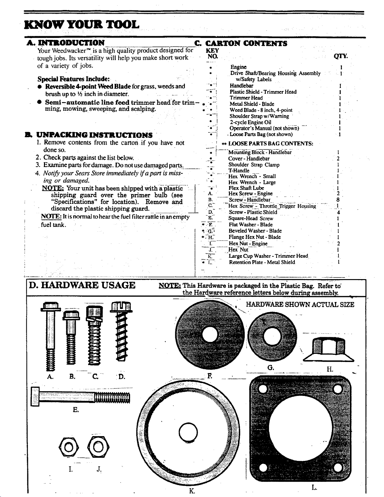
KNOW YOUR TOOL
ill IIIIIIIIII I IIH
Your Weedwacke:" is a high quality product designed for
tough jobs. Its versatility will help you make short work
of a variety of jobs.
Special Features Include: ,
• Reversible,l-point Weed Blade for grass, weeds and
brush up to ½ inch in diameter. ....... -
• Semi.automatle line feed trimmer laeadfor trim-.,-.-
ruing, mowing, Sweeping, and scalping ..... . • '
-,-'.j
B. UNPACKING INSTRUCTIONS " -'i
1. Remove contents from the carton if you lhave not
C. CARTON CONTENTS
KEY
done so.
2. Check part,sagainst the list below.
3. Examine partsfor damage. Do notusedamaged parts.
4. Notify your Sears Store immediately if a part is miss-
fuel tank.
Engine
Ddve Shaft/BearingHousing Assembly
w/Safety Labels
Handlebar
Plastic Shield- TrimmerHead
Trimmer Head
Metal Shield-Blade
Weed Blade - 8 inch, 4-point
Shoulder Strap w/Warning
2-cycle EngineOil
Operator's Manual(not shown)
.l._ose PartsBag (notshown)
** LOOSE PARTS BAG CONTENTS:
QTY,
1
1
......... 4 ....................
1
1
!
l
I
1
i
I
L,_-[)..... Moh-iii,ing Block- Handl-ebar 1
-4- Cover- Handlebar 2
ShoulderStrap Clamp !
- ;- T-Handle i
" - .... Hex Wrench - Small 1
ing or damaged. '-*' Hex Wrench - Large 1
Your unit has been shipped with abl_ie--" i - "-' Flex Shaft tube 1
shipping guard over the primer bulb (see I A. HexScrew-Engine 2
"Specifications"for location).Remove and i: B. - Screw_2Handlebar ...... 8
• discard the plastic shipping guard. __[_ C_ _.i_Hex'Se_-iThrdtt-le--'i;ri_er H0_using .... 1.
......... D, Screw- Plastic Shield 4
NOTE: It is normal to hear the fuel filter rattle in an empty -zS Square-Head Screw 1
* .:g . Fiat Washer - Blade I
'_I(G_ BeveledWasher - Blade 1
*;'H2 Flange Hex Nut -Blade i
) , '17" ._ Hex_Nut-E..ngine 2
---_J7-, Hex Nut 1
t_--'7-. -Large CupWasher - Trimmer Head 1
* -L_- Retention Plate - MetalShield 1
D. HARDWARE USAGE
--. q
NOTE'. This Hardware ispackaged in thePl_tic Bag. Referto"
the Hardware referencelettersbelow during assembly. _
-f
, HARDWARE SHOWN ACTUAL SIZE
• . T K°
L,
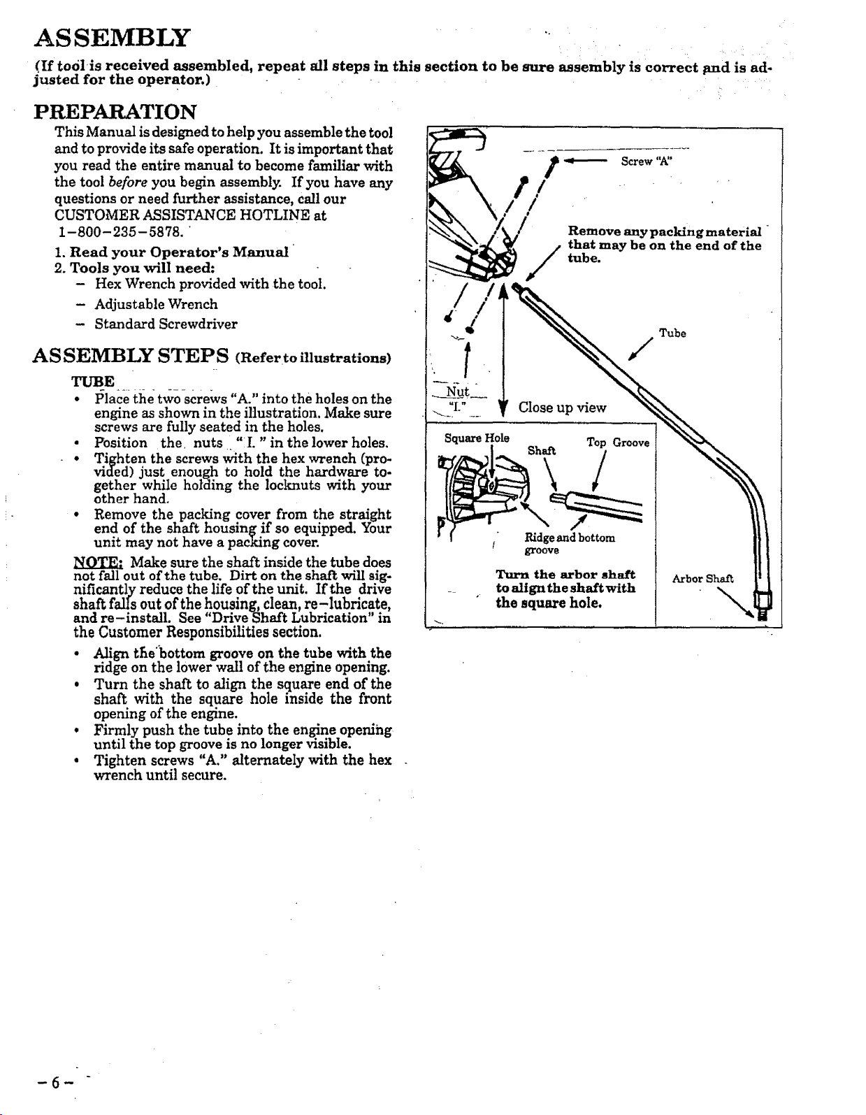
ASSEMBLY
(If toolis received assembled, repeat all steps in this section to be sure assembly is correct pad is ad-
justed for the operator.)
:i
PREPARATION
This Manual is designed to help you assemble the tool
and to provide its safe operation. It is important that
you read the entire manual to become familiar with
the tool before you begin assembly. If you have any
questions or need further assistance, call our
CUSTOMER ASSISTANCE HOTLINE at
1-800-235-5878.
1. Read your Operator's Manual _
2. Tools you will need:
- Hex Wrench provided with the tool.
- Adjustable Wrench
- Standard Screwdriver
ASSEMBLY STEPS (Refer to illustrations)
TUBE
• Place the two screws "A." into the holes on the
engine as shown in the illustration. Make sure
screws are fully seated in the holes.
• Position the. nuts. "l. "in the lower holes.
• • Tighten the screws with the hex wrench (pro-
vided) just enough to hold the hardware to-
gether while holding the locknuts with your
other hand.
• Remove the pacldng cover from the straight
end of the shaft housing if so equipped. Your
unit may not have a packing cover.
Make sure the shaft inside the tube does
not fall out of the tube. Dirt on the shaft will sig-
nificantly reduce the life of the unit. If the drive
shaft falIs out ofthe housing, clean, re-lubricate,
and re-install. See "Drive Shaft Lubrication in
the Customer Responsibilities section.
• Align the'_bottom groove on the tube with the
ridge on the lower wail of the engine opening.
• Turn the shaft to align the square end of the
shaft with the square hole inside the front
opening of the engine.
• Firmly push the tube into the engine opening
until the top groove is no longer visible.
• Tighten screws "A." alternately with the hex
wrench until secure.
9_..---- Screw "A"
. . ' • , •
,__ / Remove an, packin, materi._ "
that may be on the end of the
tube.
Ridgeand bottom
groove
Turn the arbor shaft
to align the shaft with
the square hole.
-6-
2. THROTTLE C_,dlll-_
_r.._IYI'ION:3 Do not kink the throttle cable ....... i
a: SlideFoamtheThrottleGrip. Trigger Housing away from the . ,_ _1 IIJ_r-I_ _ltf ....
'NOTE: Before performing step "b", push the barrel _ 0'__
_the throttle cable into the sheath until the _ ] [,,I,_q¢
barrel contacts the sheath. ' ! _.._'€_ I \,
b Insert the Throttle Cable through the tunnel in _he no, rsnno'_ Jl \
Foam Grip until the end of the Cable extends at ...... N: .... ],], aAu_n_
least 2 inches beyond :the Grip. TRIGGER j ], I _I_O'F"
c. Hold the Trigger away from the Drive Shaft Hous- -I- _._ C._LZ
ing and insert the barrel end of the Throttle Cable , '......................7--
into the round_ opening in the Trigger._.
-_-_E.:--°When inserting the barre! end °ft-he
Throttle Cable into the round opening in the
Trigger, make sure that the barrel is completely
inserted and the Throttle Cable is located in 'the split
in the Arm.
d. Push the Trigger back into the Housing while guid -
ing the Cable through the split in the art 9. Guide_
the arm into the Foam Grip tunnel while replacing,
the Throttle Trigger Housing trash againstthe Grip__
e. Hold Trigger_against the Foam Grip while insert-"
ing the screw "B." and Nut "I." See Caution below.
[CAUTION: ('Do notovertig-htenihe screw. Make
sure the trigger will move freely. There must be at •
least 1!8"free play in the trigger. Make sure the
trigger will move freely so the engine can fully
return to idle when the trigger is released. The--
trimmer head must not turn at idle_speed to avoid
serious injury to the operator and others.
3. HANDLEBAR •
ARM
Nut
alXWARNING
The handlebar mountingblock must be placed above the
point of the arrow on the safety labels. The handlebar
is a barrier to keep the blade away from the operator's
feet.
a. Position either side of the mounting block on the
drive shaft Housing above the arrow on the Safety
Labels.
b. Place one of the covers below the drive shaft Hous-
ing and secure it to the mounting block with 2
c. Align the Handlebar with the straight barrier por-
tion to the left and the curved portion to the right. _
d. Position the Mounting Block between the arrows
on the short, straight section of the Handlebar.
e. Place the remaining Cover over the Handlebar and
secur e it with two_re__WSs_iC_":,finger tightenordy.- [ .
f. Be sure the Handlebar is installed correctly, then
.... tighten each screw securely with a wrench.
AWMUIDI0
The long, straight portion of the Handlebar must be
installed to provide a barrier between the operator
and the spinning blade.
SAFETY
LABELS
/
:C
CABLE
I I I I illllIl I IIIIII
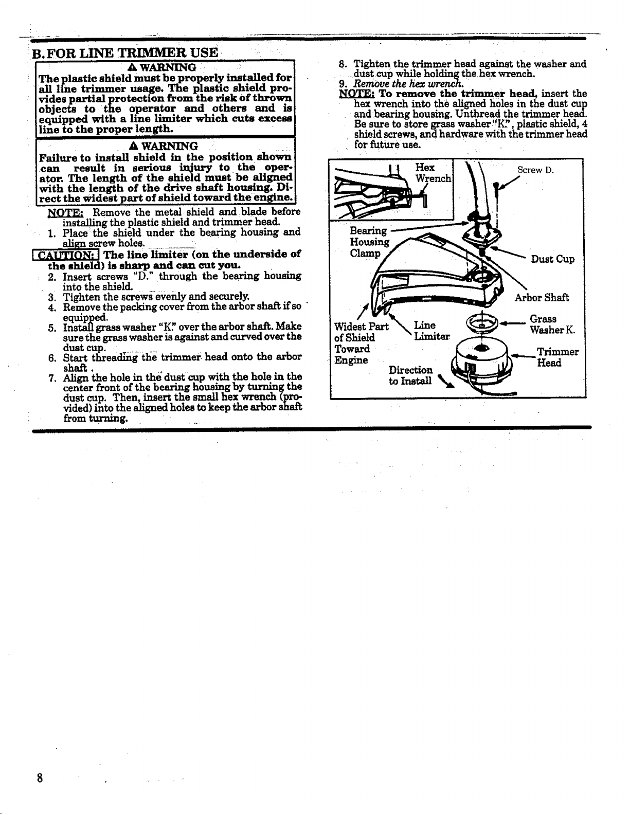
B.FOR LINE TRIMMER USE _ ,,:
: A WARNING
fiastic shield must be ' installed for
trimmer shield pro-
risk of thrown
ecte to operator and others and is
with a line limiter which cuts excess
the proper length.
AWARNI_G : ._.:
Failure to install shield in the position shown
can result in serious injury to the oper*
ator. The length of the shield must be aligned
with the length of the drive shaft housing. Di-
rect the widest part of shield toward the engine.
NOTE." Remove the metal shield and blade before
• installing the plastic shield and trimmer head.
1. Place the shield under the bearing housing and
_.align screw holes. .......... _=
The line limiter (on the underside of
the shield) is sharp and can cut you,
2. Insert screws "D." through the bearing housing
into the shield.
31 Tighten the screws evenly and securely.
4. Remove the packing cover from the arbor shai_ if so
equipped.
5. Install grass washer "K? over the arbor shaft Make
sure the grass washer is against and curved over the
dust cup.
6. Start thread_g tl_e trimmer head onto the arbor
shaft.
7. Align the hole in the dust cUp with the hole m the
center front of the bearing housing by turning me
dust cup. Then, insert the small hex wrench (pro-
vided) into the aligned holes to keep the arbor shat_
from turning.
8. Tightenthe trimmer head againstthewasher and
dustcup whileholdingthehex wrench.
9. RemOve the hex wrench.
To remove the trimmer head, insert the
hex wrench into the aligned holes in the dust cup
and bearing housing. Unthread the trimmer head.
Be sure to store grass washer"K?, plastic shield, 4
shield screws, and hardware with the trimmer head
for future use.
Bearing
Housing
Clamp
Hex
Screw D.
Dust Cup
!
Widest Part Line
of Shield
Toward
Engine
Direction
to Install
Arbor Shaft
Grass
Washer K.
Trimmer
8
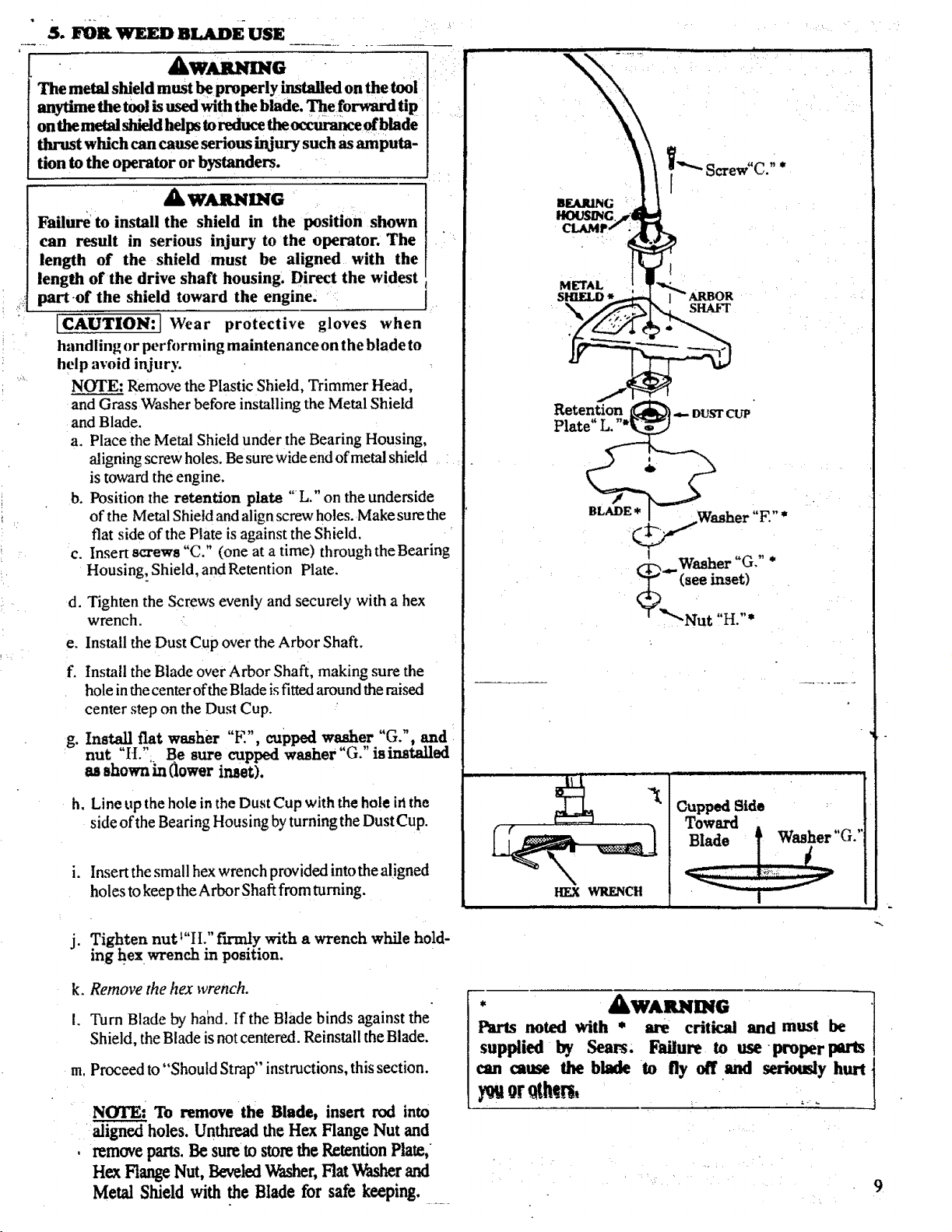
" S. mR WEEDnLADEUSE
The metal shield must _ properly installed on
anytime the tool is used with the blade. The forward tip
on the metal shield helps to reduce the _ of blade
thrust which can cause serious injury such as amputa-
tion to the operator or bystanders.
& w a,.NmG • • •
Failure to install the shield in the position shown
can result in serious injury to the operator. The
length of the shield must be aligned with the
length of the drive shaft housing. Direct the widest
part of the shield toward the engine. ::
[CAUTION:] Wear protective gloves when
handling or performing maintenance on the blade to
help avoid injury.
NOTE: Remove the Plastic Shield, Trimmer Head,
and Grass Washer before installing the Metal Shield
and Blade.
a. Place the Metal Shield under the Bearing Housing,
aligning screw holes. Be sure wide end of metal shield
is toward the engine.
b. Position the retention plate "L." on the underside
of the Metal Shield and align screw holes. Make sure the
flat side of the Plate is against the Shield.
c. Insert screws "C." (one at a time) through theBearing
Housing,. Shield, and Retention Plate.
d. Tighten the Screws evenly and securely with a hex
wrench.
e. Install the Dust Cup over the Arbor Shaft.
f. Install the Blade over Arbor Shaft, making sure the
hole in the center of the Blade is fitted around the raised
center step on the Dust Cup.
g. Install fiat washer E , cupped washer G. , and
.................. tailed
nut I L ; De sure cuppea WaSher t,. is ms
as shown in (lower inset).
h. Line up the hole in the Dust Cup with the hole iri the
side of the Bearing Housing by turning the Dust Cup.
i. Insert the small hex wrench provided into the aligned
holes to keep the Arbor Shaft from turning.
j. Tighten nut 1"II." fuanly with a wrench while hold-
ing hex wrench in position.
k. Remove the hex wrench.
I. Turn Blade by hahd. If the Blade binds against the
Shield, the Blade is not centered. Reinstall the Blade.
m, Proceed to "Should Strap" instructions, this section.
NOTE: To remove the Blade, insert rod into
aligned holes. Unthread the Hex Flange Nut and
, remove parts. Be sureto store the Retention Plate,
Hex FlangeNut, BeveledWasher,Flat Washer and
Metal Shield with the Blade for safe keeping.
/-r--, W88tle, r _.J,
"(see inset)
X _'Nut "H "*
Cupped Side
Toward
Blade _! washer .'
* £WARNING ]
Parts .no.ted with * are critical and must be
supphed by Sears. Failure to use proper parts
can cause the blade to fly off and seriously hurt
}_t or.qtMrs, :
9
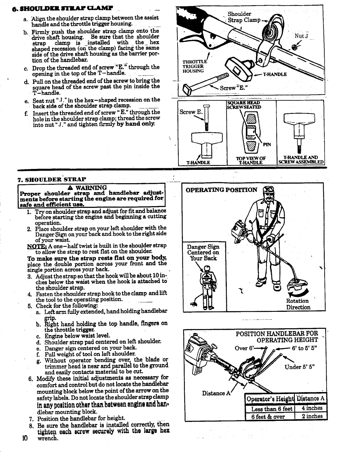
6. SHOULDgl STR.Ar _ ....
a. _gn the sh?ulder s_ap cIampbetween the assist
handle and the throttle trigger housing. ...........
b. Firmly push the shoulder strap clamp onto the
drive shaft housing. Be sure that the shoulder
strap clamp is installed with the hex
shaped recesmon (on-the clamp) facing the same
side of the drive shaft housing as the barrier por-
tion of the handlebar.
c. Drop.the threaded end of screw _"ES through the
opening in the top of the T-handle.
d. Pull on the threaded end of the screw to bring the
square head of the screw past the pin inside the
T-handle.
e. Seat nut ",l." in the hex-shaped recession on the
back side of the shoulder strap damp. ........
f. Insert the threaded end of screw "E." through the
hole in the shoulder strap clamp; thread the screw
into nut "J." and tighten fn_nly by hand only.
7. SHOULDERSTRAP
I. Try on shoulder strap and adjust for fit and balance
before starting the engine and beginning a cutting
operation.
2. Place shoulder strap on your left shoulder with the
Danger _ign on your back and hook to the right side
of your waist.
NOTE." A one-half twist is built in the shoulder strap
' to allow the strap to rest fiat on the shoulder.
To make sure the strap rests fiat on your bo_v,
place the double portion across your front and the
single portion across your back.
3. Adjust the strap so that the hook will be about 10 in-
ches below the waist when the hook is attached to
the shoulder strap.
!4. Fasten the shoulder strap hook to the clamp and lift
the tool to the operating position.
5. Check for the foUowing_.
a. Leftarm fully extended, handholdinghandlebar
grip.
b. Right hand holding the top handle, fingers on
the throttle trigger.
c. Engine below waist level.
d. Shoulder strap pad centered on left shoulder.
e. Danger sign centered on your back
f. Full weight of tool on left shoulder.
g. Without operator bending over, the blade or
trimmer head is near and parallel to the ground
and easily contacts material to be cut.
6. Modify these initial adjustments as necessary for
comfort and control but do not locate the handlebar
mounting block below the point of the arrow on the
safety labels, Do not locate the shoulder strap clamp
in anypoaiti0notherthanb0tw n on o andban.
dlebar mounting block.
7. Position the handlebar for height.
8. Be sure the handlebar is installed correctly, then
tighten each acrew _urely with the large hex
wrench.
Shoulder
Strap
OPERATING POSMOH
Danger Sign
Centered on
Your Back
Rotation
Direction
POSITION HANDLEBAR FOR
_. , OPERATING HEIGHT "
Over 6 4---- 6' to 5' 5"
I I II III II I II I BI II BIBLE llll IIIIIIIII I I I IIIIIII lllllll I IIIIII IIIIII
,i i iii , H ,,,,,,,,,,
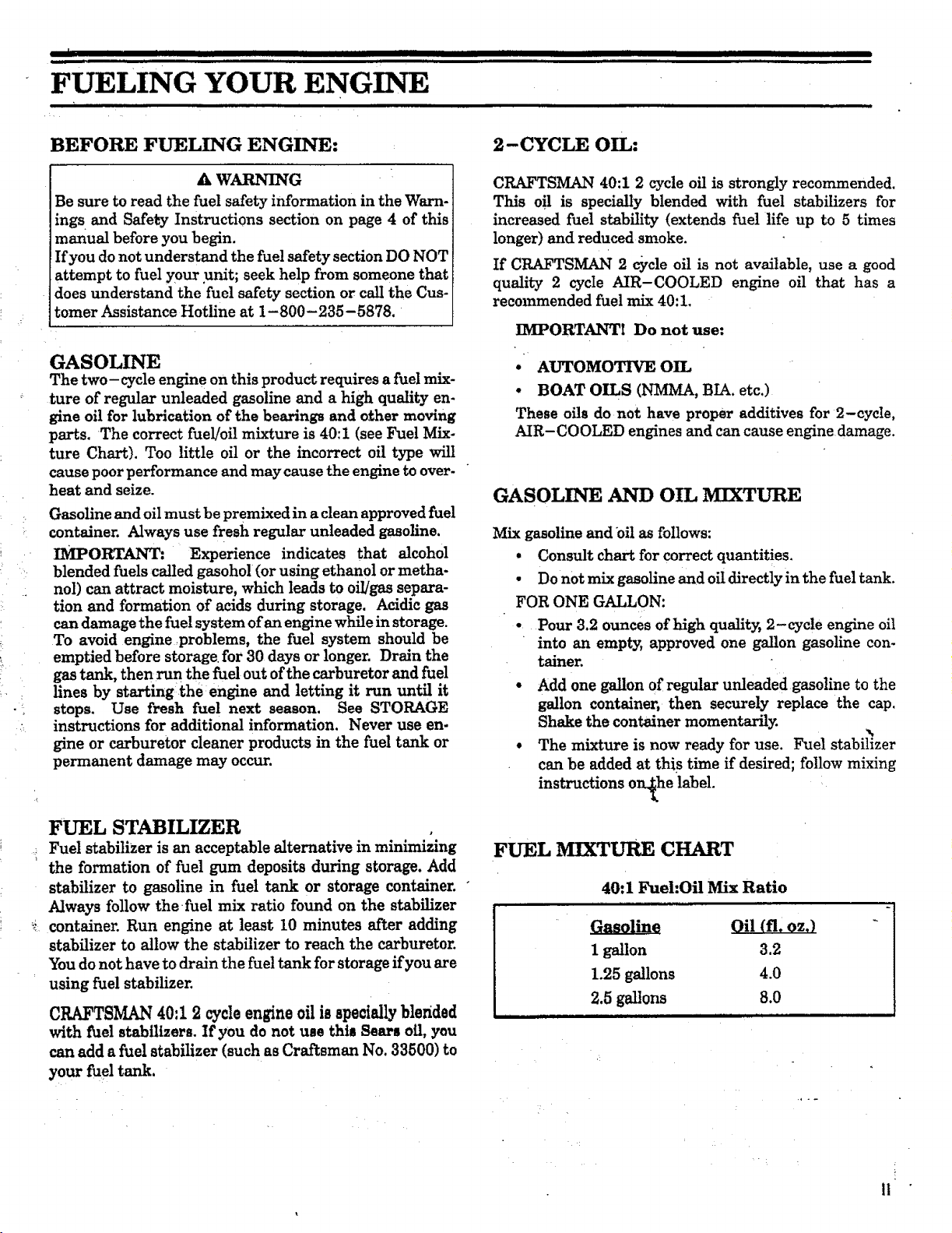
FUELING YOUR ENGINE
BEFORE FUELING ENGINE:
A WARNING
Be sure to read the fuel safety information in the Warn-
ing s and Safety Instructions section on page 4 of this
manual before you begin.
If you do not understand the fue! safety section DO NOT
attempt to fuel your unit; seek help from someone that
does understand the fuel safety section or call the Cus-
tomer Assistance Hotline at 1-800-235-5878.
GASOLINE
The two-cycle engine on this product requires a fuel mix-
ture of regular unleaded gasoline and a high quality en-
gine oilforlubrlcal;ionofthe bearingsand othermoving
parts.The correctfuel/oilmixture is40:1 (seeFuel Mix-
ture Chart).Too littleoilor the incorrectoiltype will
cause poorperformance and may causetheenginetoover-
heat and seize.
Gasolineand oilmust be premixedina cleanapprovedfuel
container.Always use freshregularunleaded gasoline.
IMPORTANT: Experience indicatesthat alcohol
blendedfuelscalledgasohol(orusingethanolormetha-
nol)can attractmoisture,which leadsto oil]gassepara-
tionand formation ofacidsduring storage.Acidicgas
can damage thefuelsystem ofan enginewhileinstorage.
To avoid engine ,problems,the fuelsystem should be
emptied beforestoragefor30 days or longer.Drain the
gastank,then run thefueloutofthecarburetorand fuel
linesby starting;theengineand lettingitrun untilit
stops. Use fresh fuel next season. See STORAGE
instructionsforadditionalinformation.Never use en-
gine or carburetorcleanerproductsin the fueltauk or
permanent damage may occur.
FUEL STABILIZER
Fuel stabilizer is an acceptable alternative in minimizing
the formation of fuel gum deposits during storage. Add
stabilizer to gasoline in fuel tank or storage container.
Always follow the fuel mix ratio found on the stabilizer
container. Run engine at least 10 minutes after adding
stabilizer to allow the stabilizer to reach the carburetor.
You do not have to drain the fuel tank for storage if you are
using fuel stabilizer.
CRAFTSMAN 40:1 2 cycle engine oil is specially blended
with fuel stabilizers. If you do not use this Sears off, you
can add a fuelstabilizer(suchas Craftsman No. 33500)to
your fueltank.
2-CYCLE OIL:
CRAFTSMAN 40:1 2 cycle oil is strongly recommended.
This off is specially blended with fuel stabilizers for
increased fuel stability (extends fuel life up to 5 times
longer) and reduced smoke.
If CRAFTSMAN 2 c_ycle oil is not available, use a good
quality 2 cycle AIR-COOLED engine oil that has a
recommended fuel mix 40:1.
IMPORTANT! Do not use:
* AUTOMOTIVE OIL
. BOAT OILS (NMMA, BIA. etc.)
These oilsdo not have proper additivesfor2-cycle,
AIR-COOLED enginesand can causeenginedamage.
GASOLINE AND OIL MIXTURE
Mix gasoline and oil as follows:
• Consult chart for correct quantities.
• Do not mix gasoline and oil directly in the fuel tank.
FOR ONE GALLON:
• Pour 3.2 ounces of high quality, 2-cycle engine oil
into an empty, approved one gallon gasoline con-
tainer.
• Add one gallon of regular unleaded gasoline to the
gallon container, then securely replace the cap,
Shake the container momentarily.
• The mixture is now ready for use. Fuel stabilizer
can be added at this time if desired; follow mixing
instructions o_he label.
FUEL MIXTURE CHART
40:1 Fuel:Oil MAx Ratio
Gasoline Oil (ft. oz.) - -iJ
[
1 gallon 3.2
1.25gallons 4.0
2,5gallons 8.0
II
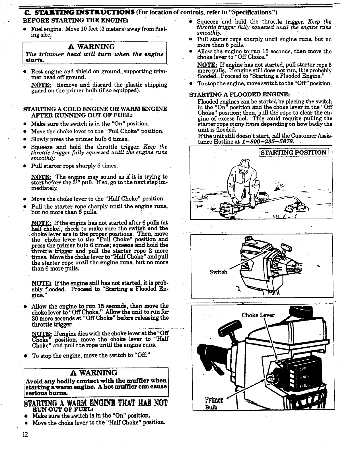
BEFORE STARTING THE ENGINE:
e Fuel engine. Move 10 feet (3 meters) away from fuel-
ing site.
The trimmer head will turn when the engine
starts.
• • r
i i
C. STAITING'INSTRUCTIONS (For location of controls, refer to "Specifications")
• Rest engine and shield on ground, supporting trim-
: mer head off ground.
Remove and discard the plastic shipping
guard on the primer bulb (if so equipped).
STARTING A COLD ENGINE OR WARM ENGINE
AFTER RUNNING OUT OF FUEL:
• Make sure the switch is in the "On" position.
• Move the choke lever to the "Full Choke" position,
• Slowly press the primer bulb 6 times.
• Squeeze and hold the throttle trigger. Keep the
throttle trigger fully squeezed until the engine runs
smoothly.
• PulI starter rope sharply 5 times.
NOTE." The engine may sound as ifitistryin_to
start before the 5TM pull. If so, go to the next step :m-
mediately.
• Move the choke lever to the "Half Choke" position.
• Pu_:the starter rope sharply until the engine runs,
but no more than 6 pulls.
If the engine has not started al_er 6 pulls (at
half choke), check to make sure the switch and the
choke lever are in the proper positions. Then, move
the choke lever to the "Full Choke" position and
press the primer bulb 6 times; squeeze and hold the
throttle trigger and pull the starter rope 2 more
times. Move the choke lever to "Half Choke" and pull
the starter rope until the engine runs, but no more
than 6 more pulls.
NOTE.* Ifthe enginestillh,asnot Started,itisprob-
ably flooded. Proceed to Startinga Flooded Eno
gine."
Allow the engine to run 15 second_, then move the
chokelever to "0ffChoke." AHow the unit torun for
30 more seconds at "Off Choke" before releasing the
throttle trigger. .................
]N_Q_rEI Ifengine dies with the choke lever at the "Off
Choke" position, move the choke lever to "Half
Choke" and pull the rope until the engine runs.
To stopthe engine,move the switchto "Off."
A WARNING
Avoid any bodily contact with the muffler when
starting a warm engine. A hot muffler can cause
serious burns.
ST O A WARMENOINB'THATHAS
Rt_ OUT OF FU'_L,
• Make sure the switch is in the "On" position.
• Move the choke levertothe "HalfChoke" position.
illll
• Squeeze and hold the throttle trigger. Keep the
throttle trigger fully squeezed until the engine runs •
smoothly.
• Pull starter rope sharply until engine runs, but no
more than 5 pulls.
• Allow the engine to run 15 seconds, then move the
choke lever to "Off Choke."
NOTE." Ifenginehas notstarted,pullstarterrope5
more pulls.Ifenginestilldoes notrun,itisprobably
flooded.Proceed to"Startinga FloodedEngine."
To stoptheengine,move switchtothe"Off"position.
STARTING A FLOODED ENGINE: " •
Floodedenginescan be startedby placingtheswi,:tch
inthe "On '_positionand the choke leverin the Off
Choke" position;then,pullthe ropeto cleartheen-
gine of excessfuel.This couldrequirepullingthe
starterropemany timesdependingon how badlythe
unit is flooded.
If the unit still doesn't start, call the Customer Assis-
tance Hotline at 1-800-235-5878,
!STARTING POSITION t
Switch
Choke Lever
12
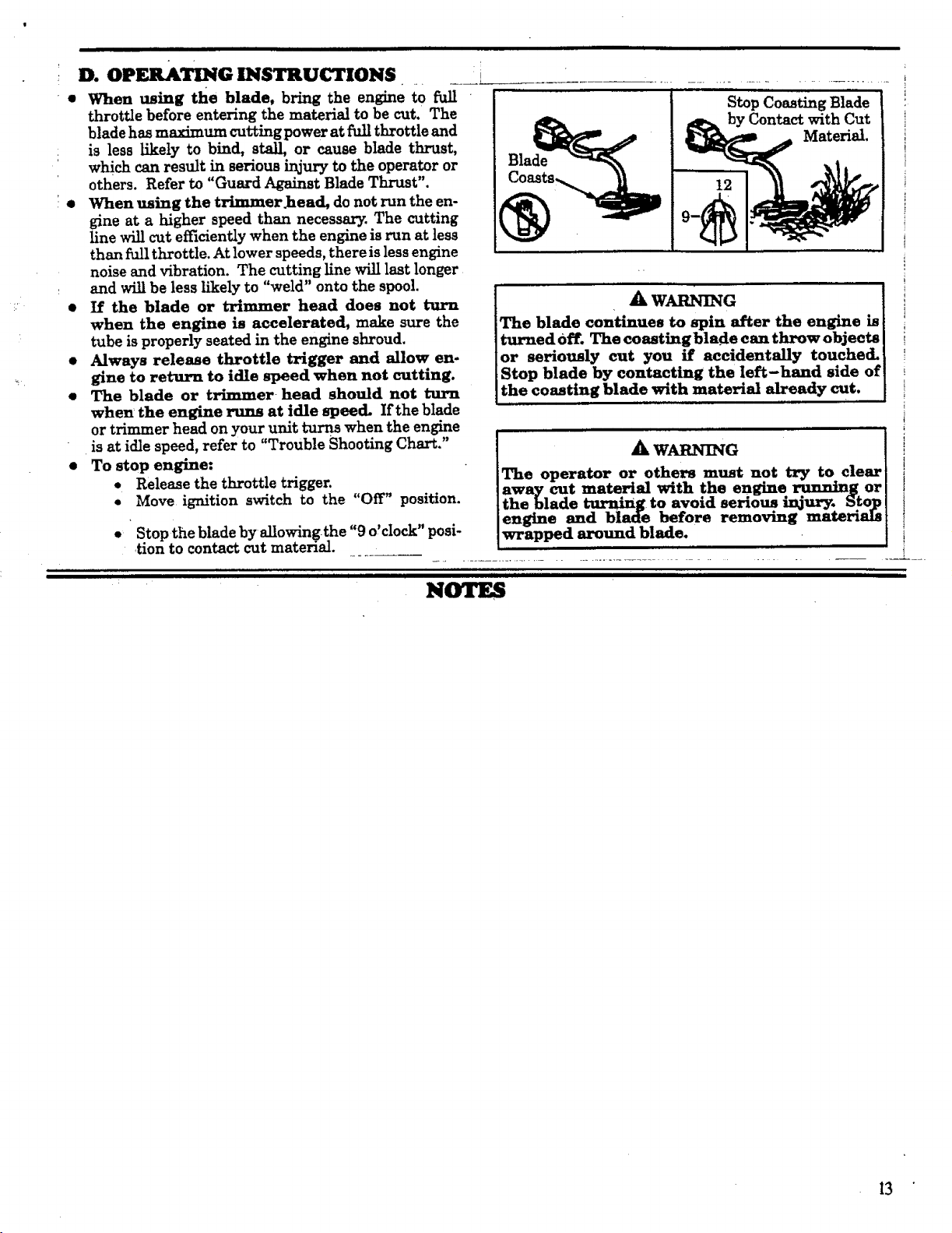
D. OPERATING INSTRUCTIONS
• When using the blade, bring the engine to fi_
throttle before entering the material to be cut. The
i
blade has maximum cutting power at full throttle and
is less l_ely to bind, stall, or cause blade thrust,
which can result in serious ir_jury to the operator or
others. Refer to "Guard Ag_i_t Blade Thrust".
• When using the trimmer_ead, do not run the en-
gine at a higher speed than necessary. The cutting
line will cut efficiently when the engine is run at less
than full throttle. At lower speeds, there is less engine
noise end vibration. The cutting line will last longer
and will be less likely to "weld" onto the spool.
• If the blade or trimmer head does not turn
when the engine is accelerated, make sure the
tube is properly seated in the engine shroud.
• Always release throttle trigger and allow en-
gine to return to idle speed when not cutting.
• The blade or trimmer head should not turn
when the engine runs at idle speed. Ifthe blade
or trimmer head on your unit turns when the engine
is at idle speed, refer to "Trouble Shooting Chart."
• To stop engine:
• Release the throttle trigger.
• Move ignition switch to the "Off" position.
Blade
12
Stop Coasting Blade
by Contact with Cut
Material.
The blade continues to spin after the engine is
turned Off. The coastingblade can throw objects
or seriously cut you ff accidentally touched.
Stop blade by contacting the left-hand side of
the coasting blade with material already cut.
_k WARNING
* Stop thebladeby allowingthe"9 o'clock"posi-
tiontocontactcut material.
The operator or others must not try to clear
away cut material with the engine running or
the blade turnin" g to avoid serious, injury. Sto_p
engine and blade before removing materials
wrapped around blade.
ii ill ii I i i I IIiiil I i I lllU II IIIIIIIIIIIIIIIIIIIIIIIIIIIIIIIIIIIIIIIIIII II IIIIIIII
13
USING YOUR TOOL AS A WEEDCUTTER - wfBLADE
(The 4 point, 8 inch blade is designed to cut grass, weeds and woody brush up to 1/2 inch diameter.)
Ak DANGER -THIS POWER TOOL CAN BE DANGEROUS!
This tool can cause serious injury including amputation or blindness to the operator and others. The warnings and safety
instructions in this manual must be followed to provide reasonable safety and efficiency in using this tool. The operator is
responsible.for following the warnings and instructions in this manual and on the tool. Read the entire Operator's
Manual before using this tool! Restrict the use of this power tool to persons who read, understand and
follow the warnings and instructions in this manual and on the tooL
7 .......................
• i'
BLADE THRUST
/_-__ I" ARBOR
8 inch WEED BLADE
,, I
60 Foot
. \ zo.
"-22J"
S_,pco._gBl_
B_ _by Contactwith Cut
__@_ Material.
_k DANGER - BI.ADE THRUST When the spin'
ning blade contacts anything it doesnot cut, a dan-
gerous reaction can occur causing the entire tool and
.... operator to be thrust violently in any direction. This
reaction is called Blade Thrust. As a result, the op'
erator can lose control of the tool. Use handlebar,
shoulder strap, and keep shield in place.
Make sure others are at least 30 feet (10 me-
ters) away. Keep blade sharp. Cut at full..
throttle and from your right to left. Keep
hands, feet and tool in proper position; refer to
"Guard Against Blade Thrust."
_k DANGER - PROPER BLADE
Us e only the 4point, 8 inch blade and proper
hardware. The use of any other parts can result in
serious injury. Do not use any accessory or ab
tachment other than those recommended by
the manufacturer for use with th_s tool. Blades
that are bent, warped, cracked, broken, or damaged
can fly apart and cause serious injury:Do not use.
Throw away.
_k WARNING - THROWS OBJECTS
The rapidlymoving blade causes objects tO be
thrown violently.The shieldwillnot providecom-
pleteprotectionto the operatororothers.The op-
erator must wear a safety face shield or gog-
eS, Always wear safetyleg guards and boots. °
ep others at least 30 feet away.
WARNING - HAZARD ZONE
This tool will throw ob_yts and cut. Keep others
including chl]dren, animals, bystanders, and
helpers at least 30 feet (10 meters) away from
the operator and tool. Stop the engine and
blade immediately if you are approached.
NOTE: In areas where other people and animals are
present, such as near sidewalks, streets, houses, etc.,
,t is strongly recommended that the operator use the
buddy system; that is, have another person serve as
a "look out," keeping himself and others at least 30
feet (I0meters) away from the operator.
lk WARNING - COASTING BLADE
The blade continues to spin after the engine is
stopped or the throttle is released. The coasting
blade can thrust, throw objects, or seriously cu.t you
if accidentally touched. Stop blade by leaving ,t
in contact with material already cut. Use the
"9 o'clock" potition u the point of contact.
14

A. BLADE SAFETY
1. OPERATOR SAFETY
a. Always wear a safety face shield or gog.
gles. See "Accessories,"
b. Always wear heavy, long pants, long
sleeves, boots, gloves and safet_y leg
guards. See Accessories." Do not wear loose
clothing, jewelry, short pants, short sleeves,
sandals, or go barefoot. Secure hair so it is
above shoulder length.
c. Do not operate this tool when you are
tired, iH or under the mfluence of alco-
hol, drugs or medication.
d. Always use the handlebar and a properly
adjusted shoulder strap. See '_seml_ly."
e. Do not swing the tool with such force
that you are m danger of losing your bal-
8lice.
f. Never start or run the engine inside a
closed room or building. Breathing exhaust
fumes can kill.
g. Keep handles free of oil and fuel.
2. TOOL SAFETY
a. Inspect the entire tool before each use.
Replace damaged parts.Check for fuelle_
and make sureallfastenersareinplaceand se-
curelyfastened.
b. Be sure the metal shield is properly at-
tached. The metal shield must be installed for
:_: all bladeusage.
c. Mak_sure the blade is properly installed
and securely fastened. Refer to _'Assembly."
d. Be sure the blade stops turning when the
engine idles. See "Trouble Shooting Chart."
e. Make carburetor adjustments with the
lower end supported to prevent the blade
from contacting any object. Hold tool by
hand; do not use shoulder strap for support.
f. Keep others away when making carbure-
3. CUTTING SAFETY ....
a. Inspect the area to be cut before each
use. Remove objects (rocks, broken glass,
nails, wire, string, etc.) which can be thrown or
become entangled in the blade.
b. Always keep the engine on the right side
of your body. Hold the tool rh-mly with both
"hands.
c. Keep firm footing and balance. Do not
over-reach.
d. Keep blade below waist level.
e. Do not raisethe engine above your waist.
The bladecan come dangerouslyclosetoyour
body.
f. Cut at full throttle.
g. Cut from your right to your left.
h. Use only for jobs explained in this man-
ual. Do not use the blade as an edger. The
shield does not provide adequate protection.
B. GUARD AGAINST BLADE THRUST
• Blade Thrust isa reactionthatonlyoccurswhen
usin$ a bladedtool.This reactioncan cause seri-
ous Lr_urysuch as amputation.CarefuU__ystudy.
thissection.Itisimportantthatyou understand
••what causesbladethrust,how you can reducethe
chanceofitsoccurring,and how you canremain
incontrolofthetoolifbladethrustoccurs.
• The forward tip on the shield helps to reduce the
occurrence of blade thrust but cannot prevent the
occurrence. The operator must follow the warn-
ings and safetyinstructionsin this section_to
lessenthechance ofb!adethrustoccurringand to
maintaincontrolofthetoolifthereactiondoesoc-
cur.
le
WHAT CAUSES BLADE THRUST. B/ade
Thrust can occur when the spinningblade con-
tacts an object that it does not cut. This contact
causes the blade to stop for an instant and then
suddenly move or"thrust" away from the object
that was hit. The thrusting" reaction can oe vio-
lent enough to cause the operator to be propelled
in any direction and lose control of the tool. The
uncontrolled tool can cause serious injury if the
blade contacts the operator or others.
2. WHEN BLADE THRUST OCCURS. B_
thrust can occur without warning if the blade
snags,sta_, orbin&. The. ismo_ik_y, to_cur
inarouwhereitiadiffi_Itto_ _o ma_ oe-
ing cut. By using the tool properly, the occurrence
of blade thrust will be reduced and the operator
will be less likely to lose control.
LADE THRUST
3. REDUCE THE CHANCE OF BLADE THRUST
a_ Cut only grass, weeds and woody- brush up
to 1/2 inch diameter. DO not let the blade con-
tact material it cannot cut such as stumps, rocks,
fences, metal, etc., or clusters of hard, woody
brush having a diameter greaterthan i/2inch.
b. Keep the blade sharp. A dullblade ismore
likelytosnag.
c. Cut only a fullthrottle.The blade_ m.axi-
mum cutting power at full throttle and is less
likely to bind or stall.
d. "INmd" the blade deliberately and not too
rapidl_ The blade can thrust away if it is fed too
rapimy.
e. Cut only from your right to left. Swingingthe
t0olinthe same direeti6n as the bladespins in.
creasesthe cuttingaction.
4. MAINTAIN CONTROL
a. Use the shoulder strap and keep a firm
gri'p o.n _ne tool .with both h andL A prop-
erly .adjustea snoulder strap will support the
weightofthetool,free'mgyourarms and hands
tocontroland guidethecuttingmotion.
b. Keep feet c omi'ortabl_ spread apart and
braced for the possibility of a sudden, rapid
thrust of the tool. Do not overreach. Keep firm
footing and balance.
C. CUTTING METHODS
c. E:e .ep the blade below waist level. It willbe
earner to maintain control of the tool.
d. Do not raise the engind above your waist
as the blade can come dangerously close to
your body.
e. Do not swing the tool with such force
that you are in danger of losing your bal.
anceo
?
1. Establish a rhythmic cutting procedure.
a. Plant feet firmly, comfortably apart.
b. Cut while swingingtheupperpart ofyourbody
from right to left.
c. Move forward to the next area to be cut after
the return swing and plant feet once more.
2. Use the 8 o'clock to 10 o'clock position for
cutting.
3. Stop the engine and_blade, then unclip the
snotuaer strap from the tool before clearing
cut material.
4. To reduce the chance of material wrapping
around the blade, follow these steps:
a. Cut at full throttle.
b. Swing the toolintomaterialto be cut from
your rightto left.
c. Avoidthe materialjustcutasyou make there-
turn swing.
A, WARNING
Direction toCut
The operator or othe_m must not try to elem
away cut material with the engine running ox
the blade turning to avoid serious injur_ _to_
engine and blade before removing materiah
wrapped around blade.
i i
n i uu
__I 0 Foot
(20meter)
Hazard Zone
Semi-Automatic Trimmer Head
(seeAccessoryList forpart number)
Use Only Genuine
Replacement Parts
A
A
I III Ill III II I Ilrll| II
A. LINE TRIMMER SAFETY
1. OPERATOR SAFETY
a. Always wear eye protection, when operating,
_rvi_ing,or p_rformingrnmntenanc_ on your
The operator must wear a safety face
shmld _or goggles. Always wear hea_y,
longpants and boots. Keep others at least
30 feet (10 meters) away.
WARNING - HAZARD ZONE
This tool will throw objects and cut. Keep oth-
ers including children, animals, bystand-
ers and helpers at least 30 feet (10 meters)
away from the operator and tool. Stop
the engine if you are approached.
WARNING- DAMAGED
• TRIMMER HEAD
Trimmer head parts that are chipped, cracked
or damaged in any other way can fly apart and
cause serious injury. Do not use. Replace
: damaged parts before using the tooL
I I II I i iluinnnnnn i
-i
b. Do not operate this tool when you are tired, ill
or under the influence of alcohol, drugs, or.
medication,
Leg Guards "%__hrown WARNING-THROWS OBJECTS
elf Obj_ t
The rapidly movingline causes objects to be
thrown violently. The shield will not provide
complete protection to the operator or 6thers.
USING YOUR UNIT AS A LINE TRIMMER ....
c. Always wear heavy, long pants, boots, and
gloves. Do not go barefoot or wear sandals,
• short pants, jewelry, loose clothing, or clothing
with looselyhanging straps,ties,tassels,etc.;
they can be caught in moving parts. Secure
hairso itisabove shoulderlength:Beingfully
covered willhelp protectyou from piecesof
toxicplantssuch as poisonivythrown by the
blade,which could be more of a hazard than
touchingtheplantitself.
d. Do not swing thetoolwith such forcethatyou 3.
arein danger oflosingyour balance.
e. Never startor run the engine insidea closed
room or building.Breathing exhaust fumes
can kill.
f. Keep handles freeof oiland fuel.
2. TOOL SAFETY
a. Inspectthe entiretoolbeforeeach use. Re-
placedamaged parts.Check forfuelleaksand
make sure allfastenersare in placeand se-
curelyfastened.
b. Use only.080"diameterSEARS LaserLine.Never
usewire,rope,string,etc.
c. Be surethe shieldisproperlyatta_ch_d,
d. Make sure trimmer head isproperlyinstalled
and securelyfastened.Referto '7_ssembly."
.............................H_ _ H,,,_ _ HH,_,, II I lillIIIIIIIIIIIIIIIIIIIIIIIII
e. Be sure trimmer head stops turning when en-
gine idles. See "Carburetor Adjustments."
fo Make carburetor adjustments with the drive
shaft housing supported to prevent the trim-
mer line from contacting any object.
g. Keep others away when making carburetor ad-
justments. _/ ......
h. Use o_y accessories or attachments as recom-
mended by Sears for2his tool.
CUTTING SAFETY
a. Inspect the area to be cut before each use. Re-
move objects (rocks, broken glass, nails, wire,
string, etc.) which can be thrown or become en-
tangled in the trimmer head.
b. Always keep the engine on the right side of
your body.
c. Hold the toolfirmlywith both hands.
d. Keep firm footingand balance.Do not over-
reach.
e. Keep thetrimmer head below waistlevel.
f. Do not raisetheengineabove your waist.
g. Keep allpartsofyourbody away from thetrim-
mer lineand mufflerwhen engineisrunning.
h. Use onlyforjobsexplainedinthismanual.
I IIII I II I III
B. TRIMMER LINE ADVANCE
Q
O
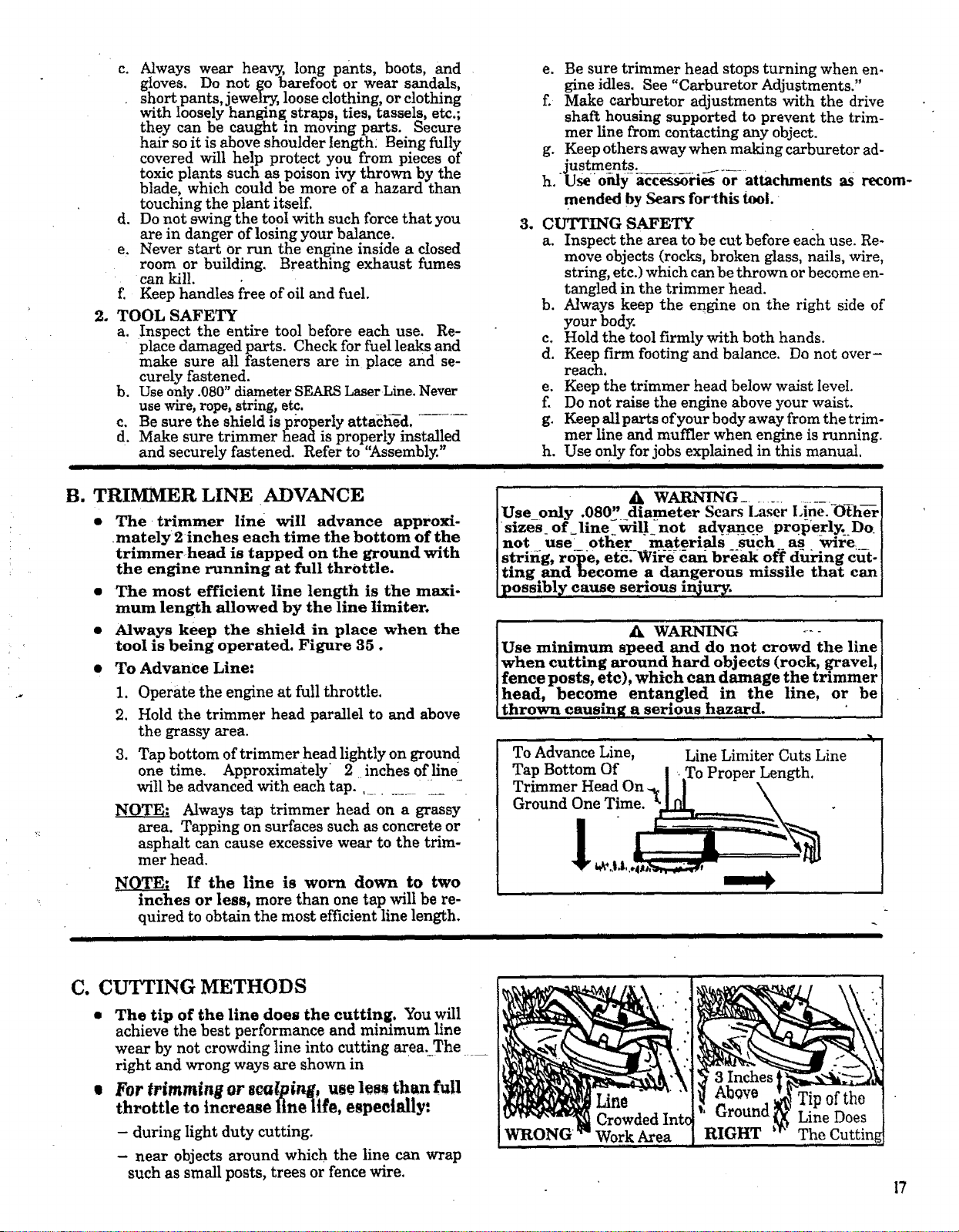
The _trimmer line will advance approxi-
mately 2 inches each time the bottom of the
trimmer head is tapped on the ground with
the engine running at full throttle.
The most efficient line length is the maxi-
mum length allowed by the line limiter.
Always keep the shield in place when the
tool is being operated. Figure 35.
To Advance Line:
1. Operate the engine at full throttle.
2. Hold the trimmer head parallel to and above
the grassy area.
3. Tap bottom of trimmer head lightly on groun d
onetime. Approximately 2 inchesofline
willbe advanced with each tap.,..........__ -
Always tap trimmer head on a grassy
area.Tapping on surfacessuch as concreteor
asphaltcan cause excessivewear to the trim-
mer head.
If the line is worn down to two
inches or less, more than one tap will be re-
quired to obtain the most efficient line length.
A W_JtNING ...................
Use only .080" diameter Scars Laser I,ine.-Oth_
sizes_ offline-wrill not advance prope rlyLDo
not use otl_er _naterials _ such as wire
Ak WARNING .... [
Use minimum speed and do not crowd the line]
when cutting around hard objects (rock, gravel, I
fence posts, etc), which can damage the trimmer ]
head, become entangled in the line, or be]
thrown causing a sermus hazard. " [
To Advance Line,
Tap Bottom Of
Trimmer Head On.
Ground One Time.
ii
Line Limiter Cuts Line
C. CUTTING METHODS
• The tip of the linedoes the cutting, You will
achievethe bestperformance and minimum line
wear by not crowding line into cutting areauThe .....
right and wrong ways are shown in
• For trimming or sca/pir_, us€ less than full
throttle to increase fine-life, especially:
- duringlightduty cutting.
- near objectsaround which the linecan wrap
such as smallposts,treesor fencewire.
WRONG
Work Area
RIGHT The
I7
• "The line will easily remove grass and weeds
from around walls, fences, trees and flower
beds, but it also can cut the tender bark of
"Lrees or shrubs and scar fences. To help avoid
damage especially to delicate vegetation or trees
with tender bark, shorten line to 4-5 inches and
use at less than full throttle.
• Formowingorsweeping, usefull throttlefor
a good clean job.
3 Inches
Above :,_
Ground,
Tip of the Line
Does the CUtting
SCALPING
18
I A WARNING j
Always wear eye protection. Never lean over the [
trimmer head. Rocks or debris can ricochet or J
be thrown into eyes and face and cause blind-[
ness or other serious injury. I
1. TRIMMING - Hold bottom of the
trimmer head about 3 inches above ground and at
: an angle. Allow only the tip of the line to make
Contact. Do not force trimmer line into work area.
2. SCALPING - The scalping tech-
nique removes unwanted vegetation. Hold the
bottom of the trimmer head about 3 inches above
the ground and at an angle. Allow the tip of the
line to strike ground around trees, posts, monu-
ments, etc. This technique increases line wear.
3. MOWING- Your trimmer is ideal
for mowing in places conventional lawn mowers
cannot reach. In the mowing position, keep the
: ....line parallel to the ground. Avoid pressing the
head into the ground as this can scalp the ground
and damage the tool.
4,: SWEEPING - The fanning action
of the rotatingline can be used for a quick and easy
clean up. Keep the line parallel to and above sur-
faces being swept and move tool from side to side.
ttttHItttltl I HIIIIIIIIIIII
D.LINE REPLACEMENT
• For proper line feed:
- Use only genuine S.F__S prewo_d_oois
and.080" diameter line. Use of other types of
spools or lines can result in excessive breakage,
line welding, and improper line feed.
1,
- Pre-wound spools offerthe most conven-
Ient method for replacing hne as well as
optimum performance.
Always clean dirt and debris from spool and
hub When performing any type maintenance.
Installing Spoolwith Line .............
a. Hold the trimmer head as shown in _.
Press the lock tab and turn the lock ring
1.
b. Remove the lock ring, tap button, and spool.
c. Clean dirt and debris from all parts.
d. Inspect all trimmer head parts for damage. Re-
place damaged parts.
]Trimmer head parts that are chipped, cracked, I
Ibroken, or damaged m an_ other way can fly[
[apart and cause serious injury. Do not use. Re-[
Iplace damaged parts before using the tool. [
•" SWEEPING
Lugs
Drive Gear
C_ Lock Ring
Lock Ring Lock Tab
To Remove, Turn Lock Ring Counterclockwise
To Replace, Tur__ L_k Ring Clockwise
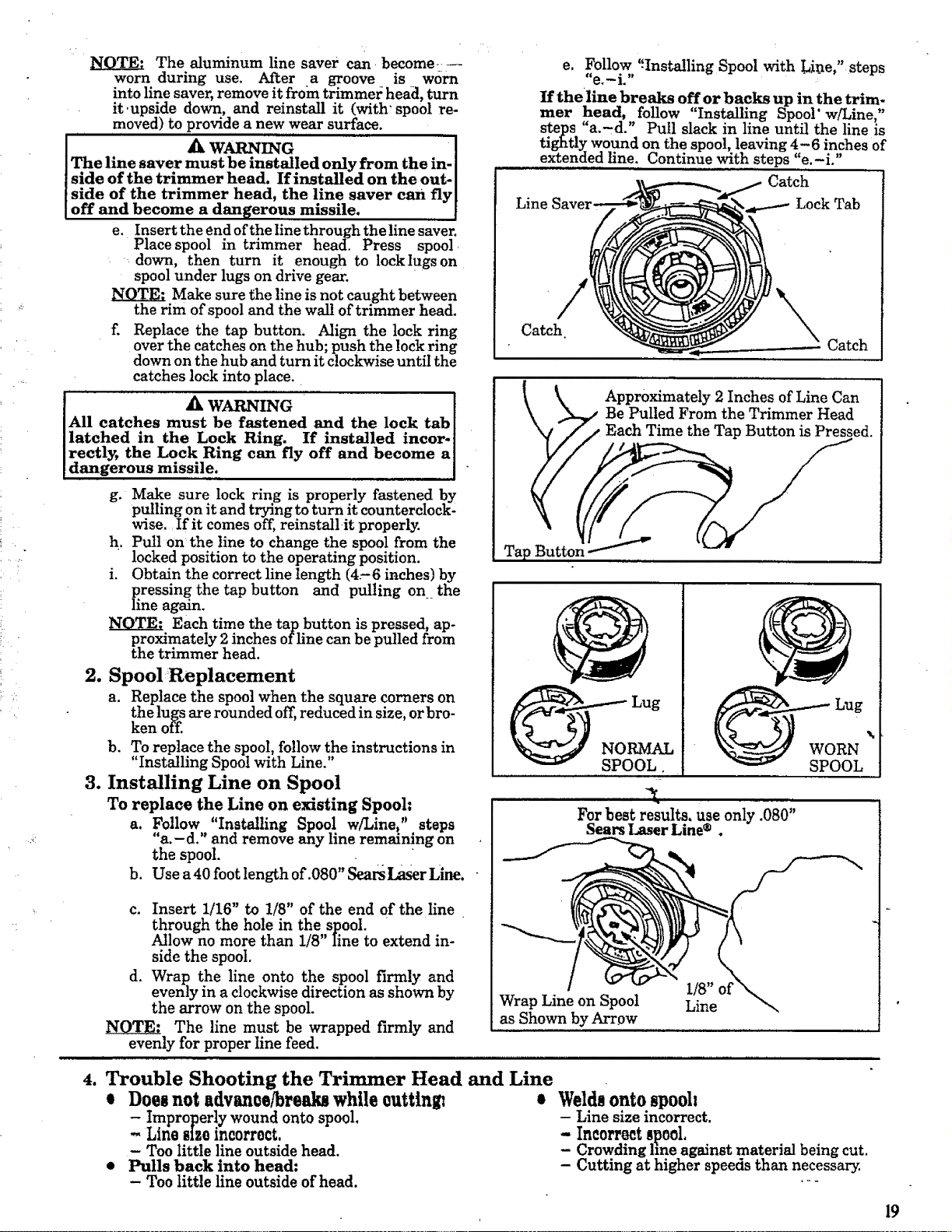
The aluminum line saver can become_-
worn during use. After a groove is worn
into line saver, remove it from trimmez: head, turn
it.upside down, and reinstall it (with" spool re-
moved) to provide a new wear surface.
I A WAJaNmG [
The line saver must be installed only from the in- I
side of the trimmer head. If installed on the out- I
side of the trimmer head, the line saver can fly[
off and become a dangerous missile. .
e. Insert the end of the line through the line saver.
Place spool in trimmer head. Press spool
down, then turn it enough to lock lugs on
spool under lugs on drive gear.
Make sure the line is not caught between
the rim of spool and the wall of trimmer head.
f. Replace the tap button. Align the lock ring
over the catches on the hub; push the lock ring
down on the hub and turn it clockwise until the
catches lock into place.
A W n'.TG [
All catches must be fastened an.d the lock tab l
latched in the Lock Ring. If Installed incor°
rectly, the Lock Ring can fly off and become a]
dangerous missile. ]
g. Make sure lock ring is properly fastened by
pulling on it and trying to turn it counterclock'
wise.: if it comes off, reinstallit properly.
h. Pull on the line to change the spool from the
locked position to the operating position.
i. Obtain the correct line length (4.-6 inches) by
pressing the tap button and pulling on the
line again.
NOTE: Each time the tap button is pressed, ap-
proximately 2 inches of line can be pulled from
the trimmer head.
2. SpoolReplacement
a. Replace the spool when the square corners on
the lugs are rounded off, reduced in size, or bro-
ken off.
b. To replace the spool, follow the instructions in
' Installing Spool with Line."
3. Installing Line on Spool
To replace the Line on existing Spool:
a, Follow "Installing Spool w/Line," steps
"a.- d." and remove any line remmmng, on
the spool.
b. Use a40 foot length of.080" Sears Laser Line.
c. Insert 1/16" to 1/8" of the end of the line
through the hole in the spool. •
Allow no more than 1/8" Iine to extend in-
side the spool.
d. Wrap the line onto the spool firmly and
evenly in a clockwise direction as shown by
the arrow on the spool.
NOTE: The llne must be wrapped firmly and
evenly for proper line feed.
e, Follow ':Installing Spool with Lin.e," steps
"e i "
If the line breaks off or backs up in the trim-
mer head, follow "Installing Snool' w/Line"
steps a.-d. Pull slack m hne until the hne is
tightly wound on the spool, leaving 4-6 inches of
extended line. Continue with steps "e.-i."
Catch
Line Lock Tab
Catch
Catch
Approximately 2 Inches of Line Can
_,/Be Pulled From the Trimmer Head
Each Time the Tap Button is Pressed.
___ _,_..m-._ Lug
Ooo .
t
For best results, use only .080"
Sears Laser Line ® .
Wrap Line on Spool
as Shown by Arrpw
1/8"
Line
4. Trouble Shooting the Trimmer Head and Line
0 Does not advan0e/breakl while euttin$ i Welds onto spooh
- Improperly wound onto spool. - Line size incorrect.
--hinesizeincorrect. - Incorrect8p0ol,
- Too littlelineoutsidehead. - Crowding lineagainstmaterialbeingcut.
• Pulls back into head: Cuttingat higherspeedsthan necessary.
- Too little line outside of head, .--
19

ii iiiii i ii i ]llllii II I IIII 1111111111
TIJIII IIIIII III I I II I
ACCESSORIES
i ii ii IIIIIINIWllllmIWIUWIIHIi Nil ii Hllm I
The following accessories are available through Sears
ITEM
In
Retail Stores, Catalog, Outlets or Service Centers.
STOCK NO.
Safety Face Shield ........... , ...................................................... 9-18613
Safety Goggles......:...... ........................................................ 9-1859
2-Cycle Engine Oil ......... ,.. .................................................... 71-30143
Spark Plug., ......... , ........................................................... 71-85854
Replacement Weed BIade... .... ................................................... 71-85735
Replacement Trimmer Head (available only through Sears Service Centers) ............... 952-701643
Replacement .080" Dia. NylonTrimmer Line
400 ft...... . .. !........ ........ .. ................. . ......................... 71-85778
-- 200 ft.. ...................................................................... 71-85608
100 ft.............................................................. • .......... 71-85771
Replacement Spool with Line ....................................................... 71-85815
Shoulder Strap Kit ............................................................... 71-85783
Spark Arrestor Kit ............ ........ ,. ,_.............................. ......... 952-701612*
Flex Shaft Lube ................................................................ 530-030102*
*Available through your SEARS SERVICE CENTER/CATAlOGUE.
I I Illlll Illllll IIIIIIIIIII III I II [ I II IIIII
NOTES
2O
iiii i ii i i ! i
CUSTOMER .RESPONSIBILITIES
i i it t i t i i i t ill i iq i
A. _._ICE SAFETY
I. Maintain the tool according to recommended pro-
cedures. Keep the blade sharp and the cutting line at the pro-
per length.
2, Never start the engine with the clutch shroud
removed. The clutch can fly apart and cause serious
injury.
3. Disconnect the spark plug before performing
maintenance except for carburetor adjustments.
4.
Make carburetor adjustments with the drive shaft hous-
ing supported to prevent the blade or trimmer line from
contacting any object. Hold the tool by hand; do not use the
shoulder strap for support.
6. Be sure blade or trimmer head stops turning when
engine idles. See "Carburetor Adjustments.'"
7:. Wear protective gloves when handling or performing
maintenance on the blade.
. Throw away blades that are bent, warped, cracked,
broken, or damaged in any other way. Replace trim-
mer head parts that are cracked, chipped, broken,
or damaged in any other way beforeusing the tool.
9. Use only .080" diameter Sears Laser Line. Never
use wire, rope, string, etc.
10. Use only genuine replacement parts as recommend-
ed by Sears.
5. Keep others away when making carburetor
adjustments.
II I I
B. _i, lg D_ $_ IJ/g_cJk'£1Ol_l
• Lubricate the Flexible Drive Shaft:
- After each ten (10) hours of operation.
- Before operating if the tool has been
stored for 90 days or longer.
When ordering flex shaft lube, See the
Accessory:List for proper part number.
A WARNV G I
If engine has just been operated, avoid touching I
the muffler. A hot muffler can cause serious[
burns. I
Lay the flexible drive shaft on a
clean surface. Avoid laying the shaft on the
floor, groun.d or on any other sttrface that
may have dirt or debris. Even after wiping
the shaft, grease residue can pick up dirt
particles that can cause damage or prema-
ture failure.
Take care to avoid injury to your
-- h_a-d_ and fingers with broken wires when
checking for damage or wiping the flexible
drive shaft. A cloth will not prevent broken
wires from puncturing or tearing your skin.
!. Remove the gear box clamp screw and the Io- I
eating screw from the gear box.
2- Remove the gear box from the tube.
3. Remove the flexible drive shaft from the tube.
4. Check flexible drive shaft for broken wires,
twists or kinks, and replace if damage is found.
5. Using a clean cloth, wipe surface of flexible
drive shaft thoroughly to remove any grease.
[ •
11.
InsPect the entire tool. Replace damaged parts. Check
for fuel leaksand make sure all fasteners are in place
and securely fastened.
;, ; .......
6. Apply a uniform coat of lube to the entire sur-
face of the flexible drive shaft.
7. Inject the remaining contents of the tube into
the top of the tube.
8. Replace flexible drive shaft in the tube.
9. Reassemble the gear box to the tube. Tighten
screws securely.
I
.!
21
ii ii i i i t ii i
iiii
c. uazaxm
, ; : ,, ........i -_:---:- follow the instructions. The basic carburetor settings _
[ AkWARNING ........ / are provided in the event they are required.
] Make_adjustmentswi'thtbedriveshaft_,:/ '_....... Turn the Low Speed Mixture Screw and the:High"
ing supported to prevent the mane or trtmmer nne. " .... -
.... I. .... . . .... ,.., ......... ,_.._.._,,^_._;[ Speed Mixture Screw clockwtse untd they stop.
itromcomactmganyoojoet.rtotometomwzmyuurnmm,[ t3_, ,.,m t,,_, th .... _,,,_ until thin, are tieht as
]do not use theoptional shoulder strap for support. [ damage to'theneedle+seatscan occur, v" *"
_IbWAIII_ING b. Turn the Low Speed Mixture and High Speed Mix-
' ture Sct:ews one full turn counterclockwise.
Keep others away when making carburetor
• :: c. Follow instructions "a. Preparation,' through "f.
adjustments. High Speed Mixture Adjustment.,
"_kWARNING
Serious injury to the operator and others can occurifthe
carburetor is not properly adjusted.:
• Poor engine performance can be a result of other
causes such as dirty air: filter, carbon build-up
on muffler outlets, etc. See "Trouble Shooting
Chart" before proceeding' with carburetor ...... :
:adjustments. ::
$ The carburetor has been carefully adjusted at the *:+
factory. However, the operator must be sure that
• : adjustments are made when any of the'conditions
occur as mentioned in "Trouble Shooting Sugges-
tions" below.
• Very small adjustments can affect engine perfor-
mance. It is important to turn the screw a very small
amount _per adjustment and test performance before
making further adjustments. Each adjustment should
be no more than the width oflhe slot in the adjusting
screws.
• This is a complicated task. It is important to follow
instructions in sequence as indicated.
1. TROUBLE SHOOTING SUGGESTIONS
-- Engine will not continue to run at idle position.
See "b" Idle Speed Adjustment" and "e. Low
Speed Mixture Adjustment:'
_ Blade or Trimmer Head continues to spin when
the engine idles. See"b. Idle Speed Adjustment"
and "d. Deceleration Check:'
-- Engine dies or hesitates when it should accelerate.
See "c. Acceleration Check"
-- Ia3ss ofcutting power which cannot be corrected
by cleaning the air f'dter. See "f. High Speed Mix-
ture Adjustment"
-- Engine does not return to idle from full throttle
within 2 seconds, See "d, Deceleration Check"
--Engine will not run. See "Trouble Shooting
Chart" Then, if'the carburetor requires adjust-.
ment, begin with"2. Basic Carburetor Settings:'
&WAaSISG ......I
The Blade or trimmer line will be spinning-dii-l:irig
most of this procedure. Wearyour protective equipment
.__d°bse_e all safety instru_ction.s. .....
-+2.BMIIC CARB_TOR |l_Oll
NOTE: In most cases, your engine can be made to
run properly with minor carburetor adjusunents.
l_fer to "Trouble Shooting Suggestions" in the left
column for the condition you are experiencingand
a. PREPARATION
i.) Use a fresh fuel mix. See "Fueling Your Engine:' +
2. iMake sure line extends tOthe length allowed by line
limiter to provide'correct load on engine.
3.)Start the engine. Cut grass for 3 minutes to warm
engine. The engine must be at operating temper-
ature before carbt_retor adjustments can be per-
formed correctly ,
4. )Stop engine and remove air filter by pulling it out
with your fingers. Refer to "Specifications" for
location.
b. IDLE SPEED ADJTtJSTMENT
l.)Ailow engine to idle.
2.)Adjust Idle - Speed Screw until the:: engine
continues to run •without stalling and .__
without the trimmer head moving.
-- Turnsc-_ clockwise to increase engine speed +
if the engine stalls or dies.
-- Turn screw counterclockwise to slow engine
down and/or to keep blade or trimmer head
from turning.
3.)Follow instructions]n "c. Acceleration Check'"
and "d. Deceleration Check"
4.)N 9 furthei" adjustments are necessary if the
trimmer head does not turn at idle speed and
L if performance is satisfactory.
A WAmCmG
Recheck idle speed after each adjustment. The blade or
trimmer head must not turn at idle speed to avoid serious
injury to the operator and others.
€. ACCELERATION CHECK
i.)Allow engine to idle.
2,)$qu©cz¢ Trisger fully
a. If performance hsatisfactory, proceed to "d.
Deceleration Check."
b. If the engine does not accelerate smoothly,
tum_e _LowSpeed MixtureScrew counter-
clockwise a small amount (no more, thanthe
width of the slot in the adjusting screw).
3.)Repeat step "2.)" until smooth acceleration is
obtained,
NOTE: It may be necessary to repeat "b. Idle
Speed Adjustment" through "'c. Acceleration
Check :' to obtain correct adjustments.
<) Follow instructions in "d. Deceleration Check .'"
i
d. DECELERATION CHECK
1.) Allow engine to idle, then squeeze Throttle Trig-
ger fully.
2:)Allow engine to run at full speed for about 1
second.
3.iRelease the Throttle Trigger to the idle position
and listen to the deceleration of the engine. It must
return to idle smoothly and within I to 2 seconds.
a. If performance is satisfactory,-proceed to
step "4.)"
b. If the engine slowly or erratically returns to
idle or idles erratically, repeat"b. Idle Speed
Adjustment" or continue through Low Speed
Mixture and High Speed Mixture Adjustments
4.)Set the _ Speed Mixture Screw at the mid--
point between the two positions.
_.:!: : = 5:)Follow instructions in "c. Acceleration Check"
• and "d, Deceleration Check"
f. HIGH SPEED MIXTURE ADJUSTMENT
[CAUTION:] Do not operate engine at full
throttle for prolonged periods while making high
: : : speed adjustments as damage to the engine
can occur.
1.) Support the drive shaft housing so the trimmer
line is offthe ground and will not make contact
with any object.
2.)Al!ow engine to idle, then squeeze Throttle Trig-
ger fully.
NOTE: Perform steps "3.)" through "5.),'
:at full throttle. ....... .
3.) Tum High speed, Mixture Screw veby slowly
clockwise until engine speed is reduced.
4, )'i_Jm--Hig--h-S_ed Mixiure Screw vdry _Io_iv---
counterclockwise. Stop when the engine begins
to run roughly.
5.) Turn the screw slowly the minimum amount
clockwise until the engine runs smoothly.
6.) Follow instructions in "c. Acceleration Check"
and "d, Deceleration Check:' i
!CAUTION:] If the engine does not operate
accordLng to these instructions after repeating
the adjusting steps, do not use the tool. Take
' it to your Sears Service Center.
to obtain proper deceleration.
4. )Recheck idle speed.
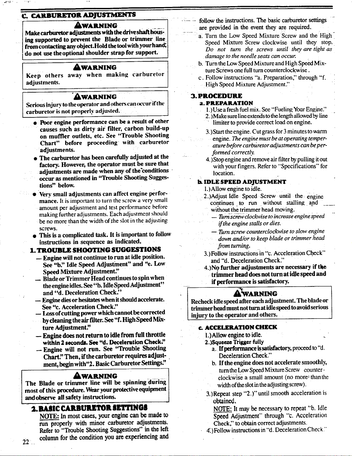
HIGH SPEED MIXTURE
IDLE SPEED AIR
ADJUSTMENT FILTER
SCREW COVER
I
I
I.)Allow engine to idle.
2, Turn the Low Speed Mixture Screw slowly ,I
..... Lclockwise until thespeed starts todrop. - /
Note this position.
3:)Turn the Low Speed Mixture Screw counter------
clockwise until the speed increases and then
starts to drop again. Note this position.
i1 i it II ] ]
D.. STARTER ROPE ...................................................
&t tNGra •
Never start the engine with the clutch shroud removed.
The clutch will fly apart and cause serious injury.
Ak WARNING
Do not remove the retaining tab and screw" to remove
pulley. The spring beneath the pulley is under teusion
and can fly out causing serious injury, ffany part of the
put housingassemblyisdamagedotherthantherope,
do not use the tool. Take it to your Sears Service Center.
I. Disconnect Spark Plug Wire. ,................
2. Remove the Screw and Nut in the Throttle Trigger
Housing.HotdtheThrottleTrigger away from Drivel
Shaft Housing and remove Throttle Cable from i
Trigger. Pull Cable out of Foam Grip :_
tunnel.
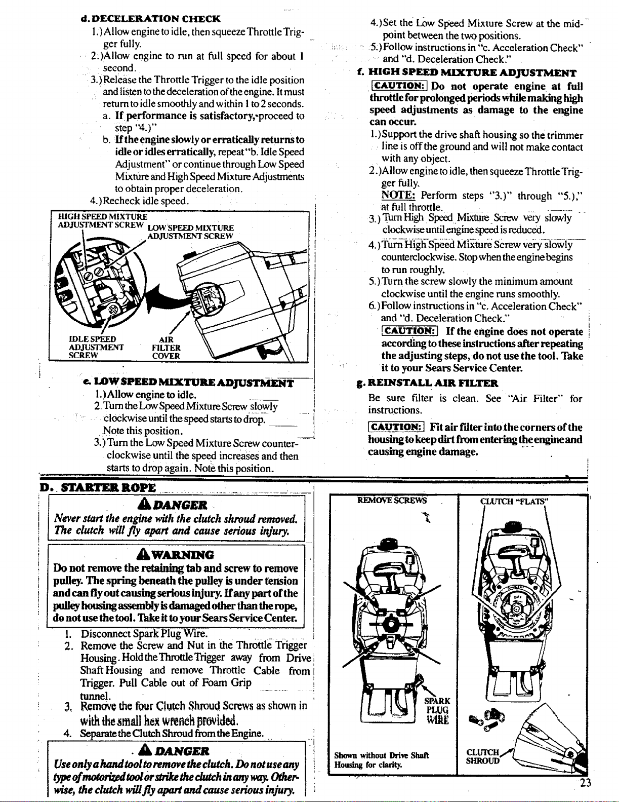
3, _rn_€ the fourClutch Shroud Screws_ shown in
withthesm ll wrenehprovided,
4. Separate theClutch Shroud fromthe Engine, L.
•& O Gml , [ !
Use only a hand tool to remove the clutch, Do not use any
type of motorized tool or strike the clutch in any way. Other-
wise, the clutch wiU fly apart and cause serious injury.
g. REINSTALL AIR FILTER
Be sure filter is clean. See
instructions.
"Air Filter" for
]CAUTION: ] Fit air f'dter into the corners ofthe
housing to keep dirt from entering the engine and
causing engine damage.
I
f
H..... . L_ ' ......
REMOVESCREWS € "FLATS"
:hown without Drive Shaft
HousLngfor clarity.
7
SHROUD_
| iii
23
5. Hold the "Flats" of the Clutch with an adjustable
wrench as shown in Figures and remove the Nut
counterclockwise with a 9/16" socket wrench.
NOTE: Clutch will slide offthe crankshaft intact. Do
not disassemble clutch.
6. Remove the Beveled Washer, Clutch and Large Flat
Washer.
7. Remove the Pulley Housing from the Engine. •
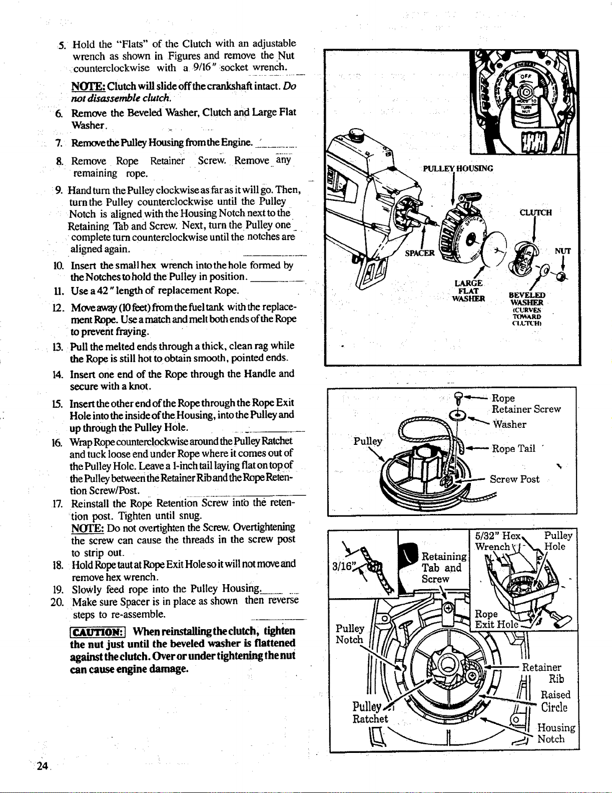
8. Remove Rope Retainer Screw. Remove any
remaining rope.
:9.
4
10.
11.
12.
3,
I4.
Hand turn the Pulley clockwise asfar as it will go. Then,
turn the Pulley counterclockwise until the Pulley
Notch is aligned with the Housing Notch next to the
Retaining Tab and Screw. Next, turn the Pulley one
complete turn counterclockwise until the notches are
aligned again.
Insert the smallhex wrench into the hole formed by
the Notches to hold the Pulley in position.
Use a 42 "length of replacement Rope.
Move away (10feet) from the fuel tank with the replace-
ment Rope. Use a match and melt both ends of the Rope
to prevent fraying.
Pull the melted ends through a thick, clean rag while
the Rope is still hot to obtain smooth, pointed ends.
Insert one end of the Rope through the Handle and
secure with a knot.
15. Insert the other end of the Rope through the Rope Exit
Hole into the inside of the Housing, into the Pulley and
up through the Pulley Hole.
16. Wrap Rope counterclockwise around the Pulley Ratchet
and tuck loose end under Rope where it comes out of
the Pulley Hole. Leave a 1-inch tail laying flat on top of
the Pulley between the Retainer Rib and the Rope Reten-
tion Screw/Post.
17. Reinstall the Rope Retention Screw into the reten-
tion post. Tighten until snug.
NOTE: Do not overtighten the Screw. Overtightening
the screw can cause the threads in the screw post
to strip out.
18. ltold Rope taut at Rope Exit Hole so it will not move and
remove hex wrench.
19. Slowly feed rope into the Pulley Housing__ .....
20. Make sure Spacer is in place as shown then reverse
steps to re-assemble.
ICAUTION:t When reinstallingtheclutch, tighten
the nut just until the beveled washer is flattened
against the clutch. Over or under tightening lhenut
can cause engine damage.
PULLEY HOUSING
CLUTCH
_"---- Rope
Retainer Screw
Pulley
Washer
I"*---Rope Tail "
Screw Post
3110
Retaining
Tab and
Screw
5/32" Hex_
Rope
ExitHole_:
Pulley
Pulloy.
Ratchet
Retainer
Rib
Raised
Circle
Housing
Notch
_ i i i i ii
_E. AIIt FIL11_
A dirty air filter decreases the life and
performance of the engine and may increase fuel
consumption and harmful emissions.
1. Clean the Air Filter:
• Always after 5 tanks of fuel or 5 hours of
operation, whichever is less.
• Mor e frequently, in dusty conditions.
a. Loosen _hetwo screwson theairfiltercover
enough to remove thecoverfrom engine,
b. Remove the airfilterfrom the cover,
c. Wash filterinsoap and water.
d. Squeeze filterdry and replaceincover.
• C['-C'_UT_ Make sure the air filter is fitted
into the corners of the cover to keep dust
from entering the engine and causing en-
gine damage. ....
If replacing the air filter, see the
Accessory List for proper part number.
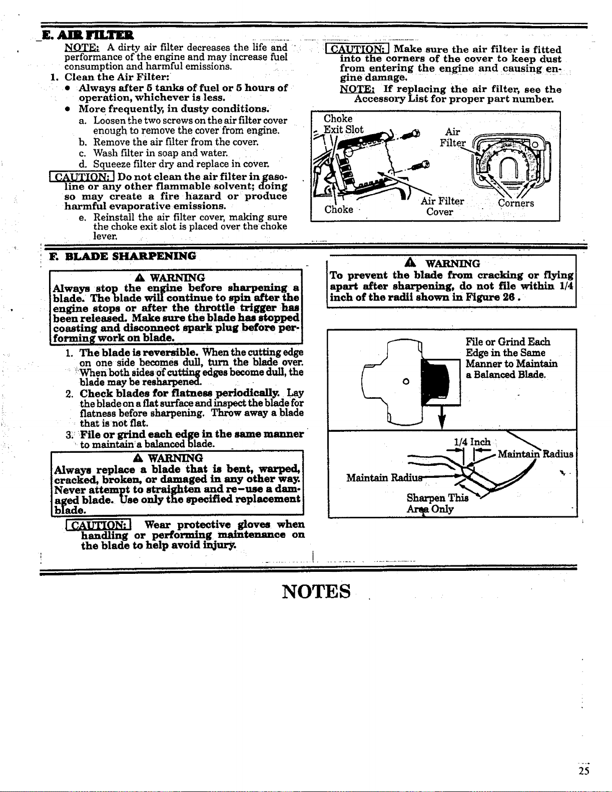
Choke
._ Air
Filter
so may create a fire hazard or produce
harmful evaporative emissions.
e. Reinstall the air filter cover, making sure
the choke exit slot is placed over the choke
lever. :
i IF. BLADE SHARPEIqlI_G
A .....
Always stop the engine before sharpening a
blade: The blade will continue to spin after the
engine stops or after the throttle trigger has
been released. Make sure the blade has stopped
coasting and disconnect spark plug before per-
forming work on blade. ..........
I. The blade is reversible, When the cutting edge
on one side becomes dull, turn the blade over.
...._When both sides!Of cutting edges become dull, the
blade may be resharpenroened,. -
2. Check blades for flatness periodically. Lay
the blade on a flat surface and inspect the blade for
flatness before shArperdng. Throw away a blade
that is not fiat.
3/File or grind each edge in the same manner
'to maintain_abalancedblade.
A WARNING " '
Always replace a blade that is bent, warped,
cracked, broken, or damaged in any other wa3_
Never attempt to straighten and re-tree a dam-
aged blade. Use only tee specified replacement
blade.
AirFilter Corners
Cover
11 _ . _ IIII III
A WAR G ]
To prevent the blade from cracking or flying[
apart after sharpening, do not file within 1/4[
inch of the radii shown in Figure 26. I
File or Grind Each
Edge in the Same
Manner to Maintain
a BalancedBlade.
1/4Inch i f_._
Radi_
Maintain
Ar On]y
Wear protective gloves when
handling or performing maintenance on
the blade to help avoid injury.
.............. ................................
H u, t,um
lull HI u II IHII III I
, ,, ,utr,tl
NOTES
T..
25
i i . i i i i, HIIIIIIIII I
Immediately prepare your unit for storage at the end of the
season or if it witl not be used for 30 days or more.
WARNING:
ALLOW THE ENGINE TO COOL, AND SE-
CURE THE UNIT BEFORE STORING OR
TRANSPORTING IT IN A VEHICLE.
STORE UNIT AND FUEL IN AN AREA
WHERE FUEL VAPORS CANNOT REACH
SPARKS OR OPEN FLAMES FROM WA-
TER HEATERS, ELECTRIC MOTORS OR
SWITCHES, FURNACES, ETC.
STORE UNIT WITH ALL GUARDS IN
P LACE. POSITION SO THAT ANY SHARP
OBJECT SUCH AS BLADES CANNOT
ACCIDENTLY CAUSE INJURY TO PASS-
ERS BY.
STORE THE UNIT OUT OF THE REACH
OFCHILDREN.
GAS TRIMMER/BRUSHCUTTER STORAGE
INSTRUCTIONS
if your tdmmedbrushcutter is to be stored for a period of
time, clean it thoroughly prior to storage. Remove any
dirt, sawdust, leaves, oil, grease, etc. Store in aclean dry
area.
0 °
Clean theentire unit.
Clean air filter. Refer to ,Customer Responsibilities".
Open the line head assembly and clean any dirt, grass or
debris that has collected. Inspect the cutting line, if old
(chalky look and sticky to the touch), remove and dis-
card. Install fresh new line the next time product is to be
used.
Lightly oil external metal surfaces to prevent rust from
forming.
- AUTION: Wear protective gloves when
handling blade. The blade is sharp and
can cut you even when it is not moving.
If your unit is equipped with a blade, remove it from the
unit. Refer to "Assembly". Apply a coating of oil to the
entire surface of the blade and wrap it in heavy paper,
cloth, or plastic. Also apply a light coat of oilto gear hous-
ing threads, then tighten blade nut securely for storage.
Reassemble all loose parts, being sure that all handles
andgu=rdsareinp!a_eandaresecurelyfastened,Ra-
pla0eanydamagedparts.
ENGINE
Never use engine orcarburetor cleaner products in the fuel
tank or permanent damage may occur to fuel system com-
ponents,
Follow these instructions:
a. Drain the fuel from the unit into an approved
fuel container.
b. Drain the fuel lines and carburetor by starting
the engine and letting it run until it stops.
c. Allow the engine to cool before storage.
IMPORTANT: It is important to prevent gum deposits from'
forming in essential fuel system parts such as the carbure-
tor, fuel filter, fuel I{ne or tank during storage. Also, experi-
ence indicates that alcohol blended fuels, those that use
ethanol or methanol (called gasohol or oxygenated fuel),
can attract moisture and form acidic gas which will damage
your engine. To avoid engine problems, the fuel =system
should be emptied before storage of 30 days or longer.
NOTE: Fuel stabilizer is an acceptable alternative in mini-
mizing the formation of fuel gum deposits during storage.
Add stabilizer to the gasoline in the fuel tank or fuel storage
container. Always follow the mix instructions found on stabi-
lizer container. Run engine at least 5 minutes after adding
stabilizer to allow the stabilizer to reach the carburetor.
NOTE." Craftsman 40:1 2-cycle engine oil is specially
blended with fuel stabilizers. If you do not use this SEARS
oil,you can add a fuel stabilizer (such as Craftsman #33500)
to your fuel tank.
• Remove spark plug and pour I teaspoon of 40:1 oil mix
through the spark plug opening. ,Slowly pul! the starter
rope 8 to 10 times to distribute oil to inner engine sur-
faces.
• Replace spark plug with a new one of the recommended
type and heat range, Refer to "Product Specifications".
• Clean air filter. Refer to."Customer Respo_n_sibilities".
• Reinstall all covers_nd hardware removed for access;
tighten al! screws arrcl fasteners.
• Check entire unit for loose screws, nuts, and bolts. Re-
place any damaged, broken, or worn parts.
• Use fresh fuel having the proper gasoline to oil ratio at the
beginning of the next season.
OTHER
• Do not store gasoline from one season to another.
• Replace your gasoline can ifyour can starts to rust. Rust
and/or dirt in your fuel system will cause problems.
• Store your unit in a welt ventilated area and covered, if
possible, to prevent dust and dirt accumulation. Do not
cover with plastic. Plastic cannot breathe and will induce
condensationand eventualrustorcorms!on.
[M.P_QJ_T._!_ Never cover unit while engine and exhdust
areasarestillwarm,
26

TROUBLE SHOOTING
SYMPTOM
start or will run
only for a few
seconds after
Starting.
Engine will not
idle properly.
Engine will not
accelerate,lacks
power, or dies
under a load.
Engine
smokes
excessively.
Engine runs hot.
Cutting Head stops
under a load or
does not turn
when engine is
accelerated: :
i i,J JL
Line doesnot
advance or breaks
while cutting. _ _ :
i,,.
Line welds on spool.
Line releases
continuously.
Line usage is
excesslve.
Line pulls back
into head.
.
4.
5.
6.
1.
CAUSE _ •
II, II
1. Fuel tank empty.
2. Engine flooded.
Spark p!ug not firing.
Fuel not reachingcarburetor.
Carburetorrequiresadjustment.
None oftheabove.
Carburetor requires adjustment
2. None of the aboVe.
1. Air filter dirty,
2, Spark plug fouled.
3. Carburetor requires adjustment,
4.
Muffler outlets plugged,
.
5.
6.
| ,,,,,,,,,,
1.
2.
REMEDY
,, .,, ==
1, Fill tank with correct fue! mixture
2, See "Starting Instructions."
3. Install new plug/check ignition system,
Clean fuel filter; inspect fue! line.
See "Carburetor Adjustments."
Contact yovr Sears Service Center/Dept,
See "Carburetor Adjustments,"
Contact your Sears Service Center/Dept,
, ,,..,., ,,,,, ......... • ,....
1. Clean'or replace air filter.
2. Clean or replace spark plug and re-gap.
3. See "Carburetor Adjustments."
4. Contact your Sears Service Center/Dept.
5_
........ , ....... ,,,,, ,,, ....
1. Air filter dirty.
2. Fuel mixture incorrect.
3, Carburetor requires adjustment.
.
2.
3.
4.
.
None of the above. 5. i Contact y0ur Sears Service Center/Dept,
Fuel mixture incorrect. 1.
Carburetor requires :adjustment. 2.
Spark plug incorrect. 3.
None of the above. 4.
.................... p ....
Drive shaft broken. 1,
2. Drive shaft not engaged.
,, ,, i,,,i,,,,,,,,,,,,,,,,,,,,i,,,
i. Line improperlyroutedin head.
2. Line improperlywound onto spool.
3. Line sizeincorrect.
4. Too little line outside head.
5. Dirt accumulated on cover cut-outs.
...... ,.,,, ill IIMH
1. Line size incorrect.
2. Crowding lineagainstmaterialbeing cut.
3. Cuttingat higherspeedthan necessary.
, = ..................... , ,,,m
I. Tap Button engaged.
2. Tap buttonknocked out ofhub.
..............................._ ,,L
I. Line sizeincorrect.
Cuttingat high speed around hard objects.
Crowding lineagainstmaterialbeingcut.
Too littlelineoutsideofhead.
, i ............
1. Clean or replace air filter.
2. See "Fueling Your Unit."
3. See "Carburetor Adjustments,"
See "Fueling Your Unit."
See "Carburetor Adjustments."
Replace with correct plug.
Contact your Sears Service Center/Dept.
i,,,,u,,,,,,
Replace drive shaft.
2.. See "Assembly".
.
3,
, ,,± i1,,i,,1,
@
i. Remove coven Check linerouting.
2. Rewind linetightlyand evenly.
3. Use only.080"(2ram)diameterSearsLaser
Line.
4. Remove cover.Pull4,'oflineto outside._
5. Clean covercut-outs.
,HH .... '"'........
1. Use only.080"(2ram)diameterSearsLaser
Line. -_
2. Cut witht_ of line.
3. Reduce cutting speed.
1. Remove and clean Tap Button.'- -
2. See "Installing Spool w/Line."
1, Use only .080" (2mm) diameter Sears Laser
Line.
2. Reduce speed around hard objects.
3. Cut with tipofline.
• Remove cover.Pull4" (10cm) oflineto
outside.
27

t dd tim, t,, t ,tl , ttmt ,,,,,, ,uoit ,,,it I __i_,,,,................it , t
t ,,, ,,,, ....................................
III illliililllllllllllllllllllllllil . .mm i...........
LUBRICATION
ADJUSTMENTS Engine ........................................................................... 11
Handlebar ............................................................................. 7 Flexible Drive Shaft ...................................................... 2I
Carburetor .......................................................................... 22 MAINTENANCE
IA ne Advance ..................................... _............................... 17
Module Air Gap ................................................................... 2
Spark Plug Gap .................................................................... 2
Shoulder Strap .................................................................... 10
Throttle Cable ...................................................................... 7
AIR FILTER ............................................................................. 25
ASSEM B i,¥
Blade .................................................................................... 9
Clamp, Shoulder Strap ....................................................... 10
Handlebar ............................................................................. 7
Preparation ........................................................................... 6
Shield
Line Trimmer ............... _.................................................... 8
Air Filter .................. _.................................................... 25
Blade, Weed .................................................................. 25
Carburetor ..................................................................... 22
Flexible Drive Shaft ...................................................... 21
Safety ............................................................................ 21
Starter Rope...:.............................................................:..........23
Triromer Head ............................................................... 19
Trouble Shooting Chart ................................................. 26
MODULE AIR GAP.L ...... :.................................................. 2
OIL, ENGINE
Ratio to Gasoline ........................................................... I 1
Types to Use; not_o Use ............................................... I 1
OPERATION
Weed Blade ....................................................................... 9
Shoulder Strap ......................................................... ........... 10
Throttle Cable ...................................................................... 7
Trimmer Head ...................................................................... 8
Weed Blade .......................................................................... 9
!1LADE, WEED
Cutting Methods ................................................................. 14
Guard Against Blade Thrust .............................................. 15
Maimcnaace ....................................................................... 25
Safety ................................................................................. 2 I
Sharpening ......................................................................... 25
CARBURETOR ADJUSTMENTS ........................................ 22
CARTON CONTENTS ............................................................. 5
COLD ENGINE STARTING .................................................. 12
Advancing the Line ....................................................... 17
Mowing ......................................................................... 18
Pre-Operation Cheeks ................... ;............................... 12
Position ......................................................................... 10
Safety
Blade .......................................................................... 15
Line Tdmmer ............................................................. 17
Scalping ........................................................................ 18
Starting the Engine ........................................................ 12
Speed ............................................................................. 13
Stopping the Engine ...................................................... 12
Sweeping ....................................................................... 18
Trimming ...................................................................... 18
Weed Btade ................................................................... 16
CONTROI,S ............................................................................... 2
CUTTING METHODS
Weed Blade ........................................................................ 16
Line Trimmer ..................................................................... 18
DRIVE SHAFT HOUSING ASSEMBLY ................................ 6
ENGINE
Air Filter ............................................................................. 25
Carburetor .......................................................................... 22
Controls ................................................................................ 2
Fuel Mixture ....................................................................... 1i
Starter Rope ....................................................................... 23
Starting Instructions ........................................................... !2
Storage ................................................................................. 4
Trouble Shooting ................................................................ 26
ENGINE OIL
Ratio to Gasoline ................................................................ I I
Types to Use; not to Use .................................................... 1l
FILTER, AIR ............................................................................ 25
FI.EXIBI,E DRIVE SHAFT LUBRICATION ...................... 21
FUEl,
GasolinetOil Mixture ......................................................... 11
Mixing Fuel ........................................................................ 11
Pouring Fuel ....................................................................... 1!
Safety ................................................................................. 11
Storage ............................................................................... 11
GASOLINE
Ratio to Oil ......................................................................... 11
Type to Use; not to Use...................................................... 11
IDLE SPEED ADJUSTMENT ............................................... 22
LINE
Advance ............................................................................. 1?
Breaking ............................................................................. 20
Length
Operation ......................................................................... 19
To Cut as Replacement ................................................... 20
Replacement ....................................................................... 19
I(c\viudilt_ un Sl_t_l ........................................................... 20
Routing hi Head ................................................................. 19
Safety ................................................................................. 19
Size to Use ......................................................................... I9
"l'rt_ubl¢Shta_ting ................................................................ 20
Wekling Ohio Spool ............................................................ 20
PARTS LIST ....................................................................... 27
PRE-OPERATION CHECKS ........................................... 12
PREWOUND SPOOLS ..._................................................. t 9
REPAIR PARTS LIST ....................................................... 27 -
SAFETY INSTRUCTIONS, WARNINGS .................. 3 & 4
SHIELD
Line Trimmer Assembly ................................................. 8
Blade Assembly .............................................................. 9
SHOULDER STRAP CLAMP ASSEMBLY ................... I0
SHOULDER STRAP ......................................................... 10
SPARK PLUG GAP ............................................................. 2
SPARK ARRESTOR .................................... _................. w.,.5
SPECIFICATIONS .............................................................. 2
SPOOL
Installation ............ ........................................................ 19
Maintenance..._ ............................................................ 19
Prewound ...... ..?:............................................................ 19
Rewinding ..................................................................... 20
STARTER ROPE REPLACEMENT ............................... 23
STARTING INSTRUCTIONS .......................................... t2
STORAGE ............................................................................. 4
THROTTLE CABLE ASSEMBLY .................................... 7
TRIMMER HEAD
Assembly ....................................................................... .8
Line Routing ................................................................ 19
Maintenance .................................................................. 19
Removal ........................................................................ 19
Safety ............................................................................ 17
Shield .............................................................................. 8
TROUBLE SHOOTING CHART ................................. 26
USING YOUR TOOL AS A WEED CUTTER ............... 14
USING YOUR TOOL AS A LINE TRIMMER .............. t6
WARM ENGINE STARTING ........................................... 12
WARM ENGINE STARTING AFTER RUNNING
OUT OF FUEL .................................... . ....................... 12
WARNINGS AND SAFETY INSTRUCTIONS ......... 3 & 4
WARRANTY ........................................................................2
WEED BLADE ASSEMBLY .............................................. 9
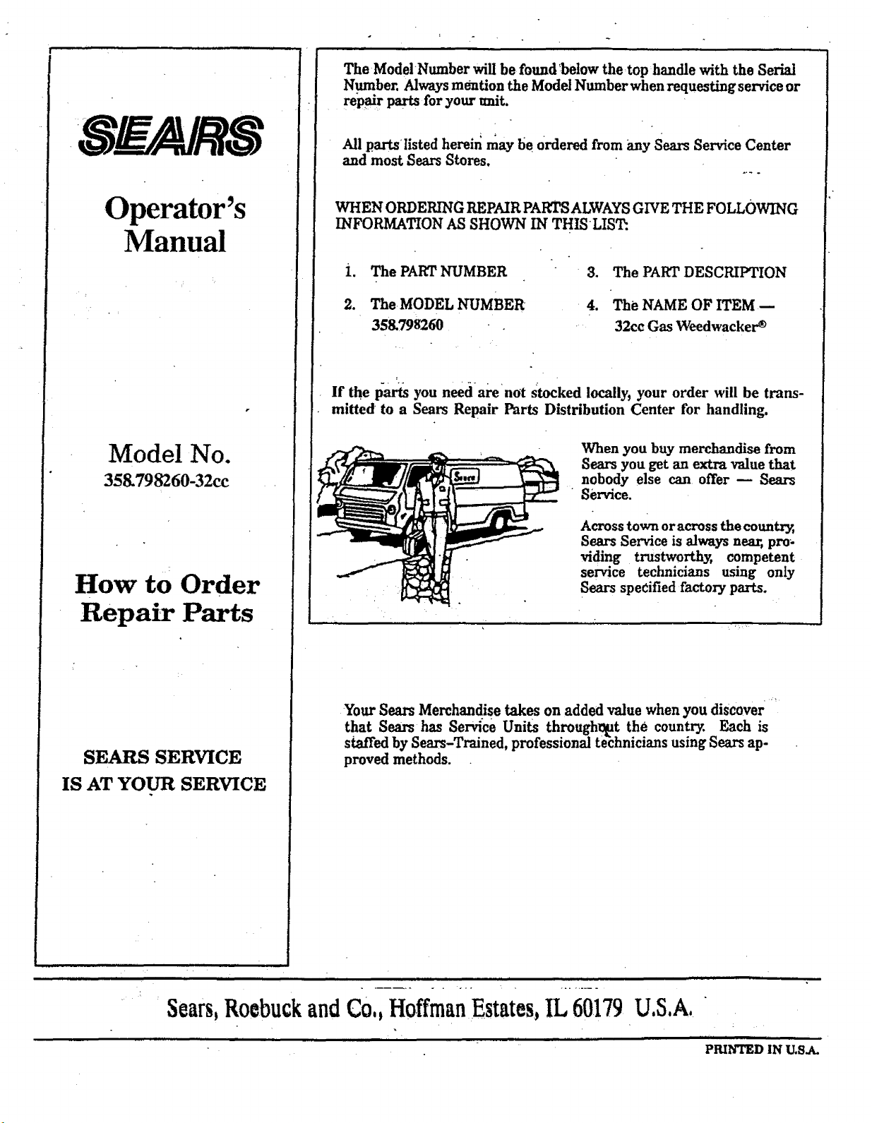
Operator's
Manual
Model No.
358.798260-32cc
How to Order
Repa_ Parts
SEARS SERVICE
IS AT YOUR SERVICE
The ModelNumber will be found below the top handle with the Serial
Number. Always mention the Model Number when requesting service or
re'pal"r parts for your trait.
All parts listed herein may be Ordered from any Sears Service Center
and most Sears Stores.
WHEN ORDERING REPAIR PARTS ALWAYS GIVE THE FOLLOWING
INFORMATION AS SHOWN IN THISLIST:
i. The PART NUMBER 3. The PART DESCRIPTION
2. The MODEL I/UMBER 4. The NAME OF ITEM --
358.798260 - 32cc Gas Weedwacker _
If the parts you need are not Stocked locally, your order will be trans-
mitted to a Sears Repair Parts Distribution Center for handling.
When you buy merchandise from
Sears you get an extra value that
nobody else can offer k Sears
Service.
Across town or across the country,
Sears Service is always near,, pro-
riding trustworthy, competent
service technicians using only
Sears specified factory parts.
Your Sears Merchandise takes on added value when you discover ....
that Sears has Service Units through_t the country. Each is
staffed by Sears-Trained, professional technicians using Sears ap-
proved methods.
Sears,RoebuckandCo,,HoffmanEstates,1L60179U.S,A,
r ,llll ................ i liHll i r. i ,j
PRINTED IN U.S.A.
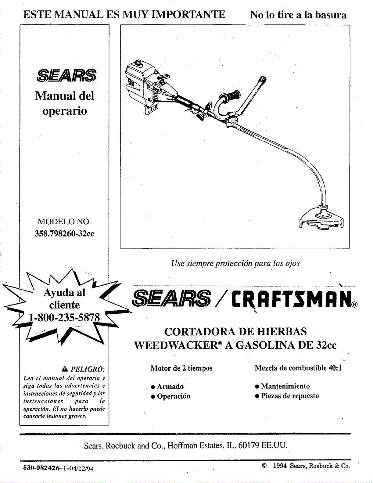
ESTE MANUAL ES MUY IMPORTANTE
No lo tire a la basura
Manual del
operario
MODELO NO.
358.798260-32cc
Ax PELIGRO:
Lea el manual del operario y
siga todas tas advertencias e
instrucciones de seguridad y las
instrucciones para ta
operacidn. El no hacerto puede
causarle lesiones graves.
Use siempre protecci6n para los ojos
SF_/AJ S/ gRRi:TSMRN®
CORTADORA DE HIERBAS
WEEDWACKER _ A GASOLiNA DE 32cc
Motor de 2 tiempos
• Armado
• Operacidn
Mezcla de combustible 40: l
• Mantenimiento
• Piezas de repuesto
Ill _ FII............................ I II II I ...............................................
Sea?s, Roebuck and Co., Hoffman Estates, IL. 60179 EE.UU.
I I.IIIl.ll I I ||.llllll I III lllllllll IIIIllullll..llll
© 1994 Sears,Roebuck & Co.
530-082426-1 _)4112/94 --

_11111 ' " . i • • • •• •1 • ' i iJi i 1
GARANTIA L1MiTADA DE DOS ANOS PARA LA CORTADORA DE HIERBAS "WEEDWACKER TM''CRAFTSMAN
PoT dos afios desde la fecha de la compra, si esta weedwacker TM es mantenida, lubricada y afinada de acuerdo COnlas instrucciones para
la operacidn y el mantenimiento contenidos en el manual del operario, Sears reparar_, libre de cargo cualquier defecto en materiales o
mano de obra.
Esta garantfa excluye la Ifnea de nylon, la bujfa y el filtro de aire que son piezas reemplazables y se gastan durante el uso normal.
Si esta Weedwacker TM es empleada para usos comerciales o para alquiler, esta garantfa no se aplica.
EL SERVICIO DE GARANTIA ESTA DISPONIBLE PONIENDOSE EN CONTACTO CON EL CENTRO O DEPARTAMENTO DE
SERVICIO SEARS MAS CERCANO ENLOS ESTADOS UNIDOS. Estagarantfa se aplica solamente mientras este producto est,'i en
uso cn los Estados Unidos.
Esta garantfa tc da a ustcd dcrcclaos legalcs especfficos y usted puede tenet otros derechos que varfan de estado a estado.
SEARS, ROEBUCK AND COJDEPT, D/817WA, HOFFMAN ESTATES, IL 60179 EE.UU.
LISTA DE CONTENIDO
ADVERTENCIAS E INSTRUCCIONES
PARA LA SEGURIDAD ...................................................... 3
CONOZCA SU IIERRAMIENTA ............................................... 5
ARMADO ....................................................................................... 6
CARGANDO COMBUSTIBLE A SU MOTOR ........................ l I
ARRANCANDO SU MOTOR ..................................................... 12
USANDO SU CORTADORA DE MATORRALES .................. 14
USANDO SU CORTADORA
COMO CORTADORA DE LINEA ..................................... I6
ACCESORIOS ;....: .............. :...:..:.,: .............................................. 20
RESPONSABILIDADES DEL OPERARIO ............................. 2 I
INDICE .......................................................................................... 31 .....
ESPECIFICACIONES
TIPODE MOTOR 2 tiemLr,_s,enfriadopoTaire
En vacfo: 2800- 3200
Si CRONIZAClON...... A .cc hi p;i---
DEL ENCENDIDO No ajustable ....
CARBURADOR Diafragma. Tnd,'t_las posicinnes con
surtidores de mezcla de combustible
OT R regulables
"APAGADO"DEL M O Bot6n para empujar _ •
ARRANCADOR Recnmllado automlitico
SILENCIADOK Limitador de temperatura (sin
parachispiLs;yea NOTA en la pfigina6)
EMBRAGUE Centfffug0 ...............
TANOUEDECOMBUSTIBLE " 17oz. Ifqui_ .....
LARGO DEL _E 5 I"(129,5 cm) ,. ..........
BUJIA 71-85854 (CJ- lff)
ABERTURA DE LA BUJIA 0.025"
ABERTURA DEL 0.0 t010.014
MODULO DE AIRE
LUBRICACIO N ................... Mezc!:t t!e g_ts_?litlay ace|re at 40:1
)
LINEAt ARA EL CORTE Seat_ !_lser Li,_e",difimetro 0.080"
HOJA Hoja pat hierbas de 4 puntos, 8"
NOTAt LASERLINE:" ES UNA MARCADE FAItRICA
REGISTRADA DE WHITE CONSOIJDATED INDUSTRIES, INC.
FAltRICADA 8AJO [ !NA 0 MAS DE I.AS SIGUIF.NT[:S PATFNTt:S U, S,: 4JB5,912:
4.1|52,78_: 4. I 12.653:4.1 hi ,_2o: 4,167.812:4.183,138: ,4.t 1_0,833:4.211,0(M: 4.286.675:
4.362.074:4.45 t.983; 4,798,185; 4,823A65; 4.841.929: 4.940.028: 5.020.223: y D324,051.
2 ESTAN PENI)I|'NTt-S OTRAS PA'F|:NTF.S U.S. Y DEL EXTERIOR•
Asa en "T" de la cuerda
para arrancar _r!l'_ Correa para el hombro '
lnterr uptoi_'_t_',,_embrague/ /9 "
" .-/_'__ Jk _// Manubr_o
/_"_spuma G_altil-lodei_ Etiqueta de seguridad
Ntimero de Serie e X_ _/ _. • "_'K
instrucdones para arrancar _-_7_:_ E_ud ° _
/ ___/___ ..- met_ilico - "I1
•
Tapa de combustible de la linea la cortadora
/
N_ Hoia para hier
con 4 dientes
Estrangulador
Cubierta del
filtro de airc
I|o 81!_.n_iutl0ry
para cebar
silenciador
la
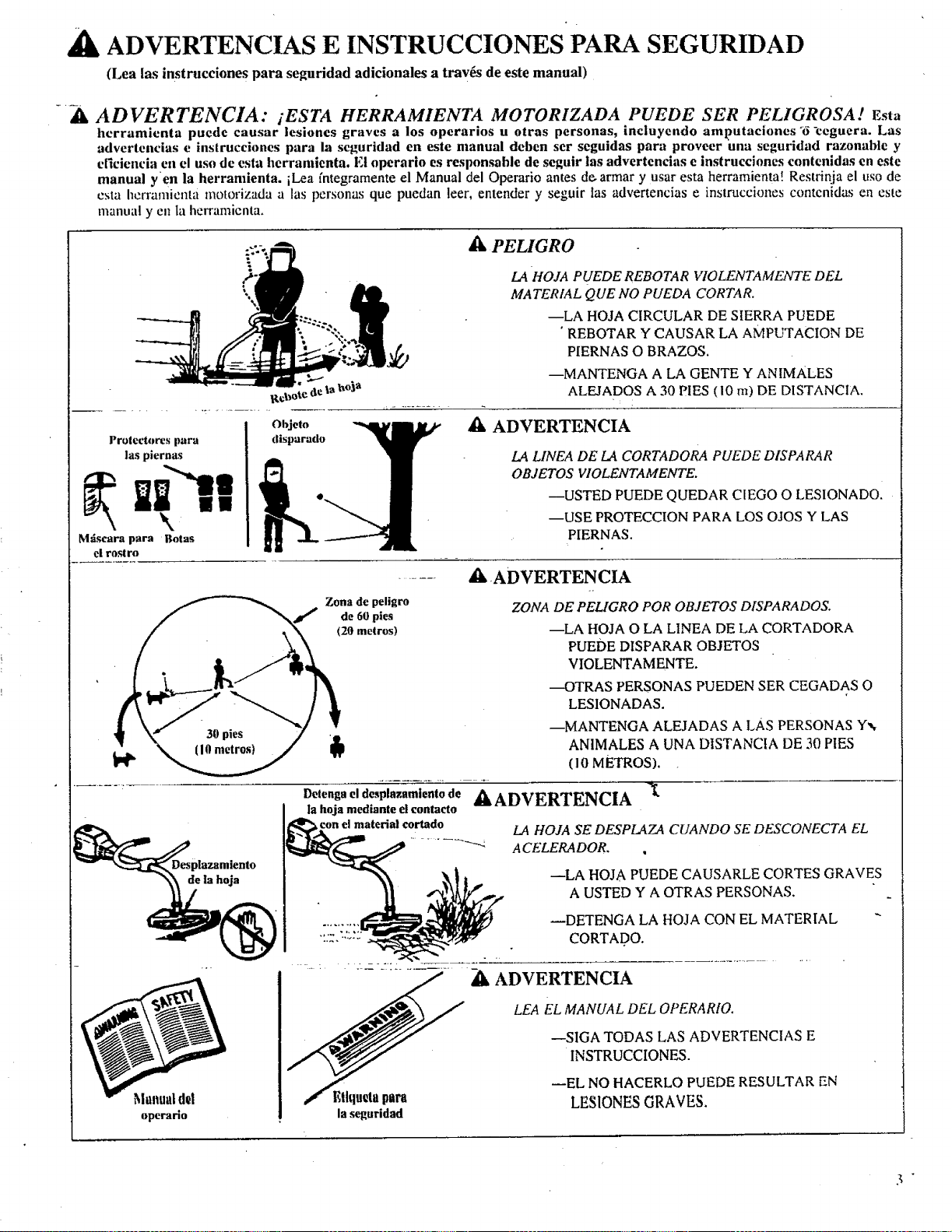
ADVERTENCIAS E INSTRUCCIONES PAPA SEGURIDAD
(Lea las instrucciones para seguridad adicionales a trav_s de este manual)
_, ADVERTENCIA: tESTA HERRAMIENTA MOTORIZADA PUEDE SER PELIGROSA[ Esta
hcrramienta puede eausar lesiones graves a los operarlos u otras personas, incluyendo amputaciones'_-ceguera. Las
adverteneias e instrucciones para la seguridad en este manual deben ser seguidas para proveer una seguridad razonable y
elicienei'a eu el uso de esta herramienta. El operario es responsable de seguir las advertencias e instrueciones contenidas en este
manual yen la herramienta, iLea fntegrameate el Manual del Operario antes de. armar y usar esta herramienta! Restrinja el uso de
esta herramienta motorizada alas personas que puedan leer, entender y seguir ias advertencias e instrucciones contcnidas en este
mam, al ycn ta herramienta.
i Objeto
Proteetores para disparado
las piernas
Mdscara para Botas
el rostro
Zona de peligro
de 60 pies
(20 metros)
Manual d_l
operarlo
1_.4HOJA PUEDE REBOTAR VIOLENTAMEArTE DEL
MATERIAL QUE NO PUEDA CORTAR.
--LA HOJA CIRCULAR DE SIERRA PUEDE
• REBOTAR Y CAUSAR LA AMPUTACION DE
PIERNAS O BRAZOS.
--MAWFENGA A LA GENTE Y ANIMALES
ALEJADOS A 30 PIES (10 n0 DE DISTANCIA.
A ADVERTENCIA
LA LINEA DE I_.4 CORTADORA PUEDE DISPARAR
OBJETOS VIOLENTAMENTE.
--USTED PUEDE QUEDAR CIEGO O LESIONADO.
--USE PROTECCION PARA LOS OJOS Y LAS
PIERNAS.
de la hoja
aXADVERTENCIA
ZONA DE PELIGRO POR OBJETOS DISPARADOS.
--LA HOJA O LA LINEA DE LA CORTADORA
PUEDE DISPARAR OBJETOS
VIOLENTAMENTE.
---OTRAS PERSONAS PUEDEN SER CEGADAS O
LESIONADAS.
--MANTENGA ALEJADAS ALAs PERSONAS Y_,
AN1MALES A UNA DISTANCIA DE 30 PIES
( 10 METROS).
Detenga el desplazamiento de
la hoja mediante el contacto
con el material cortado
Elhluglapain
la seguridad
AADVERTENCIA X.
LA HOJA SE DESPLAZA CUANDO SE DESCONECTA EL
A CELERADOR.
--LA HOJA PUEDE CAUSARLE CORTES GRAVES
A USTED Y A OTRAS PERSONAS.
_DETENGA LA HOJA CON EL MATERIAL
CORTADO.
A[_ADVERTENCIA
LEA EL MANUAL DEL OPERARIO.
--SIGA TODAS LAS ADVERTENCIAS E
INSTRUCCIONES.
_EL NO HACERLO PUEDE RESULTAR EN
LESIONES GRAVES.
ADVERTENCIAS E INSTRUCCIONESPARA LA SEGURiDAD (Cont')
"__IL SEGURIDAD DEL OPERARIO " ................. ServicioAutorizado.
• Use siempre protecci6n de seguridad para sus ojos, ' Zk SEGURIDAD PARA EL COMBUSTIBLE
• Use sicmpre pantalones largos, gmesos, botas, mangas largas y :, Mezcle y vierta el combustible en el exterior ....
guantes. Se rcconficnda el uso de protectores para las piemas.
No caminc dcscalzo ni use sandalias, joyen'a, pantalones cortos,
rn;ingas cortas, ropa suetta, nl ropa con corbatas, eorreas,
volados, etc. sueffos, ya quesc puedcn Irabar cn la eortadora. Et
estar totahnentc cubierto ayudar_ a protcgerlo de pedazos de
plantas t6xicas, talcs como la hiedra vcncnosa, impulsados pot la
hoja de la cortadbnl, quc poddan set m,SSpeligros0s que el tocar
la planta misma,
* Asegure su cabetlo para q0e quede sobre sus hombros.
. No ope_,eesta herramienta cuando usted est_i cansado, enfermo o
bajo ta influencia del,alcohol, drogas, o medicinas. Use
protecci6n para los ofdos si va a utilizar launidad por m_s de I y
1/2 horas por dia. .....
Nunca arranque o haga funcionat el motor dentro de un armario,
cuarto o edificio. El mspirar los gases del escape pueden matarlo.
- Mantenga los mangos libres deaceite y combustible,
• Use siempre et mango de sujeci6n y una correa para el hombro
. debidamente ajustada, Vea "Arnaado".
dX SEGURIDAD Y MANTENIMIENTO PARA LA
HERRAMIENTA
* Inspeccione la herramienta antes de cada Uso y reemplace las
piezas dafiadas. Revise por fugas de combustible antes de cada
uso. Mantenga la unidad en buen esgldo de funeionamienm.
, Descarte las hojas qt, e estfin torcidas,'combadas, rajadas o
dafiadas en cualquicr otra forma, Reemplace las piezas de la
cabeza de ta cortadora que estdn rajadas, astilladas, rotas o
dafiadas en cualquier otra tbrma antes de usar la herramienta.
- Mantenga la unidad de acuerdo a los procedimientos
recomendados. Mantenga Ia hoja afilada. Mantenga la lfnea para
cortar al largo apropiado.
- Use solamente la lfnea "Sears Laser Line" de .080" de difimetro.
Nunca use alambre, soga. cord6n, etc.
- lnstale en, Ibrma apropiada el escudo requerido antes de usar la
unidad. Use el escudo de metal para cualquier aplicaci6n de
corte co n h0jas. Use el escudo de plfis!ico para toda aplicaci6n
tic colic c0ti Ifnc'a. : '
Use solamente la hoja o ta cabeza especificada para la cortadora;
asegtlrese que est_i instalada en forma apropiada y ajustada.
Nunca arranque el motor sin la cubierta del embrague en su
lugar. El embrague puede salir disparado y causar heridas
graves,
- Asegfirese que Ia hoja o la cabeza de la c0rtadora se detiene
cuando el motor funciona en vaefo,
- Desconecte la bujfa antes de Itevar a cabo una tarea de
o .
,: Mantdngase alejado de chispas y llamas.
• Use un reclpiente aprobado para el'combustible.
• No filme ni perrnita que se fume cerca del combustible o de la
unidad o mientras se estd usando la unidad.
• Limpie todo derrame de combustible antes de arrancar €l motor.
, Al6je_se lYorlo menos 10 pies (3 metros) del lugar donde se calg6
la gasolina antes de arranear el motor.
Detenga el motor antes de sacar ia tapa del tanque de
combustible.
• Agote el combustible del tanque antes de guardar ta herramlenta.
Consuma el combustible que queda en el carbumdor an'ancando
el motor y dejfindolo funcionar hasta que pare por sf solo.
• Guarde ta herramienta y el combustible en un _irea donde los
vapors del combustible no puedan atcanzar a _hfspas o llamas
_ . abiertas de calentadores de agua, motores o interruptores
__ el6ctricos, hornos, etc.
_, SEGURIDAD PARA EL CORTE
....• inspeccione el firea que va a cortar antes de cada uso. Quite
• objetos (piedras, vidrios rotos, clavos; alambre, cuerdas, etc.) que
: puedan ser disparados o que puedan enredarse en la hoja o en la
cabeza de la cortadora.
• Mantenga.a otros incluyendo a nifios, animales, observadores y
ayudantes fuera de la Zona de Peligro de 60 pies (20 metros).
Pare el motor inmediatamente si alguien se le acerca.
• Mantenga siempre el motor en eI lado derecho de su cuerpo.
° Sujete la herramienta firmemente con ambas manos.
• Mantenga los pies firmes y su equilibfio. No extienda demasiado
los brazos.
• Mantenga la cabeza de la cortadora debajo del nivel de la
cintura.
° No levante el motor pot encima de la altura de su cintura.
• Mantenga todas tas partes de su cuerpo alejadas de la hoja o de
la cabeza de la cortadora y del silenciador cuando et motor est_i
en funcionamiento.
° Corte desde la derecha hacia la izquierda.
• :.Use su tmidad solamente pare Ins trabajos expticados en este
manual.
_IX TRANSPORTE Y ALMA CENAMIENTO ,
° Detenga el motor antes de Ilevar la unidad de un lugar a otto.
° Mantenga el silenciador alejado de su cuerpo. _ -
• Deje que el motor se enfrfe y asegure la unidad antes de
guardarla o transportarla en un Vehfculo.
• Antes de guardar o transportar la unidad, vacfe el tanque de
combustible. Consun_ el combustible que queda en las lfneas y
mantenimiento (excepto cuando se regula el carburador).
° Haga la regulaci6n det carburador con la cubierta del eje de
propulsi6n apoyada para evitar que la hoja o la lfnea de ta:
cortadora entre en contacto con cualquier objet0: Sujete ta
herranfienta con la mann; no use la eorrea opcional parael
hombro panl sujctar!a.
• Alejc a otras personas cuando esui haciendo la regulaci6n del
carburador
• Use solamente accesorios genuinos que son los recomendados
por Sears para esta hewamienta.
- Cuakluier mantenimiento o servicio que no ha sido explicado en
cste manuel se debt Ilevar a cabo por un Concesionario de
el carburador arrancando el motor y dejando que funcione hasta
que se pare por sf solo.
• Guarde Ia unidad y el combustible en un _l,ea donde los vapores
del combustible no puedan alcanzar chispas o llamas abiertas de
calentadores de agua, motores o inten'upt0res eldctricos, hornos.
etc.
• Guarde la unidad de tal manera que la hoja o el limitador de "la
lfnea no pueda causar lesiones accidentalmente. La unidad pu_,de
ser colgada del soporte que tiene debajo del motor o por la
cubierta det eje de propulsi6n.
• Guarde la herramienta fuera del alcance de los nifios.
Si ocurren situaciones que no esMn cubiertas en este manual, tenga cuidado y use buen juicio.
Consulte con stt Departamento o Cetttro de Servicio si necesita ayuda.
TELEFONO DE EMERGENCIA PARA AYUDA A LOS CLIENTES: 1.800-235-5878
• AVISO DE SEGURIDAD
l,_ €¢,hqtNcifina hts vibraciones debid_ al uso prolongado de herramienti_8manuales a motor de gasolinn podria cattsar dafios a los
t | I I | I I
t 1 I _ 11 | It
n_tvlo_tl_10_d_do_, la_nlan0s y ht_tttufi_a_d_ plt_0ltttssu_e_!tllbl_a enl'mttMatlo_deeulal0das o hhtdlitZOnt,._an0r'llltde._,I,;1u._.
prolongado de tales herramientas en tiempo frfo ha sido atribuido eomo la eausa de dafios a los vasos sanguineos en personas pot 1o
denr, k_ saludables. Si se presentan sfntomas eomo adormeeimiento, dolor_ p_rdida de fuerza, cambio en la ¢oloracidn de la piel o de su
textura o p_rdida de la sertsibiUdad en los dedos, las manos o las mufieeas, d|scontimie el uso de esta herramienta y lmsque atenci6n
m_d|ca. Un sistema anti-vibratnrio no garantiza el evitar estos problemas. Los usuarios que operan herramientas motorizttdas en
forma continua y regula r deben observar cuidadosamente sus ¢ondiei6n ffsiea y el estado de esta herramienta.
CONOZCA SU HERRAMIENTA
A_
B_
INTRODUCCION
Su cortadora Weedwacke( r'_ es un producto de alta calidad y
estfi disefiada para tareas pesadas. Su versatilidad le ayudar_i a
llevar a cabo con facilidad una variedad de tareas.
Las caracter/sticas especiales incluyen:
• iloja reversible de cuatro puntas para pasto, yerba y
malon'alcs de hasta I/2" (13 ram) de difimelro.
• Cabeza con alimentaci6n automfitica de la ffnea para
podar, conar, barfer y para cortar al ras.
INSTRUCCIONES PARA DESEMPACAR
I. Saque el conlenido de la caja si lodavfa no Io ha hecho.
2. Compruebe tas piezas t:ontra latista que sigue.
3. Examine Ins piezas por dafios. No use las piezas que estfn
dafiadas.
4. Notifiqtte a su tienda Sears inmediatamente si falta algtma
pi_,za o estd d_tfia_kt.
Su unidad ha sido despachada con una cubierta de
pkistico para el transporte encima de la bombilla para cebar el
carburador (Vea "Especificaciones" pot su ubieaci6n): Saque
y deseche la cubierta plfistica para el transpone.
Es normal escuchar el tinlineo del filtro de
combustible en un tanque de combustible vacfo.
C. CONTENIDO DE LA CAJA
CLAVE
NO.
* Molor
o Conjunto del eje de proputsidn y caja de eojinetes
con la etiqueta de seguridad
. Manubrio
Escudo de plfistico - Cabeza de la conadora
- Cabeza de la cortadora
Escudo de metal - Hoja
* Hoja para hierba, 8 pulgadas, 4 puntas
° Corrca para el hombro_ con advenencia
Aeeile para motor de 2 tiempos
Manuat del operario (no se muestra)
Bolsa con piezas sueltas (no sc mucslra}
**CONTENIDO DE LA BOLSA CON PIEZAS SUELTAS:
• Bloque para montaje - Manubrio
- Cubierta - Manubrio
. Grapa de la correa para el hombro
- Asa en "T"
* Llave hexagonal (Chica)
• Llave hexagonal (Grande)
- Lubricante para el eje flexible
A Tuerea hexagonal - Motor
B Tomillo - Manubrio
C Tomillo hexagonal - Cubierta del gatillo det acelerador
D Tornillo - Escudo phistico
E Tornillo de cabeza cuadrada
F Arandela plana - Hoja
G Arandela blselada - Hoja
H Arandela hexagonal con brida - Hoja
I Tuerca hexagonal - Motor
J Tuerca hexagonal -- "
K Arandcla de copa grandc - Cabeza de la cortadora
L Plata de retenci6n - Escudo de metal
CANT.
1
I
2
I
1
1
1
1
2
8
1
4
1
1
I
1
2
1
1
1
D. Uso de los tornillos, tuercas y arandelas NOTA." Estos tornillos, arandelas y tuercas vienen en la bolsa de
plfistico. Refi_rase alas letras de abajo durante el armado de su unidad.
Objetos mostrados en su tamafio real
%.
£. B. -C. D.
E
IIIIlIIllIl||IIIIl
.=. ...............
E_
@©
I. .1.
• Ki ._
ARMADO
(Si la herramienla t_ reciba armada, repita todos los pasos en esta secci6n para asegurarse que _s_ correctamante armada y
regulada para el operario.)
PREPARACION
Este manual dcl opcrario ha sid_ de_arrollado para ayudarle a
usted a armar la herramienta y para que su operaei6n sea segura.
Es importante que usted lea el manual fntegro para familiarizarse
con la herramienta antes que nsted empiece a armarla. Si usted
tiene cualquier pregunta o necesita ayuda adicional, tlame
nuestro TELEFONO DE EMERGENCIA PARA AYUDA A
LOS CLIENTES at 1-800-235-5878+
I. Lea su manual del operario.
2. tlerramientas que usted neeesitard:
- Las Ilaves hexagonales provistas con la herramienta
- Una Itave regulable
- Un destornillador standard
PASOS PARA EL ARMADO (Refer to illustrations)
Tubo
w
Coloque los dos tornillos "A" en los orificios de Ia guarda
del embrague. Asegtirese que los tornillos est6n bien
asentados en los orificios,
Coloque las tuercas "!" en +los orificios inferiores.
Apriete Ios tornillos con Ia llave hexagonal chica provista,
s61o 1o suficiente para sujetar juntas las piezas, mientras
que co!!+ la otra rimno sujcta las tuercas de seguridad+
Saque_iia tapa de embarque del extrcmo recto de Ia caja del
ejc de propulsi6n. Su herramienta puede no tenet una tapa
de embarque.
Asegdrese que el eje de propulsi6n flexible no se
cae fuera de la caja del eje de propulsi6n. La presencia de
tierra en el eje reducir_i considerablemente el tiempo de
vida de_,la herramienta. Si el eje de propulsi6n flexible eae
fuera de la_¢aja, lfmpielo, ctibralo con lubricante y vuelva
a instalarlo+ Vea "Lubricaci6n del ejede propulsi6n
flexible" en la secci6n Mantenimiento.
t _ Tornillo"A"
\'/ / Quite el material de embarque
_ /_xJ .... del extremo del tubo (so Io
Tubo
r',/
Vista alimentada
Orifieio c_adrado + Ranura superior
Lomo y ranura
inferior
Gire el arbol para
alinear el eje con el
oriflelo cuadrado.
Arbol
o
Alinee la ranura en Ia caja del eje de propulsi6n con el
lomo en ta pared interior inferior de la abertura de la
guarda del embmgue.
Gire el zirbol como sea necesario para alinear el extremo
cuadrado del eje de propulsi6n flexible con el interior
cuadrado de la abertura de la guarda del embrague.
Empuje firmemente el tubo en la apertura del motor hasta
que la ranura superior no se vea m_is.
Apri+ete los tornillos "A" alternativamente con la llave
hexagonal pequefia hasta que queden asegurados.
2. CABLE DEL ACELERADOR
[PRECAUCION: ] No doble e! ta!kie del ace!erador.
a. Deslice la caja dcl gatillo deI acelcrador alejzindola del mango
de cspuma.
NOTA: Antes de tlevar a cabo el paso "b", introduzca el
extremo con el tambor det cable del acelerador dentro de la
cubierta hasta que el tambor tome contacto con la cubierta.
b. Inserte el cable del acelerador a trav6S del ttlnel en el mango
tic cspuma hasta quc cl extl'cmo dcl cable se extienda pot: Io
mcnos dos pulgadas m:is allzi del mango,
c, Sujete cl gatillo alejado de la cubierta del eje de propulsi6n e
inserte et extremo del tambor del cable del acelerador dentro
det orificio redondo en el gatillo.
NOTA: AI insertar el extremo del tambor del cable del
acelerador dentro det orificio redondo en el gatillo, asegttrese
que el tambor quede completamente insertado:y que el cable
del acelcrador est6 situado en la hendidura det brazo.
d. Empuje el gatillo de regreso dentro de la cubierta, mientras
gufa et cable a trav6s de Ia hendidura en el brazo. Gufe el
brazo dentro del tdnet del mango de espuma mientras vuelve
a colocar la caja del gatillo del acelerador al ras contra el
mango de espuma.
e. Sujete el gatillo contra el mango de espuma mientras inserta
c! tornillo y !a t_uerca. Tome nora de la precauci6n mils abajo.-
[PRECAUC!ON:INo apriete demasiado el tornillo,
Asegdrese que el gatillo se mueve libremente. Debe haber
por!o inenos 1/8" (3 mm) de juego en el gatillo. Asegfrese
que el gatillo se moverd libremente para que el motor
pueda volver a funeionamlento en Vae[o cuando se suelta
el gatiilo. La cabeza de la cortadora no debe girar cuando
el motor estfi funcionando en vacio para evitar lesiones
graves al operario y a otras personas.
3. MANGODE APOYO
I A ADVERTENCIA
E! bloque para el montaje del manubrio debe ser colocado
encima de la punta de ia flecha que tienen Ins etiquetas de
seguridad. E! manubrio es una defensa para mantener la hoja
alejada de los pies del operario.
a. Cotoque cualquiera de los lados deI bloque para el montaje en
la cubierta dcl eje de propulsi6n pot encima de la flecha en
Ins etiquetas de seguridad.
b. Cok_quc una d¢ Ins eubiertas por debnjo de la cubierta det eje
de propulsi6n y asegt_relo con dos tornillos al bloque de
montaje.
c, Alinee el manubrio con la porci6n recta que es la porci6n de
la barrera hacia la izquierda y la porci6n c'urva hacia la
derecha.
d. Coloque el bloque de montaje entre Ins flechas en la secci6n
corta y recta del manubrio.
e. Ponga la cubierla reslante sobre el manubrio y asegtireta con
dos tornil[os. Apriele s6lo con la mano.
f. Ascgtiresc quc cl mat_ubrio cstfi instalado en forma correcta,
y luego apriete cada tornillo con una Ilave basra que quede
bicn asegurado.
A AI)VERTENCIA
i,a I){w,_i6nrecta, largll d¢l lunnulwi0 dd_€ (lucdar insttllada
para proveer de una barrera entre el operador y la hoja que
gir_.
del cable
Brazo
i
Cable t
i
I 1/8" de juego _
I
I
Tornillo "C"
" Porci6ri :[ / Mango" •
• - curva __ I _./
_"_. " _.- _'_ /"_x Porci6n de _"
- _:_,_ -, ,i.i_ /S,,_',," la barrera
' L____co a
:. __--Bloque para el montaje
• Tornillo "C"
©
Porci6n
curva
Pb_d6-n--re_cffi,
corta
Bloque para el
montaje
//
seguridad
Cublerta ,
-C §9
7
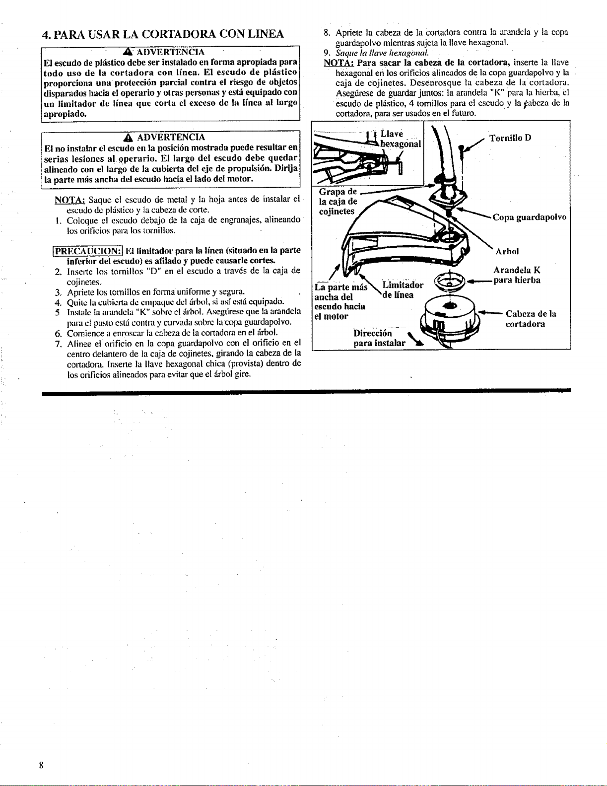
4. PARA USAR LA CORTADORA CON LINEA
al_:ADVERTENCIA
E! escudo de plfistico debe ser instalado en forma apropiada para
todo uso de la cortadora con lfnea. El escudo de phistico
- 11oroporciona una orotecci6n parcial contra el riesgo de objetos
disparados hacia el operario y otras personas y estti equipado con
un iimitadur de lfnca que corta el exceso de la ffnea al largo
apropiado.
, _IL ADVERTENCIA
E! no instalar el escudo en la posici6n mostrada puede resultar en I
serias lesiones al 0perario. El largo del escudo debe quedar I
alineado con el largo de la cubierta del eje de propulsi6n. Dirija]
la parte m_is ancha del escudo hacia el iado del motor. 1
NOTA: Saque el escudo de metal y la hoja antes de instalar el
escudo de pkistico y la cabeza de torte.
!. Coloque el escudo debajo de ta caja de engranajes, alineando
los orificios par, a los tornillos.
fPRECA ! ICION: I El limitador para la ffnea (situado en la parte
inl_rior dei escudo) es afilado y puede causarle cortes.
2. Insecte los tornillos "D" en el escudo a trav6s de Ia eaja de
cojinetes.
3o Apriete los tornillos en forma unifom_e y segura.
4. Quite la cubierta de cmpaque dcl firbol, si asf cslfi equipado.
5 Instalc ta arandcla "K" sobre el ;h'bol. Asegfirese que la arandela
para cI pasto estfi co|llra y culwada sobre la copa guardapolvo.
6. Comience a enro._car la cabeza de la cortadora en el firbol.
7. Alinee et orificio en la copa guardapolvo con el orificio en el
centro de[antero de la caja de cojinetes, girando la cabeza de ta
conadora. Inserte la Ilave hexagonal chica (provista) dentro de
los orificios alineados para evitar que el firbol gire.
Ill Ill
IIIllllllIllllllllll I Ill IIllll
8. Apriete la cabeza de Ia Cortadom contra la arandela y la €opa
guardapolvo mientms sujeta ta Ilave hexagonal.
9. Saque la llave he.ragonaL :
NOTA: Para sacar la cabeza de la cortadora, inserte ta [lave
hexagonal en los orificios alineados de la copa guardapolvo y la
caja de cojinetes. Desenrosque Ia cabeza de la cortadora.
Asegfirese de guardar juntos: la arandela "K" para la hierba, el
escudo de plfistico, 4 tomillos paca el escudo y la _abeza de ta
cortadora, para set usados en el futuro.
Llave TorniUo D
,hexagdr
'Limitador
ancha del
escudo hacta
el motor
Direcci6n
para
Arbol
Arandela K
.,_..-.- para hierba
Cabeza de la
cortadora
IIIll IIllllll
IllIllIlllII I Ill Illlll

5. PARA USO CON HOJA CORTADORA DE
HIERBAS
A ADVERTENCIA
El escudo de metal debe estar instalado en forma apropiada
toda vez quela herramienta sea usada con la hoja. La punta
delantera del escudo de metal ayuda a reducir el riesgo de que
ocurra un rebote de la hoja, !o cual puede causar lesiones serias,
tales conm amputaciunes, al operario y a los observadores.
/_ ADVERTENCIA
E! no instalar el escudo en la posici6n mostradapuede resultar
en iesiones graves al operario. La parte larga del escudo debe
estar alineada con el largo de la cubierta del eje de propulsi6n.
DiriJa la parte mils ancha del escudo hacia el lado del motor.
IPRECAUCION:] Para evitar lesiones, use guantes de
protecci6n cuando hace servicio de mantenimiento a la hoja.
NOTA: Saque el escudo de pl6.stico, ta cabeza de la cortadom y
la arandela para hierbas antes de instalar el escudo de metal y la
hoja.
a. Coloque el escudo de metal debajo de la cubierta del eje de
propulsidm alineando los orifieios. Compruebe que el
extremo ancho del escudo de metal est6 hacia el lado del
molor.
b. Coloque la ptaca de retencidn en la pane inferior debajo del
. _2SCtltlo de metal y alinec los orificios para los tornillos.
C0mpruebe que el lado phmo de la placa estfi contra el
escudo.
e. lnserlc los cuatro ttmfillos para el escudo de metal (uno a la
vez) a travds de la eubierta del eojinele, el escudo y la placa
de _cnlenci6n.
d. Apriete los tornill0s en forma ahernada coil una llave
hexagonal.
g*
h.
i.
j.
k.
1.
hi.
e,
f.
lnstale la copa guardapolvo en el zlrb01.
lnstale ta hoja en el firN_l, asegunindose que el orificio en el
ccntro de la hoja se acomode alrededor de la grada elevada
de la copa guardapolvo.
Instale la arandela plana grande, la arandela biselada y la
tuerca hexagonal para la brida.
Alinee el orificio de Ia copa guardapolvo con el orificio en el
lado de la cubicrta det cojincte, girando la copa guardapolvo.
Inserte Ia llave hexagonal chica provista en los orificios
alineados para evitar que el zh'bolgire.
Apriete firmemente la tuerca hexagonal de la brida con una
llave mientras sujeta la varilla en su posici6n.
Saque la Ilave hexagonal.
Gire la hoja con la mano. Si la hoja se traba contra e! escudo,
ta hoja no estti centrada. Vuelva a instalar la hoja.
Confintie con las insmacciones para la correa para et hombro
en esta secci6n.
Para sacar la hoja, inserte la varilla dentro de los
orifici_s alineados. Descnrosque la tuerca hexagonal de la
brida y saque las piezas. Asegfirese de guardar juntas la
placa dc retcnci6n, la merca hexagonal para la brlda, la
lrilnddilbi ¢hldi!,lilaranddilpluni y hojta
para mayor scguridad.
" " k
L
L • •
"-- Tornillo _'
Grapa de ./['!
.- la caja del
157!
r-2gr-
i .... Copa
rePlan3;id?n_ " ___guardapolvo
Hoja* .... J" plana*
I
..- randela
biselada*
"G"
7- _"_Tfierca de
la brida*
- ;;, ,_, ........
Llave hexagonal
El lado
hondo hacia
la hoja
Arandela "G"
* _fi, ADVERTENCIA ]
Las piezas mareadas "*" son crfticas y deben ser provistas pot I
Sears. El no mar las piezas apropiadas puede causar que la hoja
salga volando y le ocasione lesiones graves a usted o a otras l
personas. " !
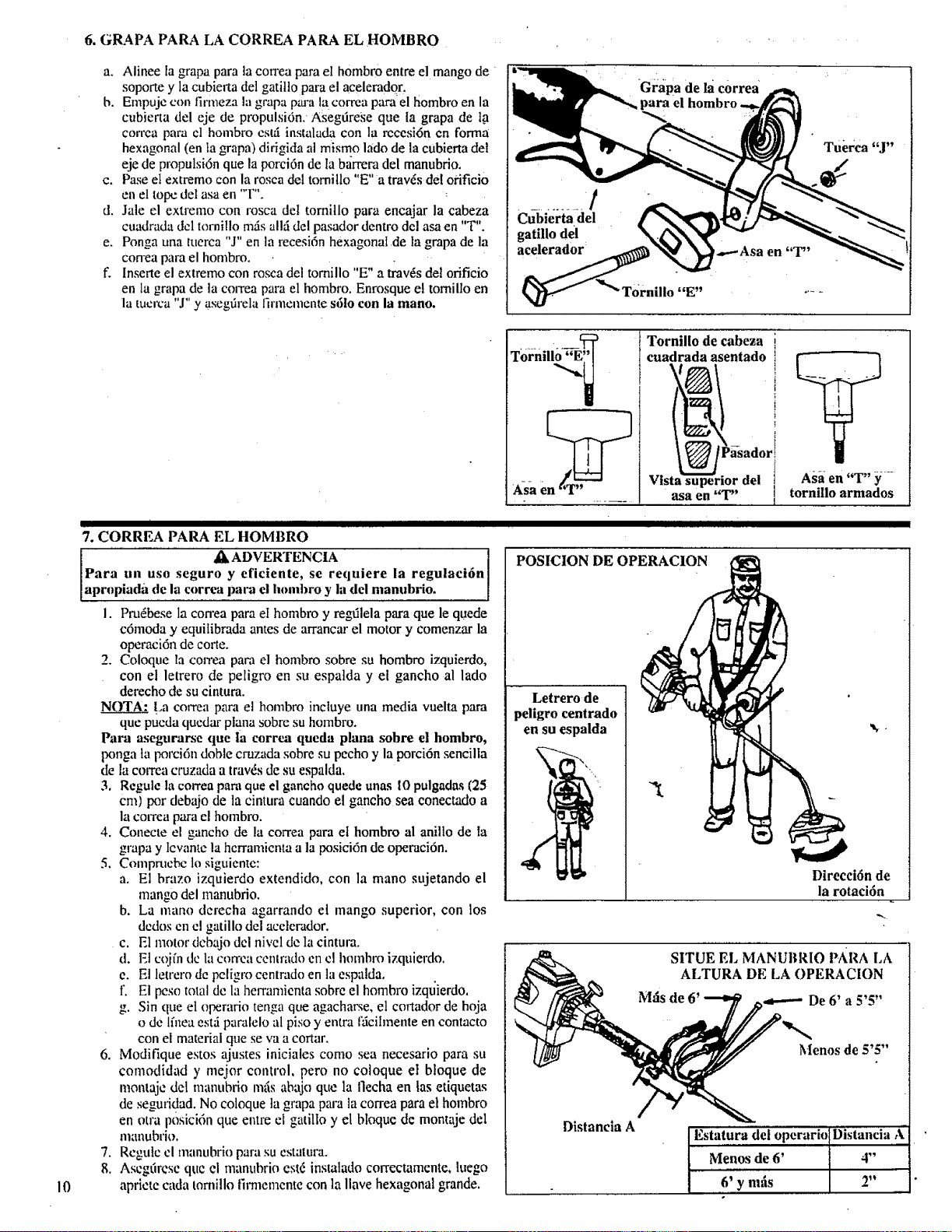
10
6. GRAPA PARA LA CORREA PARA EL HOMBRO
a. Alinee la grapa para la correa para el hombro entre el mango de
soporte y la cubierta del gatitto para el acelerador.
b. Empujc con fi,-meza la grapa para lacorrea para el hombro en la
cubierta del eje de propulsi6n: Asegtirese que la grapa de la
co,'rca para el hombro cstr_ instalada con la rccesi6n en forma
hexagonal (en la grapa) dirigida al mismo lado de la cubierta det
eje de propulsi6n que la porci6n de la barrera del manubrio.
c. Pase eI extremo con la rosca del tornitlo "E"a trav_s del ofificio
en el tope del asa en "°r".
d. Jale el extremo con rosca det tornillo para encajar la cabeza
cuadrada del tornillo ross allti del pasador dentro del asa en "T".
e. Ponga una tuerca "J" en la recesi6n hexagonal de Ia grapa de la
con'ea para el hombro.
f. Inserte el extremo con rosca del tomillo "E" a trav4s del orificio
en la grapa de la coIrea para el hombro. Enrosque et tomiUo en
la tucrca "J" y asegfirela llrmemente s61o con la mano.
............
Cubiertadel
gatillo del
{_ _" Tornillo "E"
[ IllllllIllll Illl Illll I I I I Illll
7. CORREA PARA EL HOMBRO
Tornili__
Asa en '_TI''
1. Pru6bese la con'ea para el hombro y regtilela para que le quede
c6moda y equilibrada antes de arrancar el motor y comenzar la
operaci6n de corte.
2. Coloque la correa pava el hombro sobre su hombro izquierdo,
con el letrero de peligro en su espatda y el gancho al lado
derecho de su cintura.
La correa para el hombro inctuye una media vuelta para
que pueda quedar plana sobre su hombro.
Para asegurarse que la correa queda plana sobre el hombro,
F,onga la porcidn doble cruzada sobre su pecho y la porci6n sencilla
de la correa cruzada a tray,s de su espalda.
3. Regule la correa para que el gancho quede unas tO pulgadas (25
cm) por debajo de la cintura cuando el gancho sea conectado a
la COiTeapara el hombro.
4. Conecte el gancho de la correa para et hombro al anillo de la
grapa y lcvante la hcrramienta a la posici6n de operaci6n.
5. Comprucbc to siguiente:
a. El brazo izquierdo extendido, con la mano sujetando el
mango del manubrio.
b. La mano derecha agarrando el mango superior, con los
dedos cn el gatillo del ace!ecador.
c. El motor dcbajo dcl nivcl de la cintura.
d. El cojfn tie la con'ca cenlrado en cl Immbro izquierdo.
e. El letrero de peligro centmdo en la cspatda.
f El peso total de la hen'amicnta sobre el hombro izqt_ierdo,
g. Sin que el operario tenga que agacharse, et cortador de hoja
o de lfnea e.st_iparalelo al piso y entra fticihnente en contacto
con el material que se va a cortar.
6. Modifique estos ajustes iniciales como sea necesario para su
comodidad y mejor control, pero no coloque el bloque de
montajc det manubrio mils abajo que la flecha en las etiquetas
de seguridad. No coloque la grapa para la correa para el hombro
en otra posici6n que entre el gatillo y el bloque de montaje del
nlatlubrio.
7. Rcgulc cl manubr[o para su cstatura.
8. Ascgtircse que el manubrio estd instalado correctamente, luego
apriete cada tornillo firmemente con la llave hexagonal grande.
Tornillo de cabeza
cuadrada asentado
r
asa en "T" ]
I
Asa en "T" y
tornillo armados
lilt L I I1[ tlJI I
POSICION DE OPERACION
Letrero de
peligro centrado
en su espalda
Direcci6n de
la rotaci6n
SITUE EL MANUBRIO PARA LA
ALTURA DE LA OPERACION
M:is de 6' _ De 6' a 5'5"
Menos de 5'5"
Distancta A
Estatilra del operario Distancia Ai
Menos de 6' 4"
6' y naris 2"
I_ III IIIII I L III I IIII " I I II IIIIIIIIIIIIIIIIIIIIIIII
CARGANDO COMBUSTIBLE A SU :MOTOR ......
I II I IIIIIIIIIIIIII IIII Inllllll I I I
' ANTES DE CARGAR COMBUSTIBLE A SU MOTOR
,? :
'_k ADVERTENCUA ....
Asegtlrese de leer la secci6n de informaci6n de seguridad del
€ombustible en tas Advertencias e Instrucciones de
Seguridad en la p_igina 4 de este manual antes de comenzar.
NO trate de cargar combustible a su unidad si no comprende
la secci6n de seguridad del combustible; requiera ayuda de
alguien que eomprend a la secci6n de seguridad del
combustible o ilamea la Linea de Emergencia de Asistencia
al Cliente al 1-800-235-5878.
i COMBUSTIBLE
El motor de dos tiempos de este product0 requiere una mezcla de
combustible de gasolina regular sin plomo y un aceite de motor de
alta calidad para lubricaci6n de los rodamientos y otras partes
m6viles. La mezcla correcta de combustiblelaceite es de 40:1 (yea
ta Tabla de Mezcla de Combustible). Muy poco aceite o el tipo
ineorreeto de aceite causar5 un real rendimiento y haril que el motor
se sobreealiente y atasque,
La gasolin a y el aceite dcben premezclarse en un recipiente de
gasotina limpio y aprobado. Siempre Use gasolina fresca sin plomo.
IMPORTANTE; La cxpcriencia indica que los combustibles
mezelados con alcohol llamados ga_ohol (o que usan etanol o
metanol) pueden atraer la humedad. Io que produce la separ.aci6n y
formaci6n de ficidos durante el almacenaje. El gas acfdico puede
dafiar el sistema de combustible de un motor mientras est_i
almacenado. El sistema tie combustible deberfa vaciarse antes de
almacenar por 30 dfas o mils. para evitar problemas con el motor.
Vacfe el tanque d e gasotina y a continuaci6n vacfe el combustible
del carburador yl de lax tuberfas arrancando el motor y dejilndoto
funcionar hasta que se detenga. Use gasolina fresca en la pr6xima
estaci6n. Vea 1as instrucciones de ALMACENAMIENTO para
informaci6n adicional. Nunca use productos limpiadores para motor
o carburador en'el tanque de combustible ya que pueden causar
dafios permanentes.
ESTABILIZADOR DE COMBUSTIBLE
El estabilizador de combustible es una alternativa aceptabte para
minimizar la formaci6n de dcp6sitos de goma del combustible
durante el almaccnamiento. Agreguc el estabilizador a la gasolina
en el tanque de combustible o en el recipiente de almacenamiento.
Siempre observe la proporci6n de mezcla de combustible indicado
en el recipiente del estabilizador. Haga fu,cionar el motor durante
10 minutos por Io mcnos despuds de agregar et estabilizador, para
permitir que el estabilizador Ilegue at carburador. Usted no tiene
que vaciar el tanque de combustible para el almacenamiento si estil
usando un cstabilizador de combustible.
Et aceite de motor de 2 tiempos 40:1 CRAFTSMAN estil
especialmente mezclado con estabilizadores de combustible. Usted
puede agregar un estabilizador de combustible (tal como el
Craftsman No. 33500) a su tanque de combustible, si no usa este
aceite Sears.
ii i ii i¸¸ ' " n iiii ii=|nl
:i :ACEITEDE::.... : 2TIE POSM -: : ' " :
El , :
aceite de motor de 2 tiempos 40:1 CRAFTSMAN se recomienda
altamente. Este aceite estfi especiatmente mezclado con
estabilizadores de combustible para una estabilidad mayor del
combustible (extiende la duraci6n del combustible hasta cinco
vcces) y menos gases de escape.
Si noestil disponible el aceite de motor de 2 tiempos 40:1
CRAFTSMAN use un aceite para motores de dos tiempos
ENFRIADOS POR AIRE de buena calidad'que tenga una mezcta
recomendada de Combustible de 40:1,, :
ilMPORTANTE! No use:
• ACEITE AUTOMOTRIZ
• ACEITE PAR?'. MOTORES DE BOTES
(NMBA, BIA, etc.)
Estos aceites no tienen los adilivos apropiados para motores de
dos tiempos ENFRIADOS POR AIRE y pueden causar dafios al
motor.
MEZCLA DE GASOLINA Y ACEITE
Mezcle la gasolina y el aceite como sigue:
, Consulte la tabla para ias cantidades correctas.
• No mezcle la gasolina y el aceite directamente', en el tanque
de combustible. : :
PARA UN GALON:
Vierta 3,2 onzas de aceite de motor de 2 tiempos de buena
calidad en un recipiente aprobadode gasolina de un gal6n.
Agregue un gal6n de gasolina regularsin plomo at recipi_te
de un gal6n y a continuaci6n co!oque y ajuste bien la tapa.
Sacuda el recipiente durante unos instantes.
• La mezcla est.4 aho_ lista para usar. Puedc agregar.se el
estabilizador de combustible en este momento de desearse:
observe las instrucciones de mezclado en la etiqueta.
TABLA DE MEZCLA DE COMBUSTIBLE
Proporci6n de mezcla de combustible:aceite 40:1
Aceite (oz,fl.!
1 gal6n 3,2
1,25 galones 4,0
2,5 galones 8,0
I1
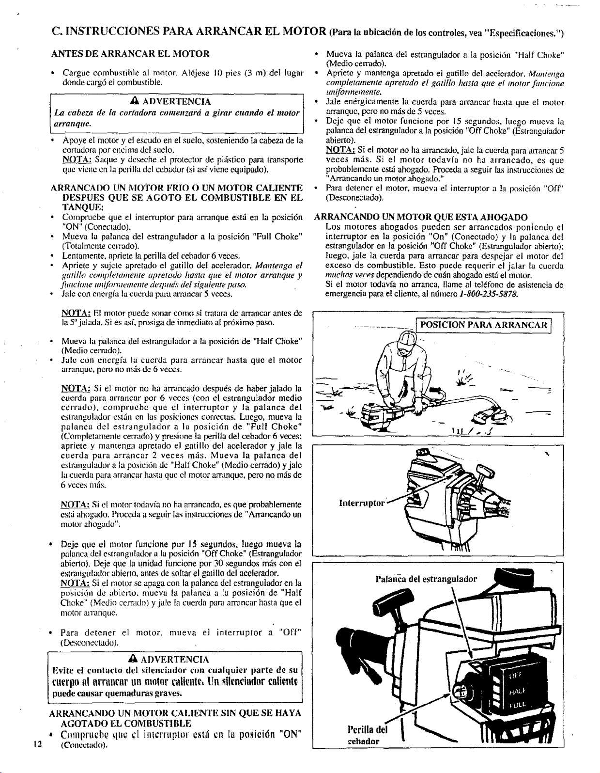
12
C. INSTRUCCIONES PARA ARRANCAR EL MOTOR (Para la ubicaci6n de los controles, vea "Espeeificaciones.")
ANTES DE ARRANCAR EL MOTOR
,, Cargue combustible al motor. Al6jese 10 pies (3 m) det [ugar
donde carg6 el combustible.
,_ ADVERTENCIALa cabeza de la cortadora contenzar6 a girar cuando el motor
arranque.
• Apoye el motor y el escudo en el sueto, sosteniendo Ia cabeza de la
cortadora por encima del suelo,
NOTA: Saque y dcseche el protector de plfistico para transporte
que vicne cn la pcrilla dcI ccbador (si asf viene equipado).
ARRANCADO UN MOTOR FRIO O UN MOTOR CALIENTE
DESPUES QUE SE AGOTO EL COMBUSTIBLE EN EL
TANQUE:
- Compruebe que el interruptor para arranque estfi en la posici6n
"ON" (Conectado).
• Mueva la palanca del estrangulador a la posici6n "Full Choke"
(Totalmente cen'ado).
• Lentamente, apfiete la perilla del cebador 6 veces.
• Apriete y sujcte apretado el gatillo del acelerador. Mantenga el
gatillo conqdetamente apretado hasta que el motor arranque y
funchme un(]2mnetnente de._Tmt_s"del siguiente paso,
• Jale con energf'a la cucrda para atTancar 5 veces.
• Mueva la patanca del estrangulador a la posici6n "Half Choke"
(Medio cerrado).
° Apriete y mantenga apretado el gatillo de! acelerador. Mantenga
completamente apretado el gatillo hasta que et motor fimcione
uniformemente.
• Jale endrgicamente la cuerda para arrancar basra que el motor
arranque, pero no mLs de 5 vcces.
• Deje que el motor funcione por 15 segundos, Iucgo mueva la
palanca del estrangulador a Ia posici6n "Off Choke" (Estrangutador
abierto).
Si el motor no ha arrancado, jale la cuerda para arrancar 5
veces mils. Si el motor todavfa no ha arrancado, es que
probabtemente est_ ahogado. Proceda a seguir [as instmcciones de
"Arrancando un motor ahogado."
• Para detener el motor, mueva el interruptor a la posici6n "Off"
(Desconectado).
ARRANCANDO UN MOTOR QUE ESTA AHOGADO
Los motores ahogados pueden ser arrancados poniendo el
interruptor en la posiei6n "On" (Conectado) y la patanca det
estrangulador en la posici6n "Off Choke" (Estrangulador abierto);
luego, jate la cuerda para arrancar para despejar el motor del
exceso de combustible. Esto puede requerir el jalar la cuerda
muchas veces dependiendo de cufin ahogado estfi el motor.
Si el motor todavfa no arranca, IIame al teI6fono de asistencia de
emergencia para el cliente, al ndmero 1-800-235-5878.
El motor puede sonar como si tratara de arrancar antes de
la 5"jatada. Si es asL prosiga de inmediato a[ pr6ximo paso.
• Mueva la palanca del estrangulador a la posicidn de "Half Choke"
(Medio cen-ado).
° Jale con encrgfa la cuerda para arrancar hasta que el motor
arnmque, pero no mils de 6 veces,
NOTA: Si el motor no ha arrancado despu6s de haber jalado la
cuerda para arrancar por 6 veces (con el estrangulador medio
cerrado), compruebe que et interruptor y la palanca del
cstrangulador cst6n en las posiciones con'cctas. Luego, mueva la
palanca del estrangulador a la posicidn de "Full Choke"
(Completamente cerrado) y presione la peritla del cebador 6 veces;
apriete y mantenga apretado el gatillo del acelerador y jale la
cuerda para arrancar 2 veces mils. Mueva la palanca del
cstrangulador a la posicidn de "Half Choke" (Medio cerrado) y jale
la cuerda para atTancar hasta quc el motor arranque, pero no m,4sde
6 veces m,'is,
NO'I'A;. Si el motor todavfa no ha arrancado, es que probablemente
eslfi ahogado. Proccda a seguir lax instrucciones de "Arrancando un
motor ahogado!'.
Dcje que el motor funcion¢ pot 15 segundos, luego mueva la
palanca del estrangulador a la posici6n "Off Choke" (Estrangulador
abieao). Deje que la unidad funcione por 30 _gundos m_ts con eI
estrangulador abieno, antes de soltar el gatillo del acelerador.
NOTA: Si el motor se apaga con la palanca del estrangulador en la
posici6n de abierto, mueva [a pa[anca a [a posici6n de "Half
Choke" (Medio ccvrado) y ja[e la cuerda para arrancar hasta que el
motor arranque.
• Para dctener el motor, mueva el interruptor a "Off"
(Desconectado).
ADVERTENCIA
Evite el cont'lcto del silenciador con cualquier parte de su
cucrl| |ill zrrzmcurun m0tqlrt'zdicnt ,Un 8ilenciador alicnt
puede causar quemaduras graves.
ARRANCANDO UN MOTOR CALIENTE SIN QUE SE HAYA
AGOTADO EL COMBUSTI BLE
• C0mprt£cb¢ tlU_ ¢1 inlcrruplor cstti cn la posicidn "ON"
(Conecl,ldo),
_ [ POSICION PARA ARRANCAR I
' llL1,.,._
Palanca del estrangulador
Pcrill8 del
cehador
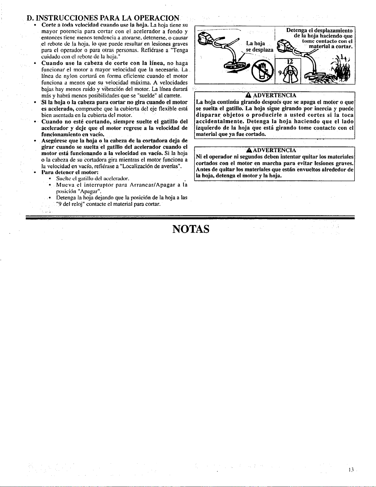
D. INSTRUCCIONES PARA LA OPERACION
• Corte a toda velocidad cuando use la hoja, La hoja tiene su
mayor potencia para c0rtar con e! acelerador a fondo y
entonces riene menos tendencia a atorarse, detenerse, o causar
el rebote de Ia hoja, 1o que puede resultar en lesiones graves
para el operador o para otras personas. Refi6rase a "Tenga
cuidado con cI rebote de la hoja."
• Cuando use la cabeza de corte con la ffnea, no haga
funciona_' el motor a mayor velocidad que la necesaria. La
lfnea de nylon cortar.'i en forma eficiente cuando el motor
funciona a menos que su velocidad mdxima. A velocidades
bajas hay menos ruido y vibraci6n del motor. La lfnea durar_i
mzis y habrfi menos posibilidades quese "suelde" al carrete.
• Si la hoja o la cabeza para cortar no gira cuando el motor
es acelerado, compruebe que la cubierta del eje flexible estfi
bien asentada ell la cubierta det motor.
• Cuando no est_ cortando, siempre suelte el gatillo del
acelerador y deje que el motor regrese a la velocidad de
funcionamlento en "
vac!o.
• Asegdrese que la hoja o la cabeza de la cortadora deja de
girar cuando se suelta e! gatillo del acelerador cuando el
motor estfi funcionando a la velocidad en vacio. Sita hoja
o la cabeza de su cortadora gira mientras el motor funciona a
la velocidad en vacfo, refi&'ase a "Localizaci6n de avedas".
• Paradetener el motor:
• Suchc cl gatillo del acclcrador.
• Mueva e! inl:errupt0 r para Arrancar/Apagar a la
posici6n "Apagar".
•• Detenga ta hoja dejando que la l_sici6n de ta hoja alas
"9 del reloj" contacte et material para cortar.
La hoja
se desplaza
®
Detenga el desplazamiento
de la hoja haeiendo que
tome contacto con el
material a cortar.
_ ADVERTENCIA
La hoja continda girando despu_s que se apaga el motor o que
se suelta el gatillo, La hoja sigue girando por inercia y puede
disparar objetos o producirle a usted cortes si la toca
accidentalmente. Detenga la hoja haciendo que el lado
izquierdo de la hoja que est_ girando tome contacto con el
material que ya fue cortado,
A ADVERTENCIA
Ni el operador ni segundos deben intentar quitar los materiales
cortados con el motor en marcha para evitar lesiones graves.
Antes de qultar los materlales que estfin envueltos alrededor de
la hqja, detenga el motor y la hoja.
NOTAS
13
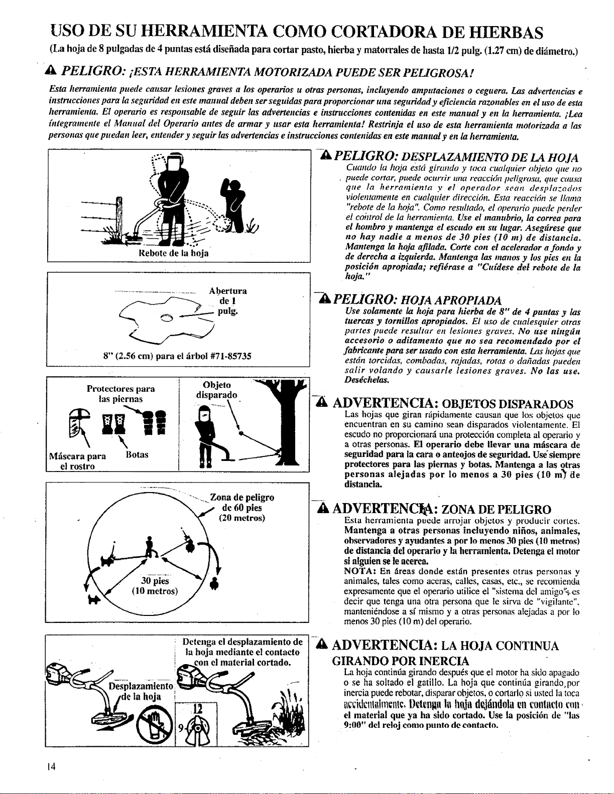
USO DE SU HERRAMIENTA COMO CORTADORA DE HIERBAS
(La hoja de 8 pulgadas de 4 puntas esld disefiada para cortar pasto, hierba y matorrales de hasta I/2 pulg. (1.27 cm) de di_imetro.)
A PELIGRO: iESTA HERRAMIENTA MOTORIZADA PUEDE SER PEL[GROSA!
Esta herramienta puede causar lesiones graves a los operarios u otras personas, incluyendo amputaciones o ceguera. Las advertencias e
instrucciones para Ia seguridad en este manual deben ser seguidas para proporcionar una seguridad y eficiencia razonables en el uso de esta
herramienta. El operario es responsable de seguir las advertencias e instrucciones contenidas en este manual yen ta herramienta, iLea
bztegramente el Manttal del Operario atttes de armar y usar esta herramienta! Restrinja el uso de esta herramienta motorizada alas
personas que puedan leer, entender y seguir las advertencias e instrucciones contenidas en este manual y en la herramienta.
Rebote de la hoja
........................ Abertura
pulg.
8" (2.56 cm) para el firbol #71-85735
Protectores para
tas piernas
Mfiseara para Botas
el rostro
......... Zona de peligro
de 60 pies
(20 metros)
la hoia
-A PELIGRO: DESPLAZAMIENTO DE LA HOJA
Cuando fa hoja e_'td girando y toca cualquier objeto que no
• pttede cortar, puede ocurrir una reaccida pel_qrosct, qtte causa
qae la herramienta y el operador seaa despla=ados
violentamente en cualquier direccMn. Esta reaccidn se llama
"rebote de la hoja'. Como restdtado, el operario imede perder
el cohtrol de la herramienta. Use el manubrio, la correct para
el hombro y mantenga el escudo en su lugar. Asegt_rese que
no hay nadie a menos de 30 pies (10 m) de distancia.
Mantenga la hoja afilada. Corte con el acelerador a fondo y
de dereeha a izquierda. Mantenga las maaos y los pies en la
posicidn apropiada; ref!#rase a "Caidese det rebote de la
hoja. "
PELIGRO: HOJA APROPtADA
Use solameute la hoja para hierba de 8" de 4 puntas y las
tuercas y tornillos apropiados. El uso de cualesqtder otras
partes puede resultar en lesiones graves. No use ningffn
accesorio o aditamento que no sea recomendado par el
fabrieante para ser usado con esta herram&nta. Las hojas que
estdn torcidas, combadas, rajadas, rotas o daffadas pueden
salir volando y causarle lesiones graves. No las use.
Des6chelas.
-A ADVERTENCIA: OBJETOSDISPARADOS
Las hojas que giran rfipidamente causan que los objetos que
encuentran en su camino sean disparados violentamente. El
escudo no proporcionard una protecci6n completa al operario y
a otras personas. El operario debe llevar una mdscara de
seguridad para la cara o anteojos de seguridad. Use'siempre
protectores para las piernas y botas. Mantenga alas otras
personas alejadas por lo menos a 30 pies (10 m_1 ite
distancia.
A ADVERTENCI : ZONA DE PELIGRO
Esta herramienta puede arrojar objetos y producir cortes.
Mantenga a otras personas incluyendo nifios, animales,
observadores y ayudantes a pot in menos 30 pies (10 metros)
de distancia del operario y la herramienta, Detenga el motor
si alguien se le acerea.
NOTA" En _reas donde esttin presentes otras personas y
animales, tales como aceras, calles, casas, etc., se recomienda
expresamente que el operario utilice et "sistema dcl am',go _,'cs
decir que tenga una otra persona que le sirra de v'gi!ante ,
manteni_ndose a sf mismo y aotras personas alejadas a pot Io
menos 30 pies (10 m) del operario.
Detenga el desplazamiento de
la hoja mediante el contacto
con el material cortado,
-A ADVERTENCIA: LA HOJA CONTINUA
GIRANDO POR INERCIA
La hoja continfia girando despu_s que el motor ha sido apagado
o se ha soltado el gatilto. La hoja que continfia girando por
inercia puede rebotar, disparar objetos, o cortarlc_ si usted la toca
uc_:idcnti_hncnt¢,D_.tcnguInhoja d_tind01acn contact0f:;_n,
el material que ya ha sldo cortado. Use la poslci6n de "las
9:00" del reloj como punto de contacto.
14
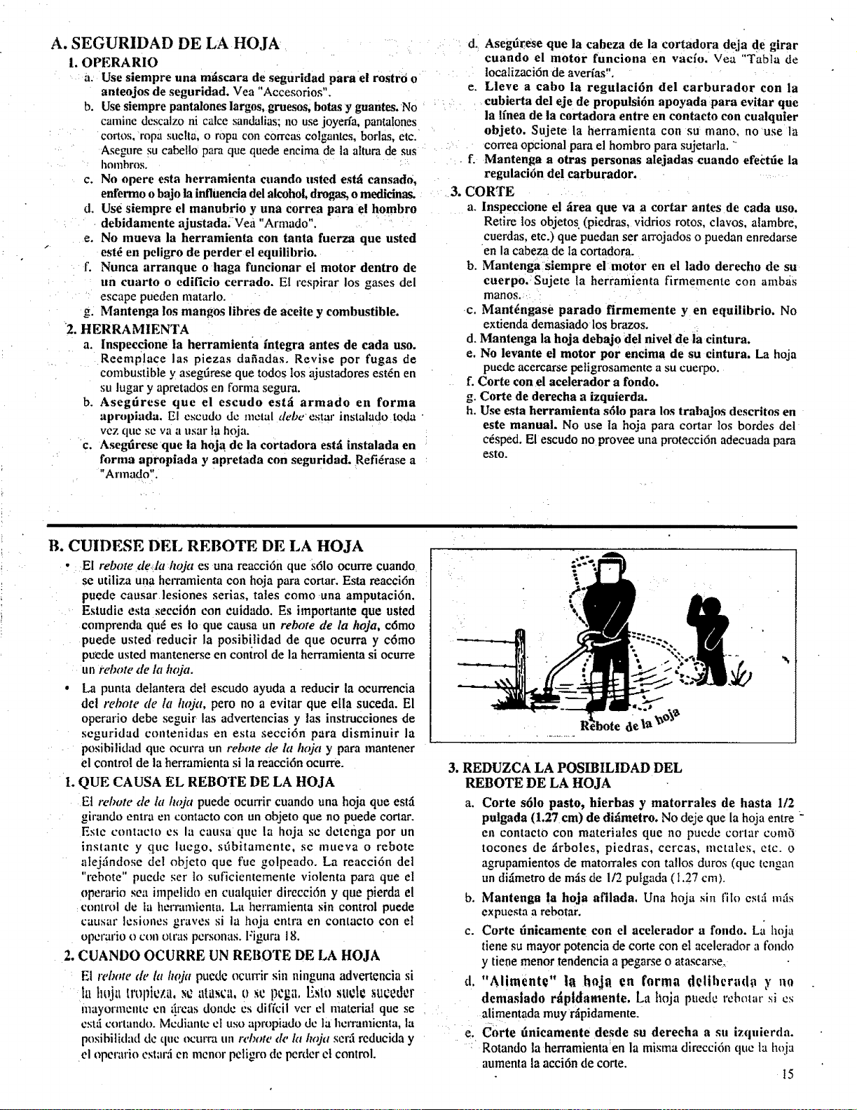
A. SEGURIDAD DE LA HOJA
i. OPERARIO
a. Use siempre una mfiscara de seguridad para el rostr0 o
anteojos de seguridad. Vea "Accesorios'k
b. Use siempre pantalones largos, gruesos, bolas y guantes. No
camine descalzo ni calce sandalias; no use joyefia, pantalones
cortos, ropa suella, o ropa con correas colgantes, borlas, etc.
Asegure su cabetlo para que quede encima de la altura de sus
homhros.
c. No opere esta herramienta cuando usted esth eansad0,
enfermo o bajo la influeneia del alcohol, drogas, o medicinas.
d. use siempre el manubrio y una correa para el hombro
debidamente ajustada.Vea "Armada".
e. No mueva la herramienta con tanta fuerza que usted
" est_ en peligro de perder el equilibria.
f. Nunca arranque o haga funcionar et motor dentro de
un cuarto o edificio cerrado. El respirar los gases del
escape pueden matarlo.
Mantenga los mangos lihres de aceite y combustible.
"2. HERRAMIENTA
a. lnspeccione la herramienia integra antes de eada usa.
Reemplace las piezas dafladas. Revise par fugas de
combustible y asegtirese que todos los ajustadores est6n en
su lugar y apretados en farina segura.
b. Asegtirese que el escudo est=i armada en farina
apropiada, El escudo de metal debeestar instalado toda
vez que se vaa usar ta h_ja.
c. Asegarese que la hoja de la cortadora est=l instalada en
forma apropiada y apretada con seguridad. Refi_rase a
"Armada".
d. Asegtlrese que la eabeza de la cortadora deja de girar
cuando el motor funciona en vac[o. Vea "Tabta de
tocalizaci6n de averfas".
e. Lleve a cabola regulaci6n del carburador con la
eubierta dei eje de propulsi6n apoyada para evitar que
la lfnea de la eortadora entre en contacto con cualquier
objeto. Sujete la herramienta con su mano, no use la
correa opcional para el hombro para sujetada. "
f. Mantenga a otras personas alejadas cuando efectde la
regulaci6n del earburador,
3, CARTE
a. Inspeecione el firea que va a cortar antes de cada usa.
Retire los objetos (piedras, vidrios rotos, clavos, alambre,
cuerdas, etc.) que puedan ser arrojados o puedan enredarse
en la cabeza de la cortadora.
b. Mantenga siempre el motor en el lado derecho de su
cuerpo.:Sujete la herramienta firmemente con amb_is
manos.
c. Mant_ngase parado firmemente yen equilibria. No
extienda demasiado los brazos. :.
d. Mantenga la hoja debajo del nivel de la cintura.
e. No levante el motor par encima de su cintura. La hoja
puede acercarse petigrosamente a su cuerpo.
f. Carte con el acelerador a fondo.
g. Carte de derecha a izquierda.
h. Use esta herramienta s61o para los trahajos descritos en
este manual. No use ta hoja para cortar los bordes del
c6sped. El escudo no provee una protecci6n adecuada para
esto.
B. CUIDESE DEL REBATE DE LA HOJA
• : El rebate de!In hojaes una reacci6n que s61o ocurre cuando
se utiliza una herramienta con hoja para cortar. Esta reacci6n
puede causar lesiones serias, tales coma una amputaci6n.
Estudie esta secci6n con euldado. Es importante que usted
comprenda qu_ es io que causa un rebate de la hoja, c6mo
puede usted reducir la posib[lidad de que ocurra y c6mo
puede usted mantenerse en control de la herramienta si ocurre
un i'ebote de la hoja.
• La punta delantera del escudo ayuda a reducir la ocurrencia
del rebate de la hoja, pero no a evitar que ella suceda. El
operario debe seguir las advertencias y las instrucciones de
seguridad contenidas en esta secci6n para disminuir la
posibilidad que ocm'ra un rebate tie la hoja y para mantener
el control de la herramienta si la reacci6n ocurre.
L QUE CAUSA EL REBATE DE LA HOJA
E1 rebate tie la hoja puede ocurrircuando una hoja que esui
girando entra en contacto con un objeto que no puede cortar.
Este contaclo cs la causa que la hoja sc detenga par un
_nstante y que luego, sdbitamente, se mueva o rebate
alej_indose del objeto que rue golpeado. La reacci6n del
"rebate" puede set to suficicntemente violenta para que el
operario sea impelido en cualquier direcci6n y que pierda el
control de la I_en'amienta. La herramienta sin control puede
causar Icsioncs graves si la hoja entra en contacto con el
opcrario o con otras personas. Figura 18,
2. CUANDO OCURRE UN REBATE DE LA HOJA
El rebow de la h@t pucdc ocurrir sin ninguna advertencia si
la ht_j_ttropicza, sc atasca, 0 sc pega. Esto sude suceder
mayormentc cn _ireas donde es diffcil vet el material que se
cstti cortando. Mcdiantc cl usa apropiado dc la hcrramicnta, la
posibilidad dc quc ocurra un rdn_te de kt hoja ser_i reducida y
el operario cstar;i en mcnor peligro de pealer cl control.
lul m,Li , i
3. REDUZCA LA POSIBILIDAD DEL
REBATE DE LA HOJA
a. Carte s61o pasta, hierbas y matorrales de hasta 1/2
pulgada (1.27 cm) de didmetro. No deje que la hoja entre :
en contacto con materiates que no puede tartar cam,3
tocones de _irboles, piedras, cercas, metalcs, etc. o
agrupamientos de mato_Tales con tallos duros (quc tengan
un di_imetro de m_s de 112 putgada ( 1.27 cm).
b. Mantenga la hoja afilada. Una hoja sin ilia est_ m_is
expuesta a rebotar.
c. Corte finicamente con el acelerador a fondo. Ltl hoja
tiene su mayor potencia de corte con el acelerador a rondo
y tiene menor tendencia a pegarse o atascarse,
d. "Aliments" hi hoja en farina delihcra(ha y no
demaslado r_tptdamente, La hoja puedc rcbotat" si cs
alimentada muy r_ipidamente.
e. Carte tlnicamente desde su dereeha a su izquierda.
: Rotando la herramienta_en la misma direcci6n que la hoja
aumenta la acci6n de cone.
15
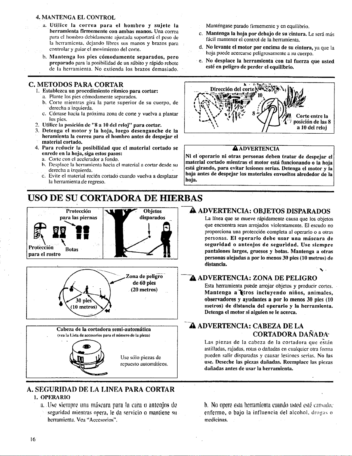
4. MANTENGA EL CONTROL
a. Utilice la correa para el hombro y sujete la
herramienta firmemente con ambas manos. Una correa
para cl hombro debidamcntc ajustada soportar;i el peso de
hi hcrranfienta, dejando libres sus manos y brazos para
controlar y guiar el movimiento del corte,
b. Mantenga los pies c6modamente separados, pero
preparado para la posibilidad de un sfibit0 y rfipido reb0te
de la herramienta, No extienda los brazos demasiado.
C. METODOS PARA CORTAR
t. Establezca un proeedimiento ritmieo para cortar:
a. Plante los pies c6modamente separados.
b. Corte mientras gira la parte superior de su cuerpo, de
derecha a izquierda.
c. C6rrase hacia la prdxima zona de come y vuelva a plantar
los pies.
2. Utilice la plmlci6n de "8 a 10 del reioj" para cortar.
3. Detenga el motor y la hoja, luego desenganehe de la
heramlenla la eorrea para el hombro anies de despejar el
material cortado.
4. Para reducir la posibilidad que el material cortado se
enrede en la hoja, siga estos pasos:
a. Corle con el acelerador a lkmdo.
h, Desplace la herramienm hacia el material a cortar desde su
derecha a izquierda.
c. Evite el material reci6n eortad0 cuando vuelva a desplazar
la herramienta de regreso.
Mant6ngase parado firmemente yen equilibrio.
c. Mantenga la hoja por debajo de su ¢intura. Le serfi mils
fficil mantener el control de la herramienta,
d, No ievante el motor por encima de su cintura, ya que la
hoja puede acercarse peligrosamenle a su cuerpo.
e. No desplace la herramienta Con tal fuerza que usted
est6 en peligro de perder el equilibrio,
J L
-k !.
Direcci6n del corte
Corte entre la
t_.-. _"/posicidn de las 8
" a I0 del reloj
A"ADVERTENCIA I
Ni el operario ni otras personas deben tratar de despejar el I
material cortado mientras el motor estfi funcionando o ia hoja I
[esr.i girando, para evitar lesiones serias. Detenga el motor y la]
[ hoja antes de despejar los materiales envueltos alrededor de ia J
Ih*" t
H i i i t
USO DE SU CORTADORA DE HIERBAS
Protecci6n
para las piernas
m@ m!l
}ara el rostro
Objetos
disparados
Cabeza deia cortadora semi.autom'.Itiea
(yea la Li._|a de accesorios para el nfimero de la p|eza)
Use s61o piezas de
repuesto automziticos.
A ADVERTENCIA: OBJETOS DISPARADOS
La lfnea que se mueve r,4pidamente causa que los objetos
que encuentra sean arrojados viotentamente. Et escudo no
proporciona una proteeci6n completa al operario o a otras
personas. E! operario debe usar una m_iseara de
segurldad o anteojos de segu_dad. Use siempre
pantalones largos, gruesos y botas. Mantenga a otras
personas alejadas a pot lo menos 30 pies (10 metros) de
distaneia.
ADVERTENCIA: ZONA DE PELIGRO
Esta herramienta puede arrojar objetos y producir cortes.
Mantenga alLtros incluyendo nifios, animales,
observadores y ayudantes a por lo menos 30 pies (I0
metros) de dlstanc|a del operar|o y la herram|enta,
Detenga el motor si alguien se le acerca.
ADVERTENCIA: CABEZA DE LA
CORTADORA DAlqADA"
Las piezas de la cabeza de la cortadora que eslfin
asiitladas, rajadas, rotas o dafiadas en cualquicr otra forma
pueden said disparadas y causar lesiones serias. No las
use. Deseche las piezas dafiadas. Reemplace tas piezas
dafiadas antes de usar la herramienta.
A. SEGURIDAD DE LA LINEA PARA CORTAR
1. OPERARIO
tl. [J._L?_b2111111'_t.1!11tlllil_t2lll;ll ptlrtl ]i| ctlrll 0 tllllt?Ojll_ d0
seguridad mientras opera, 1€da servicio o mantien¢ su
htrrral|liellla. Vea "Accesorios".
b, No Oltl_l't_0,_Ill hl}rl'alllit}llltl tXlttlldo tlsletl exl_ c'illl_iltltk
enfermo, o bajo la inf!uencia del alcohol, drogas o
medicinas.
16
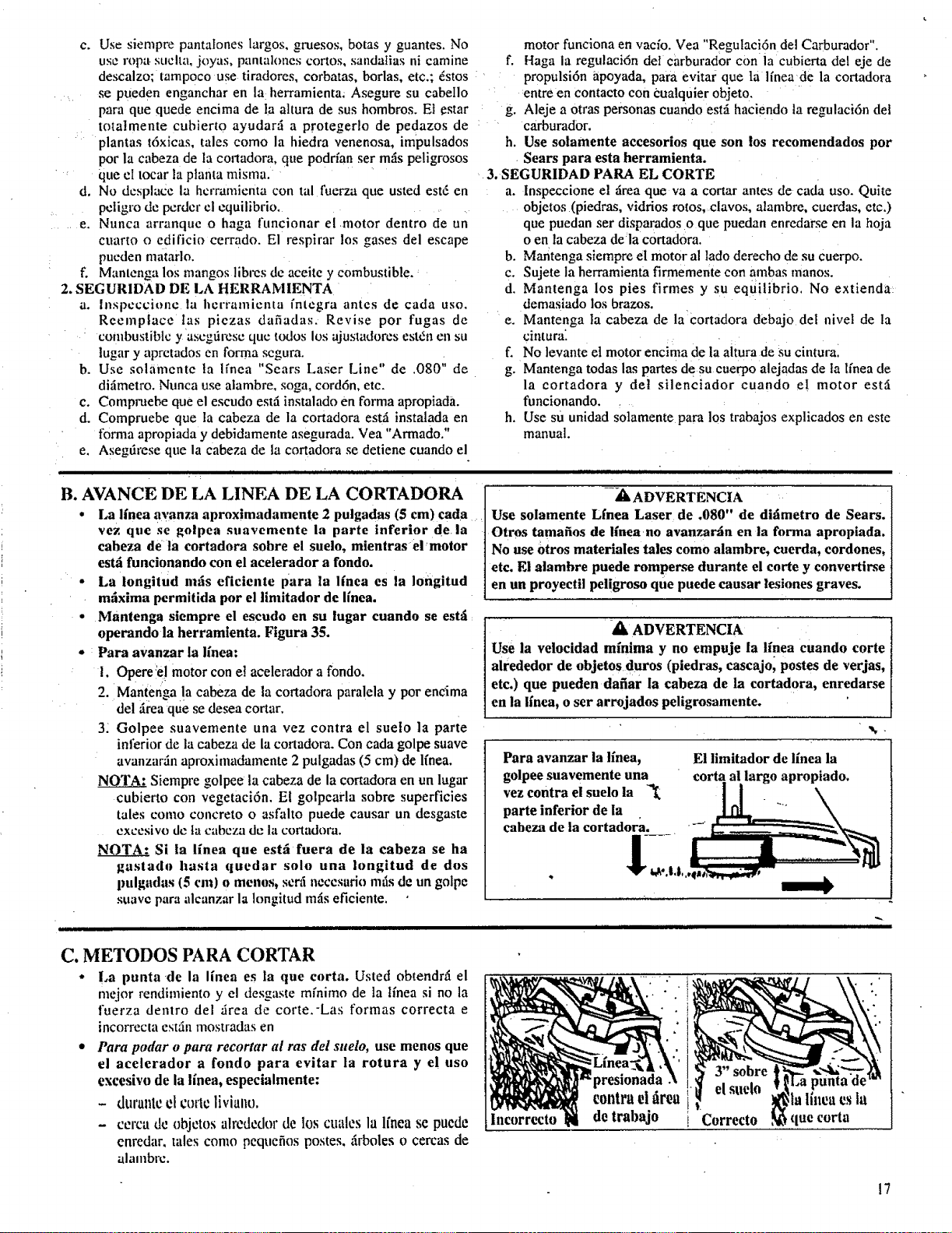
c. Usesiemprepantatoneslargos,gmesos,botasy guantes.No
useropa.suclta,joyas,pantalonescortos,sandatiasnicamine
descalzo;tamP0cousetiradores,corbatas,borlas,etc.;_stos
sepuedenengancharenla herramienta_Aseguresucabello
paraquequedeencimadelaatturadesushombros.Et€star
totatmentecubiertoayudarila protegerlodepedazosde
plantast6xicas,talescomola hiedravenenosa,impulsados
potlacabezadelacortadora,quepoddansermilspeligrosos
queeItocarIsplantamisma.
Nodcsplacela hcrramicntacontalfuerzaqueustedest6en
pctigrodepcrdcrclcquilibrio.....
Nuncaarranquco hagaftmcionarelmotordentrodeun
cuartoo edificiocerrado.Elrespirarlosgasesdelescape
puedenmatarlo.
f. Mantengalosmangoslibresdeaceiteycombustible.
2.SEGURIDADDEI,,AHERRAMIENTA
a. lnspcccioJ_c la herramienta fntcgra antes de cada uso.
Reemplace Ins piezas dafiadas. Revise por fugas de
combustible y ascgtircsc quc todos los ajustadores estdn en su
tugar y apretados en forma segura.
b. Use solamente ta lfnea "Sears Laser Line" de .080" de
difimetro. Nunca use alambre, soga, cord6n, etc.
e. Compruebe que el escudo estfi instalado en forma apropiada.
d. Compruebe que la cabeza de la cortadora estil instalada en
forma apropiada y debidamente asegumda. Vea "Armado."
e, Asegtirese que la cabeza de la cortadora se detiene cuando el
d.
..... e.
motor funciona en vacfo. Yea "Regulaci6n del Carburador".
f. Haga la regulaci6n del carburador con la cubierta del eje de
: ' propulsi6n apoyada, para evitar que ta linende la cortadora
:entre en contacto con cualquier objeto.
g. Aleje a 0tras personas cuando estfi haciendo ta regulaci6n del
: carburad0r.
h. Use solamente accesorios que son los recomendados por
Sears para esta herramienta.
3. SEGURIDAD PARA EL CORTE
a. inspeccione el firea queva a cortar antes de cada uso. Quite
objetos (piedras, vidrios rotos, clavos, alambre, cuerdas, etc,)
que puedan set disparados o que puedan enredarse en la hoja
o en la cabeza de/a cortadora.
b. Mantenga siempre el motor al lado derecho de su cuerpo.
c. Sujete la herramienta firmemente con ambas manos.
d. Mantenga los pies firmes y su equilibrio. No extienda
demasiado los brazos.
e. Mantenga la cabeza de la cortadora debajo del nivel de la
cintura:
f. No levante el motor encima de la aitura de su cintural
g. Mantenga todas las partes de su euerpo alejadas de ta Ifnea de
la cortadora y de! silenciador cuando e! motor est,5
funcionando ....
h. Use su unidad solamente para los trabajos explicados en este
manual.
B. AVANCE DE LA LINEA DE LA CORTADORA
• La linea avanza aproximadamente 2 pulgadas (5 cm) eada
vez que se golpea snavemente la parle inferior de la
eaheza de la cortadora sobre el sueio, mientras el'motor
estfi funcionando con el acelerador a rondo.
• La longitud mils eficiente para la linea es la Iongitud
mfixima permitida pot el limitador de ffnea.
-_1_ ADVERTENCIA
Use solamente Lfnea Laser de .080" de difimetro de Sears.
Otros tamafios de ffnea no avanzar_in en la forma apropiada.
No ase 0tros materiales tales como alambre, caerda, cordones,
etc. El alambre puede romperse durante el corte y eonvertirse
en un proyectil peligroso que puede causar leslones graves.
Mantenga siempre el escudo en su lugar cuando se esth
operando la herramienta. Figura 35. _ih ADVERTENCIA
Para avanzar la linea: use la velocidad minima y no empuje la l[nea cuando corte
!. Opere_el motor con et acelerador a rondo, alrededor de objetos duros (piedras, cascajo, postes de verjas,
etc.) que pueden dafiar la cabeza de la cortad0ra, enredarse
2. iMantengadel_ireaque!asecabezadeseadecortar.lacortadora para!ela y por encima ] en la linen, o ser arrojados peligrosamente.
31 Golpee suavemente una vez contra el suelo la parte
inferior de la cabeza de la cortadora. Con cada golpe suave
avanzarAn aproximadamente 2 pulgadas (5 cm) de lfnea.
N_N_Q.TAI:Siempre golpee la cabeza de la cortadora en un lugar
cubierto con vegetaci6n. El golpearla sobre superficies
tales como concreto o asfalto puede causar un desgaste
cxccsivo de ta cabeza de la coaadora.
NOTA: Si la linea que est_i fuera de la cabeza se ha
gastado hasta quedar solo una Iongitud de dos
pulgadas (5 cm) o menos, serli ncccsado mils de un golpe
suave para alcanzar la Iongitud mils eficiente.
Para avanzar la llnea,
golpee suavemente una
vez contra el suelo la
parte inferior de la
eabeza de la cortadora.
!2
El limitador de llnea la
corta al largo apropiado.
C. METODOS PARA CORTAR
• La punta de la linen es la que corta. Usted obtendrfi el
mejor rendimiento y el desgaste mfnimo de la tfnea si no la
fuerza dentro del Area de corte.-Las formas correcta e
incorrecta est5,_ mostradas en
• Para podar o para recortar al ras del suelo, use menos que
el acelerador a rondo para evitar la rotura y el uso
excesivo de la linea, especialmente:
- dttral_tCel c_>rlcliviano,
- cerca de objetos alrededor de los cuales la linen se puede
enredar, tales como pequefios postes+ ilrboles o cercas de
alalnbrc.
lncorreeto
presionada
contrael firea
de trabajo
el suelo
la linen es ia
[ Correcto que corta
!7
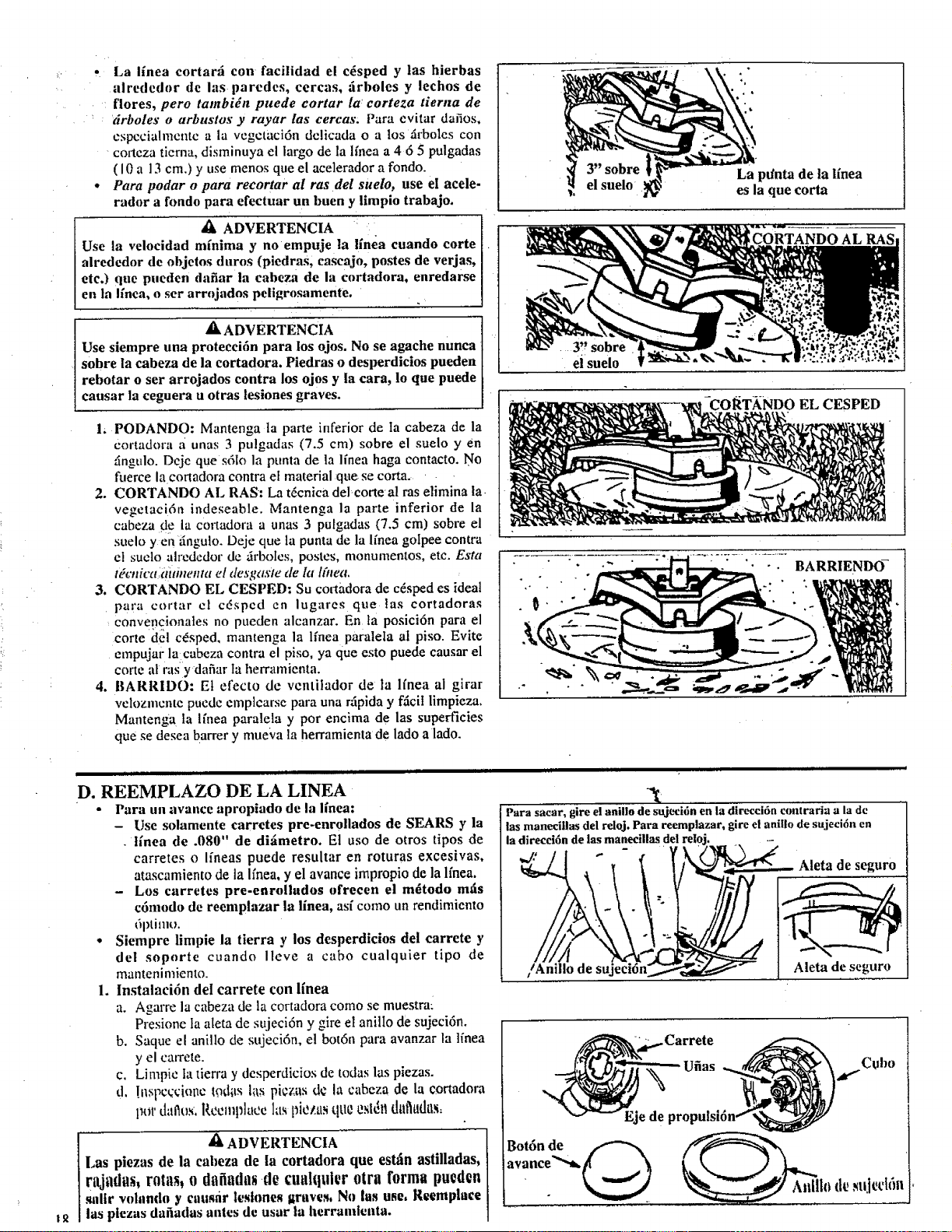
La iinea cortar_i con facilidad el c_sped y las hierbas
alrededor de las paredes, cercas, :irboles y lechos de
flores, pero tambi_n puede cortar la: corteza tierna de
drboles o arbustos y rayar las cercas. Para evitar daiios,
cspccialmcntc a la vcgctaci6n delicada o a los _irboles con
corteza tierna, disminuya el largo de la lfnea a 4 6 5 pulgadas
( 10 a 13 cm.) y use menos que el acelerador a rondo.
Para podar o para recortar al ras del suelo, use el acele-
rador a fondo para efectuar un buen y limpio trabajo.
,1_ ADVERTENCIA :
Use la velocidad minima y no empuje la linea cuando corte
alrededor de objetos duros (piedras, cascajo, postes de verjas,
etc.) que pueden dafiar la cabeza de la eortadora, enredarse
en la linea, o ser arrojados peligrosamente.
_, ADVERTENCIA
Use siempre una protecci6n para los ojos. No se agache nunca
sobre la cabeza de la cortadora. Piedras o desperdicios pueden
rebotar o ser arrojados contra los ojos y la cara, 1o que puede
causar la ceguera u otras lesiones graves.
1, PODANDO: Mantenga la parte inferior de ta cabeza de la
cortadora a unas 3 pulgadas (7.5 cm) sobre el suelo y en
_ngulo. Deje que s61o la punta de la Ifnea haga contacto. No
fuerce la conadora contra et material qae se corta.
2. CORTANDO AL RAS: La tdcnica del_corteal ras elimina la
vegetaci6n indeseable, Mantenga la parte inferior de la
cabeza de la cortadora a unas 3 pulgadas (7.5 cm) sobre el
suelo y en zingulo. Deje que la punta de la li'nea golpee contra
el suclo ah'edcdor de _rboles, postes, monumentos, etc. Esta
t_cnica aithtenta el desgasie de la Ifttea.
3. CORTANDO EL CESPED: Su coaadora de cdsped es ideal
para cortar el cdsped cn lugares que las eortadoras
convencionales no pueden alcanzar. En la posici6n para el
corte del cdsped, mantenga la lfnea paratela al piso. Evite
empujar la_cabeza contra el piso, ya que esto puede eausar el
eorte al ras y dafiar ta herramienta.
4. BARRIDO: El efecto de ventilador de Ia lfnea al girar
velozmente puede emplearse para una r@ida y fficil limpieza.
Mantenga la Ifnea paralela y por encima de las superficies
que se desea barrer y mue;va la herramienta de lado a lado.
• +
el suelo
La pdnta de ta llnea
es la que corta
....3" sobre
ei suelo
EL CESPED
BARRIENDO-
t_
nj pin ir i1,1 i nil illU
D. REEMPLAZO DE LA LINEA
• Para un avance apropiado de la linea:
- Use solamente earretes pre-enroIlados de SEARS y la
linea de .080" de difimetro. El uso de otros tipos de
carretes o Ifneas puede resultar en roturas exeesivas,
atascamiento de la Ifnea, y el avance impropio de la lfnea,
- Los carretes pre-enrollados ofrecen el m_todo mtis
c6modo de reemplazar la linea, asi como un rendimiento
6ptimt_.
• Siempre limpie la tierra y los desperdicios del carrete y
del soporte cuando Ileve a cabo cualquier tipo de
mantenimiento.
1. lnstalaci6n det carrete con l[nea
a. Agarre la cabeza de la cortadora como se muestrai
Presione ta ateta de sujeci6n y gire el anillo de sujeci6n.
b. Saque el anillo de sujeci6n, el bot6n para avanzar la ]inea
y el earrete.
c. Limpie la tierra y desperdicios de todas las piezas.
d, !nspc¢ciol_e lodlts las picz_asde la cabeza de la ¢onadom
potdaftos. Recmplace las t_ieztlstlUt_Csl_l_dal'tudas:
ADVERTENCIA
Las piezas de la cabeza de la cortadora que est_in astilladas,
rajtldus, r0t_ls_ 0 dt_fiadas de cualquler 0tra form pued0n
salir volando y causdr iestones graves, No las use, Reemphtce
las plezas daiiadas antes de usar la herramlenta.
Para sacar, gire el anillo de sujecidn en 12 direccl6n contraria a la de
las manecUlas del reloj. Para reemplazar, gire el anillo de sujecidn en
la direccidn de las manecillas del
Aleta de seguro
/Anillo de su Aleta de seguro
' K "Carrete
Ufias ,_ Cubo
Eje de propulsldn ._'
Bot6n de _ __,
avance'__
• _ It_d_ _uiet'16n
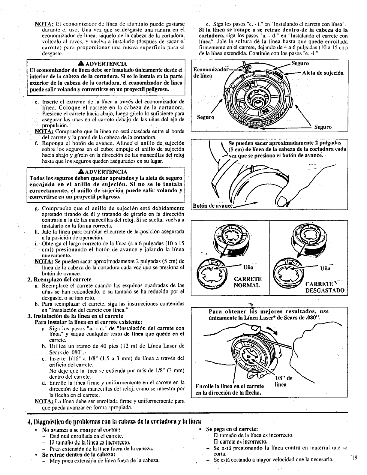
N_OTA.: El economizador de Ifnea de atuminio puede gastarse
durante el uso. Una vez que se desgaste una ranura en el
economizador de Ifnea, sfique[o de [a cabeza de la cortadora,
voltdelo a! rev6s, y vuelva a instalarlo (despuds de sacar el
carrete) para proporcionar t,na nueva superficie para el
desgaste.
ZI, ADVERTENCIA
El economizador de linea debe ser instalado tinicamente desde el
interior de la cabeza de ia cortadora. Si se lo instala en la parte
exterior de la cabeza de Ia cortadora, el economizador de linea
puede salir volando y convertirse en un proyectil peligroso.
e. [nserte el extremo de la lfnea a travds del economizador de
Ifnea. Coloque el carrete en la cabeza de la cortadora.
Presione el carrete hacia abajo, luego gfi_elo Io suficiente para
asegurar las ufias en el carrete dcbajo de las ufias del eje de
propulsi6n.
NOTA: Compruebe que la lfnea no estzi atascada entre el borde
del carrete y la pared de la cabeza de la cortadora.
f. Reponga el bot6n de avance. Alinee el anillo de sujeci6n
sobre los seguros en el cubo; empuje et anillo de sujeci6n
hacia abajo y gfrelo en la direcci6n de las manecillas de! reloj
hasta que los seguros queden asegurados en su lugar.
A A D VERTENCIA
Todos los seguros dehen quedar apretados y la aleta de seguro
encajada en el anillo de sujeci6n, Si no se 1o instala
correctamente, el anillo de sujeci6n puede salir volando y
convertirse en un proyectil peligroso.
g. Compruebe que el anillo de sujeei6n est_f debidamente
apretado tirando de _I y tratando de girarlo en ta direcci6n
contraria a la de tas manecillas del reloj. Si se suelta, vuelva a
instatarfo en la forma correcta.
h. Jale la linea para cambiar el carrete de la posici6n asegurada
a la posici6n de opcraci6n.
i. Obtenga el largo correcto de la Ifnea (4 a 6 pulgadas [10 a 15
cml) presionando el bot6n de avance y jalando la Ifnea
iltlevatllettle.
Sept, eden sacar aproximadamente 2 pulgadas (5 cm) de
l/nea de la cabeza de In cormdora cada vez que se presiona el
bot6n de avance.
2, Reemptazo del carrete
a. Reemplace el carrete cuando las esquinas cuadradas de las
ufias se han redondeado, o su tamafio se ha reducido por el
desgaste, o se ban roto.
b. Para reemplazar el carrete, siga las instrucciones contenidas
en "Instalaci6n del carrete con linea."
3, lnstalaci6n de la lfnea en el carrete
Para instalar la linen en el carrete existente:
a. Siga los pasos "a. - d." de "lnstalaei6n del carrete con
Itnea" y saque eualquler re_to d_ Ifnea que quodo en et
carrete.
b. Utilice un tramo de 40 pies (12 m) de Lfnea Laser de
Sears de .080"..
c. lnserte 1116" a 1/8" (I.5 a 3 mm) de Ifnea a travds del
orificlo del carrete.
No deje qt, e la Ifnea se exlienda por ross de 118" (3 ram)
dentro dcl carrete.
d. Enrotle la Ifnea firme y t,nifornlemente en el carrete en la
dirccci6n de las manccillas del reloj, como se muestra por
la tlecha en el can'ete.
NOTA: La I[nea debe ser enrotlada firme y uniformemente para
que pueda avanzar en forma apropiada.
IIIII 11 I I 11111 I111
4, I)iit!In6 lit: prolfl ma t:on la ortad0n y la
• No avanza o se rompe al coring: o
- Estzi real enrollada en el carrete.
- Poca cxtensi6n tie ta Ifnea fuera de lu cabeza.
• Se retrae dentro de la cabeza:
- Muy poca extensi6n de Ifnea fuera de la ¢abeza,
e. Siga los pasos "e. - i." en "tnstalando el can'ete con lfnea",
Si la linen se rompe o se retrae dentro de la cabeza de la
cortadora, siga los pasos "a. - d." en "Instalando el carrete con
Ifnea". Jale la soltura de la I[nea hasta que quede enrollada
firmemente en el carrete, dejando de 4 a 6 pulgadas ( I0 a 15 cm)
de Ia Ifnea extendida, Contintle con los pasos "e. -i."
Seguro
e sujeci6n
Seguro
| I Se pueden sacar aproximadamente 2 pulgadas
\ _(5 era) de iinea de la cabeza de la cortadora cada
\ ,_vez que se presionael bot6n de avance,
o
Bot n
_ CARRETE _/-
DESGASTADO
Para obtener 16s mejores resuttados, use
finieamente la Linen Laser e de Sears de .080".
1/8" de
linea
Enrolle la linea en el carrete
en la direcci6n de la flecha.
Se pega en el carrete:
- El tamafio de la tfnea es incorrecto.
- I_1carret¢ €,_in¢0_xect0,
- S¢ est;t presionando la Ifnea contr.'t ct_ materlal que se
eorta;
-. Se estfi cortando a mayor velocidad que la necesaria.
"19

roll IIIIIIIIIIIIII IIII II I IIIIIIII IIIII IIIII I I I IIIII I IIII
ACCESORIOS
Ill I I' I Illllll II I Illll Illl Illl II
Los siguientes acceso,'ios est_in disponibles a tray,s de Ias tiendas al detalle, oficinas para pedidos por cat_il0go y centros de servicio
de Sears:
ITEM NUMERO DE PIEZA
M_iscara de seguridad para la cara ....................................................................... ...................................................................... 9-18613
Anteojos de seguridad .................................................................................................................................................................... 9-1859
Aceite para motor de 2 tiempos ................................ .. ............................................................................................................... 71-30t43
Bujfa., ......................................................................... ;........................................................................ :....................................... 71-85854
Hoja para hierba de repuesto ...................................................................................... ..................... ;........................................ 71.85735
Cabeza de la cortadora de repuesto (disponible s61o a trav6s de los centros de servicio Sears) ..................................... 530-094604
Linen de nylon de 0.80" diam. de repuesto para la cortadora
- 400 pies (122 m) .................................................................................................................................................................. 71-85778
- 200 pies (61 m) .................................................................................................................................................................... 71-85608
- 100 pies (31 m) .................................................................................................................................................................... 71-85771
Carrete de repuesto con linen .................................................................................................................................................... 71.85815
Equipo de correa para el hombro ............................................................................................................................................. 71-85783
Equipo de paraehispas ................... _.................................................................................................. ............................... ,...952-701612*
Lubricante para el'eje flexible ........................ ;.................................................................................................................... 530-030102*
*Disponihle a tray,s de su ¢entro de serviclo/catfitogo SEARS.
2O
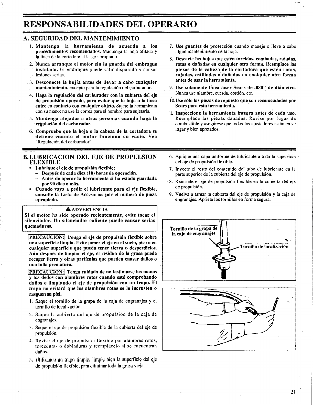
ill " II IJIIIIIIII II I I I I
RESPONSABILIDADES DEL OPERARIO
Illllll Illlllllllll II I lll L I lllll Illl I I II Ill I I Ill Ill I II Illl Ill l I llllll Ill Illll II I I
A. SEGURIDAD DEL MANTENIMIE_<TO
[. Mantenga ia herramienta de acuerdo a los 7,
procedimientos recomendados. Mantenga la hoja afilada y
la lfilca de la uortadora al largo apropiado. 8.
2. Nunca arranque el motor sin la guarda del embrague
instalada, El embrague puede salir disparado y causar
lesiones serias.
3. Desconecte la bujfa antes de llevar a cabo eualquier
mantenimiento, excepto para la regulaci6n del carburador.
4. Haga la regulaci6n de| carburador con la cubierta del eje
de propulsi6n apoyado, para evitar que la hoja o la linea
entre en contacto con cualquier objeto. Sujete la herramienta
con su mano; no use la correa para el hombro para sujetarta.
5. Mantenga alejadas a otras personas cuando haga la
regulaeifn del earburador,
6, Compruebe que la hoja o la eabeza de la eortadora se
detiene euando el motor funeiona en vae[o, Vea
"Regulaci6n del carburador".
IIIIIIIIIIIII IIIIIIIIIIIIIIIIIIIIIIIIIIIIIqlIIIIII IIIIIIIIIIIIIII I II IIIII
Use guantes de protecci6n cuando maneje o lleve a cabo
algdn mantenimiento de la hoja.
Descarte las hojas que est6n torcidas, combadas, rajadas,
rotas o dafiadas en cualquier otra forma. Reemplace las
piezas de la cabeza de la cortadora que est_n rotas,
rajadas, astilladas o dafiadas en cuatquier otra forma
antes de usar la herramienta,
9. Use solamente lfnea laser Sears de .080" de difimetro,
Nunca use alambre, cuerda, cord6n,etc.
10,Use sdlo las piezas de repuesto que son recomendadas pot
Sears para esta herramienta.
I1. Inspeecione la herramienta fntegra antes de cada uso,
Reemplace las piezas dafiadas, Revise pot fugas de
combustible y aseggrese que todos los ajustadores estfin en su
lugar y bien apretados.
B.LUBRICACION DEL EJE DE PROPULSION
FLEXIBLE
° l.ubrique el eje de propulsi6n flexible:
- Despu_s de cada diez (10) horas de operaci6n.
- Antes de operar ia herramienta si ha estado guardada
por 90 dias o mils.
• Cuando vaya a pedir el lubrieante para el eje flexible,
eonsulte la Lista de Accesorios por el nfimero de pieza
apropiado.
_, ADVERTENCIA
Si el motor ha sido operado recientemente, evite tocar el
silenciador. Un silenciador caliente puede causar serias
quemaduras.
tI'RECAUCION:] Ponga el eje de propulsi6n flexible sobre
una superficie limpia. Evite porter el eje en el suelo, piso o en
cualquier superficie que pueda tener tierra o desperdicios.
Afin despu_s de iimplar el eje, el residuo de la grasa puede
recoger tierra y otras parffculas que pueden eausar dafios o
una falla prematura.
{PRECAUC1ON: I Tenga cuidado de no lastimarse las manos
y los dedos con alambres rotos euando est_ comprobando
dafios o limpiando el eje de propulsidn con un trapo. El
trapo no evitarfi que los alambres rotos se le incrusten o
rasguen su ptel.
I. Saque el tornillo de la grapa de la caja de engranajes y el
tomilto de localizaci6n.
2. Saque la cubierta del eje de propulsi6n de la caja de
efl_l ,Irl dJ,-2s.
3. Saque el ejc de propulsi6n flexible de la cubierta del eje de
propulsi6n.
4, Revise cl cjc de proputsi6n flexible pot alambres rotos,
torceduras o dobkrduras y reemplgcelo si se encuentran
da_os.
I._lili_.iu_d__u lri_p0,linqi , limpi hienla ,_upcrfi¢i¢ d¢l eje
de propulsi6n Ilcxiblc, para eliminar toda la grasa vleja.
6.
7:
8.
9.
Aptique una capa uniforme de Iubricante a toda la superficie
del eje de propulsi6n flexible.
lnyecte el resto del contenido del tubo de lubricante en la
parte superior de la cubierta del eje de propulsi6n.
Reinstale el eje de propulsi6n flexible en la cubierta del eje
de propulsi6n.
Vuelva a armar la cubierta del eje de propulsi6n y la caja de
engranajes. Apriete los tornillos en forma segura.
;rornillo de la grapa de
la caja de engranajes
Tornillo de iocalizaci6n
21
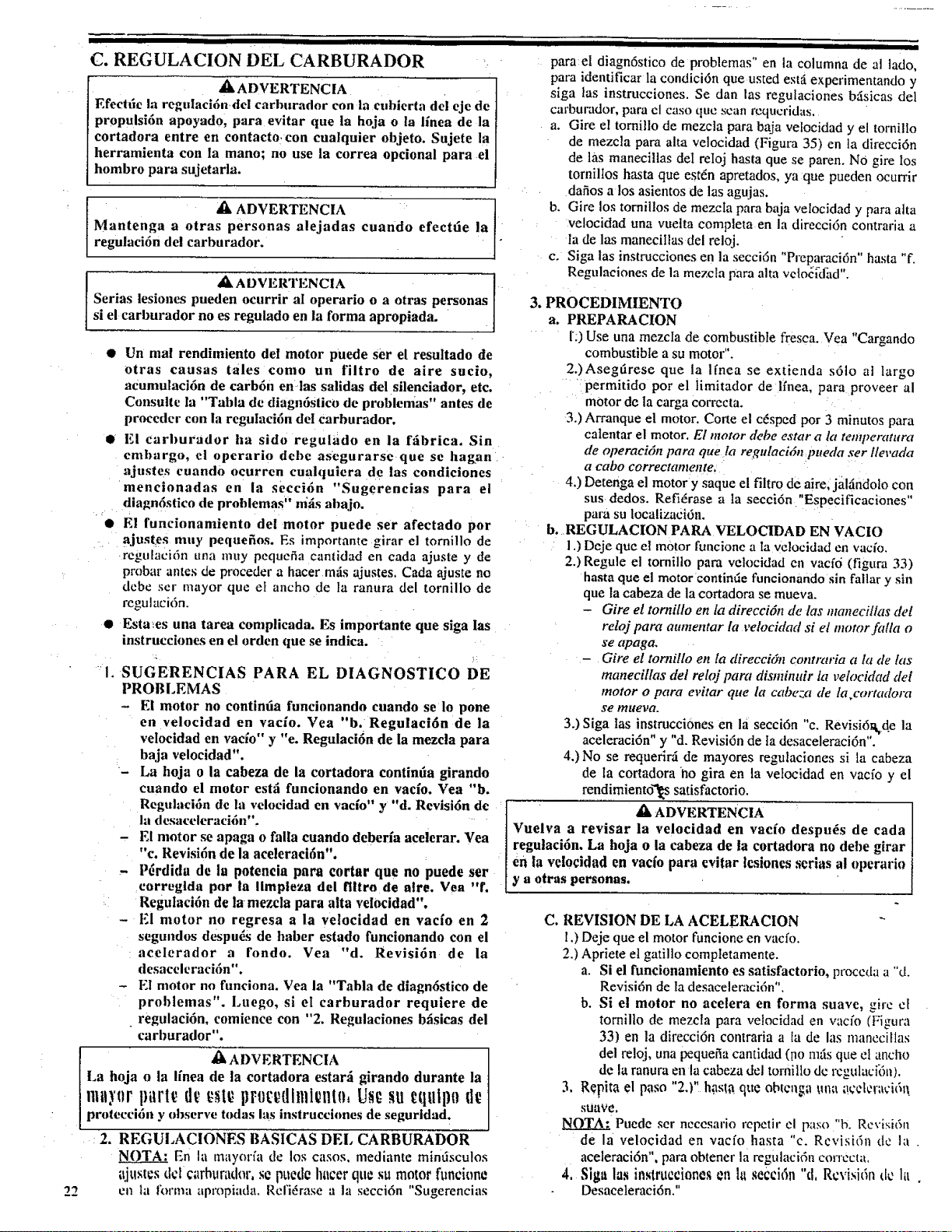
22
I I II I I Ill I
DEL
C. REGULACION CARBURADOR
,[k ADVERTENCIA
Electric la regulaci6ndel carburador con la eublerta de l eje de
propulsi6n apoyado, para evitar que la hoja o la lfnea de la
cortadora entre en eontacto con cualquier objeto. Sujete la
herramienta con la mano; no use la correa optional para el
hombro para sujetarla.
_k ADVERTENCIA
Mantenga a otras personas alejadas cuando efectde la
regulaci6n del carburador.
a_ ADVERTENCIA
Serias lesiones pueden ocurrir al operario o a otras personas
si el carlmrador no es regulado en la forma apropiada.
• Un real rendimiento del motor puede ser el resultado de
otras causas tales como un filtro de aire sue!o,
acumulaci6n de carb6n en/as salidas del silenciador, etc.
Consulte la "Tabla de diagn6s|ico de problenms" antes de
proceder con la regulaci6n del carburador.
• El carburador ha sido regulado en la ftibrica. Sin
embargo, el operario debe asegurarse que se hagan
ajustes cuando ocurren cuahluiera de !as condiciones
meneionadas en la secci6n "Sugerencias para el
dlagn6stico de problemas" ni_s abajo.
L
• El funeionamiento del motor puede set afectado por
4
r
_jUstdes
muy peqnefios. Es importante girar el tornillo de
regu[aci6n una muy pequefia cant!dad en cada ajuste y de
probar antes de proceder a hater mtis ajustes. Cada ajus_e no
debe ser mayor que et ancho de la ranura del tornillo de
regul aci6n.
• Esta:es una tarea complicada. Es importante que siga !as
instruct!ones en el orden que se indica.
SUGELRENCIAS PARA EL DIAGNOSTICO DE
PROBLEMAS
- El motor no continda funcionando euando se 1o pone
en velocidad en vaefo. Vea "b. Regulaci6n de la
velocidad en vacfo" y "e. Regulaci6n de la mezela para
baja velocidad".
- La hoja o la cabeza de la cortadora continda girando
cuando el motor est_ funcionando en vac[o. Vea "b.
Regulaci6n de la velocidad en vac[o" y "d. Revlsi6n de
la desaceleraci6n".
- El motor se apaga o falla cuando deberfa aceierar. Vea
"c. Revisi6n de la aceleraci6n".
- P_rdida de la potencia para cortar que no puede ser
eorreglda pot la llmpleza del [litro de alre. Vea "f.
Regutaci6n de la mezcla para alta velocidad".
- F.l motor no regresa a la velocidad en vacfo en 2
segundos despu_s de haber es{ado funcionando con el
acelerador a rondo. Vea "d. Revisi6n de la
desaceleraci6n".
- E1 motor no fimciona. Vea la "Tabla de diagn6stico de
problemas". Luego, si el carburador requiere de
regulaci6n, comience con "2. Regulaciones bfisieas del
carburador".
_[k ADVERTENCIA
La hoja o la ffnea de la cortadora estard girando durante la
proteeci6n y observe todas las instruct!ones de seguridad.
: 2. REGULACIONES BASICAS DEL CARBURADOR
NOTA: En la mayor_a de los casos, mediante mindsculos
ajustcs d¢l ¢arhurador, s¢ puede hater qu¢ su motor funcione
en la forma apropiada, Rcfi6rase a la secci6n "Sugerencias
I I II
para el diagn6stico de problemas" en la columna de al tado,
para identificar la condici6n que usted estfi, experimentando y
siga las instrucciones. Se dan las regutaciones bfi.sicas del
carburador, para cl caso que scan l'cqucridas,
a. Gire eZ tornillo de mezcla para baja velocidad y el tornillo
de mezcla para alta velocidad (Figura 35) en la direcci6n
de las manecillas deI reIoj hasta que se paten. NO gire los
torniltos hasta que est_n apretados, ya que pueden ocurrir
dafios a los asientos de las agujas.
b. Gire los tornil!os de mezeIa para baja velocidad y para alta
ve!ocidad una vuelta completa en la direeci6n contraria a
la de las maneciIlas del reloj.
e. Siga las instrueciones en la secci6n "P,'eparaci6n" hasta "f.
Regulaciones de la mezcIa para alta vcto_[dZ.td".
3, PROCEDIMIENTO
ao PREPARACION
r:) Use una mezcIa de combustible fresca. Vea "Cargando
combustible a su motor".
2.)Asegtirese que la Ifnea se extienda s61o al largo
permit!do por el |imitador de lfnea, para proveer al
motor de la carga corrccta,
3.) Arranque el motor. Corte el c6sped por 3 minutos para
ealentar el motor. El motor debe estar a la temperatura
de opera€iOn para que la regulaci6n pueda ser llevada
a eabo ¢orreetamente,
4.) Detenga el motor y saque el filtro de aire, jaldndolo con
sus dedos. Refifrase a ta secei6n "Especificaciones"
para su loealizaci6n.
b. REGULACION PARA VELOCIDAD EN VACIO
I.) Deje que el motor funcione a Ia velocidad en ratio.
2.) Regule el tornillo para veloeidad en vacf6 (figura 33)
hasta que el motor continde funeionando sin fallar y sin
que la cabeza de la cortadora se mueva.
- Gire el tornillo en la direcci6n de las manecillas de!
reloj para aumentar la velocidad si el motor falla o
se apaga.
- Gire el tornillo en la direcci6n contraria a la de las
manecillas del reloj para dismhmir la velocidad del
motor o para evitar que la cabeza de la cortadora
Se mueva.
3.) Siga tas instrucci0nes en la seeci6n "c. Revisi611_de la
aceleraci6n" y "d. Revisi6n de ta desaceleraci6n".
4.) No se requerlr,4 de mayores regulaciones si la cabeza
de la cortadora no gira en la vetocidad en vacfo y el
rendimiento"!k's satisfactorio.
• k ADVERTENCIA
Vuelva a revisar la velocidad en vacio despu_s de cada
regulaci6n, La hoja o la cabeza de la cortadora no debe girar
en la velo¢idad en vac[o para cvitar lesiones serias al operario
y a otras personas.
C. REVISION DE LA ACELERACION
l,) Deje que el motor runt!one en vacfo.
2.) Apriete et gatillo comptetamente.
a. Si el funcionamiento es satisfaetorio, proccda a "d.
Revisi6n de la desacelemci6n".
b. Si el motor no acelera en forma suave, gire et
tornillo de mezcla para velocidad en vacfo (Figura
33) en la direcci6n contraria a la de las maneciHas
del reloj, una pequefia cant!dad (no naris que el ancho
de la ranura en la cabeza del tornillo de rcgulaci_n),
3, Repita el paso "2.)" h,'lsl_ que obtcil_;,| _<ll_ai!t_cl¢li_,'i61_
suave,
NOTA: Puede ser nccesario repetir el paso "b. Rcvisi6n
de la velocidad en vacfo hasta "c. Revisi6n tic la
aceleraci6n", para obtener la regulaci6n corrccta,
41 Sigit las instruct!ones en hi seCci6n "d, Rcvisi6n dc lit
Desaceleraci6n."
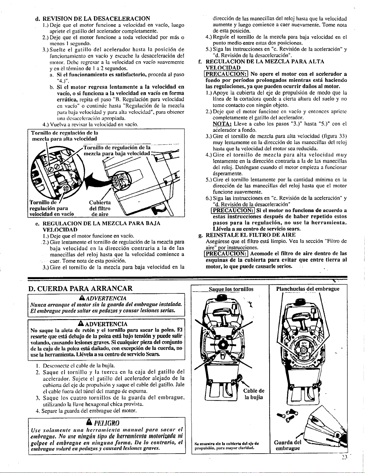
d. REVISION DE LA DESACELERACION
1.) Deje que el motor funcione a vetocidad en vacfo, luego
apriete et gatillo del acelerador completamente.
2.) Deje que el motor funcione a toda velocidad por mils o
mctaos 1 scgundo.
3.)Suelte et gatillo det acelerador hasta la posici6n de
funcionamiento en vac_o y escuche la desaceleraci6n de[
motor. Dcbc rcgresar a la velocidad cn vacfo suavemente
ycn el t6rmino de I a 2 segundos.
a. S| el funcionamiento es satisfactorio, proceda al paso
"4.)".
b. Si el motor regresa lentamente a la velocidad en
ratio, o si funciona a la velocidad en vacio en forma
err'.itica, repita el paso "B. Regulaci6n para velocidad
cn vacfo '° o contintie hasta "Regulaci6n de la mezcla
pa,'a baja vclocidad y para alta velocidad", para obtcncr
una dcsacclcraci6n apropiada.
4.) Vuelva a revisar la velocidad en vacfo.
Tornillo de regulaei6n de la
mezcla para alta velocidad
de regulaci6n de la
\
Tornillo de
regulaei6n para
veloeidad en vacfo
Cubierta
det filtro
de aire
e, REGULACION DE LA MEZCLA PARA BAJA
VEI,OCIDAD
direcci6n de las manecillas del reloj hasta que la vetocidad
aumente y luego eomience a caer nuevamente. Tome nora
de esta posici6n.
4.) Regule el tornitlo de ta mezcla para baja velocidad en el
punto medio entre estas dos posiciones.
5.) Siga las instrucciones en "c. Revisi6n de la aceleraci6n" y
"d. Revisi6n de la desaceleraci6n".
REGULACION DE LA MEZCLA PARA ALTA
VELOCIDAD
[PRECAUCION:! No opere el motor con el aeelerador a
rondo por perfodos proiongados mientras est_i haciendo
las regulaciones, ya que pueden ocurrir dafios al motor.
1.) Apoye la cubierta de[ eje de propulsi6n de modo que la
linea de la cortadora quede a cietta altura del suelo y no
tome contacto con ningfin objeto.
2.) Dcje que cl motor funcione en vacfo y cntonces apriete
completamente el gatil!o de! acelerador.
NOTA: Lleve a cabo los pasos "3,)" hasta "5.)" con el
a_elerador a fondo.
3.) Gire el tornillo de mezcla para atta velocidad (figura 33)
muy lentamente en la direcci6n de las manecillas de! reloj
basra que la velocidad del motor sea reducida.
4.)Gire el tornillo de mezcla para alta velocidad muy
Ientamente en la direcci6n contraria a la de las manecillas
del reloj. Det6ngase cuando el motor empieza a funcionar
_isperamente.
5.) Gire el tornillo lentamente pot la cantidad mfnima en ta
direcci6n de las manecillas del reloj basra que el motor
funcione suavemente.
6.) Siga las instrucciones en "c. Revisi6n de la aceleraci6n" y
"d. Revisi6n de la desaceleraci6n"
{PRECAUCION:] Sl el motor no funciona de aeuerdo a
estas instrucciones despu_s de haber repetido estos
pasos para la regulaei6n, no use la herramienta.
Ll_vela a su eentro de servieio sears.
I.) Deje que el motor funcione en vacfo.
_2.) Gire lentamente el tornillo de regulaci6n de la mezcla para
baja velocidad en Ia direcci6n contraria a la de las
manecillas del reloj hasta que la velocidad comience a
:, caer. Tome nora de esta posici6n.
3.)Gire el tornillo de la mezcla para baja velocidad en la
I I1 I I IIIIIIII1111111111
D. CUERDA PARA ARRANCAR
I_ ADVERTENCIA
Nunca arranque el motor sin la guarda del embrague instalada.
E! embrague puede sattar en pedazos y causar lesiones serias.
/_ ADVERTENCIA
N(_saque la aleta de ret_n y el tornlUo para saear la polea. E!
resorte que estfi dehajo de la polea estfibajo tensi6n y puede salir
volando, cau._mdo lesiones graves. Si cualquier pieza del conjunto
de la caja de la polea est..idafiado, con excepci6n de la cuerda, no
use la herramienta. Ll_vela a su eentro de servicio Sears.
I. Desconccte el cable de la bujfa.
2. Saque el tornillo y la tuerca en la caja del gatillo deI
acelerador. Sujete el gatillo del acelerador alejado de la
ct,bicrta del eje de propuisi6n y saque e! cable del gatillo. Jale
el cable fuera del ttinel dcl mango de espuma.
3. Saque los cuatro tornillos de la guarda del embrague,
utilizando la llave hexagonal chica provista.
4. Sepm'e la guarda del embrague del motor.
A PELIGI#O
] Use solatnettte tttta herramienta manual para saear el
I¢mbrag.e, No use niugrbt tipo de herramicnta motorizada ,i
I golpee el embrague en ninguna fornla. I)e Io eontrario, et
] embrltgtt¢ volard en pe_htzos y causard l_slones graves,
Ill I
g. REINSTALE EL FILTRO DE AIRE
Asegtirese que el filtro est_i limpio. Vea la secci6n "Fittm de
aire" por instrucciones.
IPRECAUCION:I Acomode et filtro de aire dentro de las
esquinas de la eubierta para evitar que entre tierra al
motor, 1oque puede causarle serios. :
I I ]llllllllll I I
%
Saque los tornillos Planchuelas del embrague
Cable de
la bujia
Guarda del
embrague
•'_uiiitt_mlrli .In I. _uhterl,, dd oJ_ de
proputsith_, imra may(_r durldad,
23
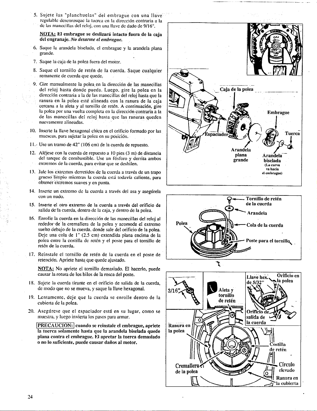
• :)
.
6_
7.
Sujete las "planchuelas" det embrague Con una tlave ......
rcgulablc dcscnrosquc ta tucrca cn la dircccidn contraria a la
de tas manccillas dcl rcloj, con una Ilave de dado de 9/16".
!
El embrague se deslizar:i intacto fuera :de ia caja
del engranaje. No desarme el embrague.
Saque la arandela biselada, el embrague y la arandeta plana
grande.
Saque ta caja de la polea fuera del motor.
8. Saque el tornitlo de ret_n de la cuerda. Saque cualquier
remanente de cuerda que quede,
9. Gire manualmente la polea en la direcci6n de las manecillas
del rel0j hasta donde pueda, Luego, gire la polea en la
direcci6n contraria a ta de las manecillas del reloj hasta que ia
ranura en la polea est6 atineada con ta ranura de la caja
cercana a la aleta y al tornil!o de ret6n. A continuaci6n, gire
la polea pot una vuelta completa en la direcci6n contraria a la
de las manecillas del reloj hasta que las ranUras queden
nuevamente alineadas.
10.
11.,
12.
13.
14.
15,
16.
17.
18.
19.
20.
lnserte la !lave hexagonal chica en el orificio formado pot las
muescas, para sujetar la polea en su p0sieidn.
Use un tramo de 42" (t06 cm) de la cuerda de repuesto.
Aldjese con la cuerda de repuesto a 10 pies (3 m) de distaneia
del tanque de combustible. Use un f6sforo y derrita ambos
extremos de la cuerda, para evitar que se deshilen.
Jale los extrcmos dcrretidos de la cuerda a trav_s de un trapo
grt, eso'li/lipio mient,'as la cuerda estti todavfa caliente, para
obtener ekt?emos suaves yen punta.
Inserte un extrcmo de la cuerda a trav6s del asa y asegtirela
COil LIII nLIdo.
[nserte el otro extremo de la cuerda a trav6s del orifleio de
salida deta cuerda, dentro de la caja, y dentro de la polea.
Enrolte ta cuerda en la direccidn de Ias manecillas del reloj al
rededor,de:ta cremallera de Ia polea y acomode el extremo
suelto debajo de la cuerda, donde sale del orificio de la polea.
Deje una cola de 1" (2.5 cm) extendida ptana encima de la
polea entre la costilta de retdn y el poste para el tornitlo de
retdn de la cuerda.
Reinstale el torniI!o de ret_n de la cuerda en el poste de
retenci6n. Apriete hasta que quede ajustado.
No apriete el tornillo demasiado. El haeerlo, puede
causar la rotura de los hilos de la rosca del poste.
Sujete la cuerda tirante en el orificio de salida de la cuerda,
de modo que no se mueva, y saque la llave hexagonal.
Lentamente, deje que la cuerda se enrolle dentro de la
cublerta de la polea.
Asegfirese que el espaeiador est,5 en st, lugar, como se
muestra, y luego invierta los pasos para armar.
IPRECAUCION: ]cuando se reinstale el embrague, apriete
la tuerca solamente hasta que la arandela biselada quede
plana contra el embrague. El apretar la tuerca demasiado
o no lo sufieiente, puede causar dafios al motor.
Embrague
Tuerca
Arandeta
plana
grande
Arandela--
biselada
(La curva
va hacia
el cmbrague)
Polea
-4---. ornillo de ret_n
de la cuerda
Arandela
Cola de la cuerda
Poste para el tornillo_
Aleta y
tornillo
de retch
[Llave hex? Orificio en
de 5/32" _la polea
kanura en
la polea
Costilla
de retch
Cremallera
de la polea
Cfrcul_
elewldo
Ranura en
cubierta
24
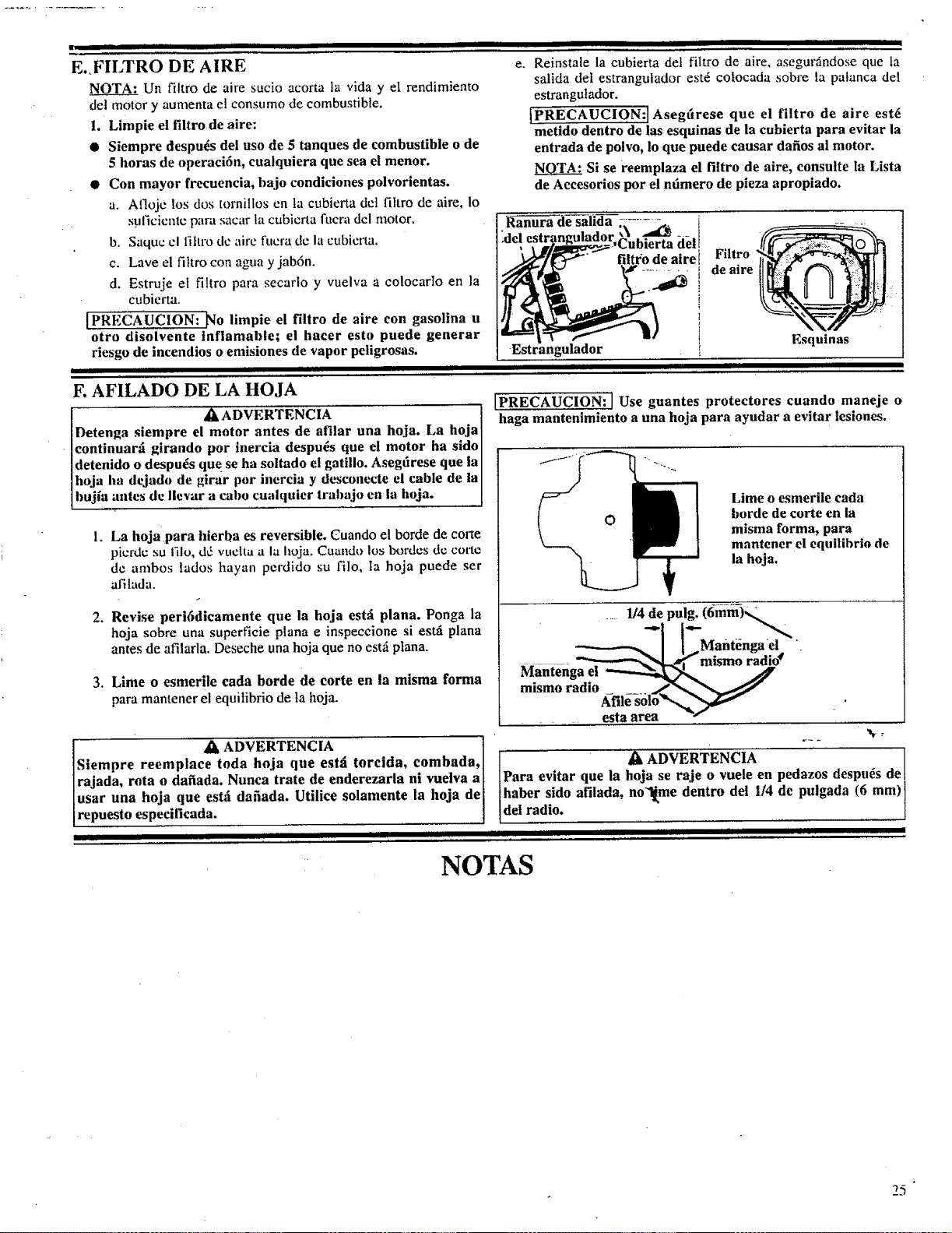
E.,FILTRO DE AIRE
_4OTA: Un filtro de aire sucio acorta la vida y el rendimiento
del motor y aumenta el consumo de combustible.
L Limpie el filtro de aire:
• Siempre despu_s del uso de 5 tanques de combustible o de
5 horas de operaci6n, cualquiera que sea el menor.
• Con mayor frecuencia, bajo condiciones polvorientas.
a. A1]ojc los dos tornillos en ta cubierta dcl filtro de aire, Io
suficicnlc para sacar ta cubicrta fuera del motor.
b. Saquc cl fihro de airc fucra de la cubierta.
c. Lave el filtro con agua y jab6n.
d. Estruje et filtro para secarlo y vuelva a colocarlo en la
cubierta.
[PRECAUCION: _o limpie el filtro de aire con gasolina u
otro disolvente tnflamable; el haeer esto puede generar
riesgo de incendios o emisiones de vapor peligrosas.
I i i i i II iiii iiiiM i i i lilillill
e. Reinstale la cubierta del fittro de aire, asegurfindose que ta
salida del estrangulador est6 cotocada sobre la palanca del
estrangutador.
[PRECAUCION:] Asegtirese que el filtro de aire est_
metido dentro de las esquinas de la cubierta para evitar la
entrada de polvo, 1o que puede causar dafios al motor.
NOTA: Si se reemplaza el filtro de aire, consulte la Lista
de Accesorios por el ndmero de pieza apropiado.
filtro de aire! Filtro
........ i de aire
1
1
1
Estrangulador I
II II II I I IllllllII Illlllllllllll
F. AFILADO DE LA HOJA
l LI, ADVERTENCIA
Detenl_a s!empre el motor antes de afilar una hoja. La hoja 1
continuara girando por inereia despu_s que el motor ha sidol
detenido o despu_s que se ha soltado et gatillo. Asegdrese que lal
hoja ha dejado de girar por inercia y desconecte el cable de la]
bujia attics de llevar a cabo cualquier tralmjo cn la hoja. [
Esquinas
[PRECAUCION:] Use guantes protectores euando maneje o
haga mantenimiento a una hoja para ayudar a evitar lesiones.
.
La hojapara hierba es reversible. Cuando el borde de corte
picrd¢ su filo, d_3vuclta a la hoja. Cuando los bordes dc torte
de ambos lados hayan perdido su filo, ta hoja puede ser
afilada.
Lime o esmerile cada
borde de corte en la
misma forma, para
mantener el equillbrio de
la hoja.
.
,
Revise peri6dieamente que ia hoja est_ plana. Ponga la
hoja sobre una superficie plana e inspeccione si estfi plana
antes de afilarla. Deseche una hoja que no estfi plana.
Lime o esmerile cada borde de corte en la misma forma
para mantener el equitibrio de ta hoja.
. 1/4 del pul_.(6mm) _
_____.i!
Manteug_mism° r_, °€
mismo radio ..... __,I_,,__
• eKsfilta6a_"__
l " ,_ ADVERTENCIA ] "-"
]Siempre reemplace loda hoja que est:i torcida, combada,l ] Ax ADVERTENCIA pedazos despu_s de[
/rajada, rota o dafiada. Nunca trate de enderezarla ni vuelva a[ [Para evitar que la hoja se raje o vuele en de pulgada (6 mm)]
[usar una hoja que estfi dafiada. Utilice solamente la hoja de[ [haber sido afilada, no'l[.me dentro del 1/4
[repuesto especificada. ] ldel radio.
• I I I I Illll [I I I I [ II [ II I[ll I Illl I II II
NOTAS
25
+m_.. :e : iii_ L Ull iii II "llllllllllillll lllSmUlllllllllllllllllllllllillillllllllllj IIHIII iiii i iii
ALMACENAMIENTO
ii iiiiiiHimi i i
Si su unidad no va a usarse durante 30 dfas o m_is prep_irela
inmediatamente para almacenar al final de la temporada.
ADVERTENCIA:
PERMITA QUE EL MOTOR SE ENFRIE Y
ASEGURE LA UNIDAD ANTES DE
ALMACENARLA O TRANSPORTARLA EN
UN VEHICULO.
ALMACENE LA UNIDAD +Y EL
COMBUSTIBLE EN UN AREA DONDE LOS
VAPORES DEL COMBUSTIBLE NO PUEDEN
LLEGAR A LAS CHISPAS O LLAMAS
ABIERTAS DE LOS CALENTADORES DE
:AGUA, MOTORES ELECTRICOS O
INTERRUPTORES, HORNOS, ETC. +
ALMACENE LA UNIDAD CON TODAS LAS
GUARDAS EN SU LUGAR. COLOQUE EN
POSICION DE TAL MANERA QUE LAS
CUCHILLAS NO PUEDAN CAUSAR
LESIONES ACCIDENTALES LA LOS
TRANSEUNTES.
ALMACENE LA UNIDAD FUERA DEL
ALCANCE DE LOS NliqOS.
INSTRUCCIONES PARA EL ALMACENAMIENTO DE
LA CORTADORA/CORTADORA DE MATORRALES
Limpie completamente su cortadoraicortadora de matorrales antes
de almacenarla siva a ser almacenada durante un perfodo de
tiempo. Elimine toda ta tierra, aserrin, hojas, aceite, grasa, etc.
Almacene enun firea limpia y seca.
* Limpie to++ala unidad.
* Limpie el fihro de aire. Refi_rase a "Responsabilidades del
cliente".
, Abra el conjunto del cabezal de corte y limpie la tierra, c+sped o
desechos acumulados. Inspeccione la lfnea de corte y si es vieja
(apariencia de tiza y pegajosa al tacto) saquela y des6ehela+
Instale una nueva Ifnea la pr6xima vez que se va ausar el
producto.
o Aceite ligeramente las superficies externas de metal para evitar
que se forme 6xido.
PRECAUCION: Use guantes protectores al
mane jar la cuchilla. La cuchilla est:i afilada y
puede cortarlo afin cuando est_ inm6vil.
Si su unidad estzi equipada con una cuchilta, s_quela de ia
unidad+ Refi+rasc a "Armado". Aplique un recubrimiento de
aceite a toda la superficie de la cuchilla y envu+lvala en papel
grueso, trapo o pl_Jstico. Aplique tambi<_nuna capa delgada de
aceite al enroscado de la caja de engranajes y acontinuaci6n
ajuste bien la tuerca de la cuchilla para el almacenamiento.
Vuelva a armar todas las piezas suehas, asegur.,hldose qua todos
los mangos y guardas est6.n en su lugar y firmemente sujetos.
Reemplace las piezas dafiadas.
iiiii iJlll iiii ..........
MOTOR
Nunca use productos limpiadores para motor o carburador en el
tanque de combustible ya que pueden causar dafios permanentes.
Siga estas instrucciones:
a. Drene el combustible de ta unidad dentro de un recipiente
aprobado de combustible.
b. Vacfe las tuberfas de combustible y el carburador arrancando
el motor y permiti_ndolo funcionar hasta ctue se detenga.
c+ Permita que el motor se enfrfe antes de almacenar.
IMPORTANTE: Es importante evitar que se formen dep6sitos de
goma en las piezas esenciales det sistema de combustible tales
como el car+burador, filtro de combustible o el tanque durante el
almacenamiento. La experiencia indica tambi6n que los
combustibles mezclados con alcohol, aquellos que usan etanol o
metanol (ltamados gasohol o combustible 0xigenado) pueden atraer
ta humedad y formar gas acfdico, que dafiar_, su motor. El sistema
de combustible deberfa vaciarse antes de almacenar por 30 dfas o
re+ispara evita r problemas con el motor.
NOTA" El estabilizador de combustible es una alternativa aceptable
para minimizar la formaci6n de dep6sitos de goma del combustible
durante el almacenamiento+ Agregue el estabilizador a la gasolina
en un tanqu e o reeipiente de almacenamiento. Siga siempre tas
instrucciones de mezcla de combustible indicadas en el recipiente
del estabilizador. Haga funcionar el motor durante por Io menos
diez+minutos despu_s de agregar el estabilizador para permitir que
6ste llegue el carburador.
.N__Q.T._: El aceite de motor de 2 tiempos CRAFTSMAN 40:1 estzi
especialmente combinado con estabilizadores de combustible.
Usted puede agregar un estabilizador de combustible (tal como el
Craftsman No. 33500) a su tanque de combustible si no usa este
aceite Sears.
• Saque la bujfa y vierta una cucharita de t+ de mezcla de aceite
40:1 a trav6s de la abertura de la bujfa. Tire lentaniente de 8 a 10
veees de la cuerda para arrancar para distribuir el aceite+ .las
superficies interiores del motor.
+ Reemplaee la bujfa por una nueva del tipo y alcance t6rmi¢o
recomendados. Refi6r_e a "Especifieaciones del Producto +'.
+ • • • • _ i* • •
• + L+mpte el filtro de ai_. Refierase a Responsabthdades del
Cliente".
+ Vuelva a instalar todas las cubiertas y la ferreterfa sacada para
obtener acceso; ajuste todos los tornillos y sujetadores+
• Revise toda la unidad por tornillos, tuercas y pernos flojos.
Reemplace las piezas dafiadas, rotas, o desgastadas.
• AI comienzo de la temporada pr6xima use combustible fresco
que tenga la proporci6n adecuada de gasolina a aceitc.
OTRAS
° No almacene la gasolina de una temporada a otra.
° Reemplace su lata de gasolina si comienza a oxidarse. El 6xido
ylo la suciedad en su sistema de combustible causar_i problemas.
° Almacene su unidad en un firea bien ventilada y cubierta, si fuera
posible, para evitar la acumulaci6n de polvo y fie_rra. No cubra
con pl+istico. El pl_istico no puede respirar e inducirzi
condensaci6n y eventual mente oxidaci6n o corrosi6n+
IMPORTANTE: Ntmca cubra la unidad mientras las _ireas del
motor y dd cseul_eest+ntodavfac+lientcs.
26
II I Illllll Illlllllll
INDICE
i i iii IIIImmII_lIIJlllI
A|_ERTURA DE LA ]_UJ|A .......................................................... 2
ABERTURA I)EL MODUI,O " "
DE AIRE ...................................... 2
ACCESORIOS ................................... . ............................. _....... .....20
ACEITE, MOTOR
Proporci6n con gasolina .......................................................... l I
Tipos para usar; para no usar..,.. ....... _..................... .. ...... :...... ,1 t
ACEITE PARA El, MOTOR
Proporci6n con gasohna ............................... ........................... I I
Tipos a usar; para no usar ....... 7 ............................................... ! I
ADVERTENCIAS E INSTRUCCIONES DE SEGURIDAD.....4
ADVERTENCIAS E INSTRUCCIONES
PARA LA SEGURIDAD ......... i..... _................... ..................... 4
ALMACENAtVlIENTO ................................................................ 25
ARMADO
' Cabeza de la cortadora ............................... :.............................. 6
Cable del acelerador ......................................... ............ ;............ 7
Correa para el hombro ............................................................. I 0
Escudo
• x,
Cortadora de hnca .............................................................. 8
Hoja para hicrba ................................................................. 9
Grapa, correa para el hombro .................................................. 10
Ho a ............... _........................... :_........ ................ . ........ . ............ 9
Hoja para hierba ................................. .,.,._............. ................. ...9
Manubrio .......................................................... ........................ ,7
Pt cpm ac ton ................................................................................ 6 -
ARMADO DE LA GRAPA PARA LA
CORREA PARA EL HOMBRO ............ ............. . ................ 10
ARRANCANDO UN MOTOR CALIENTE ............................. ,12
ARRANCANDO UN MOTOR CALIENTE DESPUES
DE IIAI_Eit AGOTAI)O TODO EL COM!IUS'rlBLE,.... 13
ARRANQUE CON EL MOTOR FRIO ...................................... 12
AVANCE AUTOMATICO DE LA LINEA ............................... 17
CABEZA DE LA CORTADORA
Armado ............................................... _...................................... 6
Desarmado ................... ...................................................... ;....... 6
Encaminando la hnea .............................................................. 19
F.?.,_cudo......................................................................... .: ......... _...8
Mantenimiento...: ................................................... ;................. 21
Segm tdad ................................................................................. 21
CARRETE
Instalaci6n ................................................ ............................... 20
Mantenimiento ......................................................................... 20
Pre-enrollados ............ ...................................... ........................ 20
Votviendo a enrollar ................................................................ 20
CARRETES PRE-ENROLLADOS ............................................ 19
COMBUSTIBLE
Almacenamiento ...................................................................... 11
Carga del combustible .............. ........................................... ;.,. t I
Mezcla de acclteigasohna ........................................................ 11
Mczclando el combustible ....................................................... I I
Seguridad ................................................... .... .......................... I 1
CON JUNTO DEL CABLE DEL ACELERADOR ..................... 7
CON JUNTO DE LA CAJA DE ENGRANAJES ......................... 6
CON JUNTO DE LA HOJA PARA HIERBA ..... .. ..................... 10
CONTENIDO DE LA CAJA ............... ........... . .............................. 5
CONTROLES .......................... . ...................................................... 2
CORREA PARA EL HOMBRO ................................................. 10
ESCUDO
Armado de la hoja ..................................................................... 9
Limitador de la linca .................................................................. 8
ESPECIFICACIONES ................................................................... 2
FILTRO DE AIRE .................................................................... _...25
GARANTIA .......................................................................... :.......... 2
(;ASOIANA
Proporci6n con aceite .............................................................. I 1
Tipos para usar, para no usar. .................................................. I 1
HO.IA, HIERBA
Afilath_...............................................................................i.....25
l_lan'era ¢ontra €1 r_:bntc dr: ht hoja ........................................... If!
Manlcnimieqto ......................................................................... 25
M&odos de torte ..................................................................... 16
Scguridad ................................................................................. 15
INSTRUCCIONES PARA ARRANCAR ................................... 12
IImlllllllllllIII IIIIII Illll t Illl lull
LINEA
' Avarice .......... ;.......................................................................... 17
Diagn6stico de problemas .................................. :..._................ 26
Encaminando en la cabeza ...................................................... 19
Enrollando en e! carrete ............... ............................................ 20
Largo
Operaei6n ......................................... . ........................... i... 17
' A cortar como repuesto ............. .......................... _....... ..... 18
Repuesto ............................ ;..._.:........ :...................................... 19
Rotura ...................................................................................... 26
Seguridad .................. , ............................................................. 20
Tamafio a usar ......................................................................... 26
LISTA DE PIEZAS DE REPUESTO ......................................... 27
LISTA DE PIEZAS PARA REPARACIONES ......................... 28
LUBRICACION
: Eje de propulsi6nflexible ........... _............................................ 2 I
Motor ....................................................................................... 1 I
LUBRICACION DEL EJE DE PROPULSION FLEXIBLE...2 I
MANTENIMIENTO
Cabeza de la cortadora ............................................................ 16
Carburador ................................... ,,; .............. .......................... 22
Cuerda para arrancar. .............................................................. !2
Eje de propulsi6n flexible ........................................................ 21
Filtro de aim ............................................................................ 25
Hoja, hierba ............................................................................. 25
Seguridad ...... ........................................................................... 2 I:i
Tabta de diagn6stico de problemas ......................................... 26
METODOS PARA CORTAR
Cortadora de lfnea ................................................................ 18
Hoja para hierba ............................... ... ........................... _........ 25
MOTOR
Almacenamiento ...................................................................... 1I
Carburador ............................................................................... 22
Controles ...... ;. ............... ;.................. _................................ _....... 2
Cuerda para arrancar. ..... _.............................................. . ......... 12
Diagn6stico de problemas .... ................................................... 26
Filtro de aire ........ ;................................................................... 25
Instrucciones para arranear ........................... :.......................... 12
Mezcla de combustible ....... . .................................................... I t
OPERACION
Arrancando el motor ................................................................ 12
Avance de ta Ifnea ................................................................... 17
Barrlendo ............................................................................. _8
Cortando al ras ................... :...................................................... 8
Cortando el c_sped .............. .................................................... ! 8
ttoja para hierba ...................................................................... 20
Parando et motor ........ _. ....................................................... 13
Podando ...... ............................................................................. 18
Posici6n .................... ............................................................... 12
Revisiones pre-operatorias ...................................................... 12
Seguridad
Hoja ............................................................................ 16, 17
Limitador de Ifnea ............................................................ 17
Velocidad ................................................................................. [ 5
PAGINA DE REFERENCIAS RAPIDAS .................................. 31 _"
PARACHISPAS ............ _....................... . ............................. ........... .'5
REEMPLAZO DE LA CUERDA PARA ARRANCAR ........... 24
REGULACIONES
Abertura del m6dulo de aire ...................................................... 2
Abertura de ""
la bujm ....................................................................
Avarice de la Ifnea ................................................................... 17
Cable del acelerador ..................... ............................................. 7
"39
Carburador ............................................ _............................ ".......
Correa para el h0mbro ............................................................. 10
Manubrio ................................................................................... 7
REGULACION DEL CARBURADOR ........................................
REGULAC!ON PARA VELOCIDAD EN VAC!O ............. 22
TAI!t,A DE DIAGNOSTIUO DE AVLRIAS .............................. 6
USANDO SU HERRAMIENTA COMO
CORTADORA PARA HIERBAS ........................................ 16
USANI)O SU HERRAMIENTA
COMO CORTADORA DE LINEA ..................................... 17
27

TABLA DE DIAGNOSTICO DE PROBLEMAS
SINTOMA CAUSA I SOLUCION
El motor iioalTanea o s(_lO fun_iolla I.
pot unos .,,cgundos despuds dc
arrancar. 2.
E1 motor no funch:_ua en fornla
apropiada a velockktd cn vacfo.
El motor no acelera, [e fafta potencia
o se apaga cuando se comienza a
_ollar,
Tanque de combustible ratio.
El motor est_iahogado.
3. La buj[a no dispara.
4, No Ilega combustible al carburador.
5. El carburador necesita regulaci6n.
6. Ninguno de lo anterior.
I, El carburador necesita regulaci6n.
2, Ninguno de Io anterior,
I. El fihro de aire est,5 sucio.
2. La buj[a esui sueia.
I. Llene el lanquc con la mczcla de combustible
co,Tecta.
2. Vea las "Instrucciones para arrancar."
3. Instale una nueva bujia; revise c[ sistema de
enccndido.
4. Limpie el filtro; revise la tfnea de combustible.
5. Vea "Regulaei6n del earburador,"
6. •Consulte con su centro o departamento de
• servicio de Scars,
............... IT-Ve_a "Regulaci6n del carburador."
2. Consulte con su centro o departamento de
servicio de Sears.
3. El carburador necesita regulaei6n.
4. Las salidas del silenciador est_n obstruidas.
:5.
E1 motor hecha humo excesivo. 1.
2.
3,
Ninguno de lo anterior.
El filtro de aire est,, sucio.
La mezcla de combustible es incorrecta.
E1 carburador necesita regulaci6n.
I. La mezcla del combustible en incon'ecta.
2. Et carburador necesita regulaei6n.
3. La bujia es incorrecta,
4. Ninguno de 1o anterior.
El motor se calicma.
La cabeza de ta cortadora se detiene i.
al cortar, o no gira cuando se 2.
acelera el motor.
La [rhea no avanza o se rompe al
t2(ll'lal'.
La lfnea se pcga al carrcle.
La [inca sc sucha continuamente.
El uso de la [inca es excesivo.
E! eje de propulsi6n est,'i roto.
El cje de propulsi6n esfft desconectado.
I. La lfnea est,5 real encaminada en la cabeza.
2, La tfnea estfi mal enrollada en el carrete,
3. E1 tamafio de la h'nea es incorrecto.
4. Muy poca lfnea fuera de Incabeza.
5. Hay tierra acumulada en los recortes de la cubierta.
I. El tamafio de Ia ffnea es incorrecto.
2, Se est_i forzando la tfnea contra el material quesc
cotla.
3. Se estfi cortando a mayor velocidad que la necesaria.
1. El bot6n de avarice est;i atascado.
2. El bot6n de avanec se hit dcsprendldo det cubo.
I. El tamafio de la linea es incorrecto,
2, Se estll cortando a alia velocidad alrededor de objetos
duros.
3. Se est_i flwzando la lfaea contra el material que se
corta.
Mtty poca ffnea fuera de la cabeza.La linea se retrae denim de [a cabcza. *
I. Limpie o reemplace el fihro de aim.
2. Limpie o reemplace la bujfa y regule la
abertura.
3. Vea "Regulaci6n del carburador."
4. Consulte con su centro o departamento de
servicio de Sears.
5. Consulte con su centro o departamento de
servicio de Sears.
t. Limpie o reemplace el fihro de aire.
2, Vea "Cargando combustible a su unidad."
3. Vea "Regulaci6n del carburador."
1. Vea "Cargando combustible a su unidad.
2. Vea "Regulaci6n del carburador."
3. Reemplace con ta buj fa correcta.
4. Consulte con su centro o departamento de
servieio de Sears.
1. Reemplace el eje de propulsi6n.
2. Vea "Armado,"
I. Saque la cubierta. Revise el eneaminado de la
lfnea.
2. Vuelva a enrollar en forma uniforme y
apretada.
3. Use solamcnte la Lfnea Laser de Sca_ de .080"
(2 ram),
4. Saque la eubierta. Jale 4" ( 10 cml de linea'h'trera
de la eabeza.
5. Limpie los recortes de la cubicna.
l._:Use solamente la Lfnea Laser de Sears de .080"
(2 mm).
2. Cone con la punta de la [fnea.
3. Reduzca la ve!ocidad para el torte.
1. Saque y limpie el bot6n de avancc.
2. Yea "Instalando el carrete con lfnca.
1. Use sotamente la Lfnea Laser de Scars de .-tlS()"
(2 mm).
2. Reduzca la velocidad alrcdedor dc los objetos
duros.
3. Corte con la punta de la Ifnea:
• Saque la cubiena. Jale 4" ( 10cm} de Ifllea fuera
de Incabeza.
28

L i HIIlll
I I II lllll
Ill [ I I[ H[ll[[[[[llllIHl[[[lIH I II [llllllllllllll[l[I
NOTAS • _::"' ::_
29

IIIIIII III II II III II II IIJJl I
NOTAS
III
3O
PAGINA DE REFERENCIAS RAPIDAS
Lea y siga todas las advertencias e instrucciones para seguridad y las instruccimles
para la operaci6n. Ix, omisi6n de esto puede resultar en lesiones graves.
Pfigina No.
PREPARACION .................. ..................................................................................................................... 3
I. Aprenda todas tas advertencias e instrucciones de seguridad contenidas en este manual.
2. Use una m_iscara de seguridad para Ia cara o anteojos de scguridad.
3. Vfstase de mantra segura: botas o zapatos de seguridad, pantalones largos.
4. Revise pot piezas gas,arias, st,ellas, fahantes, o dafiadas; reemptace esas piezas como sea neeesario antes de usar la herramienta.
5. [nspeccione y compruebe quc el z_rea a eortar es segura.
6. Mantenga a los nifios, observadores y animales alejados a 30 pies (10 m) de distancia.
CARGA DE COMBUSTIBLE .............................................................................................................. 11
t. Elimine toda fnente de chispas o llamas en el sitio donde mezcla, guarda o carga el combustible.
2. Use 40 partes de gasolina regular sin plomo para 1 parte de aceite para motor de 2 tiempos enfdado por aire.
3. Use combustible limpio y fi'esco.
4. Mezcle y almacene el combustible en un recipiente aprobado y marcado
5. Mezcle y vierta el combustible en un _rea exterior.
6. AI6jcse un mfnimo de 10 pies (3 m) del combustible y deI sitio donde carg6 el combustible antes de arranear e! motor.
ARRANCANDO EL MOTOR .............................................................................................................. 12
!. Extlenda 6 pulgadas (15 cm) de Ifnea fuera de la cabeza. ',,
2. Apoye cl cscudo en el sueto sujetando la cabeza de la cortadora fuera del suelo y alejada de objetos y de observadores.
3. Mantenga el gatillo del acelerador apretado completamente hasta que el motor funcione.
4. Jale la cuerda para arrancar firme y r_ipidamente.
OPERANDO LA HERRAMIENTA .................................. ................................................................... 14
I. No opere la herramienta a velocidad mayor que ta necesaria.
2. Suelte el gatillo del acelerador cuando no est_ cortando. "- -
3. Apague el motor moviendo el interruptor de encendido a la posici6n "Apagar".
MANTENIMIENTO .......................................................... ;................................................................... 21
I. Agote el combttstible de la t, nidad antes de guardarla.
2. Desconccte la bujfa antes de Ilevar a cabo cualquier mantenimiento, excepto para ta regulaci6n det carburador.
3. Limpie el filtro de aire I'recuentemente, pero siempre despuds de consumir 5 tanques de combustible.
4. Guarde su unidad en un lugar seco y fuera del alcance de los nifios.
..................... Y"
31
[
Manual del
operario
r
MODELO NO.
358.797260-32cc
C6mo pedir piezas
de repuesto
EL SERVICIO SEARS
EST A SU SERVICIO +
Et ntimero demode[o se encuentra debajo del mango superior junto con el ntimero de serie.
Siempre mencione el ntimero del modeZo cuando solicite un servicio o piezas de repuesto
para su sierra de cadena.
Todas las piezas aquf listadas pueden ser pedidas en cualquier centro de servicio SEARS y
en la mayor parte de las tiendas SEARS.
AL PEDIR LAS PIEZAS DE REPUESTO SIEMPRE INCLUYA LA SIGUIENTE
INFORMACION, COMO SE MUESTRA EN ESTA LISTA:
1. NUMERO DE PARTE 3.
2. EL NUMERO DEL MODELO 4.
358.797260
DESCRIPCION DE LA PIEZA
Et NOMBRE DEL ITEM.
Cortadora de hierba Weedwacker®
de 32cc
Si ias piezas que usted necesita no est_in disponibles localmente, su pedido serfi
trasmitido a un centro de distribud6n de piezas de repuesto de SEARS para set
alet_dido.
Cuando usted compra mercader_a de
SEARS, usted obtiene un valor extra que
nadie m_ ofrece: el servicio SEARS.
A tray,s de la ciudad o a trav6s del pals, el
servicio SEARS siempre est_i cerca, con su
plantel de t_cnicos de servicio competentes
y confiables, que usan solamente piezas
SEARS especificadas por la f_brica
Su mercaderfa SEARS adquiere un valor mayor cuando ustcd dcscubre que
tiene unidades de servicio SEARS a trav6s de todo el pals, Cada una tiene
un plantel profesional de t_cnicos entrenados por SEARS y que emptean
los m6todos aprobados pot SEARS.
Sears, Roebuck and Co., Hoffman Estates, IL. 60179 EE.UU.
IMPRESO EN EE.UU.