PRODUCT DATA
The Honeywell Trademark is used under license from Honeywell
International Inc. by Air-Pure Systems.
Honeywell International Inc. makes no representations or
warranties with respect to this product.
F57A,B
Flush-Mount Commercial
Electronic Air Cleaner
GENERAL
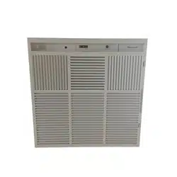
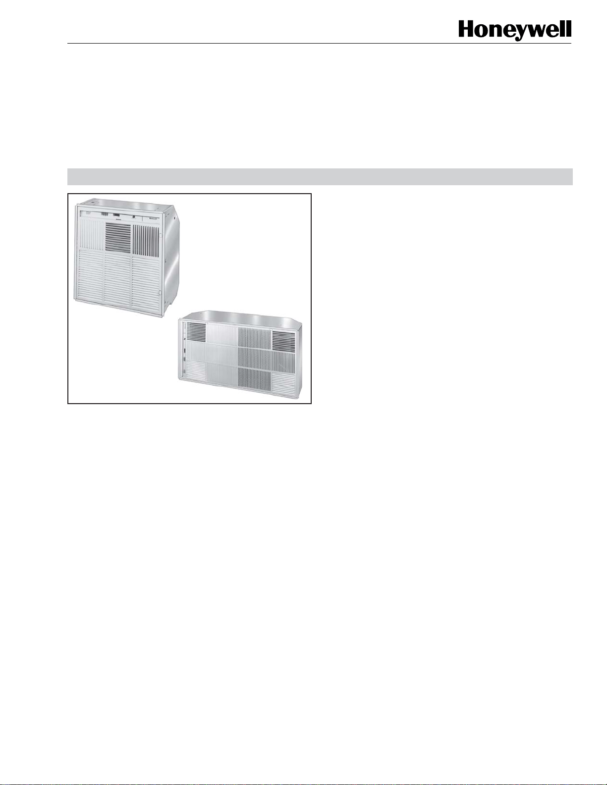
The F57A,B Flush-Mount Commercial Electronic Air Cleaners
are ceiling-mounted. The F57 removes airborne
contaminants such as tobacco smoke and dust from the air
circulated through the F57.
FEATURES
• Removes staining dirt from the air as measured by the
Dust Spot Method using atmospheric dust; refer to the
American Society of Heating, Refrigerating, and Air
Conditioning Engineers Standard 52.1-92.
• Three-speed motor-driven fan circulates up to 1030 cfm
(1750 m
3
/hr) on F57A, up to 485 cfm (714 m
3
/hr) on
F57B.
• Solid state power supply is self-regulating and maintains
peak efficiency during a wide range of cell dirt loading
conditions.
• Interlock switch prevents operation when the grille is
open.
• Heavy duty commercial cells and prefilter are removable
for cleaning.
• Air vent provides dilution control of gaseous
contaminants.
• Provides Coanda air distribution by drawing in dirty air,
cleaning it electronically, and recirculating the clean air in
six directions throughout the space.
• Light emitting diodes (LEDs) indicate ON and CHECK;
the WASH LED is optional.
• Test button shows the presence of high voltage.
• Available in 120 Vac, 60 Hz or 220–240 Vac, 50 Hz
models.
• Optional wall mounted remote switch.
• Optional hand-held infrared remote transmitter controls
up to nine F57s via infrared remote receivers. Some
models available with infrared receiver factory installed.
• Optional activated carbon filters controls ozone and
reduces occasional gaseous contamination.
•
READ AND SAVE THESE
INSTRUCTIONS
Contents
General............................................................................... 1
Features ............................................................................. 1
Specifications ..................................................................... 2
Ordering Information .......................................................... 2
Planning the Installation .................................................... 4
Installation .......................................................................... 7
Checkout ............................................................................ 10
Service ................................................................................ 11
Electrical Troubleshooting ................................................. 15
Parts List ............................................................................ 19
Limited One-Year Warranty ................................................ 24
68-0083-9 Revised 11-08
F57A,B FLUSH-MOUNT COMMERCIAL ELECTRONIC AIR CLEANER
68-0083-9 Revised 11-08
2
ORDERING INFORMATION
If you have additional questions, need further information, or would like to comment on our products or services, please
contact:
1. Your local Honeywell Commercial Air Products Distributor
2. Air-Pure Systems.
16873 Fish Point Rd. SE
Prior Lake, MN 55372-1714
Phone: (800) 998-1919
Fax: (800) 221-3248
www.cleanairfacility.com
.
SPECIFICATIONS
IMPORTANT
The specifications given in this publication do not
include normal manufacturing tolerances. Therefore,
this unit may not exactly match the listed
specifications. This product is tested and calibrated
under closely controlled conditions, and some minor
differences in performance can be expected if those
conditions are changed.
Models:
F57A Flush-Mount Commercial Electronic Air Cleaner:
contains two FC37B heavy duty commercial cells,
power supply assembly, prefilter, inlet-outlet grille,
power and speed control switch, performance selection
switch, collector test button, 3-speed motor driven fan,
interlock switch for the access grille, vinyl trim flanges,
exhaust air vent and LED indication of system
operation.
F57B Flush-Mount Commercial Electronic Air Cleaner:
same as F57A, except with only one FC37B heavy duty
commercial cell.
Color:
Off-white.
Solid State Power Supply Assembly:
203361A,B (F57A); 203361C,D (F57B).
Electrical Ratings:
Voltage and Frequency: 120 Vac, 60 Hz; 220–240 Vac, 50
Hz.
Current and Power Consumption:
Air Flow Capacity:
Efficiency:
Up to 95% efficiency using the Dust Spot Method measuring
atmospheric dust, according to the American Society of
Heating, Refrigeration, and Air Conditioning Engineers
(ASHRAE) Standard 52.1-92.
Motor:
F57A: 1/12 hp; sealed ball bearing.
F57B: 1/10 hp; sealed ball bearing.
Motor lubrication is not required.
Ambient Temperature Rating:
Shipping and Storage: minus 20×F to plus 150°F (minus
29°C to plus 66°C).
Operating: this equipment is intended for use at ambient
temperatures which are usually not higher than
77°F (25°C) but occasionally may be as high as 104°F
(40°C) for brief periods.
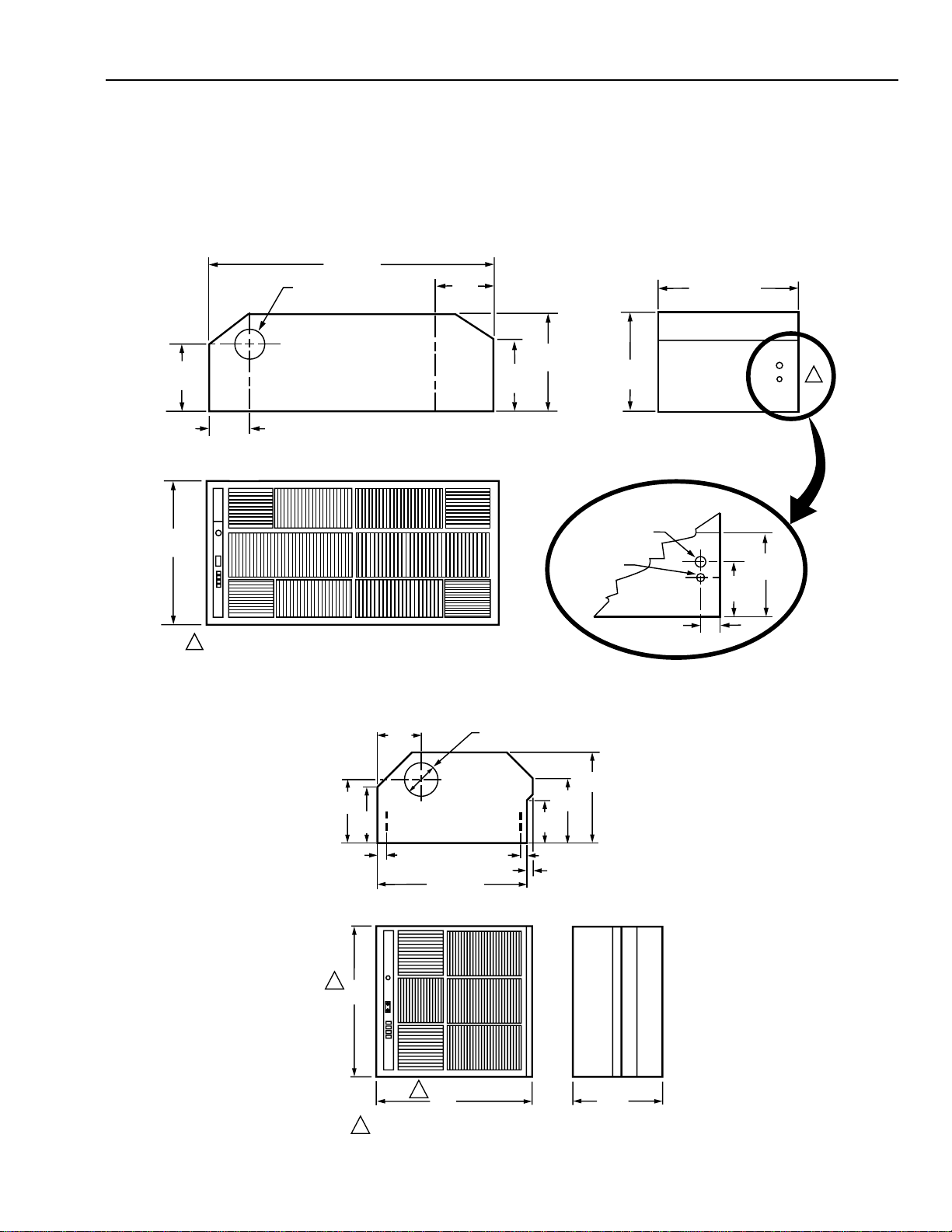
Dimensions:
See Figs. 1 and 2 for dimensions.
Shipping and Installation Weight:
A75FB75F
blgkblgk
ytuDyvaeH
lleClaicremmoC
)hcaE(
5.93.45.93.4
thgieWgnippihS
0.6011.840.460.92
thgieWdellatsnI
0.386.730.
455.42
naF
gnitteS
zH06,caV021
05,caV042/022
zH
AWAW
A75F
IH9.35138.1513
DEM2.30034.1052
WOL4.20022.1502
B75F
IH3.45529.1572
DEM1.25810.1051
WOL2
.1587.0001
naF
gnitteS
zH06,caV021zH05,caV042/022
mfcm
3
nim/mfcm
3
nim/
A75F
IH03019257852
DEM0960203712
WOL5556104681
B75F
IH5844106431
DEM082857311
WOL57150627
F57A,B FLUSH-MOUNTED COMMERCIAL ELECTRONIC AIR CLEANER
68-0083-9 Revised 11-08
3
5 (127) DIAMETER KNOCKOUT
46 (1168)
22
(559)
(343)
(569)
2
(51)
M5672C
FRONT VIEW
END VIEW
SIDE VIEW
TWO KNOCKOUTS FOR WIRING F57A.1
1
13-1/2
(343)
13-1/2
22-7/16
8-1/4
(210)
8-7/16
(213)
8-1/4
(210)
8-1/4
(210)
5-3/4
(146)
7/8 (22)
DIAMETER
1-1/8 (29)
DIAMETER
6-1/4
(159)
Approvals:
Underwriters Laboratories Inc. Listed: File no. E30954,
Guide no. AGGZ.
Canadian Standards Association Listed: File no.
LR19060.
The F57A,B Flush-Mounted Commercial Electronic Air
Cleaners meet all European Directives.
Replacement Parts and Accessories:
See Parts List on page 19.
Fig. 1. Approximate dimensions of F57A in in. (mm).
Fig. 2. Approximate dimensions of F57B in in. (mm).
5 (127) DIAMETER KNOCKOUT
SIDE VIEW
1
(25)
M5678D
FRONT VIEW
END VIEW
3/4 (19)
1 (25)
6-1/2
(165)
6-1/2
(165)
9-1/2
(242)
9-1/2
(242)
13-1/2
(343)
8-1/4
(210)
22-1/2(572)
22
(559)
22
(559)
13-1/2
(343)
1
1
GRILLE DIMENSION.
1
F57A,B FLUSH-MOUNT COMMERCIAL ELECTRONIC AIR CLEANER
68-0083-9 Revised 11-08
4
10
9
8
7
6
5
4
3
2
1
20
18
16
14
12
10
8
6
4
2
EXAMPLE 1
537
(50)
1075
(100)
1610
(150)
2150
(200)
2690
(250)
3230
(300)
3760
(350)
4300
(400)
AREA IN SQUARE FEET (SQUARE METERS)
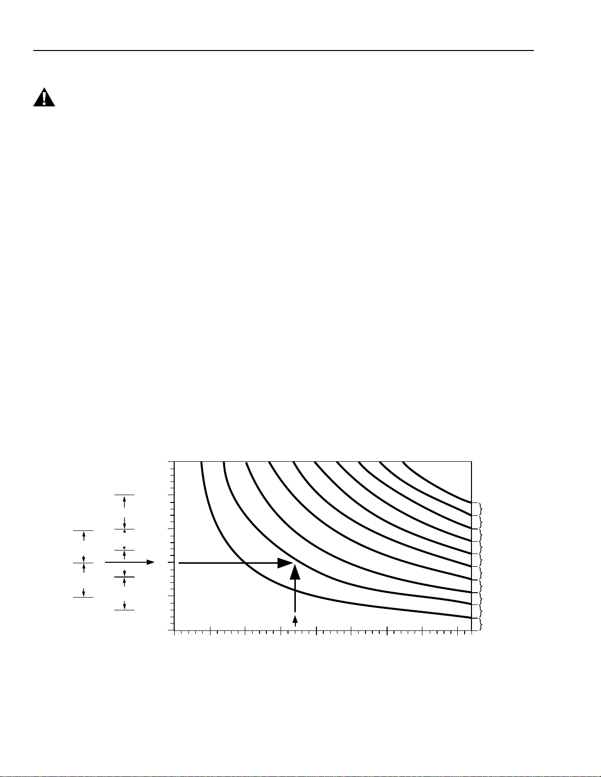
TO USE THE GRAPH:
EXTEND A HORIZONTAL LINE FROM THE DESIRED NUMBER OF AIR CHANGES PER HOUR, UNTIL IT INTERSECTS
WITH A VERTICAL LINE DRAWN UPWARD FROM THE NUMBER OF SQUARE FEET OF THE ROOM.
READ THE NUMBER OF UNITS REQUIRED AT THE INTERSECTION POINT.
1.
2.
25
20
15
10
5
0
BOWLING
CENTERS
PLACES OF
ASSEMBLY
STORES
OFFICES
RESTAURANTS
BARS
CAFETERIAS
LUNCHEONETTES
AIR
CHANGES
PER HOUR
F57A UNITS REQUIRED
F57B UNITS REQUIRED
M1206B
PLANNING THE INSTALLATION
WARNING
Explosion Hazard Possible
Can cause personal injury or equipment damage.
Do not install or use the F57 where there is any
danger of gas, vapor, or dust explosion.
Do not install when explosion-proof electrical fixtures
are specified.
Application and Operation
The F57 Flush-Mount Electronic Air Cleaner is designed for
use in restaurants, conference rooms, lounges, and offices
where overhead air cleaning is required.
Because the F57 provides its own air circulation, it can be
used in any situation that requires the removal of
contamination from an enclosed area.
Because it is not explosion-proof, the F57 must not be used if
there are dangerous levels of potentially explosive vapors,
gases, or dusts present in the cleaning area.
When the electronic air cleaner is powered, the fan draws the
contaminated air into the electronic air cleaner. Particles that
are too small to be caught in the prefilter are given an intense
electrical charge in the ionizer section of the electronic cell.
As the air passes through the collecting section of the cell,
the charged particles adhere to the collector plates, which
have a strong opposite charge. The cleaned air passes
through the fan component and re-enters the building
space.
Fig. 3. F57 sizing by air changes per hour and room area. In most cases, one F57B is equivalent to half an F57A because the
F57B airflow, although less than 50 percent of F57A airflow, is more effectively applied via several locations.
Two light-emitting diodes LED(s), ON and CHECK, are
included with the F57. The ON LED lights when the solid-
state power supply is powered and operating normally. The
CHECK LED lights if the F57 requires service attention or if
the test button is pressed. A WASH LED is also supplied
with the F57 but it is not factory installed. It can be field
installed using 4074 EMH Bag Assembly which is supplied
with the F57. See Fig. 4. The WASH LED lights to indicate
cell washing is overdue.
Determine Number of F57s Needed
The sizing procedure determines the number of F57As or Bs
needed. The correct number required for a particular
application depends on:
— type of contamination,
— number of occupants,
— volume of the room,
— use of the room,
— outdoor air quality.
This sizing information (Fig. 3) was generated using the
ASHRAE Handbook of Fundamentals, 1985; the ASHRAE
Standard 62-1989, Ventilation for Acceptable Indoor Air
Quality. It simplifies the sizing procedure for most
applications. Use this information as a guide; however,
remember that the F57 has different capacities for each fan
speed; see Specifications section.
The number of air changes per hour determines the amount of
air cleaning obtained. More air changes per hour than
recommended in the graph above are unnecessary because
the ASHRAE data used in the calculation is conservative.
Fewer air changes per hour than recommended in the graph
can be compensated for by bringing in more outdoor air to
maintain low contaminant levels, or tolerating a partially
cleaned atmosphere, which may be acceptable to some
users.

F57A,B FLUSH-MOUNTED COMMERCIAL ELECTRONIC AIR CLEANER
68-0083-9 Revised 11-08
5
15,000 ft
3
x 10 air changes per hour = 150,000 ft
3
/
hr
(432m
3
x 10 air changes per hour = 4320m
3
/hr).
Then determine the volume of air to be circulated
each minute.
150,000 ft
3
/hr
60 min/hr = 2500 ft
3
/min
4320 m
3
/hr
60 min/hr = 72m
3
/min
3. F57A capacity (HI setting) is 1030 ft
3
/min
(29m
3
/min).
Number of F57As required =
2500 ft
3
/min 72m
3
/min
1030 ft
3
/min 29m
3
/min = 2.4 or 3 units.
or
F57B capacity (HI setting) is 485 cfm (14m
3
/min).
Number of F57Bs required =
2500 ft
3
/min 72m
3
/min
485 ft
3
/min 14m
3
/min = 5 units.
Regardless of the method used for calculation, the physical
limitations of the space to be cleaned can influence the
number of electronic air cleaners required. For ambient air
cleaning, it is essential to establish a uniform airflow pattern
throughout the entire space. Fewer electronic air cleaners can
be installed because of a lack of mounting space. More units
may be required due to an oddly-shaped room that does not
lend itself to an even airflow.
If any questions should arise concerning size, consult your
distributor or local Honeywell Commercial Air Cleaner
Distributor.
Choose Location
The F57 is mounted horizontally, and can be used in almost
any air cleaning application that has a suspended ceiling. For
the most efficient operation, place the F57 as close as
possible to the contaminant source.
When placing the F57, be sure that the clean air discharge
enhances the airflow patterns of the area to be cleaned. For
example, do not place the air cleaner so its discharge disrupts
the flow from the central air handling system supply registers.
The shape of the room, location of central air conditioning
diffusers and returns, architectural features, and ceiling
obstruction will affect optimum F57 location in the ceiling.
For partial dilution of odor and gaseous contaminant, some
F57 discharge air can be bled off into the area above the
suspended ceiling, or a run of 12 ft (3.7m) or less of 5 in.
(127 mm) round duct can be vented outdoors or to an exhaust
duct that is always at negative pressure.
Determine if the air vent of the unit must be ducted to the
return air plenum (as some local building codes require).
For duct connection, make sure the access panel to the vent
is removed so a 5 in. (127 mm) diameter duct can be
connected to the collar (collar is field supplied).
EXAMPLE 1: Sizing by air changes per hour and room area
(using the graph in Fig. 3).
An office measures 40 x 45 ft (12 x 14m). How
many F57 air cleaners should be installed?
SOLUTION:
1. Find the floor area.
40 ft x 45 ft = 1800 ft
2
(12m x 14m = 168m
2
).
2. Assuming ten air changes per hour, with an 1800
ft
2
(168m
2
) area, the graph (Fig. 3) indicates a
requirement for two F57A units, or four F57B units.
EXAMPLE 2: Sizing by occupant load.
A cocktail lounge averages 75 occupants. How
many F57 air cleaners should be installed?
SOLUTION: Number of F57s required =
ASHRAE Recommended Air Circulation/Min
F57 Capacity
1. ASHRAE recommended minimum air circulation
is 35 cfm (1m
3
/min) per person. For 75 people,
the recommended air circulation would be: 75
people x 35 cfm (1m
3
/min) per person = 2625 cfm
(75m
3
/min).
2. F57A capacity (HI setting) is 1030 ft
3
/min
(29m
3
/min).
Number of F57As required = 2625 ft
3
/min/1030
ft
3
/min = 2.5 or 3 units.
or
F57B capacity (HI setting) is 485 cfm (14m
3
/min).
Number of F57Bs required = 2625 ft
3
/min/485 ft
3
/
min = 5 units.
EXAMPLE 3: Sizing by air changes per hour and room
volume.
A shop proprietor wants to use electronic air
cleaning to remove high levels of smoke from
the air. The shop is 25 x 40 ft (8 x 12m) with a
15 ft (4.5m) ceiling. How many F57 air
cleaners will be required?
GUIDELINE: In the absence of other information, select
the correct number of F57 units to provide
between 10 or 20 air changes per hour,
depending on contaminant level. The air
cleaner should be located directly above or
as close as possible to the source of
contamination.
SOLUTION: Number of F57s required =
Desired Air Circulation/Min
F57 Capacity
1. Calculate the volume of the room.
25 ft x 40 ft x 15 ft = 15,000 ft
3
(8m x 12m x 4.5m = 432m
3
).
2. Determine the volume of air to be circulated each
hour. Ten air changes per hour are used here on
the assumption that the intent is to reduce, but
not completely eliminate, smoke.
F57A,B FLUSH-MOUNT COMMERCIAL ELECTRONIC AIR CLEANER
68-0083-9 Revised 11-08
6
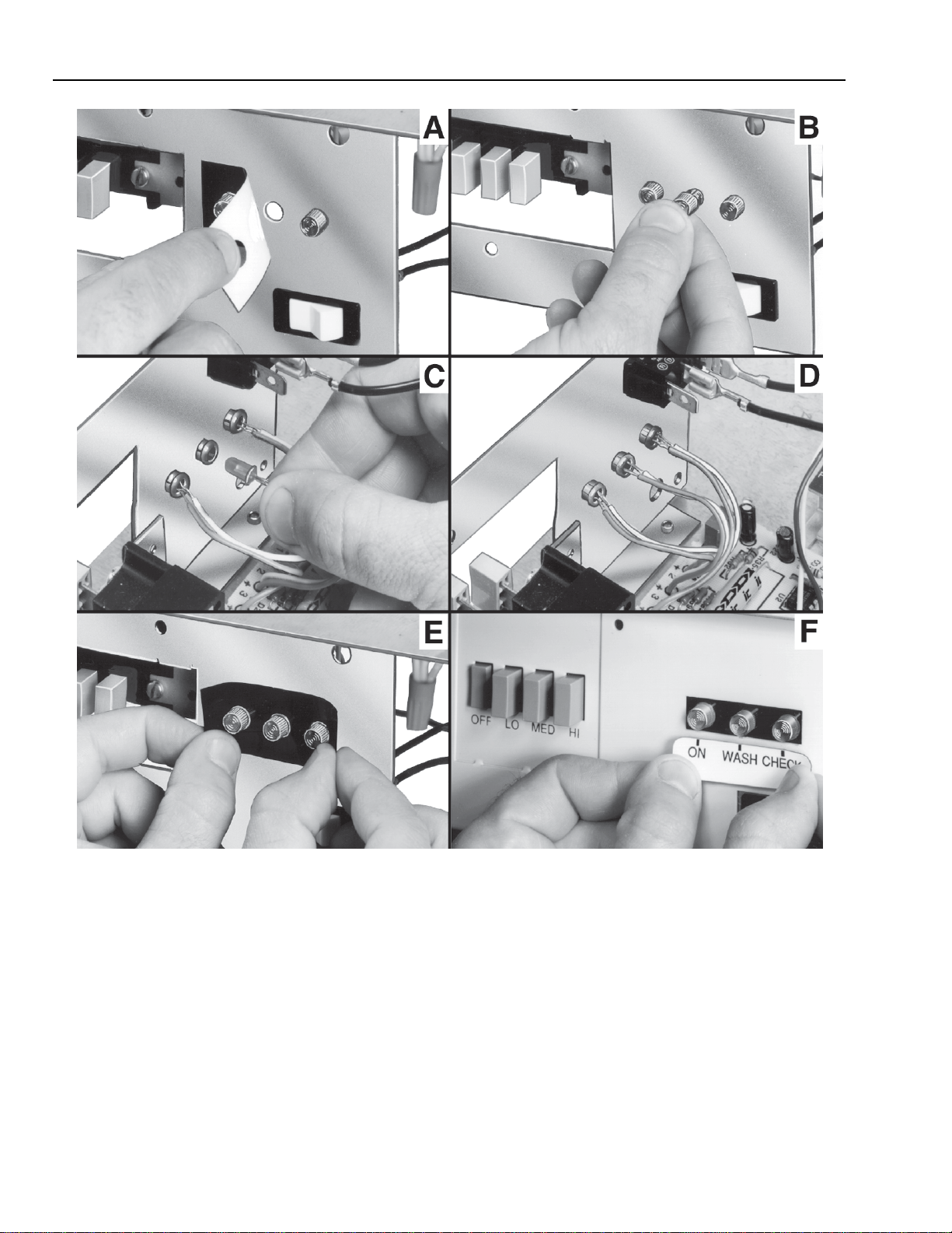
Fig. 4. Installing Optional Wash LED.
F57A,B FLUSH-MOUNTED COMMERCIAL ELECTRONIC AIR CLEANER
68-0083-9 Revised 11-08
7
INSTALLATION
When Installing this Product...
1. Read these instructions carefully. Failure to follow them
could damage the product or cause a hazardous
condition.
2. Check the ratings given in the instructions and on the
product to make sure the product is suitable for your
application.
3. If the air cleaner is to be functionally checked before
installation, be extremely careful to avoid electrical
shock. Also, take care when working near the air
cleaner’s moving arts. Ensure power is disconnected
before installation.
4. Installer must be a trained, experienced service
technician.
5. Installation and wiring must conform to current
regulations. In Europe, a qualified electrician must
supervise wiring.
6. In Europe, the air cleaner must be supplied via a
double pole isolating switch with a contact separation
of at least 3mm in each pole.
7. WARNING: This air cleaner must be earthed
(grounded).
8. This air cleaner is designated for use in commercial
premises; it is not intended for use in domestic
applications.
9. Ensure minimum fresh air supply is maintained based
on the type of premises and occupancy. Refer to local
standards and codes of practice.
10. After installation is complete, check out air cleaner
operation as provided in these instructions.
WARNING
Explosion Hazard Possible
Can cause personal injury or equipment damage.
Do not install or use the F57A,B where there is any
danger of gas, vapor, or dust explosion.
This unit has not been investigated for use in the
ceilings of fire-resistant assemblies.
CAUTION
• Do not connect the power source until after
electronic air cleaner is mounted. This will prevent
electrical shock or equipment damage.
• Be sure to turn off the air cleaner before servicing
it. The air cleaner motor is equipped with an
automatic thermal overload. If the motor becomes
overheated, it will automatically stop. It will
automatically start after a sufficient period of
cooling (several minutes to an hour).
• If the air cleaner must be turned on for an
electrical check, be extremely careful to avoid
electrical shock. Also, take care when working
near the air cleaner moving parts.
• When installing the air cleaner in the ceiling, wear
gloves for hand protection.
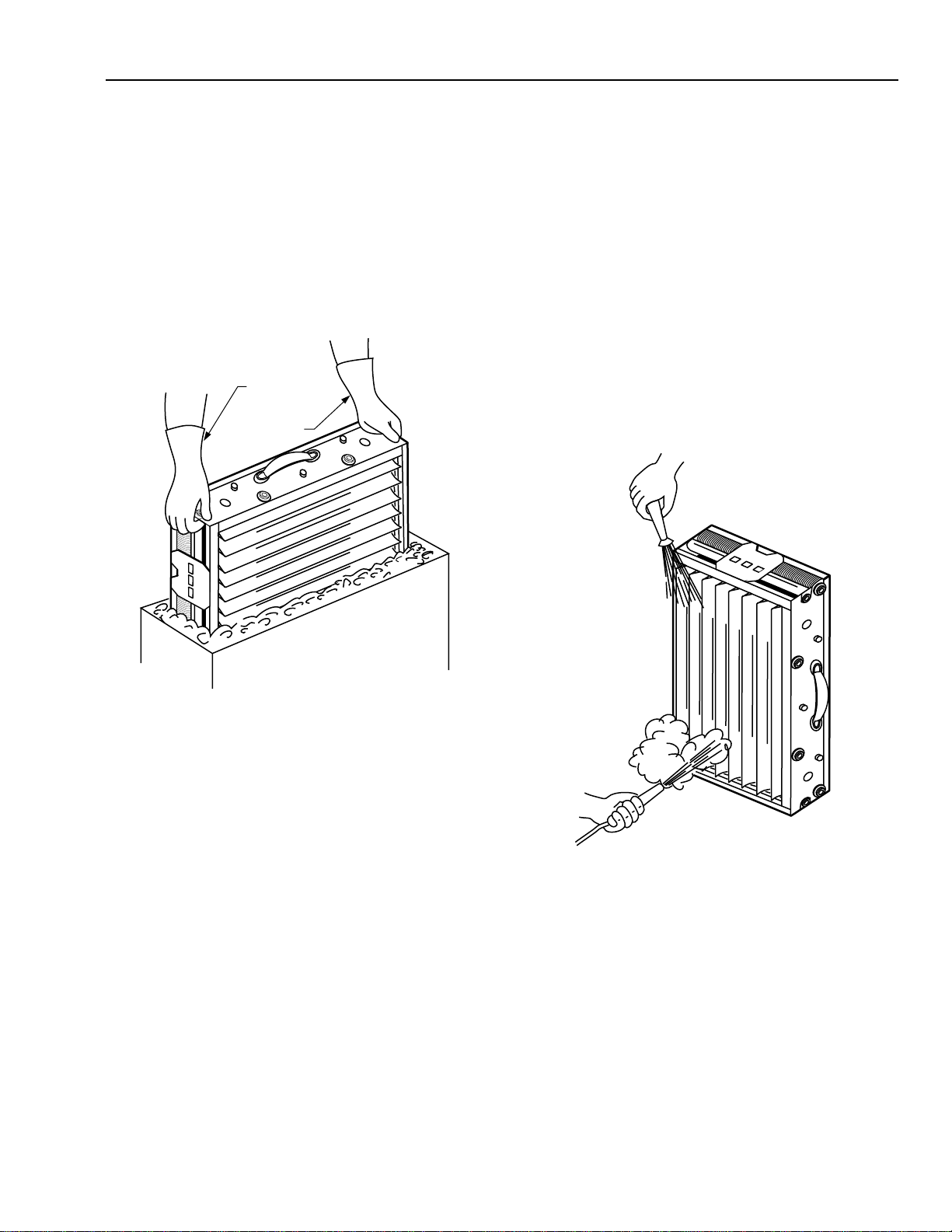
Unpack F57 Commercial
Electronic Air Cleaner
WARNING
Sharp Edges
Can cause personal injury.
Handle air cleaner carefully to avoid cuts from sharp
metal edges. Wear protective gloves.
• Remove the grille assembly.
• Remove the prefilter and electronic cells from the
electronic air cleaner; set aside.
• Remove the electronic air cleaner from the box; remove
the four screws on the back of the cleaner, and discard.
This releases the fan motor into a floating suspension that
minimizes noise.
• Remove all shipping cardboard and cell containers inside
and outside of the air cleaner components. Inspect
packing material before discarding to be sure no parts or
papers are lost.
• If installing optional WASH LED, remove power supply
cover. Refer to Fig. 4 and the corresponding steps below:
A. Remove black two-hole label from switch
bracket.
B. Snap the LED holder into the center hole,
mounting from the front side of the switch
bracket.
C./D. Snap the LED into the back of the LED holder.
E. Apply plain three-hole label included onto the
switch bracket.
F. Replace power supply cover and apply printed
label (included) to power supply cover.
Optional Exhaust Air Vent
Remove the five-inch knockout on the side of the F57 when
using the exhaust air vent option. Purchase a five-inch collar
locally and insert into the opening. Bend tabs to secure the
collar.
Mount F57 Commercial
Electronic Air Cleaner
WARNING
Heavy Equipment
Can cause personal injury or equipment damage.
When the F57A,B is not reinforced as explained below,
structural weakening, buckling, or the unit falling may
cause personal injury and equipment damage.
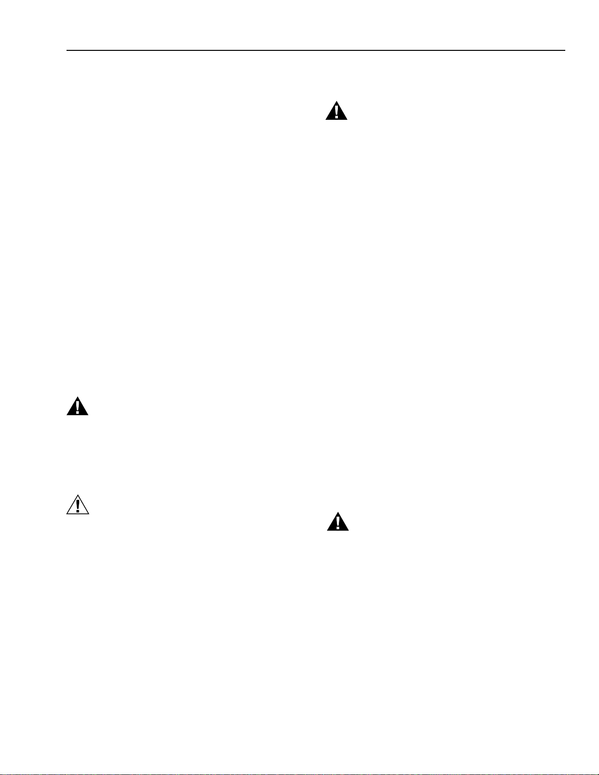
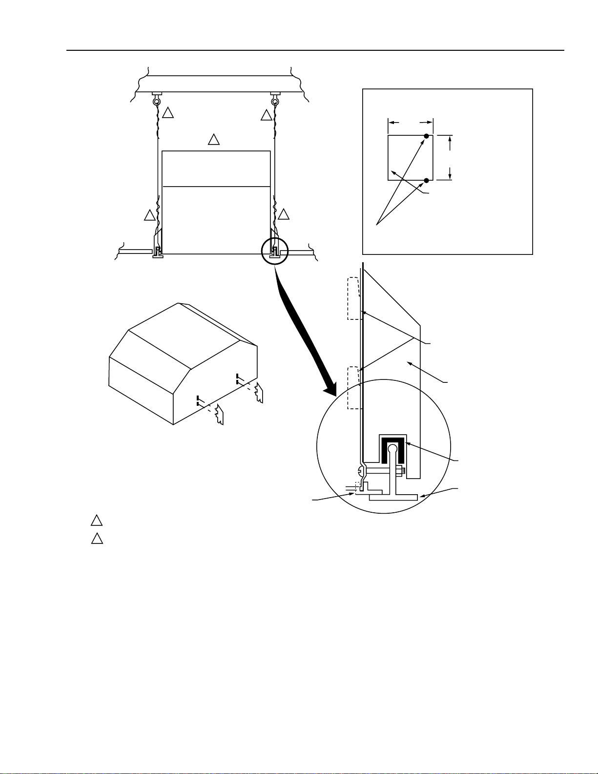
Mount the F57A,B as part of a suspended ceiling, with a
minimum of 14 in. (356 mm) between the suspended ceiling
and the true ceiling. See Figs. 5 and 6.
Forty feet (12.2m) of 12 gauge wire is included for adding
support to the dropped ceiling T-bars. Also included are four
support shoulders, four rubber mounting spacers, and four
panhead bolts with self-locking nuts.
• Remove the tile(s) from the suspended ceiling for a space
approximately 24 x 48 in. (610 x 1220 mm) for F57A, or 24 x
24 in. (610 x 610 mm) for F57B. The area between the
suspended ceiling and the true ceiling must be at least 14
in. (356 mm) and clear of ducts, pipes, and other
obstacles and encumbrances.
F57A,B FLUSH-MOUNT COMMERCIAL ELECTRONIC AIR CLEANER
68-0083-9 Revised 11-08
8
SUSPENDED
CEILING
F57A
BE SURE TO TWIST THE SUPPORT WIRE A MIINIMUM OF FOUR TIMES TO PROPERLY BEAR WEIGHT.
THERE MUST BE 14 IN. (356 MM) BETWEEN SUSPENDED CEILING AND TRUE CEILING.
SUPPORT SHOULDER
POSITIONS
REINFORCED
T-BAR
VINYL FLANGE
MOUNTING
SPACER (1 OF 4)
SUPPORT
SHOULDER
(1 OF 4)
BEND TABS TO
HOLD MOUNT
ON AIR CLEANER
PLACE WIRE SUPPORTS AS CLOSE AS POSSIBLE
TO F57A SUPPORT SHOULDER POSITIONS,
APPROXIMATELY 5 IN. (127 MM) FROM ENDS.
T-BAR/DROP CEILING SUPPORT SYSTEM
24 IN.
(610 MM)
24 IN.
(610 MM)
M5674
SUSPENDED
CEILING
TRUE CEILING
1
1
1
1
2
1
2
24 IN.
(610 MM)
IF NEEDED, REMOVE
T-BAR TO CREATE
48 X 24 IN.
(1219 X 610 MM) SPACE.
Fig. 5. Typical F57A mounting procedures.
F57A,B FLUSH-MOUNTED COMMERCIAL ELECTRONIC AIR CLEANER
68-0083-9 Revised 11-08
9
SUSPENDED
CEILING
F57B
BE SURE TO TWIST THE SUPPORT WIRE A MIINIMUM OF FOUR TIMES TO PROPERLY BEAR WEIGHT.
THERE MUST BE 14 IN. (356 MM) BETWEEN SUSPENDED CEILING AND TRUE CEILING.
SUPPORT
SHOULDER
POSITIONS
REINFORCED
T-BAR
VINYL FLANGE
MOUNTING
SPACER (1 OF 4)
SUPPORT
SHOULDER
(1 OF 4)
BEND TABS TO
HOLD MOUNT
ON AIR CLEANER
PLACE WIRE SUPPORTS AS CLOSE AS POSSIBLE
TO F57B SUPPORT SHOULDER POSITIONS,
APPROXIMATELY 1 IN. (25 MM) FROM ENDS.
T-BAR/DROP CEILING SUPPORT SYSTEM
24 IN.
(610 MM)
24 IN.
(610 MM)
M5675
SUSPENDED
CEILING
TRUE CEILING
1
1
1
1
2
1
2
IF NEEDED, REMOVE T-BAR
TO CREATE 24 X 24 IN.
(610 X 610 MM) SPACE.
F57B
Fig. 6. Typical F57B mounting procedures.
• Reinforce the suspended ceiling T-bars with the wire,
placing the wires to evenly distribute the F57 weight.
Securely attach wires to both the suspended ceiling and
the true ceiling, and to the T-bars. Twist the wire at least
four times.
• Place F57 into cleared area with grille side facing the
floor. Lift F57 into space until grille side is above
suspended ceiling level. Reach in and attach the rubber
mounting spacers to the T-bars at the mounting shoulder
locations.
• Attach four support shoulders to the F57. Bend the tab on
the mounting shoulders to secure them to the F57.
• Attach vinyl flanges to the bottom of the F57 frame to
cover any space that appears between the F57 and the
suspended ceiling.
• Settle the F57 on the mounting spacers on the reinforced
T-bars.
• Locate the holes just above the four vinyl flanges. Drill
1/4-in. (6.4 mm) holes through the T-bars at these
locations. Slip a panhead bolt through each hole, and
fasten with a self-locking nut.
F57A,B FLUSH-MOUNT COMMERCIAL ELECTRONIC AIR CLEANER
68-0083-9 Revised 11-08
10
KNOCKOUT KNOCKOUT
FIELD SUPPLIED
DAMPER
M7640
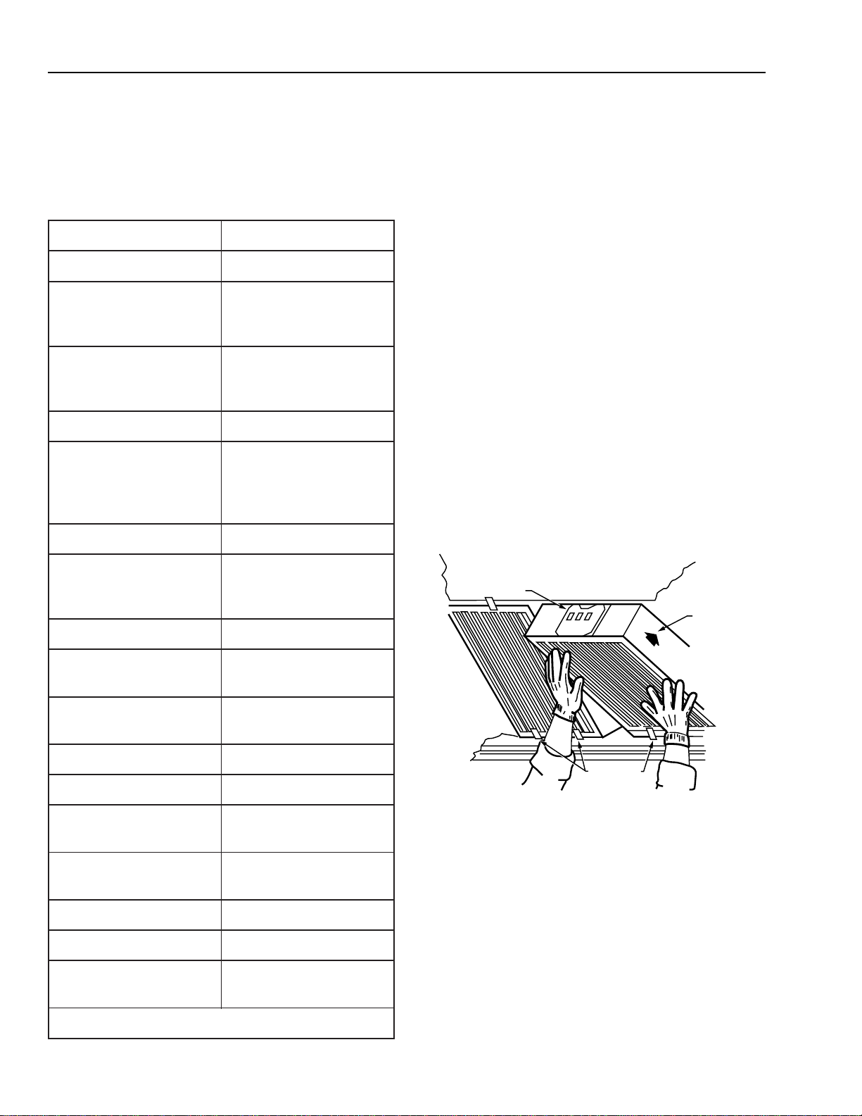
Air Vent
The air vent helps to control gaseous contaminants such as
by-products of cigarette smoking by allowing some of the air
circulated through the F57 to be discharged into the return
plenum.
To use the air vent, remove the five inch knockout in the side
of the F57 cabinet. See Fig. 7. When venting into the false
ceiling cavity, leave the vent fully open. When ducting into the
return plenum, install damper and position it to reduce the
opening by 50 percent.
Fig. 7. Air vent adjustment.
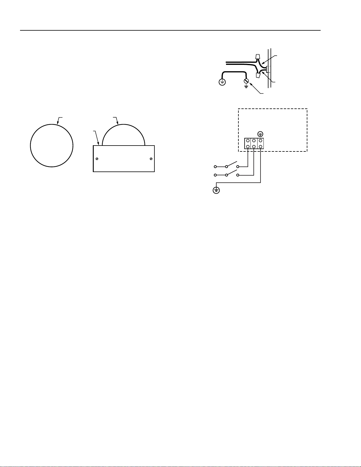
Wiring
IMPORTANT
Before wiring the F57, remove the power supply
cover. After completing the wiring procedures,
reattach the power supply cover.
All wiring must comply with applicable codes and ordinances.
The power source to the F57A,B must agree with the model
type, either 120 Vac, 60 Hz or 220–240 Vac, 50 Hz.
To wire 120 Vac, 60 Hz model:
• Run three No. 14 color-coded wires through the conduit to
the wiring compartment of the F57. Attach the green wire
to the external ground. The black and white wires are the
power carriers.
• Attach the conduit to the knockout desired (either the
large or small knockout).
• Attach the green ground wire to the ground screw. Ground
the F57 for proper operation and safety.
• Attach the black and white wires to the black and white
wires from the F57 using the wire nuts. See Fig. 8.
To wire 220–240 Vac, 50 Hz model, see Fig. 8.
IMPORTANT
Earth (ground) the F57 for proper operation and
safety.
120VAC, 60 HZ MODEL
BLACK FROM F57
WHITE FROM F57
BLACK
WHITE
120VAC
F57 GROUND SCREW
220-240VAC, 50 HZ MODEL
F57A / F57B
N
N
L
L
220-240VAC
M5669A
Fig. 8. Typical F57 wiring hookups.
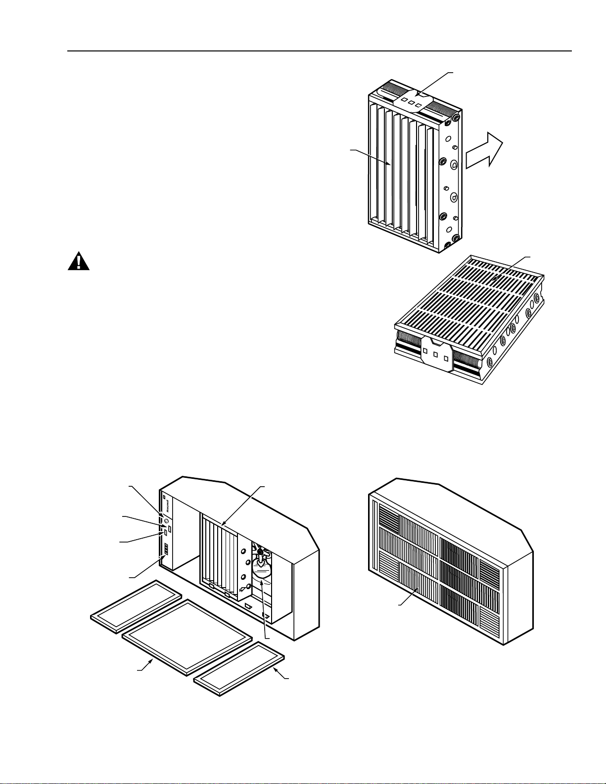
Reassemble the F57
Reinstall the electronic cells, prefilter, charcoal filter (if used)
and grille assembly. For proper installation of the cells, see
Service section.
CHECKOUT
Inspect the Installation
Refer to Figs. 9 and 10 for location of components.
• Be sure that the screws on the back of the F57 are
removed to allow for the motor floating suspension.
• Observe that the F57 is oriented for good air circulation.
• Check that the F57 is correctly and securely attached. Be
sure that the F57 weight does not overstress the
suspended ceiling.
• Make sure that the access door is easily opened, and that
the prefilter, cells, and activated carbon filters (if used) are
secure within the unit.
• Check leveling of the F57. If necessary, further reinforce
and relevel suspended ceiling T-bar grid and adjust the
hanging wires. If unit is not level, motor can be noisy or
can eventually malfunction.
• Check that the electronic cells are correctly oriented for
correct airflow. The cells are correctly oriented when the
contact board of the cell is properly seated. The ionizer
section faces the access door and the collector section
faces the fan.
F57A,B FLUSH-MOUNTED COMMERCIAL ELECTRONIC AIR CLEANER
68-0083-9 Revised 11-08
11
M5677
IONIZER
CONTACT
IONIZER
WIRES
COLLECTION
PLATES
AIR FLOW
TEST
BUTTON
PERFORMANCE
SWITCH
INDICITATOR
LEDS
FAN SPEED
SELECTION
OR IR
RECEIVER
PREFILTER
(MOUNTS
IN GRILLE)
HEAVY DUTY
COMMERCIAL CELL (2)
FAN
M5671A
F57A – GRILLE REMOVED
F57A – GRILLE REPLACED
GRILLE
OPTIONAL ACTIVATED
CARBON FILTER (2)
(MOUNTS IN GRILLE)
• Be sure the prefilter is correctly placed. The airflow arrow
on the prefilter should be pointing toward the cells.
• Check that the wiring compartment cover is correctly
reinstalled and the grille assembly is latched closed.
• Clean the inside and outside of the F57.
Check Air Cleaner Operation
• Push the test button to check the power supply. An audible
arc indicates power supply operation. The CHECK LED
lights.
• Check that the fan runs at all three speed settings and
the ON LED lights when the fan is operating.
• Check that the WASH LED (if used) lights if the cells are
removed with the grille closed and the F57 turned on.
SERVICE
WARNING
Sharp Edges
Can cause personal injury.
Wear protective gloves when handling the cells and
prefilter to avoid cuts from the sharp metal edges,
collection plates, and ionizer wires.
Hot Water, Strong Detergent
Can cause personal injury.
Wear rubber gloves, eye protection, and rubber apron
for protection.
IMPORTANT
Electronic air cleaners and components are
susceptible to damage. Be careful when working
with them to avoid equipment damage. Detergents
used for cell washing must never be acid based and
must have inhibitors to prevent cell erosion.
Fig. 9. FC37B Heavy Duty Commercial Cell.
Fig. 10. F57 components (A model shown).
F57A,B FLUSH-MOUNT COMMERCIAL ELECTRONIC AIR CLEANER
68-0083-9 Revised 11-08
12
M5667
GLOVES
PREVENT
NICKS AND
CUTS
FRAME
LATCH
CELL HOOKS
Cleaning the Commercial
Electronic Air Cleaner
The F57 removes a variety of particulate contaminants from
the air. In the process of cleaning the air, the air cleaner
cells and prefilter become dirty, and the cleaning efficiency
is lowered.
To maintain a high standard of reliability and efficiency, it is
necessary to periodically maintain the F57. Maintenance
includes cleaning the cells and prefilter and inspecting the
F57. Service is required if the F57 is damaged, performs at
substandard efficiency, measures abnormal voltages, or
when the CHECK LED lights.
Regular cleaning with an alkaline-based detergent solution is
recommended. Use a commercial or home electric
dishwasher detergent, either liquid or powder. The wash
frequency is determined by the dirt level in the air. Actual
experience or optional WASH LED dictates the period
between cleanings.
If the optional WASH LED is connected and the WASH LED
comes on, a cell washing is overdue. Frequently wash the
cells and wipe any material buildup off the ionizer wires. This
prevents the wash led from coming on.
When washing with alkaline detergent results in excessive
buildup of collected dirt in the cells, do an extended cell
soaking. If buildup is still present, use high pressure water, or
air or steam cleaning. Some full-service distributors provide a
regular cleaning service to commercial establishments.
Opening the Grille
CAUTION
• Turn off power to the F57.
• Stand on a stable platform when working with the
F57.
The F57 grille can be opened by moving the spring clips
toward each other.
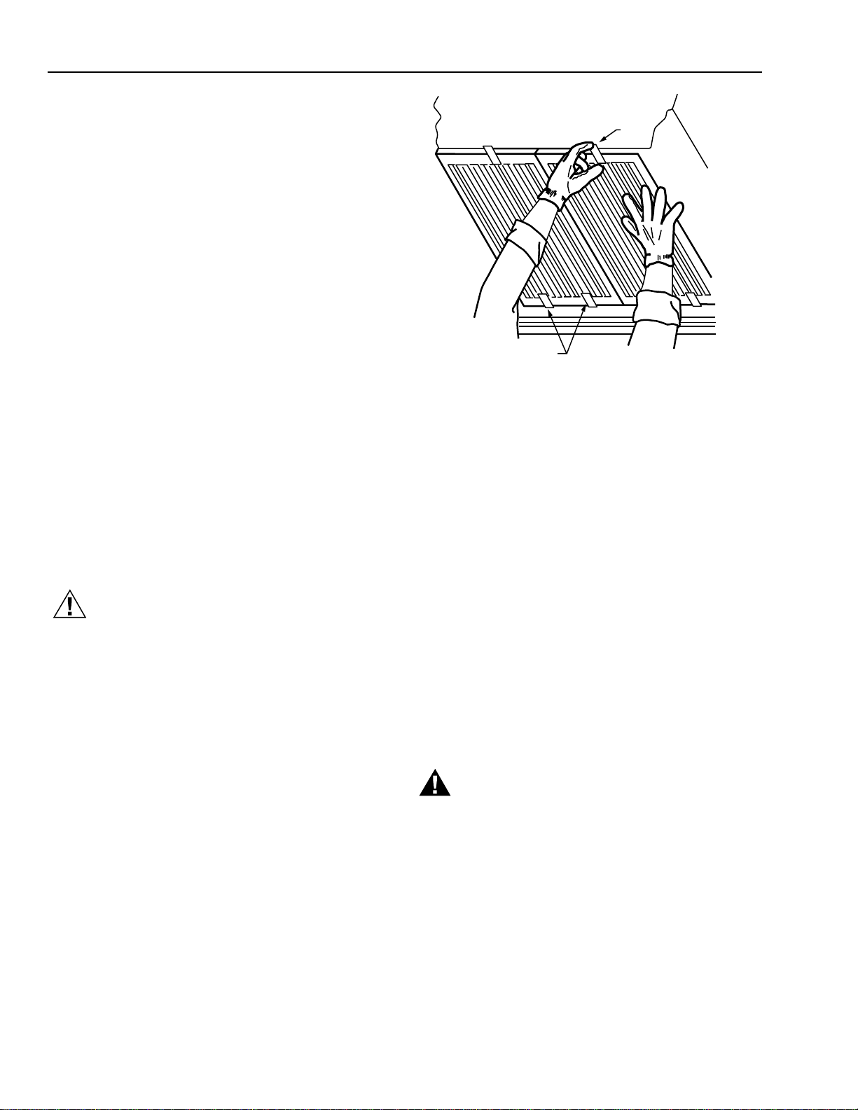
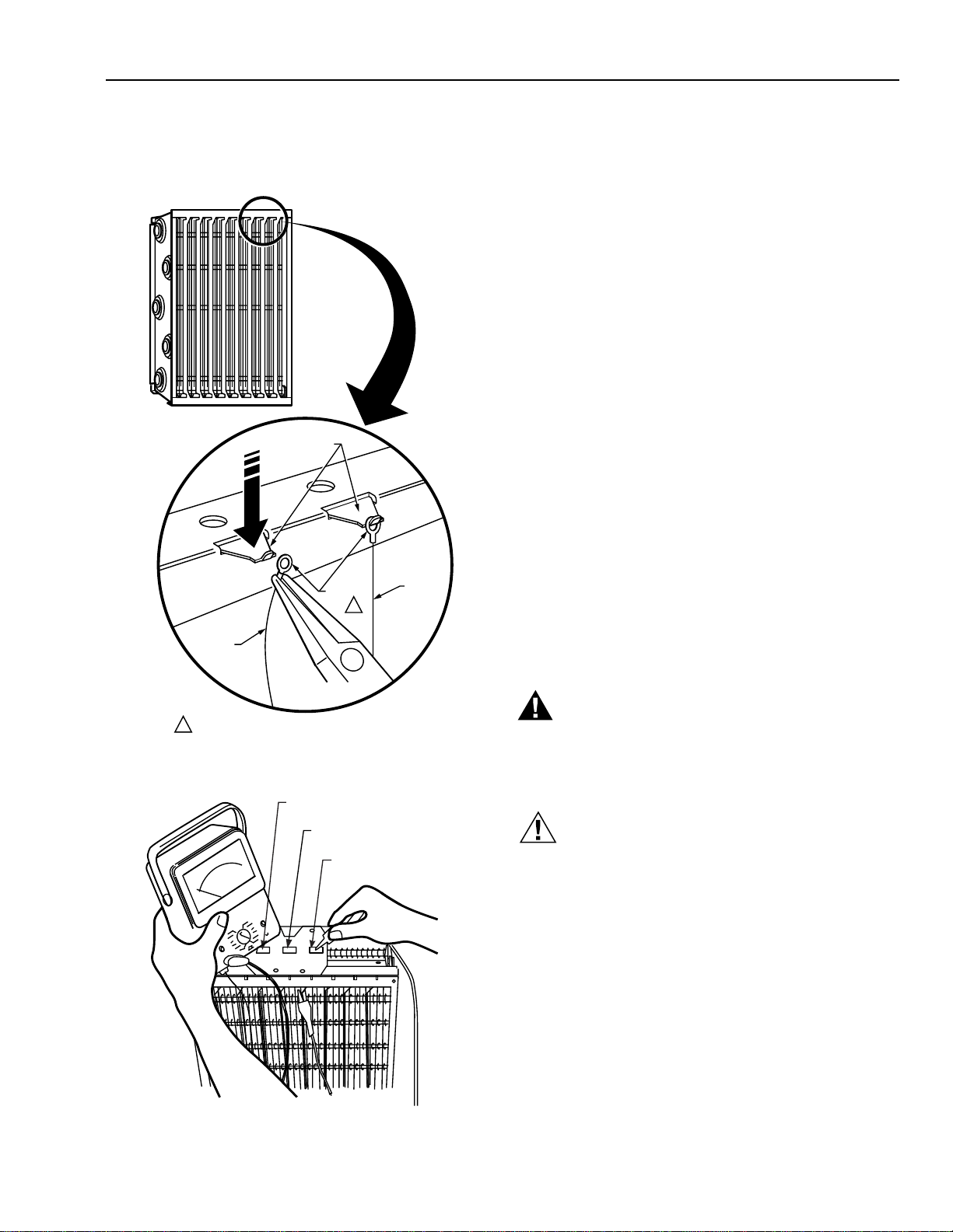
Removing the Heavy Duty
Commercial Cells and Prefilter
Remove the FC37B cells from the F57 as follows (Fig. 11):
• Turn off electrical power to the F57. Open the grille.
IMPORTANT
The cell swings down when unlatched.
• With one hand supporting the cell near the latch, rotate
the latch to an open position.
• Gently lower the cell with both hands until the cell contact
board is clear of the frame.
• Raise cell off hooks to free the cell.
Fig. 11. Removing the FC37B Heavy Duty
Commercial Cell (F57A model shown).
• Remove the prefilter from inside the grille.
• Remove the activated carbon filters, if used, only
if it must be replaced. The odor removal effectiveness is
reduced when the carbon is saturated with tobacco tar or
other gaseous contaminants and can require replacement.
Cleaning the Prefilter
• Shake out or vacuum the accumulated contaminants from
the prefilter. The prefilter can also be soaked in the
alkaline detergent solution, as described for cleaning cells
in the next section. When cleaning the prefilter, do not
soak in an acid detergent solution, or use high pressure
water, air or steam cleaning.
NOTE: When cleaning the prefilter, wash it after the cells
are washed. The lint residue from the prefilter
contaminates the wash water and can deposit inside
the cells. Dispose of the wash water.
Cleaning the Cells Using
Alkaline Base Detergent
WARNING
Hazardous Chemical.
Can cause personal injury.
• Use eye protection to prevent splashing the
detergent solution in your eyes.
• Wear rubber gloves to avoid prolonged skin
contact with the detergent.
• Keep detergent solution out of the reach of
children.
F57A,B FLUSH-MOUNTED COMMERCIAL ELECTRONIC AIR CLEANER
68-0083-9 Revised 11-08
13
M922A
WEAR GLOVES
TO PROTECT
HANDS FROM
DETERGENT
SOLUTION.
HIGH VELOCITY
DETERGENT SPRAY
STEAM
M677B
• Provide a large enough container, such as a laundry tub
or plastic tank, to hold at least one cell.
• Mix alkaline base detergent, such as commercial or home
electric dishwashing detergent (either liquid or powder)
with hot water. Follow the instructions on the detergent
package. The water temperature should be between
150°F and 190°F (66°C and 88°C). When using a cold
water detergent, follow instructions included with the
detergent.
NOTE: Be sure to avoid prolonged skin contact with the
solution. Do not splash solution in eyes.
• Soak the cells in the solution for up to 15 minutes; agitate
the cells up and down. See Fig. 12.
Fig. 12. Agitate the cells in the water.
• Remove the cells from the detergent solution; spray with
hot water as a prerinse, if desired and place cells in
another container of clear hot water (150°F to 190°F
[66°C to 88°C]) for final rinsing. Rinse the cells for five to
ten minutes.
• Remove the cells from the rinse water. Allow the cells to
drain and dry before energizing them. For optimum water
drainage from tubes, stand the cell on one of its corners.
• Wipe ionizer wires to remove any deposits remaining on
the wires.
• Check the collection plates of the cells for any detergent
residue. Repeat the rinse process if there is any residue
remaining. Buildup can reduce the F57 efficiency.
About Discolored Aluminum
Occasionally, the cell or prefilter can seem stained after the
soaking process. When the stain is black or very dark, it is
probably dirt residue and the cell should be rewashed. White
detergent residue can also affect the F57 efficiency and
should be rinsed off. When yellowing appears, it is probably
staining from tobacco smoke or other airborne dirt.
Moderate discoloration does not affect the F57 efficiency.
Cleaning the Cells Using Air
Pressure, Water Pressure or Low
Pressure Steam
The following alternative methods can be used to clean some
contaminants from the F57 cells. See Fig. 13. To prevent
damage to the prefilter, do not use pressure or steam
methods on the prefilter.
• High Pressure Air or Water. Care should be taken to avoid
damage to the cells. If detergent is required with the high
pressure water, use an alkaline base detergent. Do not
use an acid detergent.
• Steam. Extreme care must be taken when steam cleaning
to avoid warping or bending the collector plates of the
cells. Remember that the cells are hot after steam
cleaning and care must be taken to avoid burns. Use only
low pressure or wet steam.
NOTE: Do not use steam at pressure greater than 5 psi
(35 kPa) or temperature hotter than 250°F (121°C).
Fig. 13. It can be necessary to steam or use high pressure
to remove collected cells contamination.
F57A,B FLUSH-MOUNT COMMERCIAL ELECTRONIC AIR CLEANER
68-0083-9 Revised 11-08
14
CONTACT BOARD
AIRFLOW
ARROW
GLOVES
PREVENT
NICKS
AND CUTS
CELL HOOKS
M5668
Removing Specific Contaminants
from Cells
The following list gives the appropriate cleaning procedure
for types of contamination often found on cells and prefilters.
Cleaning procedures are listed in order of preference. Be
careful to avoid bending the cell collector plates.
Reinstalling the Cells, Prefilter and
Activated Carbon Filters, If Used
• Inspect the cells for broken ionizer wires and bent collector
plates. Bend warped or bent collector plates back into
shape. For maximum efficiency, replace broken ionizer
wires as instructed in Replacing Ionizer Wires section.
• Wipe ionizer wires.
• Check that cells are completely dry before reinstalling in the
air cleaner. If cells are placed into the air cleaner while still
wet, the electronic cells can short out and arc frequently
when almost dry. Although the system appears to be oper-
ating, the cells may not be cleaning during the drying period.
• Be sure the contact board of the cell is facing the latch side
of the frame.
• Check that the airflow arrow is pointing toward the fan. In
this position, the ionizer wire side of the cell is the farthest
from the fan.
• Ease the edge of the cell into the cell hooks.
• Using both hands, pivot the cell until the contact board
mates with the frame.
• With one hand supporting the cell near the latch, rotate the
latch to a closed position. See Fig. 14.
• Wipe surface dirt from the inside and the outside
of the grille.
• Replace the prefilter in the grille. Be sure that the airflow
arrow is pointing toward the cells.
• Replace activated carbon filters, if used. The F57A carbon
filters fit inside the grille, one on each side of the prefilter.
The F57B carbon filter fits inside the grille on the left side of
the prefilter.
• Close and carefully latch the grille.
Fig. 14. Reinstalling the cell.
Replacing Ionizer Wires
Broken or bent ionizer wires can cause an electrical short to
ground, often resulting in visible arcing or sparking. Remove
broken wires. Cells can be used temporarily with one wire
missing, but replace the wire as soon as possible.
Replacement wires, part no. 136434AA, are cut to length with
eyelets on both sides for easy installation. To install:
1. Hook the eyelet on one end of the wire over the spring
connector on one end of the cell. See Fig. 15. Be careful
to avoid damaging the spring connector or other parts
of the cell.
2. Hold the opposite eyelet with a needlenose pliers and
stretch the wire the length of the cell. Depress the
opposite spring connector and hook the eyelet over it.
tnanimatnoCerudecorPgninaelC
noitulosriahlaminAtnegretedrehsawhsiD
nobraC
pmal,toos,kcalbnobrac(
)tsudlaocr
ahc,etihparg,kcalb
noitulostnegretedrehsawhsiD
ro*riaerusserphgih
*retawerusserphgih
:sliognikooC
)tunaep,
naebyoS(elbategeV
)rettub,dral(laminA
noitulostnegretedrehsawhsiD
*maetsro
noitulossrebifnottoCnoitulostne
gretedrehsawhsiD
tsuD
muiclac,edixoidnocilis(
epytlarenimdna,etanobrac
)sdnuopmoc
noitulostnegretedrehsawh
siD
tsudruolFnoitlulostnegretedrehsawhsiD
liolareniM
dnasretseid,esabmuelortep(
)enocilis
noitulostnegreted
rehsawhsiD
*retawerusserphgihro
stcudorprepaPnoitulostnegretedrehsawhsiD
tniaP
)esabretawroesablio(
noitulo
stnegretedrehsawhsiD
sniserrateniP
noitulostnegretedrehsawhsiD
*maetsro
spaoSnoitulostnegretedrehsawhsiD
ed
irolhcmuidoSnoitlulostnegretedrehsawhsiD
sraguS
)sessalomgnidulcnisepytlla(
noitulostnegretedrehsawhsiD
*m
aetsro
claT
ro*riaerusserphgiH
noitulostnegretedrehsawhsiD
ekomsdnasratoccaboTnoitulostnegretedrehsawhsiD
s
ehsinraVnoitulostnegretedrehsawhsiD
)sepytlla(sexaW
noitulostnegretedrehsawhsiD
*maetsro
.sretliferpnaelco
tesutonoD*
F57A,B FLUSH-MOUNTED COMMERCIAL ELECTRONIC AIR CLEANER
68-0083-9 Revised 11-08
15
Modification to Reduce Ozone
Odor
The electronic air cleaner generates a trace amount of
ozone in normal operation. During the first week or two of
operation, the amount may be higher because of sharp
edges on some of the new high voltage metal parts.
However, normal use and the first wash quickly dull the
edges.
The average person can detect the odor of ozone indoors in
concentrations as low as 0.003 to 0.010 parts per million
(ppm). The electronic air cleaner contributes 0.005 to 0.010
ppm of ozone to the indoor air. The U.S. Food and Drug
Administration and Health and Welfare Canada recommend
that indoor ozone concentration should not exceed 0.050
ppm. As a comparison, the outdoor ozone level in major
cities ranges from 0.020 ppm to 0.040 ppm and even higher.
However, if desired, the ozone generated by the air cleaner
can be reduced in one of two ways:
1. Install the optional activated carbon filter.
2. Open the grille and move the electronic air cleaner
performance switch to the low setting. Close and
relatch the grille. The cleaning efficiency is now
reduced 5 to 15 percent, depending on airflow.
NOTE: Be sure the switch is set to either high or low
position, not between or the unit may not run.
Be careful not to reset the switch when closing
the cover.
ELECTRICAL
TROUBLESHOOTING
WARNING
Electrical Shock Hazard
Can cause personal injury or equipment damage.
The following procedures expose hazardous live
parts. Disconnect power supply between checks and
proceed carefully.
CAUTION
The following instructions are for use by only qualified
personnel.
Tools and Equipment
Troubleshooting the electronic air cleaner requires:
• Needlenose pliers for stringing ionizer wires and inserting
edge connectors.
• Test meter with 15 kV dc probe.
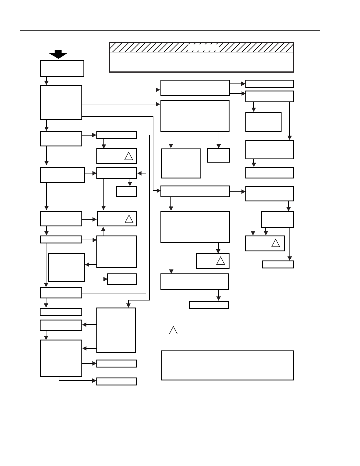
Troubleshooting Procedure
The electronic air cleaner Troubleshooting chart, Fig. 17
shows how to quickly isolate a problem in the air cleaner.
See Figs. 18 & 19 for electrical schematics.
M1540B
IONIZER
WIRE
IONIZER
WIRE
NEEDLENOSE
PLIERS
SPRING
CONNECTORS
PRESS
DOWN
EYELETS
REPLACING AN IONIZER WIRE.
TWO EYELETS HOLD IONIZER WIRE TO CELL.
1
1
COLLECTOR
TERMINAL
COLLECTOR
TERMINAL
IONIZER
TERMINAL
M6155
3. Check the cell for short circuits using an ohmmeter. See
Fig. 16. Check the resistance between the frame of the
cell and both the ionizer and the collector contacts. In
each case, the resistance should be infinite.
Fig. 15. Install new ionizer wire by hooking
eyelets over spring connectors.
Fig. 16. Use an ohmmeter to check
the cells for short circuits.
F57A,B FLUSH-MOUNT COMMERCIAL ELECTRONIC AIR CLEANER
68-0083-9 Revised 11-08
16
START
LED ON/FAN ON
NO
YES
YES
YES
NO
DAMAGED
"ON" LED OFF/FAN OFF
"ON" LED ON/FAN OFF
"ON" LED OFF/FAN ON
NO
NO
NO
YES
NO
YES
NO
YES
NO
YES
YES
NO
NO
YES
YES
YES
FAN
OFF
FAN
ON
YES
YES
CELL
SHORTED
INFINITE RESISTANCE
NO
YES
YES
ELECTRONIC COMPONENTS ON POWER SUPPLY BOARDS ARE
NOT FIELD REPLACEABLE. ATTEMPTED SERVICE WILL DAMAGE
BOARDS . IF TROUBLESHOOTING INDICATES A POWER SUPPLY
PROBLEM, REPLACE THE ENTIRE POWER SUPPLY ASSEMBLY.
TO USE THIS CHART:
1. FOLLOW THE STEPS IN THE EXACT SEQUENTIAL ORDER.
2. EACH TIME YOU ISOLATE AND FIX A PROBLEM, GO BACK TO START.
3. REPEAT ALL THE STEPS UNTIL THE AIR CLEANER CHECKS OUT OK.
NO
NO
MAKE SURE CELLS
ARE CLEAN, DRY, AND
PROPERLY INSTALLED.
CLOSE COVER OR
DEFEAT INTERLOCK.
TURN ON AIR
CLEANER . CHECK
FAN OPERATION AT
LO, MED, HI SPEEDS.
OBSERVE "ON'' LED.
PUSH TEST BUTTON.
LISTEN FOR
SNAPPING SOUND.
HOLD DOWN TEST
BUTTON. IS
"CHECK" LED LIT?
RELEASE TEST
BUTTON. IS
"CHECK" LED LIT?
IS "WASH" LED LIT?
TURN OFF AIR
CLEANER. SHORT
IONIZER TO FRAME
WITH TEST LEAD.
TURN ON AIR
CLEANER. IS
"WASH" LED LIT?
CLEAN CELLS,
WIPING IONIZER
WIRES. INSPECT
CELLS FOR
DAMAGED IONIZER
CONTACTS.
REPLACE OR
REPAIR CELLS.
REMOVE CELLS. IS
"WASH" LED LIT?
AIR CLEANER OK.
REPAIR OR REPLACE
CELL(S)
WITH OHMMETER,
CHECK FOR SHORT
BETWEEN:
- CELL FRAME AND
COLLECTOR
TERMINAL.
- CELL FRAME AND
IONIZER TERMINAL.
IS "CHECK" LED LIT?
CHECK INPUT
VOLTAGE TO LED.
REPLACE
LED.
REPLACE
POWER
SUPPLY.
INSPECT CELLS FOR:
- BENT COLLECTOR
PLATES
- BROKEN IONIZER
WIRES
- DIRT ON
INSULATORS
- DAMAGED IONIZER
OR COLLECTOR
CONTACT TABS
REPLACE CELLS
NO
CELLS OK.
REPLACE SWITCH.
CHECK INPUT VOLTAGE
TO INTERLOCK SWITCH.
TURN OFF AIR CLEANER. OPEN
COVER. DEFEAT INTERLOCK. CHECK
FOR INPUT VOLTAGE TO SWITCH.
CHECK WIRING BACK
THROUGH POWER CORD
AND OUTLET TO CIRCUIT
BREAKER OR FUSE.
CORRECT WIRING
OR FUSING.
ADJUST/REPAIR/
REPLACE
INTERLOCK
SWITCH.
TURN OFF AIR CLEANER. OPEN
COVER. REMOVE ACCESS PANEL.
DEFEAT INTERLOCK. TURN ON AIR
CLEANER. JUMPER SWITCH
CONTACTS FOR EACH SPEED
IN TURN.
REPLACE
SWITCH.
HOLD DOWN TEST
BUTTON ; DOES
"CHECK" LED LIGHT?
CHECK FOR
VOLTAGE
TO "ON" LED.
REPLACE
POWER
SUPPLY.
REPLACE LED.
REPLACE
POWER
SUPPLY.
TURN OFF UNIT. OPEN COVER.
REMOVE ACCESS PANEL. DEFEAT
INTERLOCK. TURN ON AIR
CLEANER. CHECK FOR CORRECT
INPUT VOLTAGE TO POWER
SUPPLY: CHECK BOARD
TERMINALS P1 AND P2.
PUSH TEST BUTTON. LISTEN
FOR SNAPPING SOUND.
CHECK WIRING BACK THROUGH
SWITCH, INTERLOCK, POWER CORD,
OUTLET, AND CIRCUIT BREAKER.
CORRECT WIRING.
M3665B
TURN OFF POWER.
MAKE SURE FAN
MOTOR ROTATES
FREELY. REPLACE
FAN MOTOR IF
NECESSARY.
1
1
1
NO
1
REPLACE
POWER
SUPPLY.
1
NO
RISK OF ELECTRIC SHOCK
THESE SERVICING INSTRUCTIONS ARE FOR USE BY QUALIFIED PERSONNEL ONLY. TO REDUCE RISK
OF ELECTRIC SHOCK, DO NOT PERFORM ANY SERVICING OTHER THAN CONTAINED IN THE
OPERATING INSTRUCTIONS UNLESS YOU ARE QUALIFIED TO DO SO.
WARNING
Fig. 17. Electrical troubleshooting procedure for the F57A,B.
F57A,B FLUSH-MOUNTED COMMERCIAL ELECTRONIC AIR CLEANER
68-0083-9 Revised 11-08
17
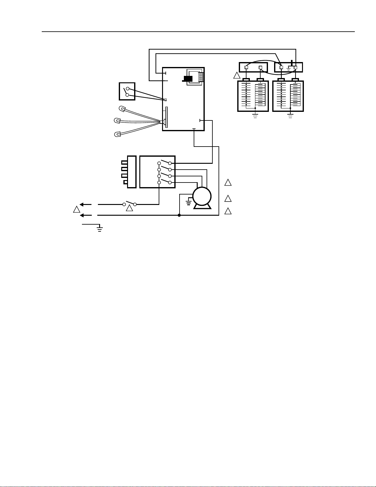
P3
P4
P1
P2
1
RED IONIZER
BLACK COLLECTOR
1 POWER SUPPLY. PROVIDE DISCONNECT
MEANS AND OVERLOAD PROTECTION
AS REQUIRED.
2 LEFT CELL AND CONTACT BOARD ON
TWO-CELL AIR CLEANER ONLY.
3 INTERLOCK SAFETY SWITCH.
M10652
POWER
SUPPLY
2
BLACK
RED
TEST
BUTTON
CONTACT
BOARD
BROWN
VIOLET
BLUE
RED
ON
HI
MED
LO
HI
MED
LO
OFF
FAN
MOTOR
3
PERFORMANCE
SWITCH
BLACK
BLACK
WHITE
ORANGEBLACK
L1
(HOT)
L2
GROUND
PUSH BUTTONS WIRING TERMINALS
ON-OFF/3-SPEED FAN SWITCH
CHECK
(RED)
WASH
(YELLOW)
WHITE
RED
WHITE
RED
WHITE
RED
ON
(YELLOW)
J5
Fig. 18. F57A,B 120V model electrical schematic.
F57A,B FLUSH-MOUNT COMMERCIAL ELECTRONIC AIR CLEANER
68-0083-9 Revised 11-08
18
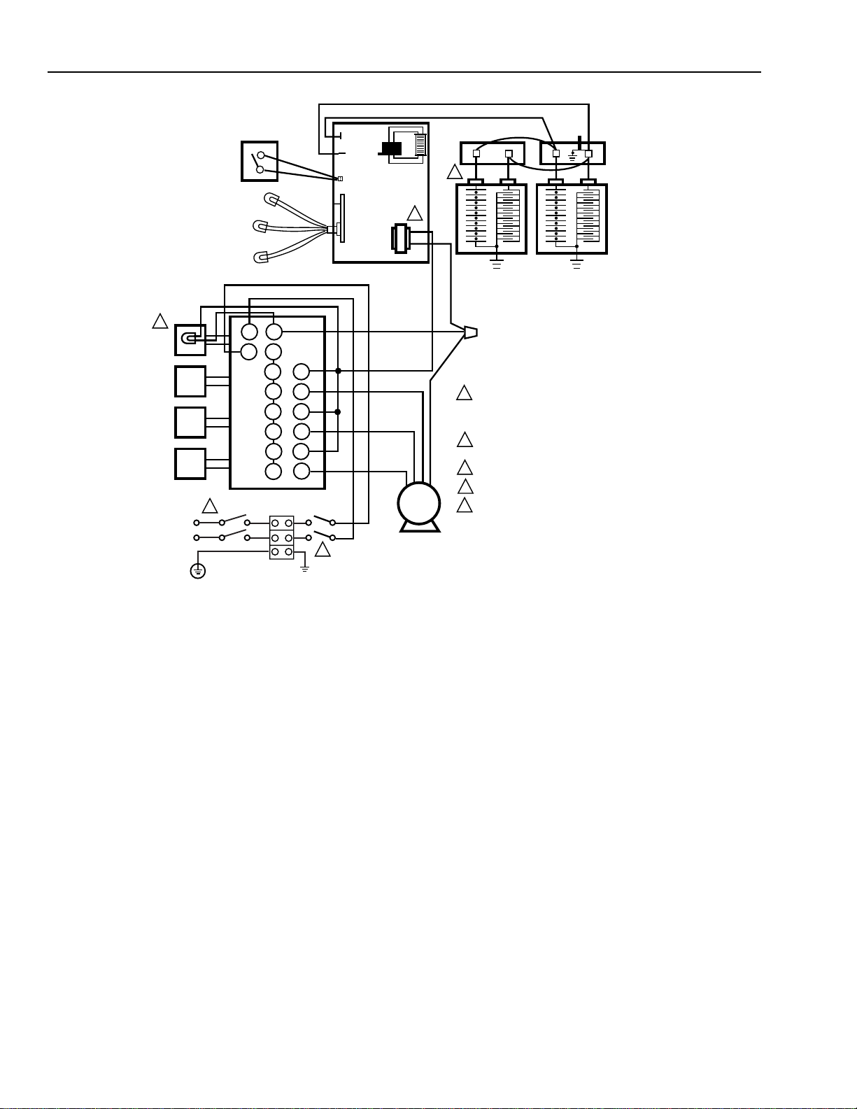
Fig. 19. F57A,B 220–240V model electrical schematic.
1
1 TERMINAL BLOCK FOR POWER SUPPLY
CONNECTIONS. PROVIDE DISCONNECT
MEANS AND OVERLOAD PROTECTION
AS REQUIRED.
2 BROWN LEAD MUST BE CONNECTED TO TOP
TERMINAL ON TRANSFORMER.
3 INTERLOCK SAFETY SWITCH.
4 PROVIDES ON-OFF INDICATION.
5 LEFT CELL AND CONTACT BOARD ON
TWO-CELL AIR CLEANER ONLY.
M10653A
5
BLACK
RED
TEST
BUTTON
CONTACT
BOARD
BROWN
VIOLET
BLUE
RED
FAN
MOTOR
3
WHITE
A3
A4
B3
B4
C3
C4
D3
D4
A5
A6
B1
B2
C1
C2
D1
D2
OFF
LO
MED
HI
ORANGE
BLACK
ON-OFF/3-SPEED
FAN SWITCH
WHITE
WHITE
4
RED IONIZER
BLACK COLLECTOR
LAMP
P3
P4
POWER
SUPPLY
2
PERFORMANCE
SWITCH
BLACK
BLACK
CHECK
(RED)
WASH
(YELLOW)
WHITE
RED
WHITE
RED
WHITE
RED
ON
(YELLOW)
J5
N
L
220-240VAC
F57A,B FLUSH-MOUNTED COMMERCIAL ELECTRONIC AIR CLEANER
68-0083-9 Revised 11-08
19
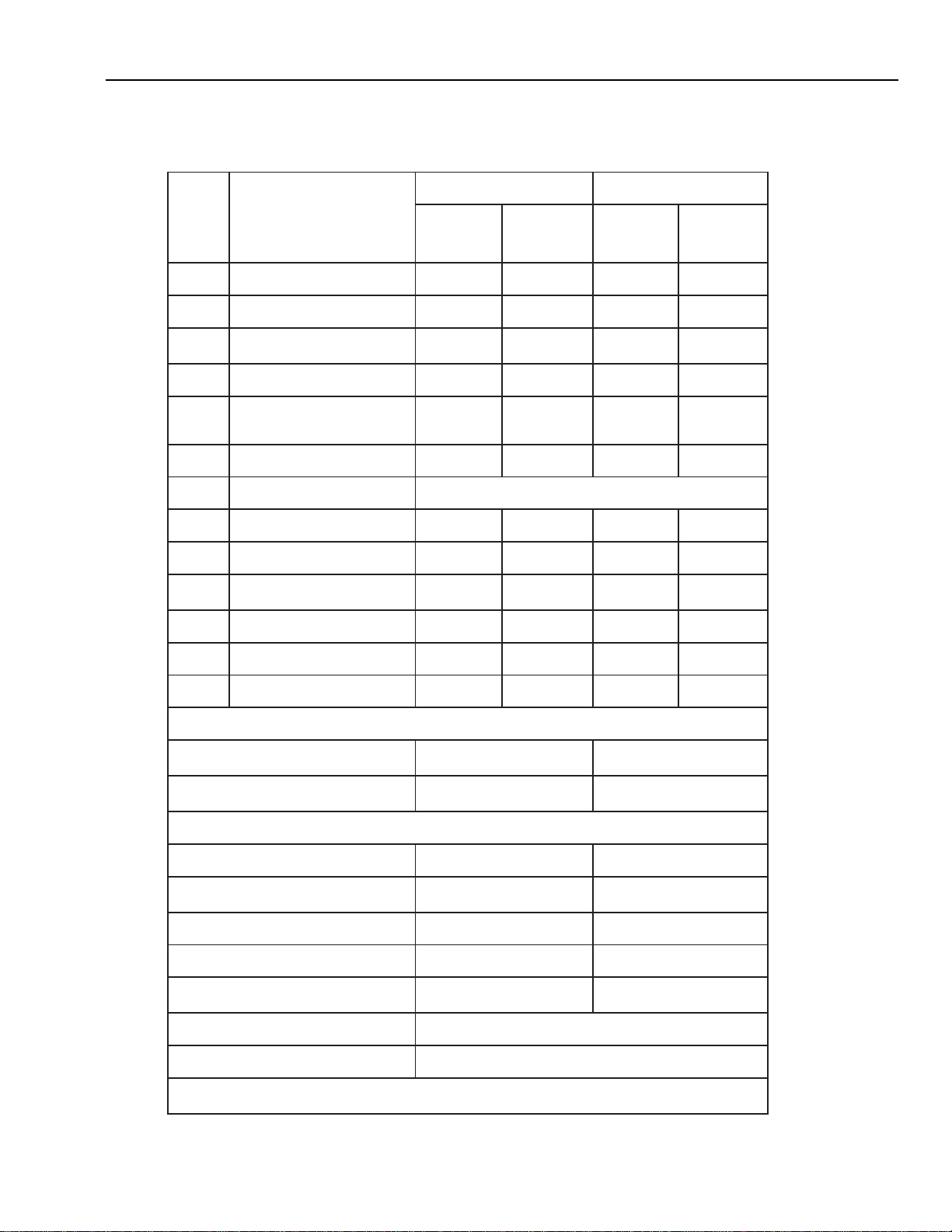
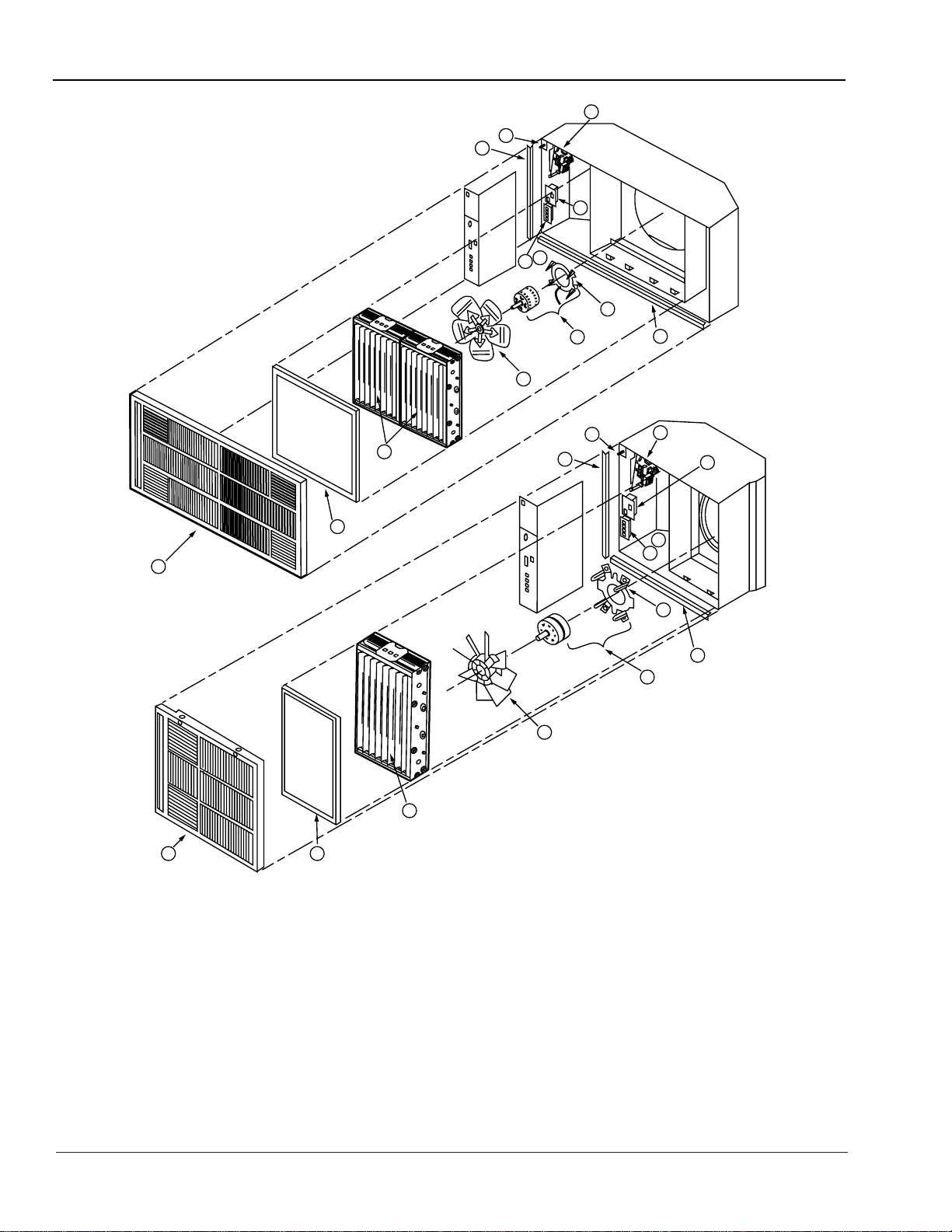
PARTS LIST
See Fig. 20 for exploded view of parts listed.
.giF
.feR
.oN
noitpircseD
rebmuNtraPA75FrebmuNtraPB75F
,caV021
zH06
ledoM
042/022
05,caV
ledoMzH
,caV021
zH06
ledoM
042/022
05,caV
ledoMzH
1ylbmessAellirGB114691B114691A463022A463022
2retliferP019591019591175891175891
3
lleClaicremmoCytuDyvaeH
)B75Fno1,A
75Fnoowt(
0301B73CF
)2(
0301B73CF
)2(
0301B73CF0301B73CF
4naF502691502691393022393022
5
sedulcni(ybmessArotoM
ruof,t
ekcarbrotom,rotom
)sgnihsubnoitalosi
A512691A612691A376891A318002
6hctiwSlortnoC283091439691283091439691
a6*reviec
eRderarfnI**A409302
7hctiwSecnamrofreP412691412691412691412691
8hctiwSkcolretnI176891722691176891722691
9ylbmessAylp
puSrewoP
A163302
*C724802
B163302
Q724802
C163302
*K724802
D163302
T724802
01)2(spirtSlyniV051691314691051691314691
11)2(spirtSlyniV151691414691156891156891
21tekcarBrotoM1970202197020219702021970202
)NWOHSTON(DEDULCNISTRAPNOITAL
LATSNI
roftinurepderiuqerruof(stnuoMredluohS
)gnignah
331691331691
,A75Fnoowt(srecapSgnitnuoMrebbuR
)B75Fno
eno
431691431691
)NWOHSTON(SEIROSSECCALANOITPODNASTRAP
ylbmessAgaBDELHSAWHME4704HME4704
,A75Fnoowt(ylbmessAd
raoBtcatnoC
)B75Fnoeno
A219091A219091
)eviffospuorgniredro(eriWrezinoIAA434631AA434631
retliFnobraC)2(11959127
6891
rof(ylbmessAlortnoCetomeRderiwdraH
)ylnOledoMcaV021
C790091C790091
**tiKrettimsnarT/revieceRderarfnI 4
063
tiKetalPrevoCetomeRderarfnI75F MA5063
.eporuEnielbaliavatoN*
deifitreC).L.U(baLs'retirwrednUtoN**
F57A,B FLUSH-MOUNT COMMERCIAL ELECTRONIC AIR CLEANER
68-0083-9 Revised 11-08
20
M10651
F57B
1 2
3
4
5
11
12
10
8
9
F57A
3
2
1
4
5
12
6
6a
7
11
9
8
10
7
6
6a
Fig. 20. Exploded view of F57A,B air cleaner components. Parts are keyed to the parts list on the previous page.

F57A,B FLUSH-MOUNTED COMMERCIAL ELECTRONIC AIR CLEANER
68-0083-9 Revised 11-08
21
Notes

F57A,B FLUSH-MOUNT COMMERCIAL ELECTRONIC AIR CLEANER
68-0083-9 Revised 11-08
22
Notes

F57A,B FLUSH-MOUNTED COMMERCIAL ELECTRONIC AIR CLEANER
68-0083-9 Revised 11-08
23
Notes

F57A,B FLUSH-MOUNT COMMERCIAL ELECTRONIC AIR CLEANER
68-0083-9 Revised 11-08
24
Air-Pure Systems warrants its air cleaner products to be free from defects in workmanship or materials under normal use and service, for a
period of one (1) year from the date of purchase by the originial end-user. If at anytime during the warranty period the product is defective or
malfunctions, Air-Pure Systems, through the distributor or dealer, from which the product was purchased, or through an authorized warranty
repair station, shall at Air-Pure Systems option, replace or repair the defective product or component.
This warranty does not cover removal or installation costs. This warranty shall not apply if it is shown that the defect or malfunction was
caused by damage which occurred during handling or shipment, improper electrical connections, improper use of the product or abuse.
Air-Pure Systems sole responsibility shall be to repair or replace the product within the terms stated above. AIR-PURE SYSTEMS SHALL
NOT BE LIABLE FOR ANY LOSS OR DAMAGE OF ANY KIND, INCLUDING ANY INCIDENTAL OR CONSEQUENTIAL DAMAGES
RESULTING, DIRECTLY OR INDIRECTLY, FROM ANY BREACH OF WARRANTY, EXPRESS OR IMPLIED, OR ANY OTHER
FAILURE OF THIS PRODUCT. (Some states do not allow the exclusion or limitation or incidental or consequential damages, so this
limitation may not apply to you.). THE WARRANTIES SET FORTH HEREIN ARE EXCLUSIVE AND AIR-PURE SYSTEMS EXPRESSLY
DISCLAIMS ALL OTHER WARRANTIES, WHETHER WRITTEN OR ORAL, IMPLIED OR STATUTORY, INCLUDING BUT NOT
LIMITED TO ANY WARRANTIES OR MERCHANTABILITY, WORKMANSHIP, OR FITNESS FOR A PARTICULAR USE.
This warranty gives you specific legal rights and you may have other rights which vary from state to state.
How to make a warranty claim or have questions answered:
Should you have a warranty claim or questions about the warranty policy, contact the distributor or dealer from which you purchased the
product or the authorized warranty repair stations nearest your location.
NOTE: Do not return any products or parts to the factory without a factory issued "Return Warranty Good Label" issued by Air-Pure
Systems.
In the event you or other persons, have any questions concerning the use and care of this product of this warranty please call or write the
factory.
Air-Pure Systems
16873 Fish Point Rd. SE
Prior Lake, MN 55372-1714
Phone: (800) 998-1919
Fax : (800) 221-3248
LIMITED ONE-YEAR WARRANTY
Air-Pure Systems
16873 Fish Point Rd. SE
Prior Lake, MN, 55372-1714
Phone: (800) 998-1919
Fax : (800) 221-3248
www.cleanairfacility.com