Systems tested and certified by NSF International
against NSF/ANSI Standard 44
for hardness reduction and efficiency,
and certified to NSF/ANSI/CAN Standard 372.
How to install, operate
and maintain your Demand
Controlled Water Softener
with Wi-Fi
Water Softener
Installation and Operation Manual
Model M45C
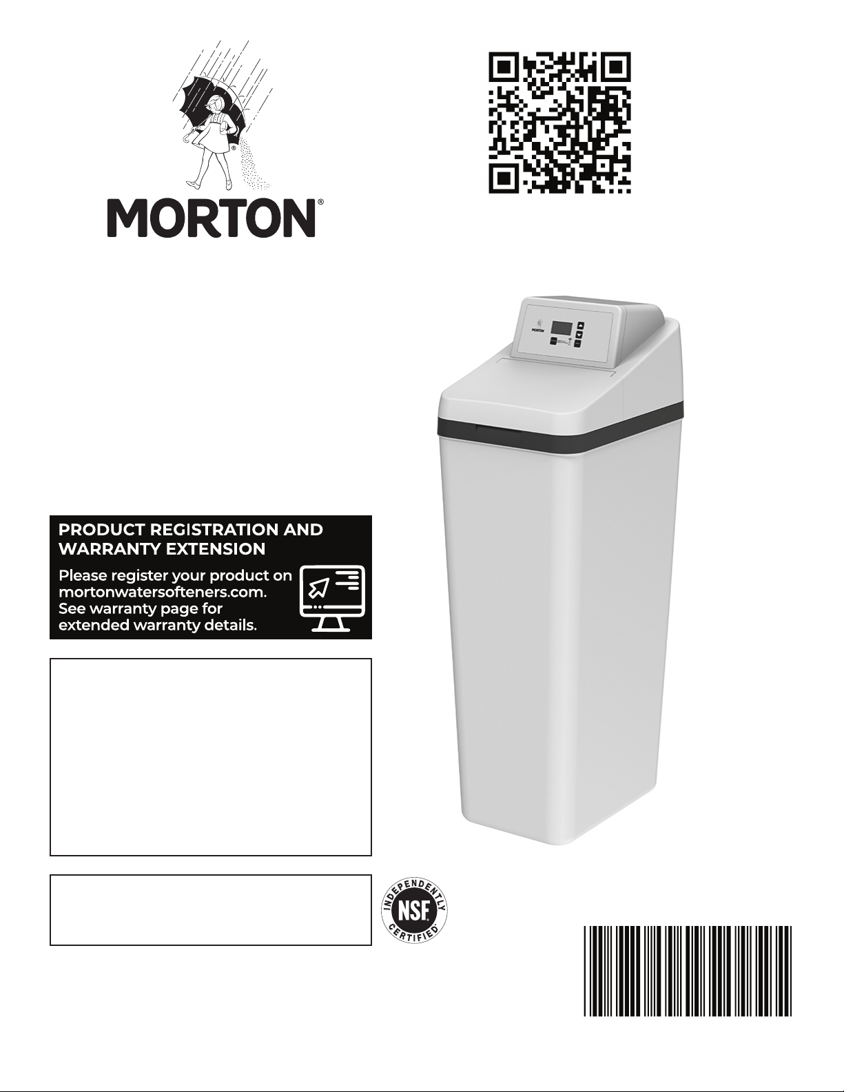
For best results use Morton
®
Clean
and Protect
®
or Morton
®
Clean
and Protect
®
Plus Rust Defense
®
Pellets in your water softener.
Manufactured and warranted by
Water Channel Partners
1890 Woodlane Drive
Woodbury, MN 55125
If you have any questions or concerns when
installing, operating or maintaining your
water softener, call our toll free number:
1-888-64 WATER
(1-888-649-2837)
or visit www.mortonwatersofteners.com
When you call, please be prepared to provide
the model and serial number of your product,
found on the rating decal, located on the rim
below the salt lid hinges.
7394727 (Rev. A 1/19/23)
To obtain a full manual,
scan this QR code or visit:
www.mortonwatersofteners.com
2 Morton
®
Water Softener Installation & Operation Manual
Protect your new water softener with
Morton
®
Clean and Protect
®
or Morton
®
Clean and Protect
®
Plus Rust Defense
®
Pellets
Morton
®
Water Softener Salt Pellets are made with a time-release
formula that works with your softener to help prevent mineral buildup
and keep your home’s pipes and appliances working at their best.
Whether you’re looking to remove iron and fight buildup, or extend your
water softener’s life, Morton
®
has the right salt for you. Use one or both
of our premium formula pellets in any water softener for the best results.
Remember to fill your water softener with Morton
®
America’s #1 Brand of Water Softener Salt!
Morton
®
Water Softener Installation & Operation Manual 3
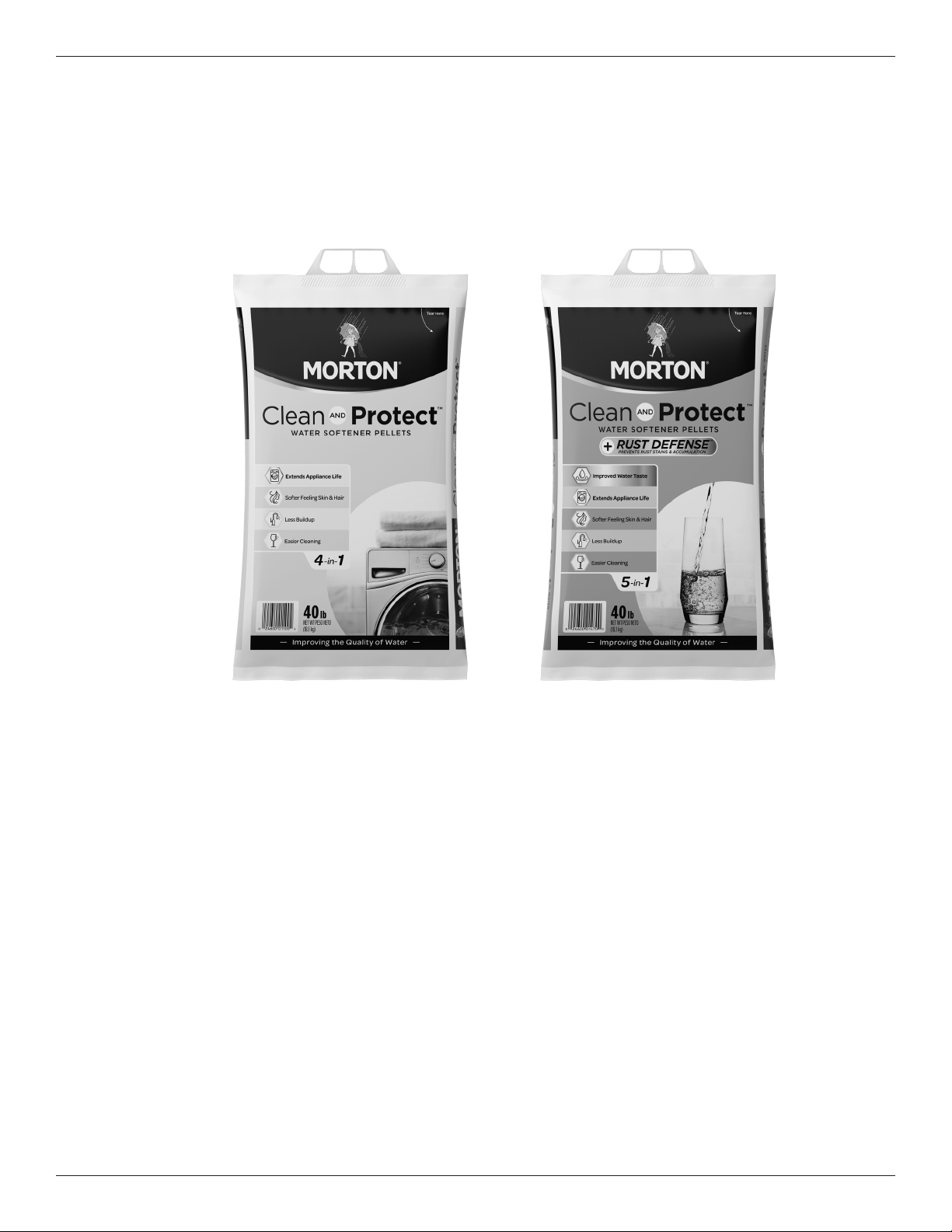
Before You Start
Packing List
48"
SIDE VIEW FRONT VIEW
TOP VIEW
20-1/2"
15"
41-3/4"
IN - OUT
3-3/4"
IN
OUT
OUT
IN
IN – OUT
FIG. 1
FRONT VIEW
SIDE VIEW
TOP VIEW
20-1/2”
(52 cm)
41-3/4”
(106 cm)
48”
(122 cm)
3-3/4” (9.5 cm)
15”
(38 cm)
NOTE: Due to variances in
production and assembly,
the water softener valve
height may vary by up to
1/2”, and may not match
previously installed sys-
tems. This will not affect
system performance.
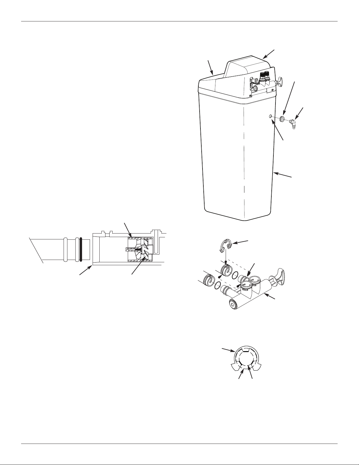
Dimensions
Drain Hose
Bypass Valve
Grommet
Installation
Adaptors
Silicone Grease
O-rings
Clips
(2 are shipped
installed on the
softener’s valve)
Adaptor ElbowHose Clamps
= The water softener requires a minimum water flow of 3 gallons per minute at the inlet. Maximum allowable inlet
water pressure is 125 psi. If daytime pressure is over 80 psi, nighttime pressure may exceed the maximum. Use
a pressure reducing valve if necessary (Adding a pressure reducing valve may reduce the flow). Failure to use a
pressure reducing valve may cause damage to the system, resulting in flooding and damage to property. If your
home is equipped with a back flow preventer, an expansion tank must be installed in accordance with local codes
and laws.
= The water softener works on 24V DC electrical power, supplied by a direct plug-in power supply (included). Be
sure to use the included power supply and plug it into a nominal 120V, 60 Hz household outlet that is in a dry
location only, grounded and properly protected by an overcurrent device such as a circuit breaker or fuse.
= Do not use this system to treat water that is microbiologically unsafe or of unknown quality without adequate dis-
infection upstream or downstream of the system.
European Directive 2002/96/EC requires all electrical and electronic equipment to be disposed of according
to Waste Electrical and Electronic Equipment (WEEE) requirements. This directive or similar laws are in
place nationally and can vary from region to region. Please refer to your state and local laws for proper dis-
posal of this equipment.
4 Morton
®
Water Softener Installation & Operation Manual
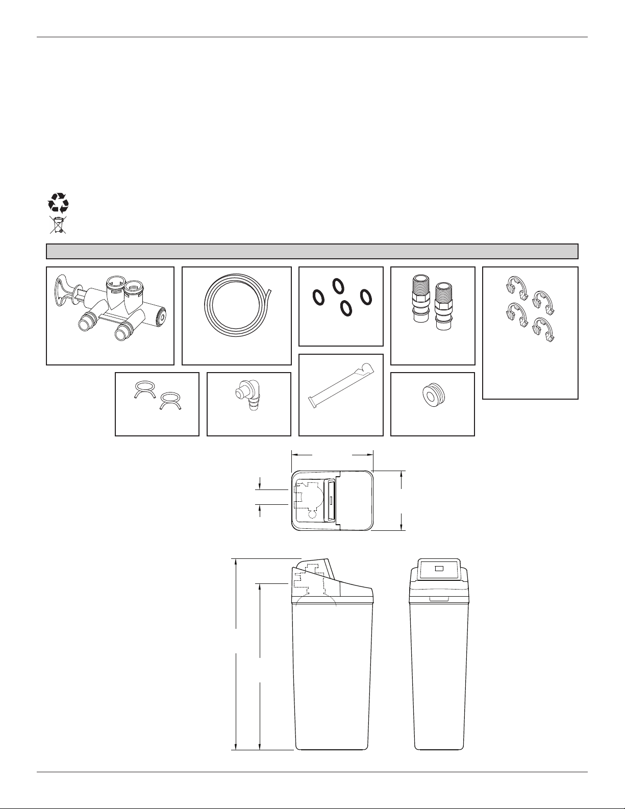
Installation Requirements
Plumbing Codes
All plumbing must be completed in accordance with
national, state and local plumbing codes.
Laundry TubStandpipe
1-1/2”
air gap
Floor Drain
In the state of Massachusetts: The Commonwealth
of Massachusetts plumbing code 248-CMR shall
be adhered to. A licensed plumber shall be used
for this installation.
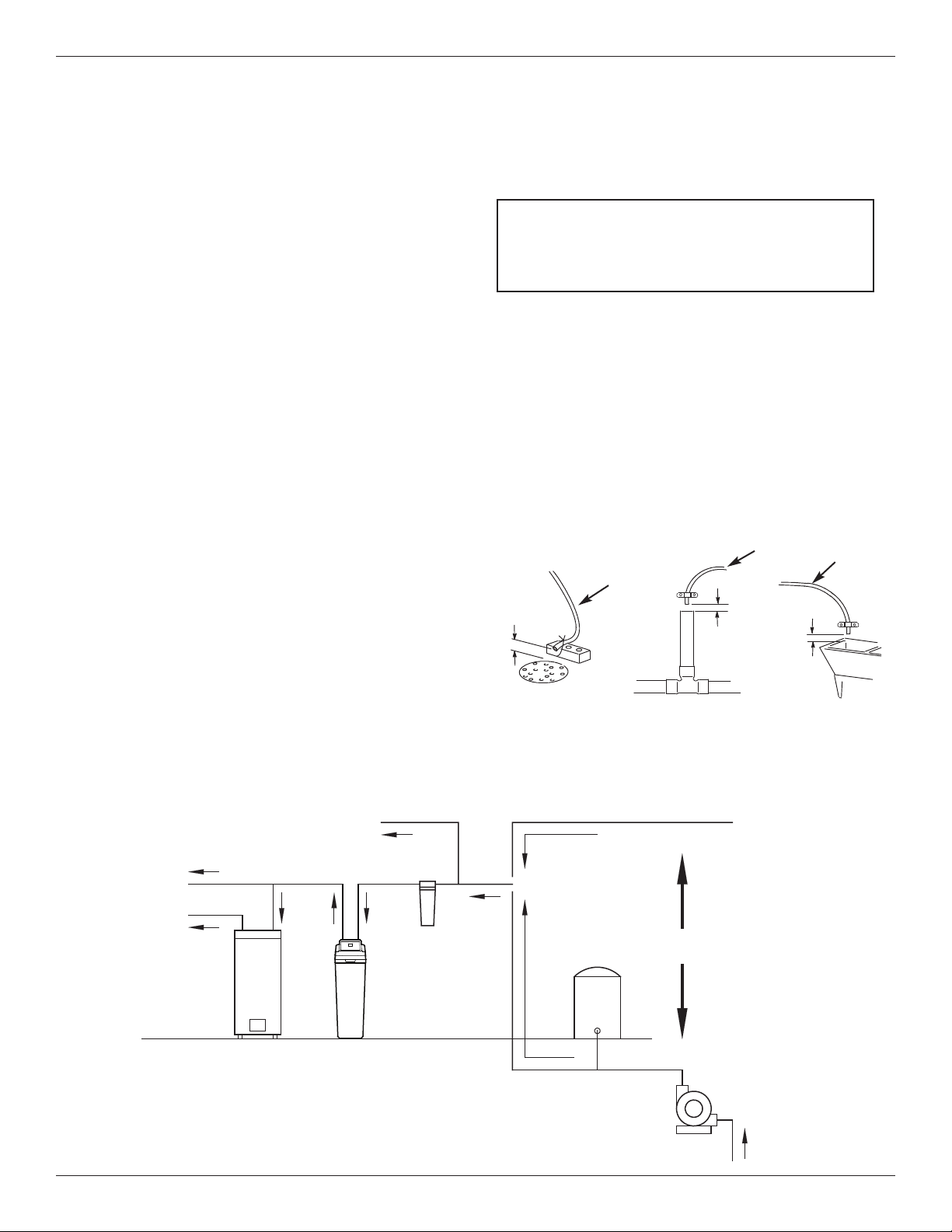
Air Gap Requirements
A drain is needed for the water discharged from the
valve during the softener’s regeneration cycle (See
Figure 2). A floor drain, close to the water softener, is
preferred. A laundry tub, standpipe, etc. are other
drain options. Secure valve drain hose in place.
Leave an air gap of 1-1/2” between the end of the
hose and the drain. This gap is needed to prevent
backflow of sewer water into the water softener. Do
not put the end of the drain hose into the drain.
FIG. 2
1-1/2”
air gap
Drain
Hose
Drain
Hose
1-1/2”
air gap
Location Requirements
Consider all of the following when selecting an installa-
tion location for the water softener.
= Do not locate the water softener where freezing
temperatures occur. Do not attempt to treat water
over 120ºF. Freezing temperatures or hot water
damage voids the warranty.
= To condition all water in the home, install the water
softener close to the water supply inlet, and
upstream of all other plumbing connections, except
outside water pipes. Outside faucets should remain
on hard water to avoid wasting conditioned water
and salt.
= A nearby drain is needed to carry away regenera-
tion discharge (drain) water. Use a floor drain,
laundry tub, sump, standpipe, or other options
(check your local codes). See "Air Gap
Requirements" and "Valve Drain Requirements"
sections.
= The water softener works on 24V DC electrical
power, supplied by a direct plug-in power supply
(included). Provide nearby a 120V, 60Hz electrical
outlet in accordance with NEC and local codes.
= Always install the water softener between the water
inlet and water heater. Any other installed water
conditioning equipment should be installed between
the water inlet and water softener (See Figure 3
below).
= Avoid installing in direct sunlight. Excessive sun
heat may cause distortion or other damage to non-
metallic parts.
The Proper Order To Install Water Treatment Equipment
FIG. 3
Pressure
Tank
City Water Supply
Well Water Supply
Well
Pump
OR
Optional
Sediment
Filter
Water
Heater
Water
Softener
Untreated Water to
Outside Faucets
Hot Water
to House
Cold Water
to House
Drain
Hose
Morton
®
Water Softener Installation & Operation Manual 5
Installation Requirements
Valve Drain Requirements
Using the flexible drain hose (included), measure and
cut to the length needed. Flexible drain hose is not
allowed in all localities (check your plumbing codes). If
local codes do not allow use of a flexible drain hose, a
rigid valve drain run must be used. Purchase a com-
pression fitting (1/4 NPT x 1/2 in. minimum tube) and
1/2" tubing from your local hardware store. Plumb a
rigid drain as needed (See Figure 5).
NOTE: Avoid drain hose runs longer than 30 feet.
Avoid elevating the hose more than 8 feet
above the floor. Make the valve drain line as
short and direct as possible.
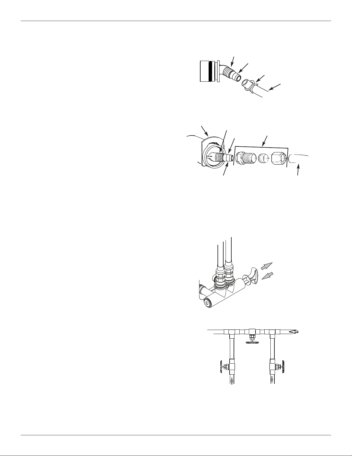
Inlet / Outlet Plumbing Options
Always install either a single bypass valve (provided),
as shown in Figure 6, or, if desired, parts for a 3 valve
bypass system (not included) can be purchased and
assembled, as shown in Figure 7. Bypass valves
allow you to turn off water to the softener for mainte-
nance if needed, but still have water in house pipes.
Pipe fittings must be 3/4” minimum.
Use:
= Copper pipe
= Threaded pipe
= PEX (Crosslinked Polyethylene) pipe
= CPVC plastic pipe
= Other pipe approved for use with potable water
IMPORTANT: Do not solder with plumbing attached to
installation adaptors and single bypass
valve. Soldering heat will damage the
adaptors and valve.
FIG. 7
Single Bypass Valve
3 Valve Bypass
From Water
Softener
To Water
Softener
Inlet
Valve
Outlet
Valve
Bypass
Valve
FIG. 6
Pull out for “Service”
(Soft water)
Push in for
“Bypass”
FIG. 4
FIG. 5
1/4” NPT
Thread
Clip
Barbs
1/4 NPT
Threads
1/2” Outside Dia.
Copper Tube
(not included)
Compression Fitting.
1/4 NPT x 1/2” O.D.
Tube (not included)
Cut barbs from drain fit-
ting (pull clip to remove
fitting from valve)
Barbs for 3/8”
I.D. Tubing
Drain Hose
Hose Clamp
6 Morton
®
Water Softener Installation & Operation Manual
Installation Instructions
Step 1. Turn Off Water Supply
1. Close the main water supply valve, located near the
well pump or water meter.
2. Shut off the electric or fuel supply to the water
heater.
3. Open all faucets to drain all water from house pipes.
NOTE: Be sure not to drain water from the water
heater, as damage to the water heater ele-
ments could result.
Step 2. Assembly
1. Morton
®
water softener models are factory assem-
bled. During installation, unsnap and remove the
top cover, together with the salt lid (See Figure 10),
to expose the softener valve assembly. Set them
aside to prevent damage.
2. Install the brine tank overflow grommet and elbow
into the 13/16” diameter hole in the back of the salt
storage tank wall (See Figure 10).
Step 3. Move the Unit into Place
1. Move the water softener into the desired location.
Set it on a solid, level surface.
IMPORTANT: Do not place shims directly under the
salt storage tank to level the softener.
The weight of the tank, when full of
water and salt, may cause the tank to
fracture at the shim.
2. Visually check and remove any debris from the
water softener valve inlet and outlet ports.
3. Make sure the turbine assembly spins freely in the
"out" port of the valve (See Figure 9).
4. If not already done, put a light coating of silicone
grease on the single bypass valve o-rings.
5. Push the single bypass valve into the softener valve
as far as it will go. Snap the two large holding clips
into place, from the top down as shown in Figures
11 & 12.
IMPORTANT: Be sure the clips snap firmly into place
so the single bypass valve will not pull
out.
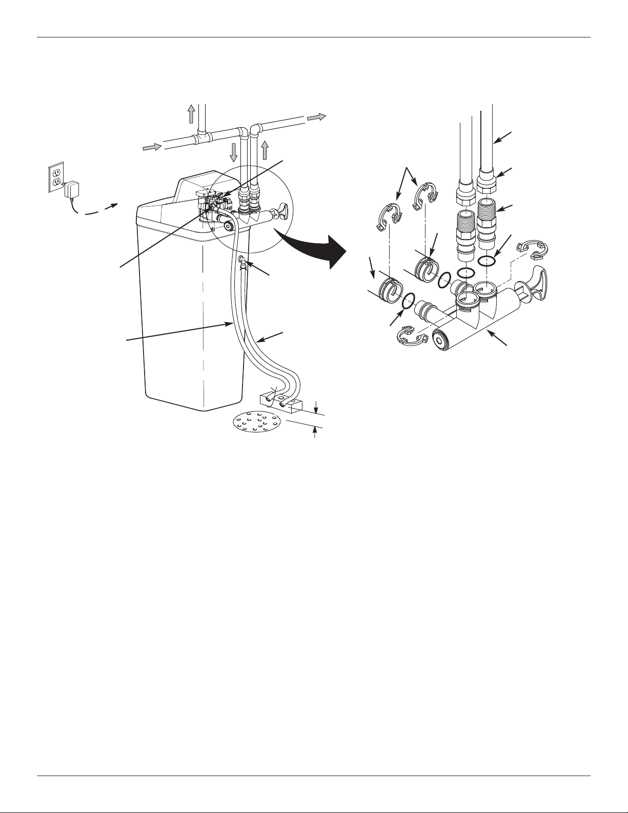
TYPICAL INSTALLATION
FIG. 8A
NOTE: See “Air Gap Requirements” section.
To Outside
Faucets
Soft
Water
Main Water Pipe
Water
Softener
Valve
Valve Drain
Elbow
Valve Drain
Hose*
Floor Drain
Overflow
Drain Elbow
Salt Storage
Tank Overflow
Hose*
Secure Valve Drain Hose
in place over Floor Drain
1-1/2”
air gap
Plug-in
Power
Supply
To
Controller
Hard
Water
*Do not connect the
water softener valve
drain hose to the salt
storage tank overflow
hose.
Inlet
Outlet
Pipe
1” NPT Sweat
Adaptor (not
included)
O-ring
Single
Bypass Valve
1” NPT
Threaded
Adaptor
O-ring
Clips
Morton
®
Water Softener Installation & Operation Manual 7
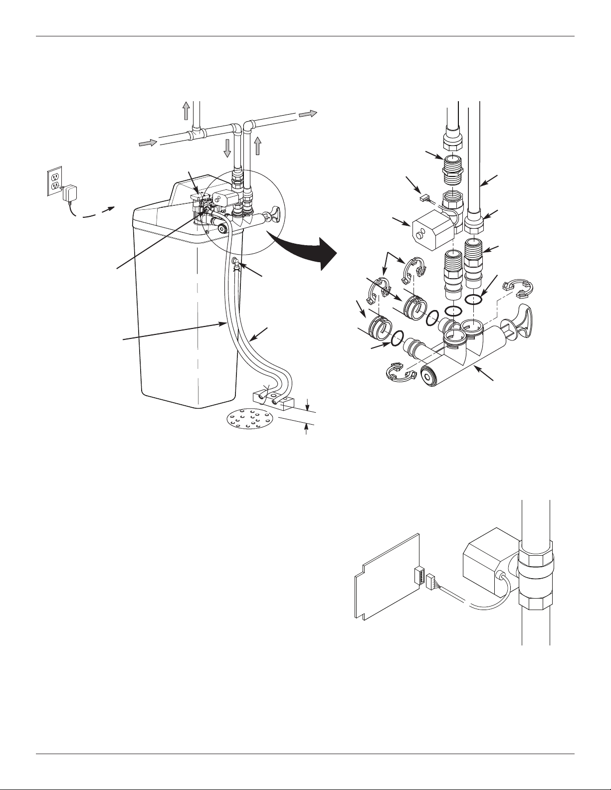
TYPICAL INSTALLATION (with optional motorized water shutoff valve)
Installation Instructions
Optional Motorized
Water Shutoff Valve
Electronic Control
Board on back of
Faceplate
Plug cable into elec-
tronic control board
(power must be off)
FIG. 8C
Step 4. (Optional) Install the Motorized Water Shutoff Valve
If you purchased the optional water shutoff valve,
install it in the plumbing upstream of the softener inlet.
Figure 8B shows installation with the shutoff valve
immediately upstream of the bypass valve inlet, using
one of the softener’s installation adaptors and the 1”
NPT nipple provided with the shutoff valve.
The shutoff valve may also be installed in the plumbing
farther upstream of the softener, making sure that the
10 foot long cable will reach the softener’s electronic
control board (See Figure 8C). The shutoff valve’s
inlet and outlet are female 1” NPT. Support the weight
of the shutoff valve.
After completing plumbing, make sure that the water
softener is not powered up, and plug the cable from
the shutoff valve into the corresponding connector on
the electronic control board (See Fig. 8C).
CAUTION: Do not place fingers into the motorized
shutoff valve when it is plugged into the electronic con-
troller.
NOTE: The shutoff valve may be operated manually
by pulling out and turning the knob on the shutoff valve
body, although there is no need to do this when
installing.
FIG. 8B
NOTE: See “Air Gap Requirements” section.
To Outside
Faucets
Soft
Water
Main Water Pipe
Water
Softener Valve
Valve Drain
Elbow
Valve Drain
Hose*
Floor Drain
Overflow
Drain Elbow
Salt Storage
Tank Overflow
Hose*
1-1/2”
air gap
Plug-in
Power
Supply
To
Controller
Hard
Water
*Do not connect the
water softener valve
drain hose to the salt
storage tank overflow
hose.
Inlet
Outlet
Pipe
1” NPT Sweat
Adaptor (not
included)
O-ring
Single
Bypass Valve
1” NPT
Threaded
Adaptor
O-ring
Secure Valve Drain
Hose in place over
Floor Drain
Optional Motorized
Water Shutoff Valve
(not included with
water softener)
1” NPT Nipple
(provided with
optional motorized
water shutoff valve)
Plug into Controller
Clips
Installation Instructions
FIG. 12
Correct Assembly
Clip
Outside diameter
of clip channel on
single bypass valve
Outside diameter
of water softener
valve inlet & outlet
NOTE: Be sure all 3 tabs of the clip go through the matching
holes on the water softener valve inlet or outlet, and
fully into the channel on the single bypass valve.
Make sure that the tabs are fully seated.
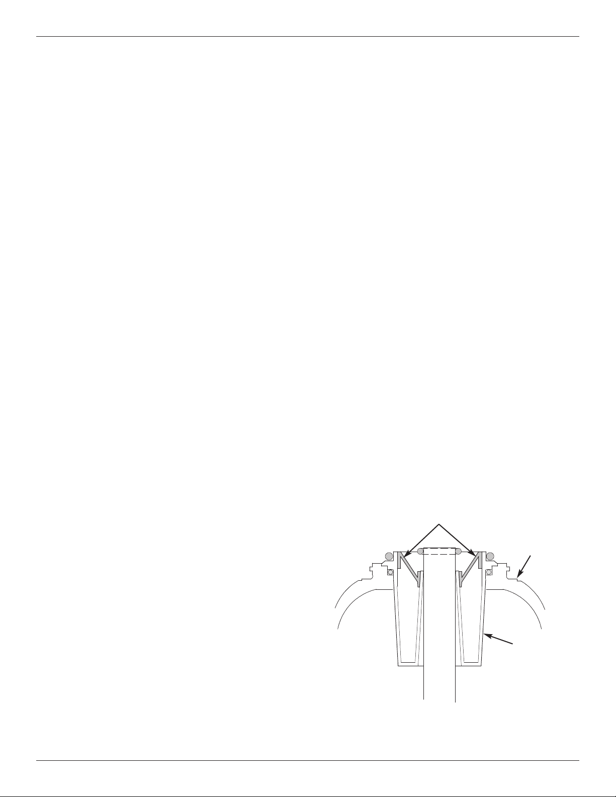
Step 5. Complete Inlet and Outlet
Plumbing
Measure, cut, and loosely assemble pipe and fittings
from the main water pipe to the inlet and outlet ports of
the water softener valve. Be sure to keep fittings fully
together, and pipes squared and straight.
Be sure hard water supply pipe goes to the water sof-
tener valve inlet side.
NOTE: Inlet and outlet are marked on the water sof-
tener valve. Trace the water flow direction to
be sure hard water is to inlet.
IMPORTANT: Be sure to fit, align and support all
plumbing to prevent putting stress on
the water softener valve inlet and outlet.
Undue stress from misaligned or unsup-
ported plumbing may cause damage to
the system.
Complete the inlet and outlet plumbing for the type of
pipes you will be using.
FIG. 9
Turbine
Support
Valve Outlet Turbine
FIG. 11
Clip
Channel
Single Bypass Valve
8 Morton
®
Water Softener Installation & Operation Manual
FIG. 10
Top Cover
Brine Tank
Overflow
Elbow
Brine Tank
Overflow
Grommet
13/16” Hole
Salt Lid
Salt
Storage
Tank

Morton
®
Water Softener Installation & Operation Manual 9
Installation Instructions
Step 6. Cold Water Pipe Grounding
CAUTION: The house cold water pipe (metal only)
is often used as a ground for the house
electrical system, The 3-valve bypass
type of installation, shown in Figure 7,
will maintain ground continuity. If you
use a plastic bypass valve at the unit,
continuity is broken. To restore the
ground, do the following:
1. Install a #4 copper wire across the removed section
of main water pipe, securely clamping it at both
ends (See Figure 13) - parts not included.
NOTE: Check local plumbing and electrical codes
for proper installation of the ground wire.
The installation must conform to them. In
Massachusetts, plumbing codes of
Massachusetts shall be conformed to.
Consult with your licensed plumber.
FIG. 13
Ground
Wire
Clamp (2)
Step 8. Install Salt Storage Tank
Over flow Hose
1. Measure, cut to needed length and connect the 3/8"
drain line (provided) to the salt storage tank over-
flow elbow and secure in place with a hose clamp.
2 Run the hose to the floor drain, or other suitable
drain point no higher than the drain fitting on the salt
storage tank (This is a gravity drain). If the tank
overfills with water, the excess water flows to the
drain point. Cut the drain line to the desired length
and route it neatly out of the way.
IMPORTANT: For proper operation of the water soften-
er, do not connect the water softener
valve drain hose from Step 7 to the salt
storage tank overflow hose.
Step 9. Pressure Testing for Leaks
To prevent air pressure in the water softener and
plumbing system, do the following steps exactly in
order:
1. Fully open two or more softened cold water faucets
nearby the water softener, located downstream from
the water softener.
2. Place the single bypass valve or 3 valve bypass in
"bypass" position. See Figures 6 & 7.
3. Fully open the main water supply valve. Run water
until there is a steady flow from the opened faucets,
with no air bubbles.
4. Place bypass valve(s) in "service" or soft water posi-
tion exactly as follows:
= Single bypass valve: Slowly move the valve stem
toward "service," pausing several times to allow
the water softener to fill with water.
= 3 valve bypass: Fully close the bypass valve and
open the outlet valve. Slowly open the inlet
valve, pausing several times to allow the water
softener to fill with water.
5. After about three minutes, open a hot water faucet
until there is a steady flow and there are no air bub-
bles, then close this faucet.
6. Close all cold water faucets and check for leaks at
the plumbing connections that you made.
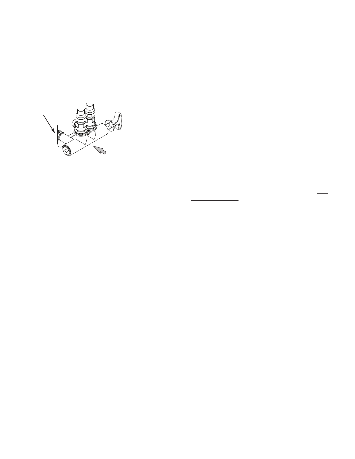
7. Check for leaks around clips at softener’s inlet and
outlet. If a leak occurs at a clip, depressurize the
plumbing (turn off the water supply and open
faucets) before removing clip. When removing clips
at the softener’s inlet or outlet, push the single
Step 7. Install Valve Drain Hose
NOTE: See valve drain options on pages 3 & 4.
1. Measure, cut to needed length and connect the 3/8"
drain line (provided) to the water softener valve
drain fitting. Use a hose clamp to hold the hose in
place.
IMPORTANT: If codes require a rigid drain line see
“Valve Drain requirements" section.
2. Run the drain hose (or a rigid line) to the floor drain.
Secure drain hose. This will prevent “whipping'' dur-
ing regenerations. Be sure to provide a 1-1/2”
minimum air gap to prevent possible sewer
water backup. See “Air Gap Requirements" sec-
tion.
NOTE: In addition to a floor drain, you can use a laun-
dry tub or standpipe as a good drain point for
this hose.. Avoid long drain hose runs, or ele-
vating the hose more than 8’ above the floor.
continued on next page
10 Morton
®
Water Softener Installation & Operation Manual
Installation Instructions
bypass valve body toward the softener (See Figure
14). Improper removal may damage clips. Do not
reinstall damaged clips.
continued from previous page
Questions? Call Toll Free 1-888-64 WATER (1-888-649-2837)
or visit
www.mortonwatersofteners.com
When you call, please be prepared to provide the model and serial number,
found on the rating decal, located on the rim below the salt lid hinges.
Step 10. Add Water and Salt to the
Salt Storage Tank
1. Using a container, add about three gallons of clean
water into the salt storage tank.
2. Add Morton
®
Clean and Protect
™
or Clean and
Protect
™
Plus Rust Defense
™
Pellets to the storage
tank.
NOTE: See Page 17 for additional information on
salt.
Step 11. Plug in the Power Supply
During installation, the water softener wiring may be
moved or jostled from place. Check to be sure all
leadwire connectors are secure on the back of the
electronic board and be sure all wiring is away from
the valve gear and motor area, which rotates during
regenerations.
1. Plug the water softener’s power supply into an elec-
trical outlet that is not controlled by a switch and is
approved by local codes.
Step 12. Program the Controller
1. Install the softener’s top cover and salt lid.
2. Complete the programming steps on pages 11-13.
Step 13. Sanitizing the Softener
Care is taken at the factory to keep your unit clean and
sanitary. Materials used to make the unit will not infect
or contaminate your water supply, and will not cause
bacteria to form or grow. However, during shipping,
storage, installation and operation, bacteria could get
into the unit. For this reason, sanitizing as follows is
suggested* when installing.
1. Open the salt lid and pour about 3 oz. (6 table-
spoons) of household bleach into the softener
brinewell.
2 Make sure the bypass valve(s) is in the “service”
(open) position.
3 Start a recharge: Press the RECHARGE button and
hold for 3 seconds, until “RECHARGE NOW” begins
to flash in the display. This recharge draws the sani-
tizing bleach into and through the water softener.
Any air remaining in the unit is purged to the drain.
4 After the recharge has completed, fully open a cold
water faucet, downstream from the softener, and
allow 50 gallons of water to pass through the sys-
tem. This should take at least 20 minutes. Close
the faucet.
*
Recommended by the Water Quality Association. On some
water supplies, the unit may need periodic disinfecting.
Step 14. Restart the Water Heater
Turn on the electricity or fuel supply to the water
heater and relight the pilot, if applicable.
NOTE: The water heater is filled with hard water and,
as hot water is used, it refills with conditioned
water. In a few days, the hot water will be fully
conditioned. To have fully conditioned hot
water immediately, wait until the initial recharge
(Step 13) is over. Then, drain the water heater
(following instructions for water heater) until
water runs cold.
FIG. 14
...depressurize the
plumbing, then push
Bypass Valve body
toward softener
If removing
clips...
Morton
®
Water Softener Installation & Operation Manual 11
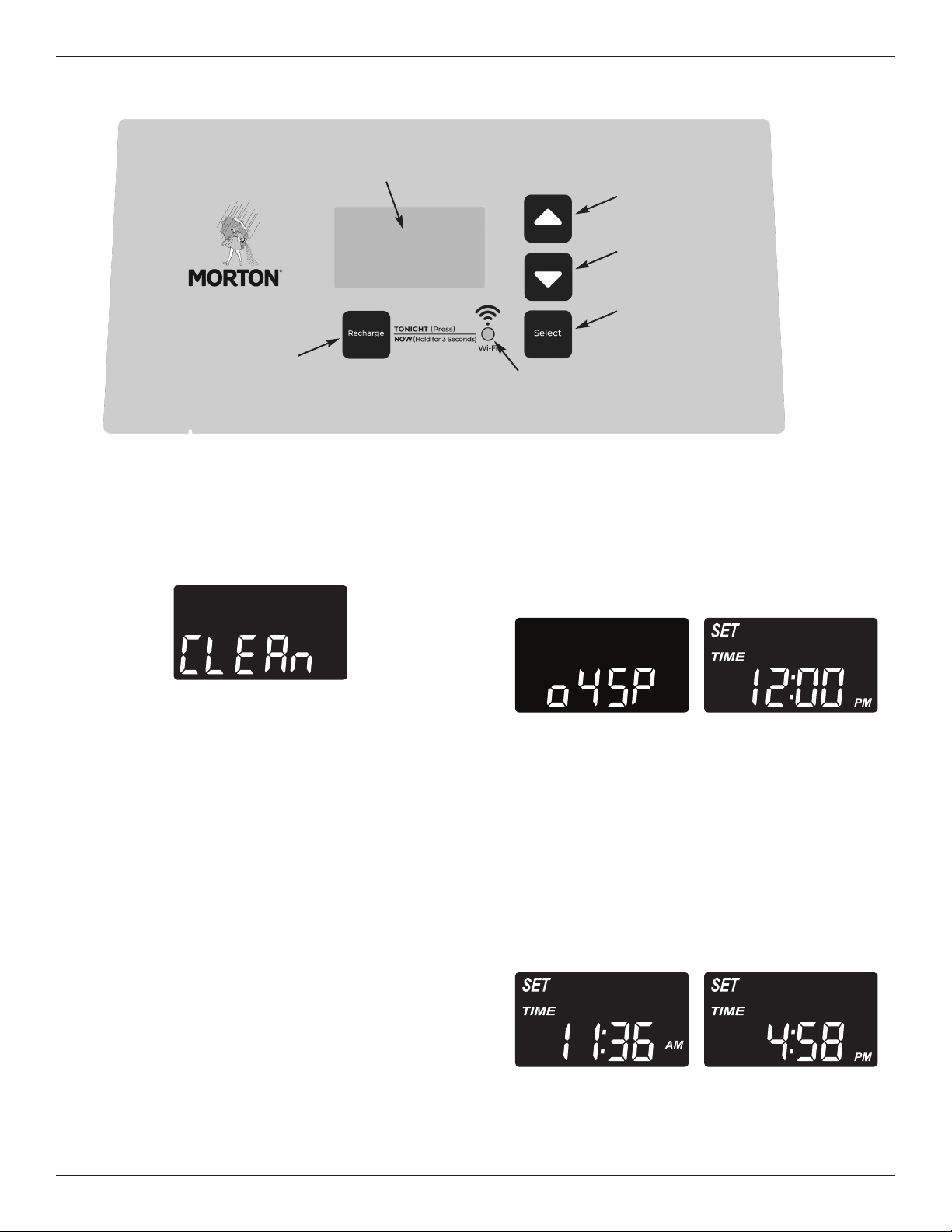
FIG. 16
Clean Reminder
The screen in Figure 16 appears, with “CLEAn” flash-
ing in the display, when four months have elapsed on
the system’s timer since start up or the last reset.
This is a reminder to use Morton
®
MWSC Water
Softener Cleanser three times a year. To reset the
timer, press any button on the control panel and
“CLEAn” will disappear.
Program the Softener
When the power supply is plugged into the electrical
outlet, the model code (o45P) and a software version
number (example: r4.4), are briefly shown in the face-
plate display. Then the words “SET TIME” appear
and “12:00 PM” begins to flash.
NOTE: If “- - - -” shows in the display, press the
r UP or s DOWN button until the model
code shows in the display. Then, press the
SELECT button to set, and change to the
flashing “SET TIME" display.
Step 1. Set Time of Day
If the words “SET TIME" do not show in the display,
press the SELECT button several times until they do.
Programming the Water Softener
FIG. 17
FIG. 18
continued on next page
FIG. 15
RECHARGE
button
CONNECTION
STATUS light
UP button
DOWN
button
SELECT
button
Display
12 Morton
®
Water Softener Installation & Operation Manual
Programming the Water Softener
FIG. 19
continued from previous page
1. Press the
r UP or s DOWN buttons to set the
present time. Up moves the display ahead; down
sets the time back. Be sure AM or PM is correct.
NOTE: Press buttons and quickly release to slowly
advance the display. Hold the buttons down
for fast advance.
NOTE: On Wi-Fi connected systems, the current time
will be updated and maintained automatically
via Wi-Fi.
2. When the correct time is displayed, press the
SELECT button, and the display will change to
show the “Hardness” screen.
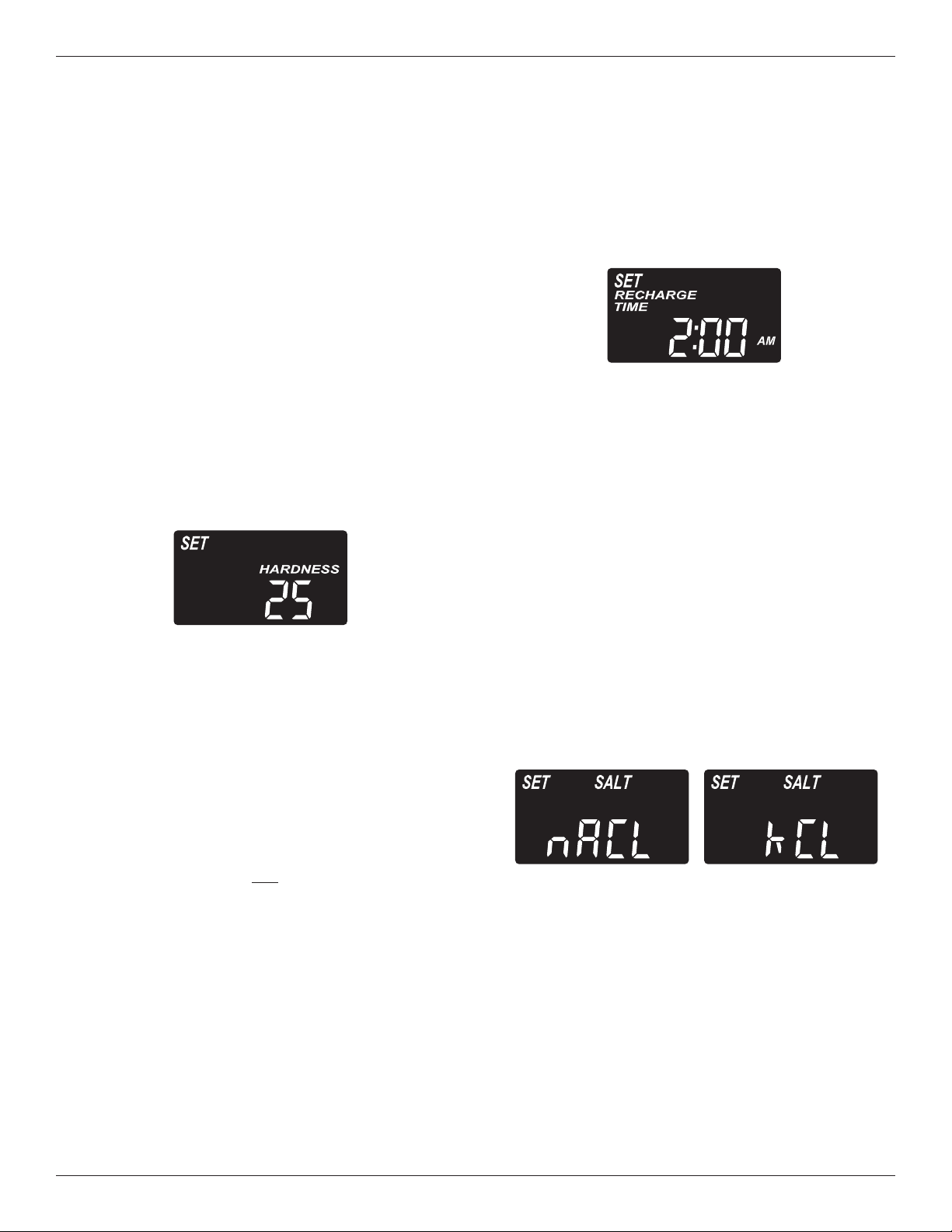
Step 2. Set Water Hardness Number
If you completed the previous step, the words “SET
HARDNESS" should show in the display. Otherwise,
press the SELECT button several times until they do.
FIG. 20
1. The softener’s default recharge start time is 2:00
AM. This is normally a time of day when water is
not being used in the household. Hard water
bypasses the softener if the household draws
water during the recharge cycle. If a different
recharge start time is desired, press the
r UP or
s DOWN buttons to change the time, in 1-hour
increments. Be sure AM or PM is correct.
2. When the desired recharge start time is displayed,
press the SELECT button, and the display will
change to show one of the “Salt Type” screens
shown below.
Step 4. Set Salt Type
If you completed the previous step, either “nACL” (for
Sodium Chloride) or “kCL” (for Potassium Chloride)
should show in the display. Otherwise, press the
SELECT button several times until one of them does.
1. Press the
r UP or s DOWN buttons to set the
type of salt you will be using in your water softener.
The default is NaCl (standard Sodium Chloride
water softener salt). If you will be using KCl
(Potassium Chloride) instead, be sure to set salt
type to KCl. This setting adjusts the regeneration
cycle times to compensate for the different rate at
which KCl dissolves. See also Page 17 for more
information on salt types.
2. When the correct salt type is displayed, press the
SELECT button, and the display will change to
show the “Set Salt Level” screen.
FIG. 21
1. Press the r UP or s DOWN buttons to set the
hardness of your water supply, in grains per gallon.
The default is 25.
NOTE: If your water supply contains iron, compen-
sate for it by adding to the water hardness
number. For example, assume your water is
20 gpg hard and contains 2 ppm iron. Add 5
to the hardness number for each 1 ppm of
iron. In this example, you would use 30 for
your hardness number.
20 gpg hardness
2 ppm iron x 5 = 10 +10
(times) 30 HARDNESS NUMBER
2. When finished setting your water’s hardness num-
ber, press the SELECT button, and the display will
change to show the “Recharge Time” screen.
Step 3. Set Recharge (Regeneration)
Start Time
If you completed the previous step, the words
“SET RE CHARGE TIME" should show in the display.
Otherwise, press the SELECT button several times
until they do.
Morton
®
Water Softener Installation & Operation Manual 13
The softener enters the fill cycle of regeneration
immediately. This regeneration will take about 2 hours
to complete. Then, you will have soft water again.
NOTE: If the “Clean Feature” is set ON, the normal
regeneration cycle is preceded by a cleaning
backwash and rinse.
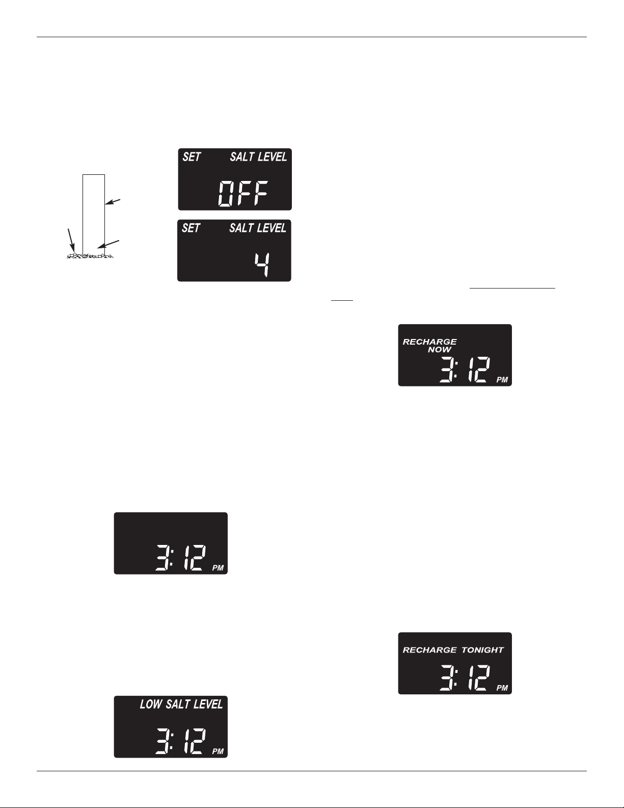
Recharge Tonight
If you do not want to start an immediate recharge, but
would like an extra recharge at the next preset
recharge start time, do the following to schedule a
recharge:
Press and release (do not hold) the RECHARGE but-
ton. “RECHARGE TONIGHT” will begin flashing in
the display, and the softener will begin regeneration
at the next preset recharge time (2:00 AM, or as set).
FIG. 25
FIG. 26
FIG. 24
FIG. 22
Programming the Water Softener
Step 5. Set Salt Level
If you completed the previous step, the words
“SET SALT LEVEL" should show in the display.
Otherwise, press the SELECT button until they do.
1. Lift the salt lid and level the salt in the storage
tank.
2. The salt level scale, on the brinewell inside the
tank, has numbers from 0 to 8 (see Fig. 22).
Observe the highest number the leveled salt is at,
or closest to.
3. Press the
r UP or s DOWN buttons until the
number on the screen corresponds to the salt level.
At level 2 or below, “LOW SALT LEVEL" will flash
in the display. If you wish to turn this feature off,
press the s DOWN button past 0, and the word
“OFF” flashes in the display.
4. When finished setting the salt level, press the
SELECT button. The display returns to the normal
time of day screen (Fig. 23).
Salt Level Monitor System
You must set salt level each time salt is added to
the water softener. The salt monitor system esti-
mates salt levels, and accuracy will vary with different
salts. At level 2 or below, “LOW SALT LEVEL" will
flash in the display (Fig. 24) to remind you to add salt.
Extra Recharge
Sometimes, a manually initiated recharge (regenera-
tion) may be desired, or needed. Two examples are:
= You have used more water than usual (guests visit-
ing) and you may run out of soft water before the
next automatic regeneration.
= You did not add salt to the softener before it ran
out. Add salt to the softener before regenerating.
You can start a regeneration immediately, or you can
set the controller to regenerate at the next preset
recharge time (2:00 AM, or as set).
Recharge Now
Press the RECHARGE button and hold for 3 sec-
onds, until the words “RECHARGE NOW” begin to
flash in the display.
FIG. 23
If you decide to cancel the regeneration before it
starts, press and release the RECHARGE button
once more. “RECHARGE TONIGHT” will stop flash-
ing in the display.
8
7
6
5
4
Brinewell
Numbers
Salt
Level
14 Morton
®
Water Softener Installation & Operation Manual
Questions? Call Toll Free 1-888-64 WATER (1-888-649-2837)
or visit www.mortonwatersofteners.com
When you call, please be prepared to provide the model and serial number,
found on the rating decal, located on the rim below the salt lid hinges.
California Efficiency Requirement
Your Morton
®
Water Softener has a “High
Efficiency” feature with an ON or OFF setting.
This softener setting is shipped in the OFF posi-
tion, which utilizes the maximum rated capacity
while most often achieving maximum salt effi-
ciencies. When installing this unit in the State of
California, you MUST turn this setting to the ON
position, which may initiate more frequent
recharges. However it will operate at 4000
grains per pound of salt or higher.
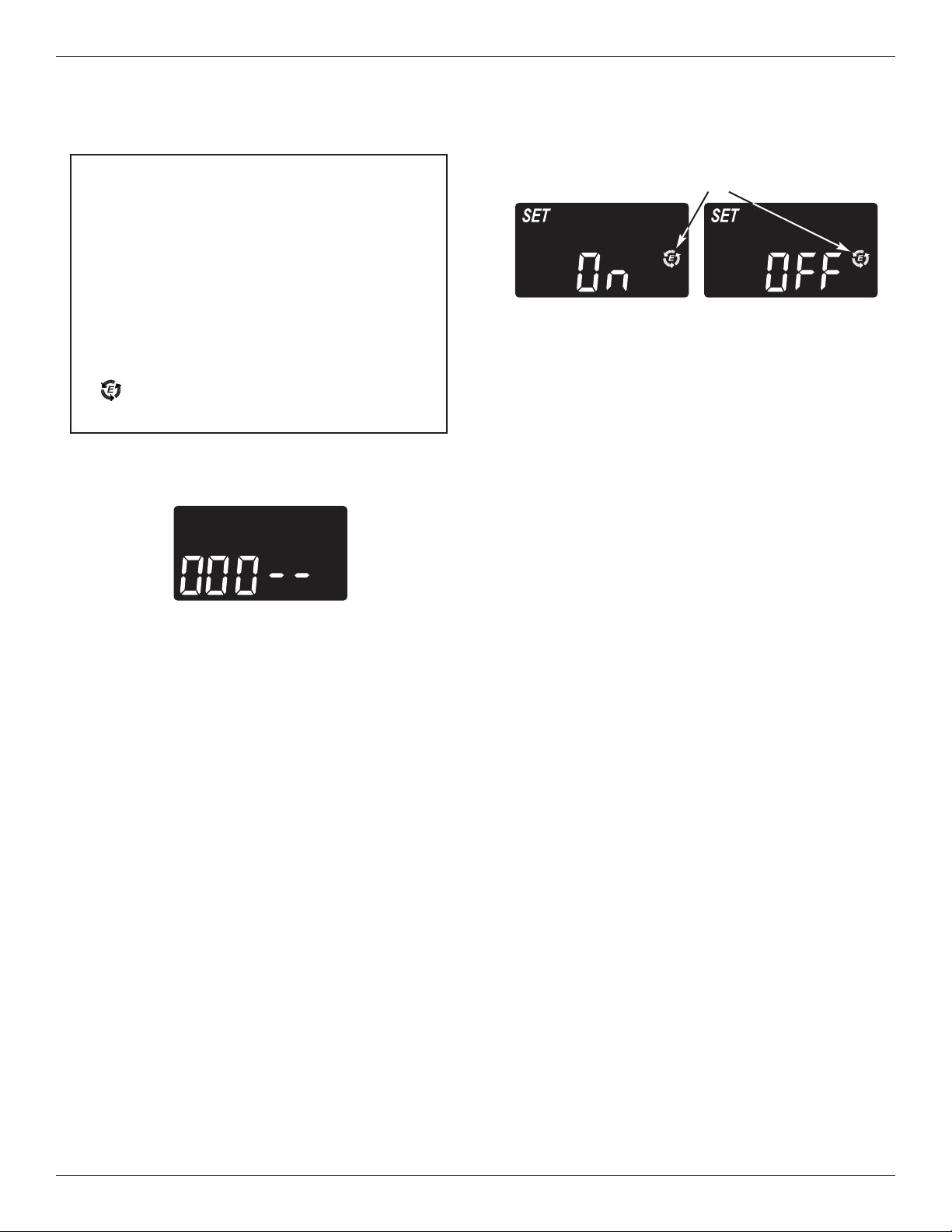
If you wish to turn the Salt Efficiency feature ON
( icon will show in the display), follow the
instructions on this page.
FIG. 27
FIG. 28
Efficiency Icon
1. Press and hold the SELECT button for 3 seconds
until “000 - -” shows in the display.
When the salt efficiency feature is ON, the water
softener will operate at salt efficiencies of 4000
grains of hardness per pound of salt or higher. The
softener may recharge more often using smaller
salt dosage and less water. This softener is
shipped with the efficiency feature set OFF.
3. Use the
r UP or s DOWN buttons to change
between OFF and ON. An efficiency icon will be
displayed when this feature is ON.
4. Press SELECT several times to return to the nor-
mal run (time of day) screen.
2. Then press (do not hold) SELECT again to display
one of the “Salt Efficiency” screens below.
Programming the Water Softener
Morton
®
Water Softener Installation & Operation Manual 15
Connecting the System to Wi-Fi
Step 1. Download the iQua™ App
Go to the App Store or Google Play and download
the iQua™ app. This must be installed on your
phone to set up an account and connect your water
softener to the “cloud”.
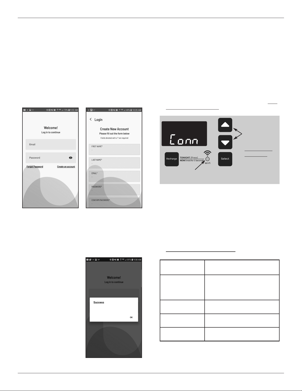
Step 2. Set Up Your Account
1. Activate the iQua™ app.
2. On the welcome screen, click Create an Account.
Step 3. Put Water Softener Control
into Connect Mode
1. If you haven’t already done so, program the water
softener with time, hardness, salt level, etc., as
shown on pages 11-13.
2. Make sure that the softener’s display shows the
current time, without the word “SET”. Press the
SELECT button several times if “SET” shows.
3. On the water softener’s front panel (see Fig. 32),
press both the
r UP and s DOWN buttons, and
hold them for 3 seconds.
3. Fill in the required fields with your information
(name, phone number, address, etc.). Enter the e-
mail address you want to receive notifications.
Create a password to access your account.
4. Agree to the terms and press Complete.
5. A message to check
your e-mail appears.
An activation e-mail
has been sent to the
address you provided
when creating the
account. If you don’t
see it your inbox,
check your spam or
junk folders, and flag it
as safe so that future
notifications from
myiqua.com will not be
blocked. Wait to click
the link in this e-mail
until you have put the
water softener control
into Connect Mode, as
follows.
4. Release the buttons when “Conn” appears in the
display (See Fig. 32) and the connection status
light begins flashing amber.
5. The system is now in Connect Mode, ready to be
connected to the “cloud”, and will remain for 15
minutes. If Connect Mode has “timed out” and the
light is off, you can enter Connect Mode again by
pressing both the
r UP and s DOWN buttons
and holding them for 3 seconds.
FIG. 30
Check your email to activate your
account
FIG. 31
Connection Status
light indication
Status
Flashing Amber
(for up to 15 min-
utes)
System is in Connect Mode,
waiting to be connected to the
“cloud” via the home’s wireless
router.
Green
System successfully connected
to the “cloud” and registered.
Red
System is currently receiving
an over-the-air update.
No light
System not currently connected
to the “cloud”.
6. With the system in the Connect Mode, follow the
instructions on the next page to use the app to
connect your water softener to the “cloud” via the
home’s wireless router.
FIG. 32
CONNECTION STATUS
light (see table below)
Press both
UP and
DOWN
buttons,
and hold for
3 seconds,
to put into
Connect Mode
FIG. 29
16 Morton
®
Water Softener Installation & Operation Manual
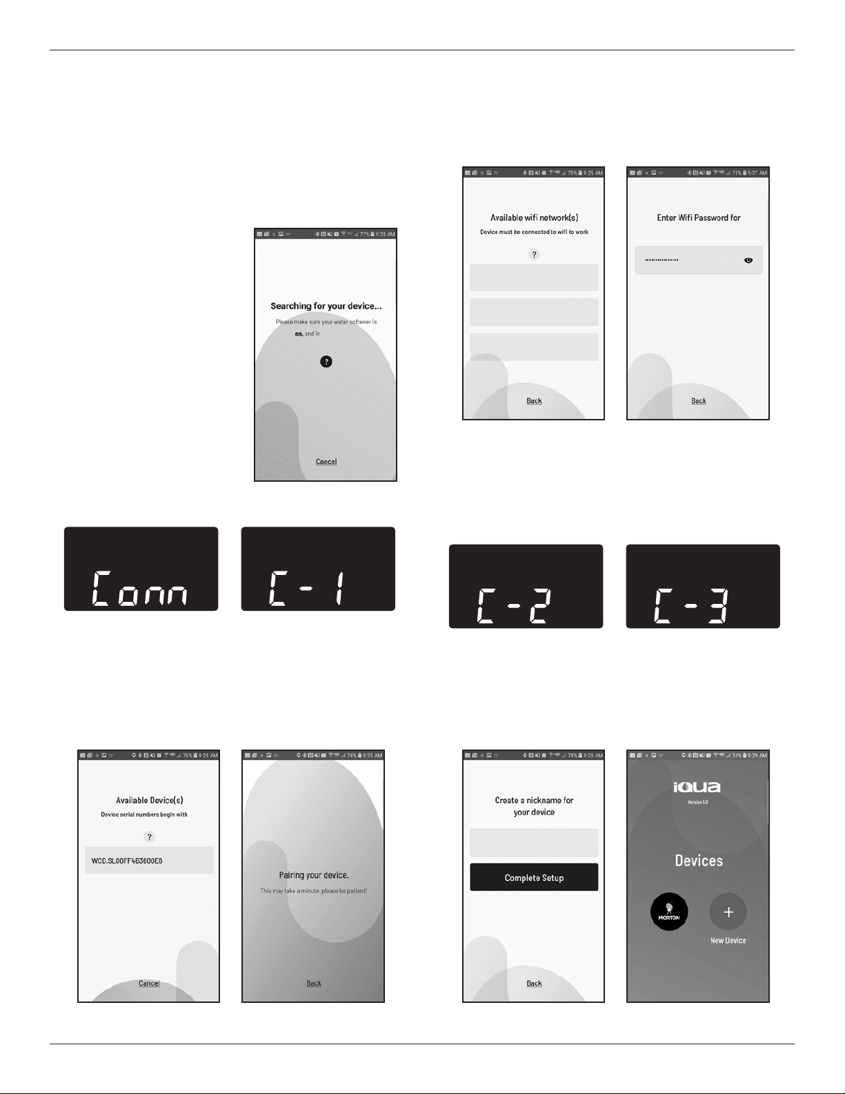
Step 4. Connect and Register Your
Water Softener
1. If you completed the steps on the previous page,
you will have received an account activation
e-mail from myiqua.com. Open this e-mail and
click on the Activate Account link.
2. Sign in to your account
using the e-mail address
and password you pro-
vided when setting it up.
3. The app screen will
change to show
Searching for your
device...
4. Verify that the softener is
still in Connect Mode
(flashing amber light).
When the display on the
water softener changes
from “Conn” to “C-1”, it is
communicating with your
phone.
Connecting the System to Wi-Fi
FIG. 34
FIG. 35
5. The app screen will change to show a list of
devices in range. There should be a name that
begins with WCD, followed by a serial number.
This is your Morton water softener. Select it and
the screen changes to Pairing Your Device.
6. The app screen will change to show a list of wire-
less networks in range. Select your home’s wi-fi
router and enter your wi-fi network password.
7. The water softener’s display will change to “C-2”
when the system connects with the home’s wire-
less network. It will change again to “C-3” when it
connects with the iQua™ server in the “cloud”.
FIG. 37FIG. 36
FIG. 40
FIG. 41
8. The app will prompt you to provide a nickname for
your softener. This will be displayed on the
“Devices” list when you sign in to the app. After
entering the nickname, press Complete Setup.
WCD
connect mode
FIG. 33
FIG. 39FIG. 38
Home_Wireless_Network
Home_Wireless_Network
Other_Network_1
Other_Network_2
FIG. 43FIG. 42
My Softener
My Softener
Morton
®
Water Softener Installation & Operation Manual 17
Water Softener Operation
Top
Distributor
Cleansing Screen
Resin
Tank
FIG. 44
Refilling with Salt
Open the salt lid and check the salt storage level fre-
quently. If the water softener uses all the Morton
®
Clean and Protect
™
or Clean and Protect
™
Plus Rust
Defense
™
Pellets before you refill it, you will experi-
ence hard water. Until you have established a refill-
ing routine, check the salt every two or three weeks.
Always add if less than 1/4 full.
NOTE: In humid areas, it is best to keep the salt stor-
age level lower, and to refill more often to
avoid salt “bridging”.
Recommended Salt: We recommend using
Morton
®
Clean and Protect
™
or Clean and Protect
™
Plus Rust Defense
™
Pellets in the familiar yellow bag.
For soft water, nothing works harder. Guaranteed
®
.
Salt Not Recommended: Rock salt, high in impu-
rities, block, granulated, table, ice melting, ice cream
making salts, etc., are not recommended.
Salt with Iron Removing Additives: Some salts
have an additive to help a water conditioner handle
iron in a water supply. For this we recommend
Morton
®
Rust Remover Super Pellets
®
in the green
bag.
Cleansing Feature
The cleansing feature keeps larger particles of sedi-
ment from entering the home’s plumbing system. As
water passes through the softener, the larger sedi-
ment particles are collected in the integrated basket
and then rinsed to the drain before each regenera-
tion. The cleansing feature provides added protection
for water using appliances by reducing the chance of
larger particles entering the various products valves
and screens. The “Clean Feature” may be turned ON
to provide an extra backwash that will help keep the
cleansing screen clean. The default is OFF.
IMPORTANT: The cleansing feature is not intended to
replace pretreatment filtration. For
problem water applications, additional
sediment filtration is recommended.
FCC Notice
NOTE: This equipment has been tested and found to
comply with the limits for a Class B digital device,
pursuant to Part 15 of the FCC Rules. These limits
are designed to provide reasonable protection against
harmful interference in a residential installation. This
equipment generates, uses, and can radiate radio fre-
quency energy and, if not installed and used in accor-
dance with the instructions may cause harmful inter-
ference to radio communications.
However, there is no guarantee that interference will
not occur in a particular installation. If this equipment
does cause harmful interference to radio or television
reception, which can be determined by turning the
equipment off and on, the user is encouraged to try to
correct the interference by one or more of the follow-
ing measures:
= Reorient or relocate the receiving antenna.
= Increase the separation between the equipment
and receiver.
= Connect the equipment into an outlet on a circuit
different from that to which the receiver is connect-
ed.
= Consult the dealer or an experienced radio/TV
technician for help.
IMPORTANT: Changes or modifications not expressly
approved by the party responsible for compliance
could void the user’s authority to operate the equip-
ment.

EXTEND YOUR WARRANTY:
Use Morton
®
MWSC Water Softener Cleanser
The factory warranty for your water softener is shown below. The one year warranty period, on all parts other than
the salt storage tank and fiberglass mineral tank, can be extended to five (5) years from the date of purchase if you
use Morton
®
MWSC Water Softener Cleanser on your system. Use one bottle of Morton
®
MWSC Water Softener
Cleanser, as directed, every four months from the date of purchase of the water softener. Retain proof of purchase
of Morton
®
MWSC Water Softener Cleanser to validate any warranty claim after the first year. Use of any water
softener additive other than Morton
®
MWSC will invalidate any extended warranty coverage.
WATER SOFTENER LIMITED WARRANTY - MODEL M45C
Warrantor guarantees, to the original owner, that:
One Year Full Warranty:
● For a period of one (1) year from the date of purchase, all parts will be free from defects in materials and
workmanship and will perform their normal functions.
● For a period of one (1) year from the date of purchase, labor to repair or replace any part deemed to be
defective in materials or workmanship, will be provided at no additional cost.
Limited Warranties:
● For a period of ten (10) years from the date of purchase, the salt storage tank and fiberglass mineral tank
will not rust, corrode, leak, burst, or in any other manner, fail to perform its proper functions.
● For a period of three (3) years from the date of purchase, the electronic control board will be free of
defects in materials and workmanship and will perform its normal functions.
If, during such respective period, a part proves to be defective, Warrantor will ship a replacement part, directly
to your home, without charge. Labor necessary to maintain this product is not covered by the product warranty.
If you have questions regarding a Morton water softener or MWSC, need assistance with installation or trou-
bleshooting, wish to order a part or report a warranty issue, we are just a phone call away. Simply dial 1-888-
64WATER (1-888-649-2837) for assistance, or visit www.mortonwatersofteners.com.
This water softener is manufactured by Water Channel Partners, 1890 Woodlane Drive, Woodbury, MN 55125.
General Provisions
The warranty does not apply to any defect, malfunction or failure arising from, relating to or caused by: (i)
operation at water pressures which exceed 125 psi or at water temperatures which exceed 120°F; (ii) repairs
made by others than, or without the consent of, Warrantor or if the product has been subject to abuse, misuse,
neglect, tampering, accident or damage by circumstances beyond Warrantor’s control; (iii) products damaged
or abused in shipment without fault of Warrantor; (iv) non-residential installations; (v) defects or failures due to
misapplication, abuse, improper installation or abnormal conditions of temperature, humidity, abrasives, dirt or
corrosive matter; (vi) unusual force of nature such as, but not limited to, flood, hurricane, tornado or earth-
quake; and (vii) products which have been in any way tampered with, modified or altered.
The foregoing warranties do not cover and Warrantor shall not be responsible for reimbursement for labor,
transportation, removal, installation, or other expenses which may be incurred by Purchaser in connection with
replacement or repair or returning the product to Warrantor.
THERE ARE NO WARRANTIES ON THE WATER SOFTENER BEYOND THOSE SPECIFICALLY DESCRIBED
ABOVE. ALL IMPLIED WARRANTIES, INCLUDING, WITHOUT LIMITATION, ANY IMPLIED WARRANTY OF
MERCHANTABILITY OR OF FITNESS FOR A PARTICULAR PURPOSE ARE HEREBY DISCLAIMED. WAR-
RANTOR’S SOLE LIABILITY FOR ANY PRODUCT IS LIMITED TO THE REPAIR OR REPLACEMENT OF
SUCH PRODUCT, OR A REFUND OF THE PURCHASE PRICE ACTUALLY RECEIVED BY WARRANTOR
FOR SUCH PRODUCT, AT WARRANTOR’S SOLE DISCRETION. WARRANTOR WILL NOT BE LIABLE FOR
ANY INDIRECT, INCIDENTAL, SPECIAL, CONSEQUENTIAL OR PUNITIVE DAMAGES OF ANY KIND,
NATURE OR DESCRIPTION WHATSOEVER. NO WARRANTOR DEALER, AGENT, REPRESENTATIVE, OR
OTHER PERSON IS AUTHORIZED TO EXTEND, EXPAND OR MODIFY THE WARRANTIES EXPRESSLY
DESCRIBED ABOVE.
Some states do not allow limitations on how long an implied warranty lasts or exclusions or limitations of inci-
dental or consequential damage, so the limitations and exclusions in this warranty may not apply to you. This
warranty gives you specific legal rights, and you may have other rights which vary from state to state. This
warranty applies to consumer-owned installations only.
18 Morton
®
Water Softener Installation & Operation Manual