If you have any questions or concerns when
installing, operating or maintaining your
water softener, call our toll free number:
1-888-64 WATER
(1-888-649-2837)
or visit www.mortonwatersofteners.com
When you call, please be prepared to provide
the model and serial number of your product,
found on the rating decal, located on the rim
below the salt lid hinges.
Do not return water softener to store
7381229 (Rev. C 4/6/20)
Systems tested and certified by NSF International
against NSF/ANSI Standard 44
for hardness reduction and efficiency,
and certified to NSF/ANSI Standard 372.
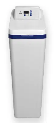
How to install, operate
and maintain your Demand
Controlled Water Softener
with Wi-Fi
Water Softener
Installation and Operation Manual
Model M45C
For best results use Morton
®
Clean
and Protect
®
or Morton
®
Clean
and Protect
®
Plus Rust Defense
®
Pellets in your water softener.
Manufactured and warranted by
Water Channel Partners
1890 Woodlane Drive
Woodbury, MN 55125
2 Morton
®
Water Softener Installation & Operation Manual
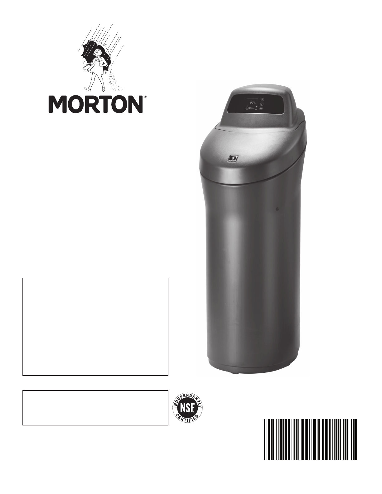
Protect your new water softener with
Morton
®
Clean and Protect
®
or Morton
®
Clean and Protect
®
Plus Rust Defense
®
Pellets
Morton
®
Water Softener Salt Pellets are made with a time-release
formula that works with your softener to help prevent mineral buildup
and keep your home’s pipes and appliances working at their best.
Whether you’re looking to remove iron and fight buildup, or extend your
water softener’s life, Morton
®
has the right salt for you. Use one or both
of our premium formula pellets in any water softener for the best results.
Remember to fill your water softener with Morton
®
America’s #1 Brand of Water Softener Salt!

Morton
®
Water Softener Installation & Operation Manual 3
TABLE OF CONTENTS
Page
I
nspect Shipment . . . . . . . . . . . . . . . . . . . . . . . . . . . . . . . . . . . . . . . . . . . . . . . . . . . . . . . . . . . . . . . . . . . . . . . . . . . . 4
Dimensions . . . . . . . . . . . . . . . . . . . . . . . . . . . . . . . . . . . . . . . . . . . . . . . . . . . . . . . . . . . . . . . . . . . . . . . . . . . . . . . . 4
Specifications & Performance Claims . . . . . . . . . . . . . . . . . . . . . . . . . . . . . . . . . . . . . . . . . . . . . . . . . . . . . . . . . . . . 5
Before You Start . . . . . . . . . . . . . . . . . . . . . . . . . . . . . . . . . . . . . . . . . . . . . . . . . . . . . . . . . . . . . . . . . . . . . . . . . . . . 6
W
ater Conditioning Information . . . . . . . . . . . . . . . . . . . . . . . . . . . . . . . . . . . . . . . . . . . . . . . . . . . . . . . . . . . . . . . . . 6
Installation Requirements . . . . . . . . . . . . . . . . . . . . . . . . . . . . . . . . . . . . . . . . . . . . . . . . . . . . . . . . . . . . . . . . . . . . 7-8
I
nstallation Instructions . . . . . . . . . . . . . . . . . . . . . . . . . . . . . . . . . . . . . . . . . . . . . . . . . . . . . . . . . . . . . . . . . . . . . 9-13
Programming the Softener . . . . . . . . . . . . . . . . . . . . . . . . . . . . . . . . . . . . . . . . . . . . . . . . . . . . . . . . . . . . . . . . . 14-16
Connecting the System to Wi-Fi . . . . . . . . . . . . . . . . . . . . . . . . . . . . . . . . . . . . . . . . . . . . . . . . . . . . . . . . . . . . 17-18
Controller Features . . . . . . . . . . . . . . . . . . . . . . . . . . . . . . . . . . . . . . . . . . . . . . . . . . . . . . . . . . . . . . . . . . . . . . 19-21
Routine Maintenance . . . . . . . . . . . . . . . . . . . . . . . . . . . . . . . . . . . . . . . . . . . . . . . . . . . . . . . . . . . . . . . . . . . . . 22-23
Troubleshooting . . . . . . . . . . . . . . . . . . . . . . . . . . . . . . . . . . . . . . . . . . . . . . . . . . . . . . . . . . . . . . . . . . . . . . . . . 24-25
Wiring Schematic . . . . . . . . . . . . . . . . . . . . . . . . . . . . . . . . . . . . . . . . . . . . . . . . . . . . . . . . . . . . . . . . . . . . . . . . . . 26
Optional Motorized Water Shutoff Valve . . . . . . . . . . . . . . . . . . . . . . . . . . . . . . . . . . . . . . . . . . . . . . . . . . . . . . . . . 27
Exploded View & Parts List . . . . . . . . . . . . . . . . . . . . . . . . . . . . . . . . . . . . . . . . . . . . . . . . . . . . . . . . . . . . . . . . 28-31
Warranty . . . . . . . . . . . . . . . . . . . . . . . . . . . . . . . . . . . . . . . . . . . . . . . . . . . . . . . . . . . . . . . . . . . . . . . . . . . . . . . . . 32
FCC NOTICE
NOTE: This equipment has been tested and found to
comply with the limits for a Class B digital device, pur-
suant to Part 15 of the FCC Rules. These limits are
designed to provide reasonable protection against
harmful interference in a residential installation. This
equipment generates, uses, and can radiate radio fre-
quency energy and, if not installed and used in accor-
dance with the instructions may cause harmful interfer-
ence to radio communications.
However, there is no guarantee that interference will
not occur in a particular installation. If this equipment
does cause harmful interference to radio or television
reception, which can be determined by turning the
equipment off and on, the user is encouraged to try to
correct the interference by one or more of the following
measures:
= Reorient or relocate the receiving antenna.
= Increase the separation between the equipment
and receiver.
= Connect the equipment into an outlet on a circuit
different from that to which the receiver is connected.
= Consult the dealer or an experienced radio/TV
technician for help.
IMPORTANT: Changes or modifications not expressly
approved by the party responsible for compliance
could void the user’s authority to operate the equip-
ment.
17"
21"
48"
41-1/2"
IN - OUT
34"
3-3/4"
INOUT
FRONT VIEW SIDE VIEW
4 Morton
®
Water Softener Installation & Operation Manual
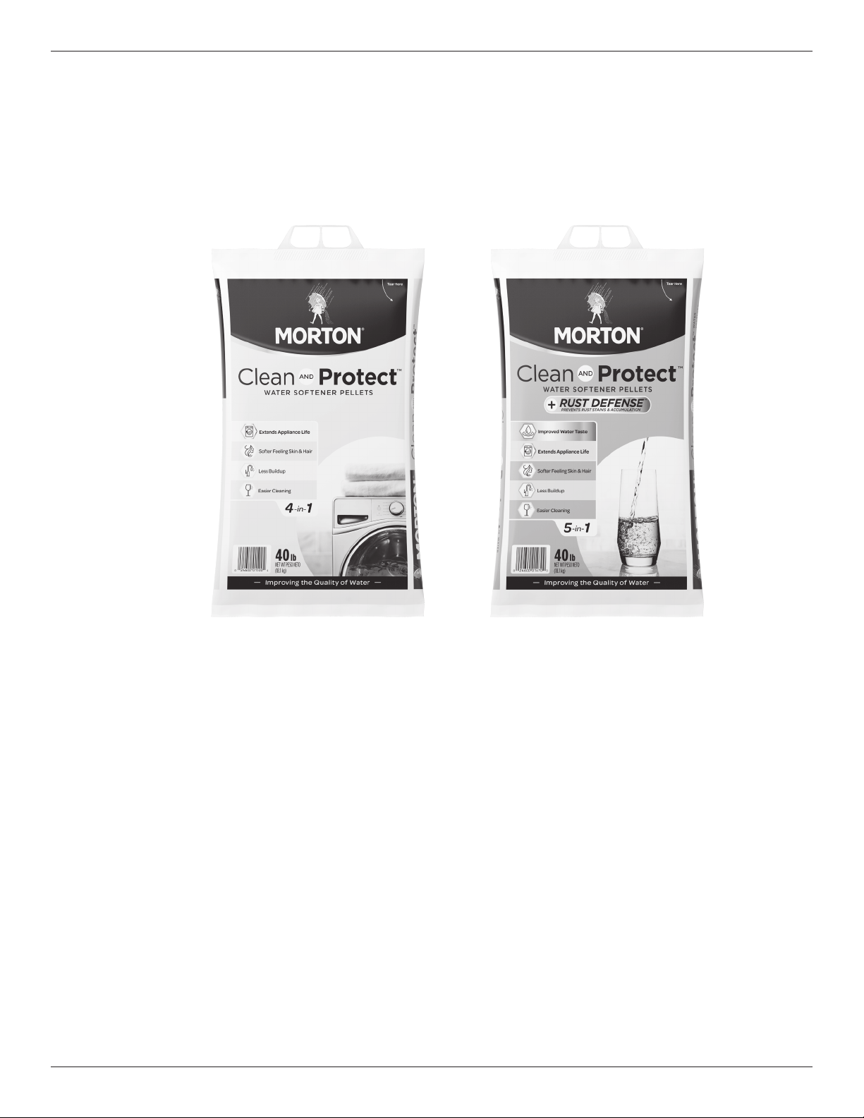
Packing List
Inspect Shipment
The parts required to assemble and install the unit are
included in a bag. Thoroughly check the water soften-
e
r for possible shipping damage and parts loss. Also
inspect and note any damage to the shipping carton.
FIG. 1
Remove and discard (or recycle) all packing materials.
To avoid loss of small parts, we suggest you keep the
s
mall parts in the parts bag until you are ready to use
them.
Do not return the water softener to store.
If you have any questions, or there are missing parts or damage, please call Toll Free 1-888-64 WATER
(1-888-649-2837).
When you call, please be prepared to provide the model and serial number of your product, found on the
rating decal, located on the rim below the salt lid hinges.
For more installation or service information, visit www.mortonwatersofteners.com.
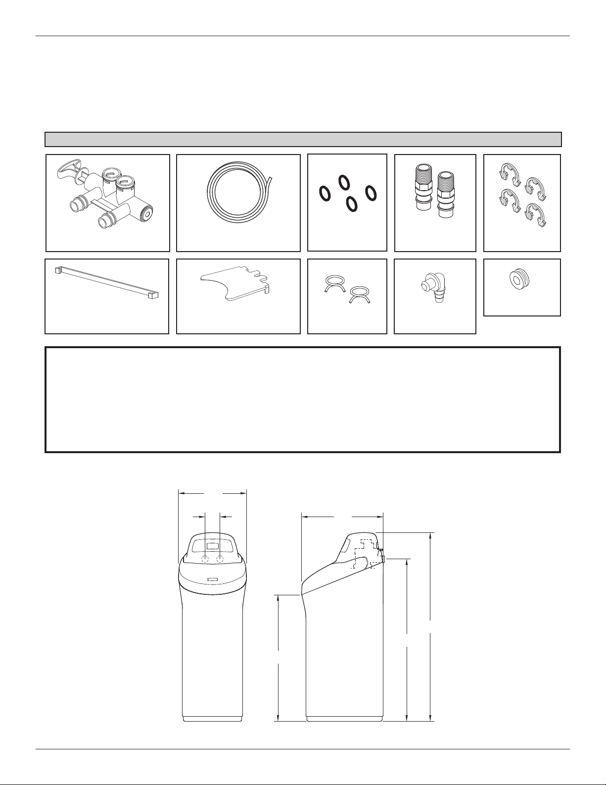
Dimensions
FIG. 2
OUT
IN
FRONT VIEW
SIDE VIEW
IN - OUT
41-1/2”
48”
34”
21”
Drain HoseBypass Valve
Adaptor Elbow
Installation
Adaptors
Hose Clamps
O-rings
Grommet
Cover Lock
(for shipping only)
Rim Insert
(for shipping only)
Clips
17”
3-3/4”
Morton
®
Water Softener Installation & Operation Manual 5
Specifications & Performance Claims
In the state of California: You must turn the Salt Efficiency Feature setting to ON. This may initiate
more frequent recharges. However, it will operate at 4,000 grains per pound of salt or higher. To turn
on the Salt Efficiency Feature, follow the instructions in the “Salt Efficiency” section of this manual.
This model is efficiency rated. The efficiency rating is valid only at the minimum salt dose. This system has a
demand initiated regeneration (D.I.R.) feature that complies with specific performance specifications intended to min-
i
mize the amount of regenerant brine and water used in their operation.
T
his water softener and filter has a rated softener efficiency of not less than 3,350 grains of total hardness exchange
per pound of salt (based on sodium chloride) and shall not deliver more salt than its listed rating or be operated at a
s
ustained maximum service flow rate greater than its listed rating. This system has been proven to deliver soft
water for at least ten continuous minutes at the rated service flow rate. The rated salt efficiency is measured by lab-
oratory tests described in NSF/ANSI Standard 44. These tests represent the maximum possible efficiency that the
system can achieve. Operational efficiency is the actual efficiency after the system has been installed. It is typically
less than the rated efficiency, due to individual application factors including water hardness, water usage, and other
contaminants that reduce a softener's capacity.
*Intermittent flow rate does not represent the maximum service flow rate used for determining
the softener’s rated capacity and efficiency. Continuous operation at flow rates greater than
the service flow rate may affect capacity and efficiency performance.
**Capacity to reduce clear water iron is substantiated by laboratory test data. State of Wisconsin
requires additional treatment if water supply contains clear water iron exceeding 5 ppm.
***Canada working pressure: 1.4 - 7.0 kg/cm².
This system conforms to NSF/ANSI Standard 44 for the specific performance claims as verified
and substantiated by test data.
Variable Salt Dose: The salt dose is selected by the electronic controls at regeneration time
based on the amount needed.
Model M45C
Model Code o45
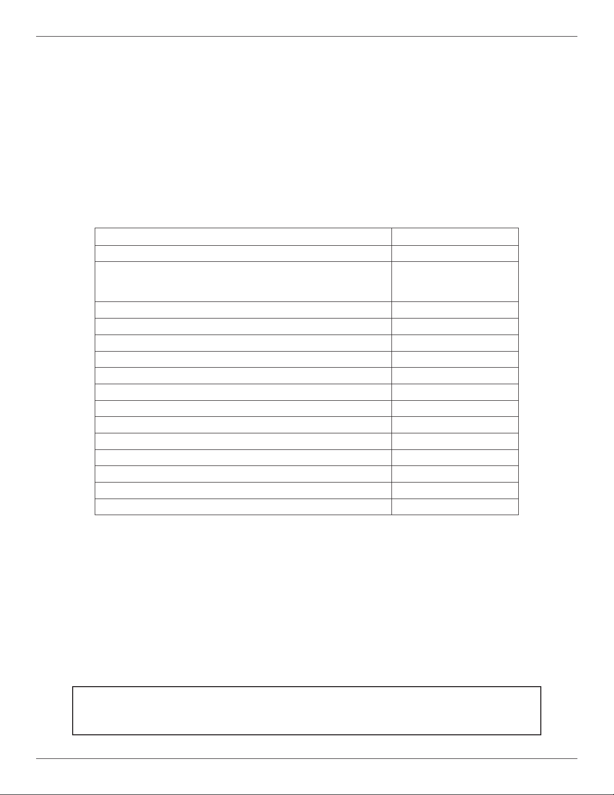
Rated Softening Capacity (Grains @ Salt Dose)
13,233 @ 2.6 lbs.
35,700 @ 9.9 lbs.
45,400 @ 17.2 lbs.
Rated Efficiency (Grains/Pound of Salt @ Minimum Salt Dose) 5,070 @ 2.6 lbs.
Water Used During Regeneration @ Minimum Salt Dose 4.3 gallons / 1,000 grains
Total Water Used Per Regeneration @ Maximum Salt Dose 43.7 gallons
Rated Service Flow Rate 10.0 gpm
Amount of High Capacity Ion Exchange Resin 1.26 cu. ft.
Pressure Drop at Rated Service Flow 11.2 psig
Intermittent Flow Rate @ 15 psi* 12.3 gpm
Water Supply Max. Hardness 120 gpg
Water Supply Max. Clear Water Iron 12 ppm**
Water Pressure Limits (min. / max.) 20 - 125 psi***
Water Temperature Limits (min. / max.) 40 - 120 °F
Minimum Water Supply Flow Rate 3 gpm
Maximum Drain Flow Rate 2.2 gpm

6 Morton
®
Water Softener Installation & Operation Manual
= The water softener requires a minimum water flow of 3 gallons per minute at the inlet. Maximum allowable inlet
water pressure is 125 psi. If daytime pressure is over 80 psi, nighttime pressure may exceed the maximum. Use
a pressure reducing valve if necessary (Adding a pressure reducing valve may reduce the flow). If your home is
equipped with a back flow preventer, an expansion tank must be installed in accordance with local codes and
l
aws.
= The water softener works on 24V DC electrical power, supplied by a direct plug-in power supply (included). Be
sure to use the included power supply and plug it into a nominal 120V, 60 Hz household outlet that is in a dry
location only, grounded and properly protected by an overcurrent device such as a circuit breaker or fuse.
= Do not use this system to treat water that is microbiologically unsafe or of unknown quality without adequate dis-
infection upstream or downstream of the system.
European Directive 2002/96/EC requires all electrical and electronic equipment to be disposed of accord-
ing to Waste Electrical and Electronic Equipment (WEEE) requirements. This directive or similar laws are
in place nationally and can vary from region to region. Please refer to your state and local laws for prop-
er disposal of this equipment.
Before You Start
Water Conditioning Information
Iron
Iron in water can cause stains on clothing and plumb-
ing fixtures. It can negatively affect the taste of food,
drinking water, and other beverages. Iron in water is
measured in parts per million (ppm). The total* ppm of
iron, and type or types*, is determined by chemical
analysis. Four different types of iron in water are:
= Ferrous (clear water) iron
= Ferric (red water) iron
= Bacterial and organically bound iron
= Colloidal and inorganically bound iron (ferrous or
ferric)
Ferrous (clear water) iron is soluble and dissolves in
water. This water softener will reduce moderate
amounts of this type of iron (see specifications).**
Ferrous (clear water) iron is usually detected by taking
a sample of water in a clear bottle or glass.
Immediately after taking, the sample is clear. As the
water sample stands, it gradually clouds and turns
slightly yellow or brown as air oxidizes the iron. This
usually occurs in 15 to 30 minutes.
When using the softener to reduce Ferrous (clear
water) iron, add 5 grains to the hardness setting for
every 1 ppm of Ferrous (clear water) iron. See "Set
Water Hardness Number" section.
Ferric (red water), and bacterial and organically bound
irons are insoluble. This water softener will not
remove ferric or bacterial iron. This iron is visible
immediately when drawn from a faucet because it has
oxidized before reaching the home. It appears as
small cloudy yellow, orange, or reddish suspended
particles. After the water stands for a period of time,
the particles settle to the bottom of the container.
Generally these irons are removed from water by filtra-
tion. Chlorination is also recommended for bacterial
iron.
Colloidal and inorganically bound iron is of ferric or fer-
rous form that will not filter or exchange out of water.
This water softener will not remove colloidal iron. In
some instances, treatment may improve colloidal iron
water. Colloidal iron water usually has a yellow
appearance when drawn. After standing for several
hours, the color persists and the iron does not settle,
but remains suspended in the water.
Sediment
Sediment is fine, foreign material particles suspended
in water. This material is most often clay or silt.
Extreme amounts of sediment may give the water a
cloudy appearance, and may require a sediment filter
be installed upstream of the water softener.
* Water may contain one or more of the four types of
iron and any combination of these. Total iron is the
sum of the contents.
** Capacity to reduce clear water iron is substantiated
by laboratory test data.
Morton
®
Water Softener Installation & Operation Manual 7
Installation Requirements
Plumbing Codes
A
ll plumbing must be completed in accordance with
national, state and local plumbing codes.
Laundry Tub
Standpipe
1-1/2”
air gap
Floor Drain
In the state of Massachusetts: The Commonwealth
of Massachusetts plumbing code 248-CMR shall
be adhered to. A licensed plumber shall be used
for this installation.
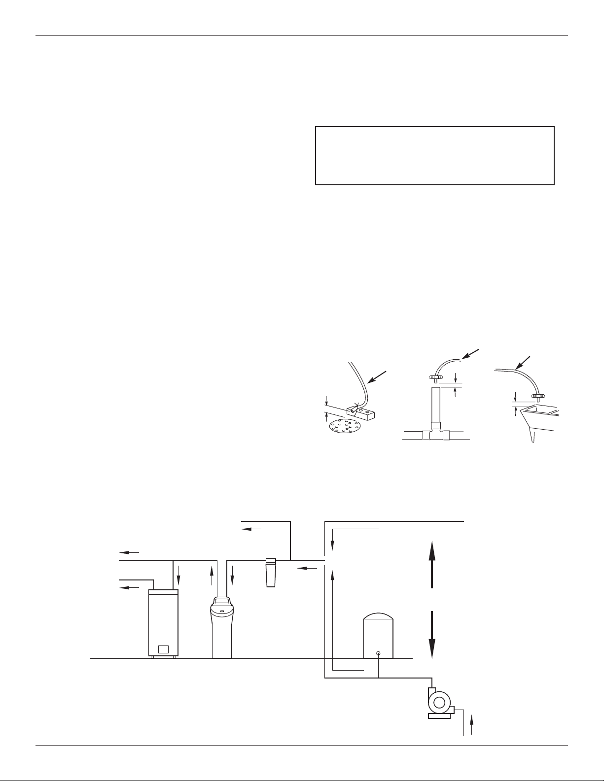
Air Gap Requirements
A drain is needed for the water discharged from the
valve during the softener’s regeneration cycle (See
Figure 3). A floor drain, close to the water softener, is
preferred. A laundry tub, standpipe, etc. are other
drain options. Secure valve drain hose in place.
Leave an air gap of 1-1/2” between the end of the
hose and the drain. This gap is needed to prevent
backflow of sewer water into the water softener. Do
not put the end of the drain hose into the drain.
FIG. 3
1-1/2”
air gap
Drain
Hose
Drain
Hose
1-1/2”
air gap
Location Requirements
C
onsider all of the following when selecting an installa-
tion location for the water softener.
= Do not locate the water softener where freezing
t
emperatures occur. Do not attempt to treat water
over 120ºF. Freezing temperatures or hot water
damage voids the warranty.
= To condition all water in the home, install the water
softener close to the water supply inlet, and
upstream of all other plumbing connections, except
outside water pipes. Outside faucets should remain
on hard water to avoid wasting conditioned water
and salt.
= A nearby drain is needed to carry away regenera-
tion discharge (drain) water. Use a floor drain,
laundry tub, sump, standpipe, or other options
(check your local codes). See "Air Gap
Requirements" and "Valve Drain Requirements"
sections.
= The water softener works on 24V DC electrical
power, supplied by a direct plug-in power supply
(included). Provide nearby a 120V, 60Hz electrical
outlet in accordance with NEC and local codes.
= Always install the water softener between the water
inlet and water heater. Any other installed water
conditioning equipment should be installed between
the water inlet and water softener (See Figure 4
below).
= Avoid installing in direct sunlight. Excessive sun
heat may cause distortion or other damage to non-
metallic parts.
The Proper Order To Install Water Treatment Equipment
FIG. 4
Pressure
Tank
City Water Supply
Well Water Supply
Well
Pump
OR
Optional
Sediment
Filter
Water
Heater
Water
Softener
Untreated Water to
Outside Faucets
Hot Water
to House
Cold Water
to House
Drain
Hose
8 Morton
®
Water Softener Installation & Operation Manual
Installation Requirements
Valve Drain Requirements
U
sing the flexible drain hose (included), measure and
cut to the length needed. Flexible drain hose is not
allowed in all localities (check your plumbing codes). If
local codes do not allow use of a flexible drain hose, a
rigid valve drain run must be used. Purchase a com-
pression fitting (1/4 NPT x 1/2 in. minimum tube) and
1/2" tubing from your local hardware store. Plumb a
rigid drain as needed (See Figure 6).
NOTE: Avoid drain hose runs longer than 30 feet.
Avoid elevating the hose more than 8 feet
above the floor. Make the valve drain line as
short and direct as possible.
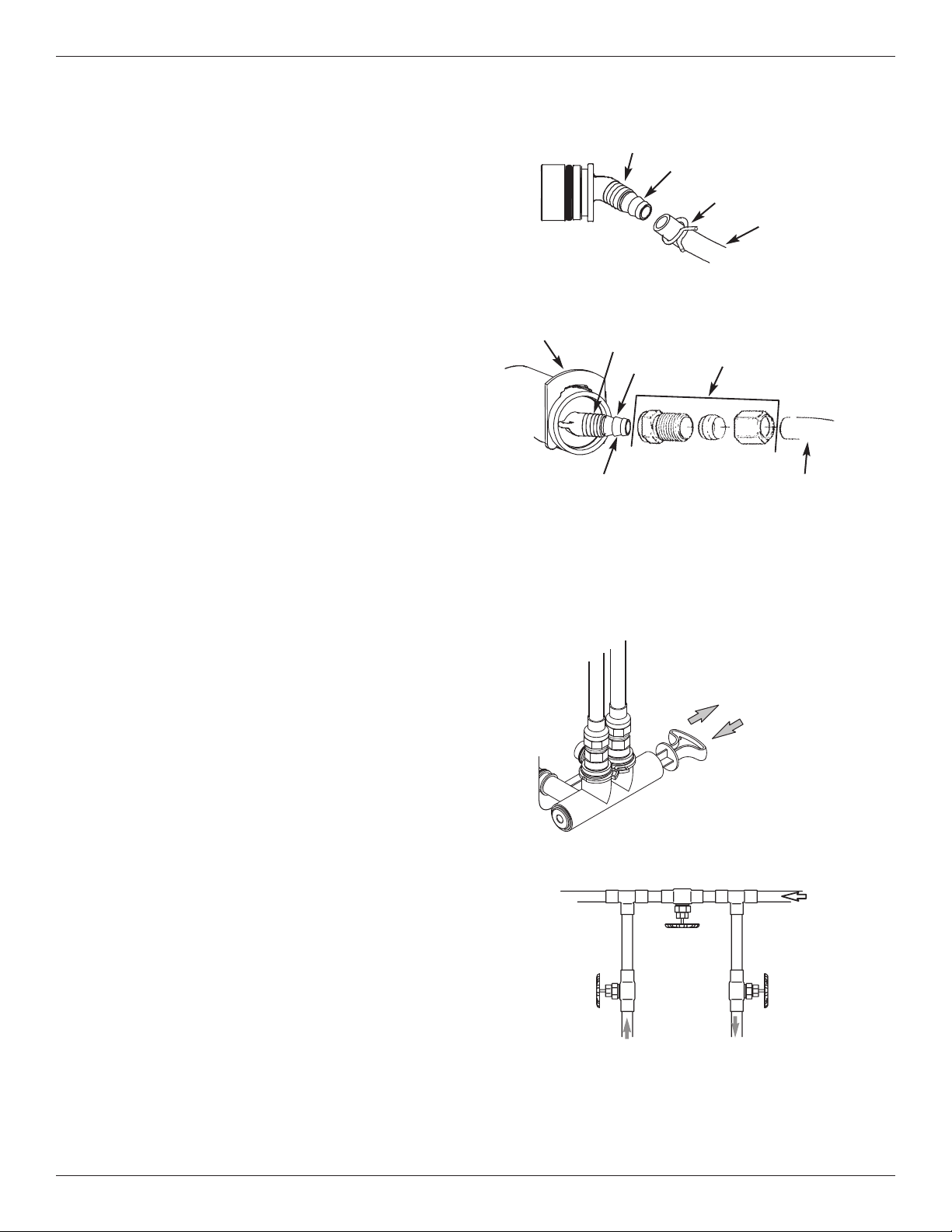
Inlet / Outlet Plumbing Options
Always install either a single bypass valve (provided),
as shown in Figure 7, or, if desired, parts for a 3 valve
bypass system (not included) can be purchased and
assembled, as shown in Figure 8. Bypass valves
allow you to turn off water to the softener for mainte-
nance if needed, but still have water in house pipes.
Pipe fittings must be 3/4” minimum.
Use:
= Copper pipe
= Threaded pipe
= PEX (Crosslinked Polyethylene) pipe
= CPVC plastic pipe
= Other pipe approved for use with potable water
IMPORTANT: Do not solder with plumbing attached to
installation adaptors and single bypass
valve. Soldering heat will damage the
adaptors and valve.
FIG. 8
Single Bypass Valve
3 Valve Bypass
From Water
Softener
To Water
Softener
Inlet
Valve
Outlet
Valve
Bypass
Valve
FIG. 7
Pull out for “Service”
(Soft water)
Push in for
“Bypass”
FIG. 5
FIG. 6
1/4” NPT
Thread
Clip
Barbs
1/4 NPT
Threads
1/2” Outside Dia.
Copper Tube
(not included)
Compression Fitting.
1/4 NPT x 1/2” O.D.
Tube (not included)
Cut barbs from drain fit-
ting (pull clip to remove
fitting from valve)
Barbs for 3/8”
I.D. Tubing
Drain Hose
Hose Clamp
Morton
®
Water Softener Installation & Operation Manual 9
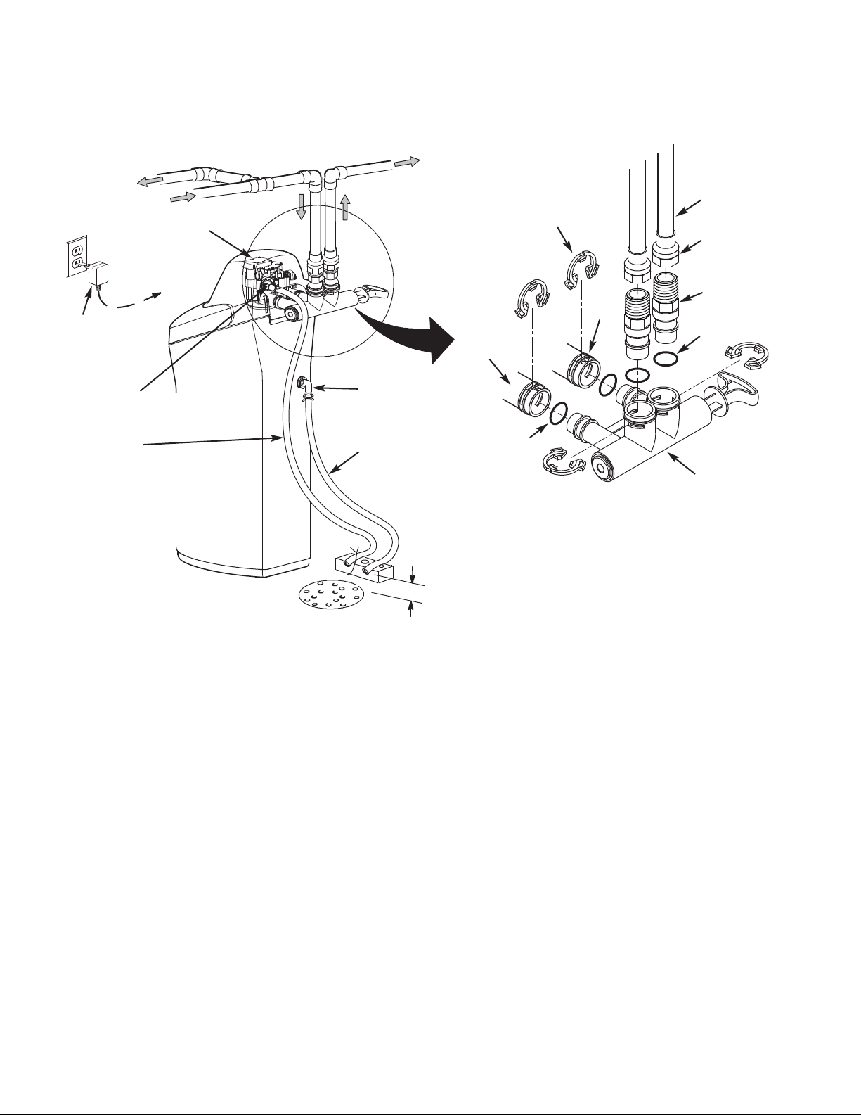
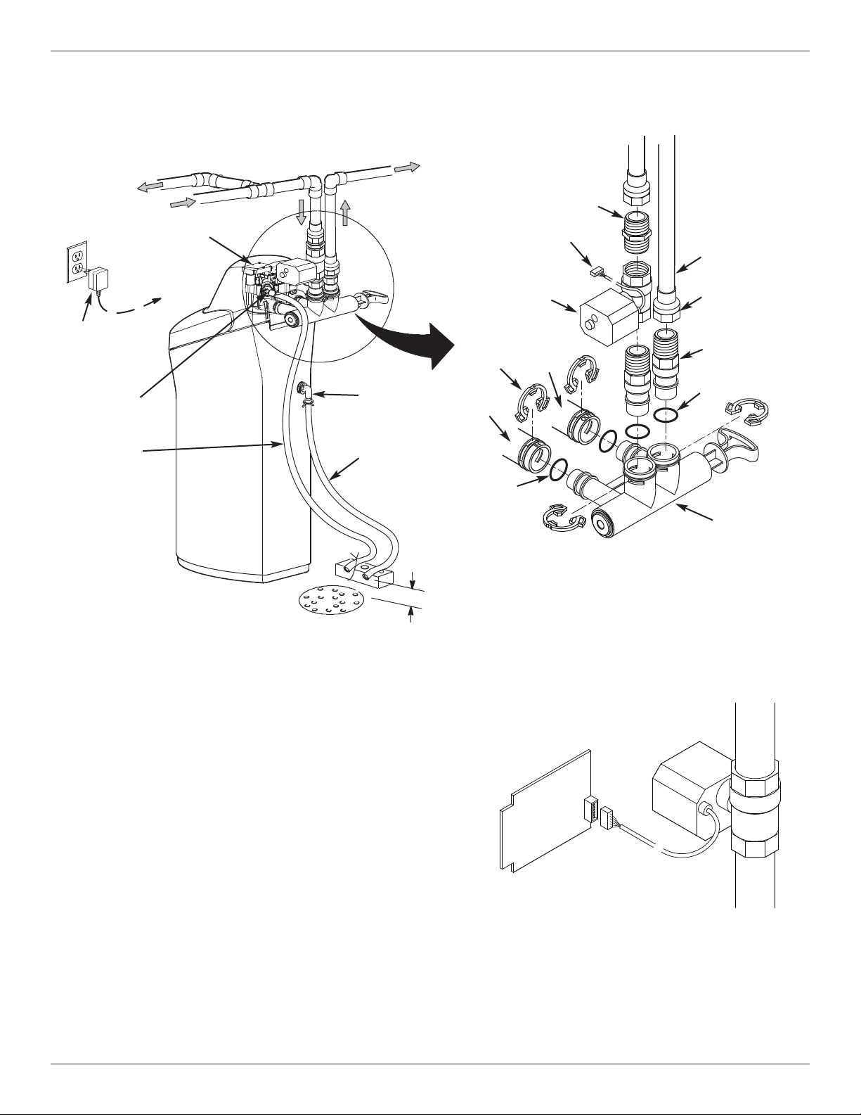
Installation Instructions
TYPICAL INSTALLATION
FIG. 9A
NOTE: See “Air Gap Requirements” section.
NOTE: Water Softener shown with Salt Lid and
Top Cover removed
Inlet
Outlet
Clips
Pipe
To Outside
F
aucets
1” NPT Sweat
A
daptor (not
included)
O-ring
Single
Bypass Valve
Lubricated
O-ring
Soft
Water
Hard Water
M
a
i
n
W
ate
r
Pi
pe
Water Softener
Valve
Valve Drain
Elbow
Valve Drain
Hose*
*Do not connect the
water softener valve drain
tubing to the salt storage
tank overflow hose.
Floor Drain
Overflow
Drain Elbow
Salt Storage
Tank Overflow
Hose*
Secure Valve Drain
Hose in place over
Floor Drain
1” NPT
Threaded
Adaptor
1-1/2”
air gap
Plug-in
Power
Supply
To
Controller
Step 1. Turn Off Water Supply
1. Close the main water supply valve, located near the
well pump or water meter.
2. Shut off the electric or fuel supply to the water
heater.
3. Open all faucets to drain all water from house pipes.
NOTE: Be sure not to drain water from the water
heater, as damage to the water heater ele-
ments could result.
Step 2. Assembly
1. Morton
®
water softener models are factory assem-
bled. During installation, unsnap and remove the
top cover, together with the salt lid, to expose the
softener valve assembly. Set them aside to prevent
damage. Check the brinewell to be sure it is
secured and vertical (See Figure 11).
2. Install the brine tank overflow grommet and elbow
into the 13/16” diameter hole in the back of the salt
storage tank wall (See Figure 11).
Step 3. Move the Unit into Place
1. Move the water softener into the desired location.
Set it on a solid, level surface.
IMPORTANT: Do not place shims directly under the
salt storage tank to level the softener.
The weight of the tank, when full of
water and salt, may cause the tank to
fracture at the shim.
2. Visually check and remove any debris from the
water softener valve inlet and outlet ports.
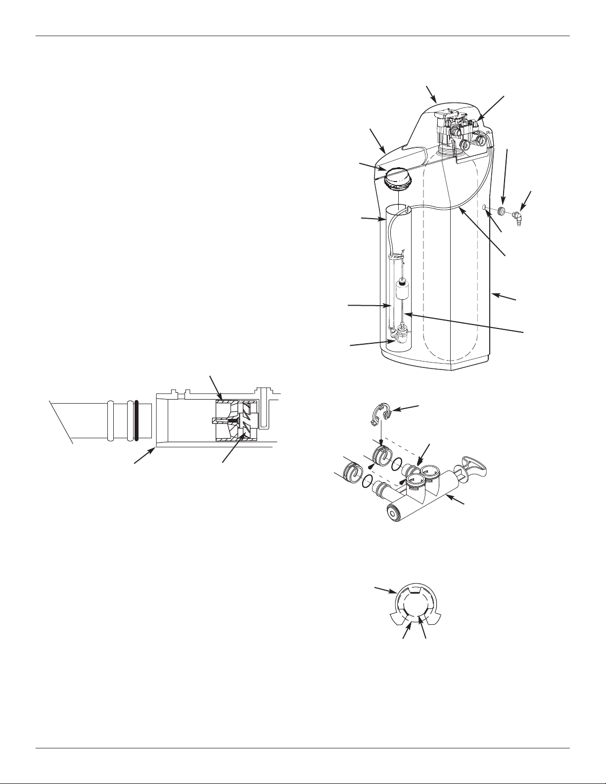
3. Make sure the turbine assembly spins freely in the
"out" port of the valve (See Figure 10).
4. If not already done, put a light coating of silicone
grease on the single bypass valve o-rings.
5. Push the single bypass valve into the softener valve
as far as it will go. Snap the two large holding clips
into place, from the top down as shown in Figures
12 & 13.
IMPORTANT: Be sure the clips snap firmly into place
so the single bypass valve will not pull
out.
10 Morton
®
Water Softener Installation & Operation Manual
TYPICAL INSTALLATION (with optional motorized water shutoff valve)
FIG. 9B
NOTE: See “Air Gap Requirements” section.
NOTE: Water Softener shown with Salt Lid and
Top Cover removed
Inlet
Outlet
Clips
Pipe
To Outside
F
aucets
1” NPT Sweat
Adaptor (not
included)
O-ring
Single
Bypass Valve
Lubricated
O-ring
Soft
Water
Hard Water
M
a
i
n
W
ate
r
Pi
pe
Water Softener
Valve
Valve Drain
Elbow
Valve Drain
Hose*
*Do not connect the
water softener valve drain
tubing to the salt storage
tank overflow hose.
Floor Drain
Overflow
Drain Elbow
Salt Storage
Tank Overflow
Hose*
Secure Valve Drain
Hose in place over
Floor Drain
1” NPT
Threaded
Adaptor
1-1/2”
air gap
Plug-in
Power
Supply
To
Controller
Installation Instructions
Optional Motorized
Water Shutoff Valve
(not included with
water softener)
1” NPT Nipple
(
provided with
optional motorized
water shutoff valve)
Plug into Controller
Optional Motorized
Water Shutoff Valve
Electronic Control
Board on back of
Faceplate
Plug cable into elec-
tronic control board
(power must be off)
FIG. 9C
Step 4. (Optional) Install the Motorized Water Shutoff Valve
If you purchased the optional water shutoff valve,
install it in the plumbing upstream of the softener inlet.
Figure 9B shows installation with the shutoff valve
immediately upstream of the bypass valve inlet, using
one of the softener’s installation adaptors and the 1”
NPT nipple provided with the shutoff valve.
The shutoff valve may also be installed in the plumbing
farther upstream of the softener, making sure that the
10 foot long cable will reach the softener’s electronic
control board (See Figure 9C). The shutoff valve’s
inlet and outlet are female 1” NPT. Support the weight
of the shutoff valve.
After completing plumbing, make sure that the water
softener is not powered up, and plug the cable from
the shutoff valve into the corresponding connector on
the electronic control board (See Fig. 9C or Schematic
on Page 26).
CAUTION: Do not place fingers into the motorized
shutoff valve when it is plugged into the electronic con-
troller.
NOTE: The shutoff valve may be operated manually
by pulling out and turning the knob on the shutoff valve
body (See Fig. 64 on Page 27), although there is no
need to do this when installing.
Morton
®
Water Softener Installation & Operation Manual 11
Installation Instructions
FIG. 13
Correct Assembly
Clip
Outside diameter
of clip channel on
single bypass valve
Outside diameter
of water softener
valve inlet & outlet
NOTE: Be sure all 3 tabs of the clip go through the matching
holes on the water softener valve inlet or outlet, and
fully into the channel on the single bypass valve.
Make sure that the tabs are fully seated.
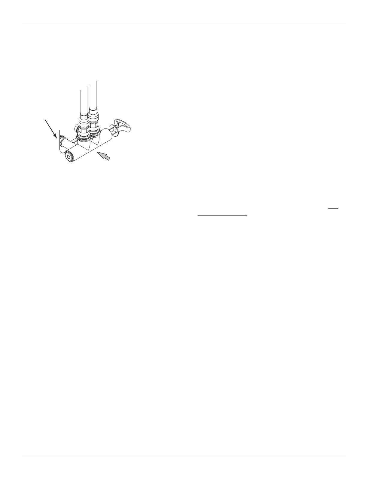
Step 5. Complete Inlet and Outlet
Plumbing
Measure, cut, and loosely assemble pipe and fittings
from the main water pipe to the inlet and outlet ports of
t
he water softener valve. Be sure to keep fittings fully
together, and pipes squared and straight.
Be sure hard water supply pipe goes to the water sof-
tener valve inlet side.
NOTE: Inlet and outlet are marked on the water sof-
tener valve. Trace the water flow direction to
be sure hard water is to inlet.
IMPORTANT: Be sure to fit, align and support all
plumbing to prevent putting stress on
the water softener valve inlet and outlet.
Undue stress from misaligned or unsup-
ported plumbing may cause damage to
the valve.
Complete the inlet and outlet plumbing for the type of
pipes you will be using.
FIG. 11
Top Cover
Brine Tank
Overflow
Elbow
Brine Tank
Overflow
Grommet
13/16” Hole
Salt Lid
Salt
Storage
Tank
Float
Stem
Brine
Tubing
Brinewell
C
over
Stand
Tube
Brine
Valve
Brinewell
Nozzle & Venturi
Assembly
FIG. 10
Turbine
Support
Valve Outlet Turbine
FIG. 12
Clip
Channel
Single Bypass Valve
12 Morton
®
Water Softener Installation & Operation Manual
Installation Instructions
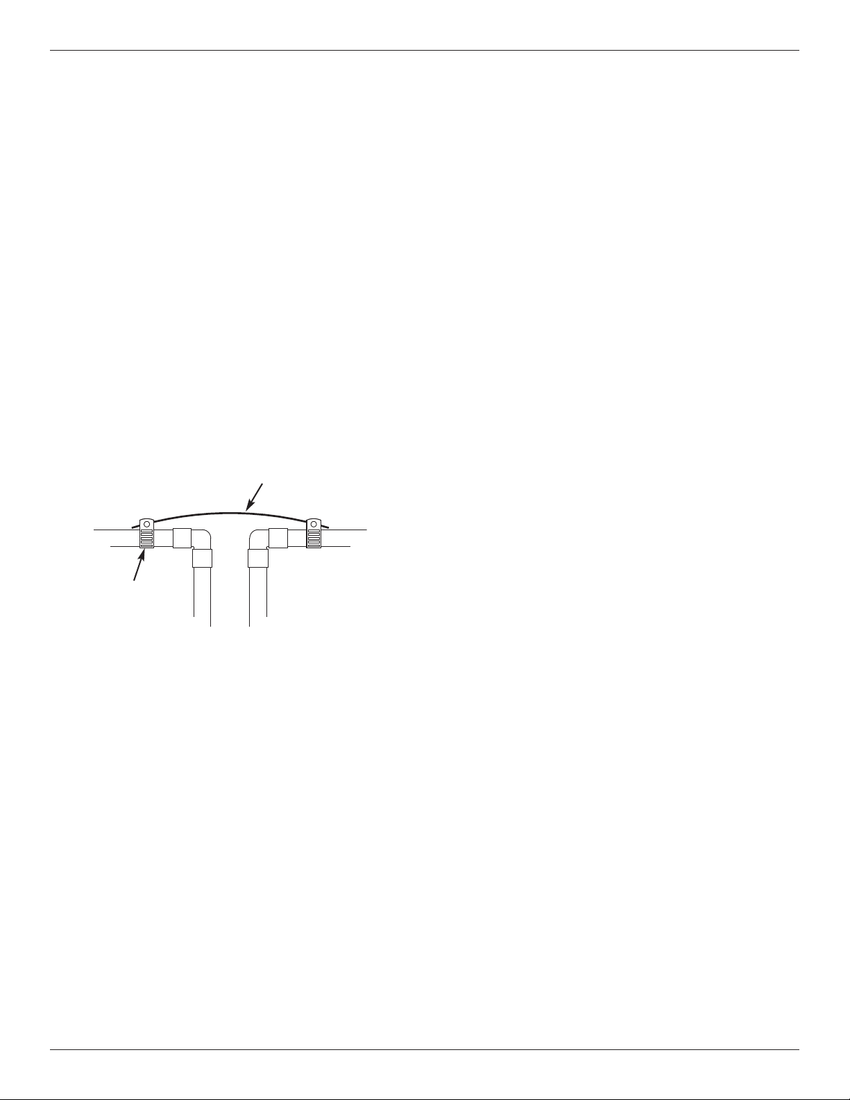
Step 6. Cold Water Pipe Grounding
C
AUTION: The house cold water pipe (metal only)
is often used as a ground for the house
electrical system, The 3-valve bypass
type of installation, shown in Figure 8,
will maintain ground continuity. If you
use a plastic bypass valve at the unit,
continuity is broken. To restore the
ground, do the following:
1. Install a #4 copper wire across the removed section
of main water pipe, securely clamping it at both
ends (See Figure 14) - parts not included.
NOTE: Check local plumbing and electrical codes
for proper installation of the ground wire.
The installation must conform to them. In
Massachusetts, plumbing codes of
Massachusetts shall be conformed to.
Consult with your licensed plumber.
FIG. 14
Ground
Wire
Clamp (2)
Step 8. Install Salt Storage Tank
Over flow Hose
1. Measure, cut to needed length and connect the 3/8"
drain line (provided) to the salt storage tank over-
f
low elbow and secure in place with a hose clamp.
2 Run the hose to the floor drain, or other suitable
drain point no higher than the drain fitting on the salt
storage tank (This is a gravity drain). If the tank
overfills with water, the excess water flows to the
drain point. Cut the drain line to the desired length
and route it neatly out of the way.
IMPORTANT: For proper operation of the water soften-
er, do not connect the water softener
valve drain hose from Step 7 to the salt
storage tank overflow hose.
Step 9. Pressure Testing for Leaks
To prevent air pressure in the water softener and
plumbing system, do the following steps exactly in
order:
1. Fully open two or more softened cold water faucets
nearby the water softener, located downstream from
the water softener.
2. Place the single bypass valve or 3 valve bypass in
"bypass" position. See Figures 7 & 8.
3. Fully open the main water supply valve. Run water
until there is a steady flow from the opened faucets,
with no air bubbles.
4. Place bypass valve(s) in "service" or soft water posi-
tion exactly as follows:
= Single bypass valve: Slowly move the valve stem
toward "service," pausing several times to allow
the water softener to fill with water.
= 3 valve bypass: Fully close the bypass valve and
open the outlet valve. Slowly open the inlet
valve, pausing several times to allow the water
softener to fill with water.
5. After about three minutes, open a hot water faucet
until there is a steady flow and there are no air bub-
bles, then close this faucet.
6. Close all cold water faucets and check for leaks at
the plumbing connections that you made.
7. Check for leaks around clips at softener’s inlet and
outlet. If a leak occurs at a clip, depressurize the
plumbing (turn off the water supply and open
faucets) before removing clip. When removing clips
at the softener’s inlet or outlet, push the single
Step 7. Install Valve Drain Hose
NOTE: See valve drain options on pages 7 & 8.
1. Measure, cut to needed length and connect the 3/8"
drain line (provided) to the water softener valve
drain fitting. Use a hose clamp to hold the hose in
place.
IMPORTANT: If codes require a rigid drain line see
“Valve Drain requirements" section.
2. Run the drain hose (or a rigid line) to the floor drain.
Secure drain hose. This will prevent “whipping'' dur-
ing regenerations. Be sure to provide a 1-1/2”
minimum air gap to prevent possible sewer
water backup. See “Air Gap Requirements" sec-
tion.
NOTE: In addition to a floor drain, you can use a laun-
dry tub or standpipe as a good drain point for
this hose.. Avoid long drain hose runs, or ele-
vating the hose more than 8’ above the floor.
continued on next page
Morton
®
Water Softener Installation & Operation Manual 13
Installation Instructions
bypass valve body toward the softener (See Figure
15). Improper removal may damage clips. Do not
reinstall damaged clips.
c
ontinued from previous page
Questions? Call Toll Free 1-888-64 WATER (1-888-649-2837)
or visit www.mortonwatersofteners.com
When you call, please be prepared to provide the model and serial number,
found on the rating decal, located on the rim below the salt lid hinges.
Step 10. Add Water and Salt to the
Salt Storage Tank
1. Using a container, add about three gallons of clean
water into the salt storage tank.
2. Add Morton
®
Clean and Protect
™
or Clean and
Protect
™
Plus Rust Defense
™
Pellets to the storage
tank.
NOTE: See Page 19 for additional information on
salt.
Step 11. Plug in the Power Supply
During installation, the water softener wiring may be
moved or jostled from place. Check to be sure all
leadwire connectors are secure on the back of the
electronic board and be sure all wiring is away from
the valve gear and motor area, which rotates during
regenerations.
1. Plug the water softener’s power supply into an elec-
trical outlet that is not controlled by a switch and is
approved by local codes.
Step 12. Program the Controller
1
. Install the softener’s top cover and salt lid.
2
. Complete the programming steps on pages 14-16.
Step 13. Sanitizing the Softener
Care is taken at the factory to keep your unit clean and
sanitary. Materials used to make the unit will not infect
or contaminate your water supply, and will not cause
bacteria to form or grow. However, during shipping,
storage, installation and operation, bacteria could get
into the unit. For this reason, sanitizing as follows is
suggested* when installing.
1. Open salt lid, remove the brinewell cover and pour
about 3 oz. (6 tablespoons) of household bleach
into the softener brinewell. Replace the brinewell
cover.
2 Make sure the bypass valve(s) is in the “service”
(open) position.
3 Start a recharge: Press the RECHARGE button and
hold for 3 seconds, until “RECHARGE NOW” begins
to flash in the display. This recharge draws the sani-
tizing bleach into and through the water softener.
Any air remaining in the unit is purged to the drain.
4 After the recharge has completed, fully open a cold
water faucet, downstream from the softener, and
allow 50 gallons of water to pass through the sys-
tem. This should take at least 20 minutes. Close
the faucet.
*Recommended by the Water Quality Association. On some
water supplies, the unit may need periodic disinfecting.
Step 14. Restart the Water Heater
Turn on the electricity or fuel supply to the water
heater and relight the pilot, if applicable.
NOTE: The water heater is filled with hard water and,
as hot water is used, it refills with conditioned
water. In a few days, the hot water will be fully
conditioned. To have fully conditioned hot
water immediately, wait until the initial recharge
(Step 13) is over. Then, drain the water heater
(following instructions for water heater) until
water runs cold.
FIG. 15
...depressurize the
plumbing, then push
Bypass Valve body
toward softener
If removing
clips...
14 Morton
®
Water Softener Installation & Operation Manual
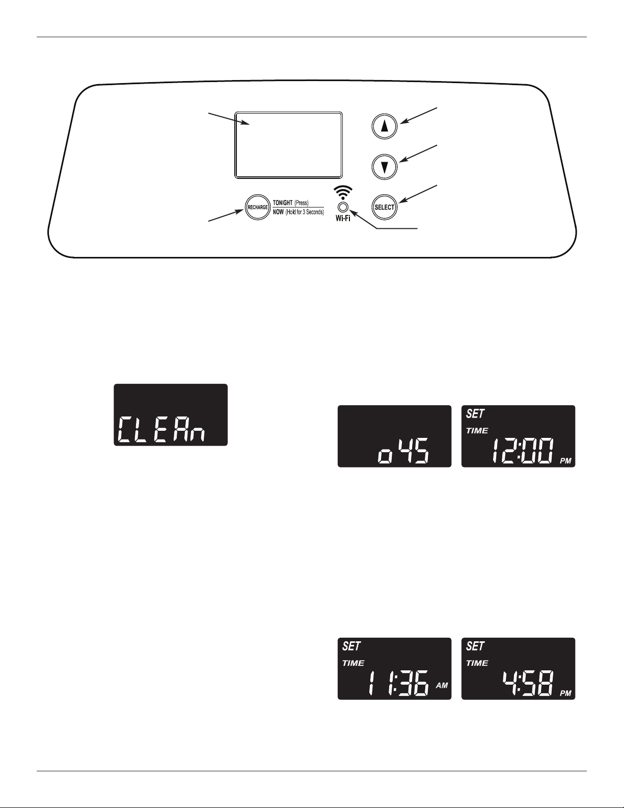
FIG. 17
Clean Reminder
The screen in Figure 17 appears, with “CLEAn” flash-
ing in the display, when four months have elapsed on
the system’s timer since start up or the last reset.
This is a reminder to use Morton
®
MWSC Water
Softener Cleanser three times a year. To reset the
timer, press any button on the control panel and
“CLEAn” will disappear.
Program the Softener
When the power supply is plugged into the electrical
outlet, the model code (o45) and a software version
number (example: r4.1), are briefly shown in the face-
plate display. Then the words “SET TIME” appear
and “12:00 PM” begins to flash.
NOTE: If “- - - -” shows in the display, press the
p
UP or
q
DOWN button until the model code
shows in the display. Then, press the
SELECT button to set, and change to the
flashing “SET TIME" display.
Step 1. Set Time of Day
If the words “SET TIME" do not show in the display,
press the SELECT button several times until they do.
Programming the Water Softener
FIG. 18
FIG. 19
continued on next page
FIG. 16
CONNECTION
STATUS light
UP button
DOWN
b
utton
Display
RECHARGE
button
SELECT
button
Morton
®
Water Softener Installation & Operation Manual 15
Programming the Water Softener
FIG. 20
continued from previous page
1. Press the
p
UP or
q
DOWN buttons to set the
present time. Up moves the display ahead; down
sets the time back. Be sure AM or PM is correct.
NOTE: Press buttons and quickly release to slowly
advance the display. Hold the buttons down
for fast advance.
NOTE: On Wi-Fi connected systems, the current time
will be updated and maintained automatically
via Wi-Fi.
2. When the correct time is displayed, press the
SELECT button, and the display will change to
show the “Hardness” screen.
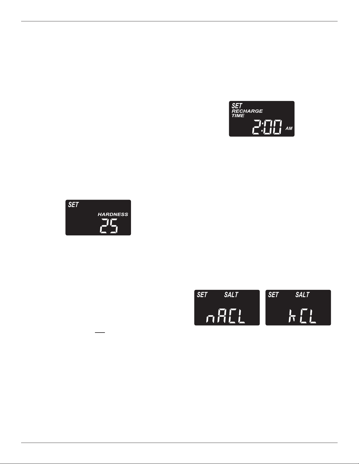
Step 2. Set Water Hardness Number
If you completed the previous step, the words “SET
HARDNESS" should show in the display. Otherwise,
press the SELECT button several times until they do.
FIG. 21
1. The softener’s default recharge start time is 2:00
AM. This is normally a time of day when water is
not being used in the household. Hard water
bypasses the softener if the household draws
water during the recharge cycle. If a different
recharge start time is desired, press the
p
UP or
q
DOWN buttons to change the time, in 1-hour
increments. Be sure AM or PM is correct.
2. When the desired recharge start time is displayed,
press the SELECT button, and the display will
change to show one of the “Salt Type” screens
shown below.
Step 4. Set Salt Type
If you completed the previous step, either “nACL” (for
Sodium Chloride) or “kCL” (for Potassium Chloride)
should show in the display. Otherwise, press the
SELECT button several times until one of them does.
1. Press the
p
UP or
q
DOWN buttons to set the type
of salt you will be using in your water softener.
The default is NaCl (standard Sodium Chloride
water softener salt). If you will be using KCl
(Potassium Chloride) instead, be sure to set salt
type to KCl. This setting adjusts the regeneration
cycle times to compensate for the different rate at
which KCl dissolves. See also Page 22 for more
information on salt types.
2. When the correct salt type is displayed, press the
SELECT button, and the display will change to
show the “Set Salt Level” screen.
FIG. 22
1. Press the
p
UP or
q
DOWN buttons to set the
hardness of your water supply, in grains per gallon.
The default is 25.
NOTE: If your water supply contains iron, compen-
sate for it by adding to the water hardness
number. For example, assume your water is
20 gpg hard and contains 2 ppm iron. Add 5
to the hardness number for each 1 ppm of
iron. In this example, you would use 30 for
your hardness number.
20 gpg hardness
2 ppm iron x 5 = 10 +10
(times) 30 HARDNESS NUMBER
2. When finished setting your water’s hardness num-
ber, press the SELECT button, and the display will
change to show the “Recharge Time” screen.
Step 3. Set Recharge (Regeneration)
Start Time
If you completed the previous step, the words
“SET RE CHARGE TIME" should show in the display.
O
therwise, press the SELECT button several times
until they do.
16 Morton
®
Water Softener Installation & Operation Manual
The softener enters the fill cycle of regeneration
immediately. This regeneration will take about 2 hours
to complete. Then, you will have soft water again.
NOTE: If the “Clean Feature” is set ON, the normal
regeneration cycle is preceded by a cleaning
backwash and rinse.
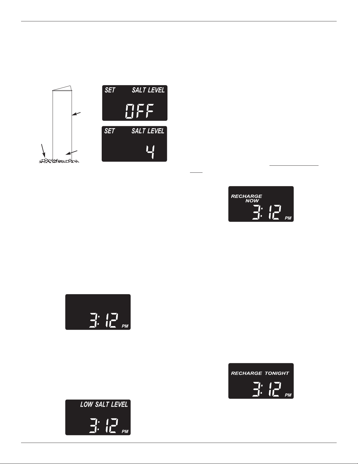
Recharge Tonight
If you do not want to start an immediate recharge, but
would like an extra recharge at the next preset
recharge start time, do the following to schedule a
recharge:
Press and release (do not hold) the RECHARGE but-
ton. “RECHARGE TONIGHT” will begin flashing in
the display, and the softener will begin regeneration
at the next preset recharge time (2:00 AM, or as set).
FIG. 26
FIG. 27
FIG. 25
8
7
6
5
4
FIG. 23
Salt
Level
Brine-
well
Num -
bers
Programming the Water Softener
Step 5. Set Salt Level
If you completed the previous step, the words
“SET SALT LEVEL" should show in the display.
O
therwise, press the SELECT button until they do.
1. Lift the salt lid and level the salt in the storage
tank.
2. The salt level scale, on the brinewell inside the
tank, has numbers from 0 to 8 (see Fig. 23).
Observe the highest number the leveled salt is at,
or closest to.
3. Press the
p
UP or
q
DOWN buttons until the num-
ber on the screen corresponds to the salt level. At
level 2 or below, “LOW SALT LEVEL" will flash in
the display. If you wish to turn this feature off,
press the
q
DOWN button past 0, and the word
“OFF” flashes in the display.
4. When finished setting the salt level, press the
SELECT button. The display returns to the normal
time of day screen (Fig. 24).
Salt Level Monitor System
You must set salt level each time salt is added to
the water softener. The salt monitor system esti-
mates salt levels, and accuracy will vary with different
salts. At level 2 or below, “LOW SALT LEVEL" will
flash in the display (Fig. 25) to remind you to add salt.
Extra Recharge
S
ometimes, a manually initiated recharge (regenera-
tion) may be desired, or needed. Two examples are:
= You have used more water than usual (guests visit-
i
ng) and you may run out of soft water before the
next automatic regeneration.
= You did not add salt to the softener before it ran
out. Add salt to the softener before regenerating.
You can start a regeneration immediately, or you can
set the controller to regenerate at the next preset
recharge time (2:00 AM, or as set).
Recharge Now
Press the RECHARGE button and hold for 3 sec-
onds, until the words “RECHARGE NOW” begin to
flash in the display.
FIG. 24
If you decide to cancel the regeneration before it
starts, press and release the RECHARGE button
once more. “RECHARGE TONIGHT” will stop flash-
ing in the display.
Morton
®
Water Softener Installation & Operation Manual 17
Connecting the System to Wi-Fi
Step 1. Download the iQua™ App
G
o to the App Store or Google Play and download
the iQua™ app. This must be installed on your
phone to set up an account and connect your water
softener to the “cloud”.
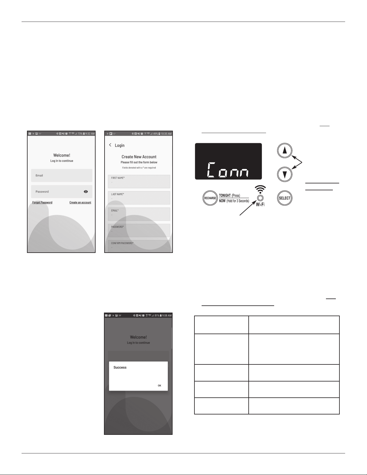
Step 2. Set Up Your Account
1. Activate the iQua™ app.
2. On the welcome screen, click Create an Account.
Step 3. Put Water Softener Control
into Connect Mode
1. If you haven’t already done so, program the water
softener with time, hardness, salt level, etc., as
s
hown on pages 14-16.
2. Make sure that the softener’s display shows the
current time, without the word “SET”. Press the
SELECT button several times if “SET” shows.
3. On the water softener’s front panel (see Fig. 31),
press both the
p
UP and
q
DOWN buttons, and
hold them for 3 seconds.
3. Fill in the required fields with your information
(name, phone number, address, etc.). Enter the e-
mail address you want to receive notifications.
Create a password to access your account.
4. Agree to the terms and press Complete.
5. A message to check
your e-mail appears.
An activation e-mail
has been sent to the
address you provided
when creating the
account. If you don’t
see it your inbox,
check your spam or
junk folders, and flag it
as safe so that future
notifications from
myiqua.com will not be
blocked. Wait to click
the link in this e-mail
until you have put the
water softener control
into Connect Mode, as
follows.
4. Release the buttons when “Conn” appears in the
display (See Fig. 31) and the connection status
light begins flashing amber.
5. The system is now in Connect Mode, ready to be
connected to the “cloud”, and will remain for 15
minutes. If Connect Mode has “timed out” and the
light is off, you can enter Connect Mode again by
pressing both the
p
UP and
q
DOWN buttons and
holding them for 3 seconds.
FIG. 29FIG. 28
Check your email to activate your
account
FIG. 30
FIG. 31
CONNECTION STATUS
light (see table below)
Press both
UP and
DOWN
buttons,
and hold for
3 seconds,
to put into
Connect Mode
Connection Status
light indication
Status
Flashing Amber
(for up to 15 min-
utes)
System is in Connect Mode,
waiting to be connected to the
“cloud” via the home’s wireless
router.
Green
System successfully connected
to the “cloud” and registered.
Red
System is currently receiving
an over-the-air update.
No light
System not currently connected
to the “cloud”.
6. With the system in the Connect Mode, follow the
instructions on the next page to use the app to
connect your water softener to the “cloud” via the
home’s wireless router.
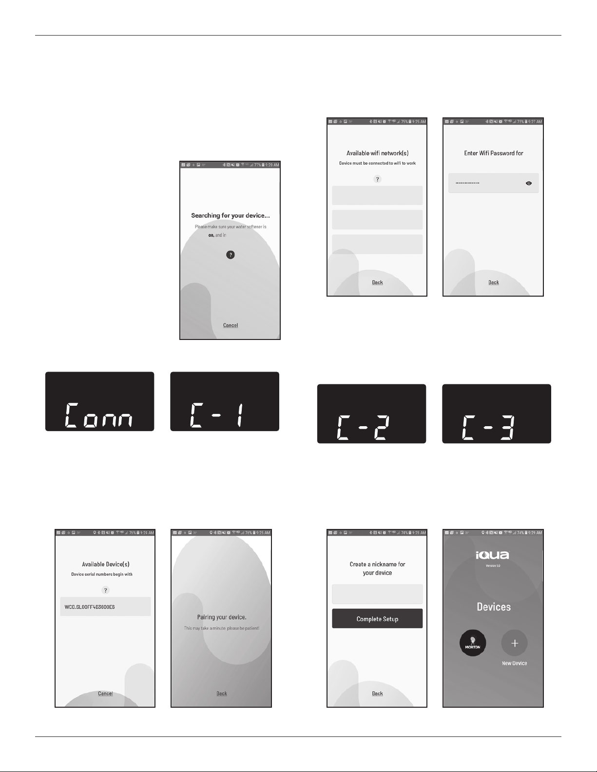
Step 4. Connect and Register Your
Water Softener
1. If you completed the steps on the previous page,
you will have received an account activation
e
-mail from myiqua.com. Open this e-mail and
click on the Activate Account link.
2. Sign in to your account
using the e-mail address
and password you pro-
vided when setting it up.
3. The app screen will
change to show
Searching for your
device...
4. Verify that the softener is
still in Connect Mode
(flashing amber light).
When the display on the
water softener changes
from “Conn” to “C-1”, it is
communicating with your
phone.
18 Morton
®
Water Softener Installation & Operation Manual
Connecting the System to Wi-Fi
FIG. 33
FIG. 34
5. The app screen will change to show a list of
devices in range. There should be a name that
begins with WCD, followed by a serial number.
This is your Morton water softener. Select it and
the screen changes to Pairing Your Device.
6. The app screen will change to show a list of wire-
less networks in range. Select your home’s wi-fi
router and enter your wi-fi network password.
7. The water softener’s display will change to “C-2”
when the system connects with the home’s wire-
less network. It will change again to “C-3” when it
connects with the iQua™ server in the “cloud”.
FIG. 36FIG. 35
FIG. 39
FIG. 40
8. The app will prompt you to provide a nickname for
your softener. This will be displayed on the
“Devices” list when you sign in to the app. After
entering the nickname, press Complete Setup.
WCD
connect mode
FIG. 32
FIG. 38FIG. 37
Home_Wireless_Network
H
om
e_W
i
rel
ess_N
et
w
ork
O
ther_Network_1
Other_Network_2
FIG. 42FIG. 41
My Softener
My Softener
Morton
®
Water Softener Installation & Operation Manual 19
Optional Settings:
= Salt Efficiency
= Clean Feature
= Clean Feature Minutes
= Maximum Days Between
Regenerations
= 97% Feature
= 12 / 24 Hour Clock
= Backwash & Fast Rinse Times
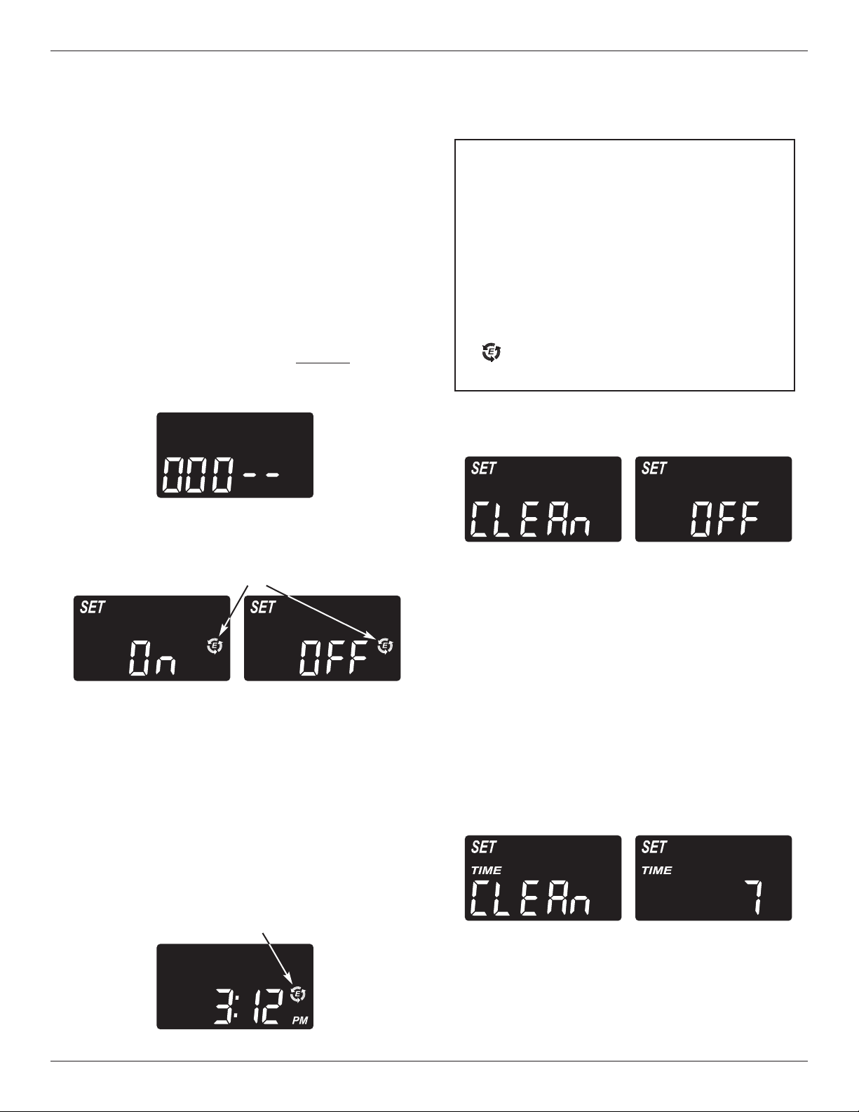
1. To set any of these options, press and hold the
SELECT button for 3 seconds until “000” shows in
the display.
Controller Features
FIG. 43
FIG. 44
Efficiency Icon
Then press (do not hold) SELECT again to display
one of the “Salt Efficiency” screens shown below.
Salt Efficiency: When this feature is ON, the
water softener will operate at salt efficiencies of
4000 grains of hardness per pound of salt or high-
er. The softener may recharge more often using
smaller salt dosage and less water. This softener
is shipped with the efficiency feature set OFF. Use
the
p
UP or
q
DOWN buttons to change between
OFF and ON. An efficiency icon will be displayed
when this feature is ON.
FIG. 45
Displayed when efficiency
is set to “ON”
2. Press SELECT again to display the “Set Clean”
screen.
Clean: This feature is beneficial on water sup-
plies containing iron and/or high amounts of sedi-
ments (sand, silt, dirt, etc.). When set to ON, a
backwash and fast rinse cycle will occur first, pre-
ceding the normal regeneration sequence. This
provides extra cleaning of the resin bed before it is
regenerated with the salt brine. To conserve water,
if your water supply does not contain iron or sedi-
ments, be sure this feature is set to OFF. The
default is OFF. Use the
p
UP or
q
DOWN buttons
to change between OFF and ON.
3. Press SELECT again to display the “Set Clean
Time” screen.
California Efficiency Requirement
Your Morton
®
Water Softener has a “High
Efficiency” feature with an ON or OFF setting.
This softener setting is shipped in the OFF posi-
tion, which utilizes the maximum rated capacity
while most often achieving maximum salt effi-
ciencies. When installing this unit in the State of
California, you MUST turn this setting to the ON
position, which may initiate more frequent
recharges. However it will operate at 4000
grains per pound of salt or higher.
If you wish to turn the Salt Efficiency feature ON
( icon will show in the display), follow the
instructions on this page.
FIG. 46
FIG. 47
Clean Feature Minutes: If you have set the
Clean Feature ON, the length of the extra back-
wash cycle auto matically is set to 7 minutes.
continued on next page
20 Morton
®
Water Softener Installation & Operation Manual
Controller Features
However, you can ad just this time from 1 to 30
minutes in length. To change this cycle time, use
t
he
p
U
P button to increase the time, or the
q
DOWN button to shorten the time. If no change
is desired, continue to next step.
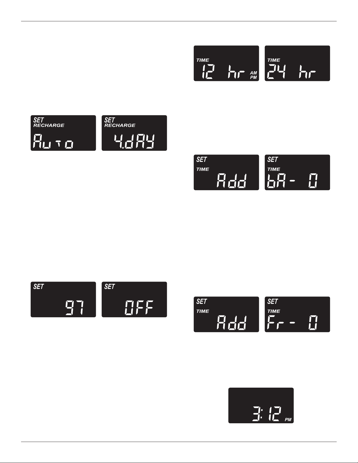
4. Press SELECT again to display the “Recharge
Days” screen.
continued from previous page
Maximum Days Between Regener -
ations: The electronic controller automatically
determines regeneration fre quency. This provides
the greatest operating efficiency and, under most
conditions this feature will be left in its default
mode. However, you can set this feature to force a
regeneration every set number of days. You may
want to do this if, for exam ple, your water supply
contains iron and you want the softener to regener-
ate at least once every few days to keep the resin
bed clean. Use the
p
UP or
q
DOWN buttons to
change the number of days (up to 15). If no
change is desired, continue to next step.
5. Press SELECT again to display the “97%” screen.
97% Feature: The 97% Feature can save salt
and water by regenerating when 97% of the soften-
er’s capacity has been used up. With this feature
ON, the regeneration can occur at any time (when-
ever the system has reached 97% of its capacity).
The default is OFF. If this feature is desired, turn it
on by pressing the
p
UP button.
6. Press SELECT again to display the “12 or 24 hr”
screen.
Backwash & Fast Rinse Times: If you
experience salty tasting water after regeneration,
you may need to increase the backwash and fast
rinse times. The cycle times during regeneration
are determined by the softener’s electronic con-
troller. However, you may increase the backwash
and fast rinse times, in 1 minute increments.
If you wish to increase the backwash time, use the
p
UP or
q
DOWN buttons to add up to 15 minutes.
Then press SELECT to display the fast rinse time
“Add” screen.
FIG. 49
12 or 24 Hour Clock: All time displays are
shown in 12 hour (AM/PM) time format at the
default setting. If 24 hour time format is de sired,
set to 24 hr by pressing the
p
UP button.
7. Press SELECT again to display the backwash time
“Add” screen.
FIG. 50
FIG. 48
If you wish to increase the fast rinse time, use the
p
UP or
q
DOWN buttons to add up to 15 minutes.
8. Press SELECT to return to the normal run (time of
day) screen.
FIG. 53
FIG. 51
FIG. 52
Controller Features
Cleansing Feature
The cleansing feature keeps larger particles of sedi-
m
ent from entering the home’s plumbing system. As
water passes through the softener, the larger sedi-
m
ent particles are collected in the integrated basket
and then rinsed to the drain before each regenera-
tion. The cleansing feature provides added protection
for water using appliances by reducing the chance of
larger particles entering the various products valves
and screens. The “Clean Feature” may be turned ON
to provide an extra backwash that will help keep the
cleansing screen clean. The default is OFF.
IMPORTANT: The cleansing feature is not intended to
replace pretreatment filtration. For
problem water applications, additional
sediment filtration is recommended.
Top
Distributor
Cleansing Screen
Resin
Tank
FIG. 54
Morton
®
Water Softener Installation & Operation Manual 21
Power Outage Memory
I
f electrical power to the softener is interrupted, the
time display is blank, but the electronic controller
keeps correct time for several hours. When power is
restored, you must reset the present time only if the
display is flashing. All other settings are maintained
and never require resetting unless a change is
desired. If the time is flashing after a long power out-
age, the softener continues to work as it should to
provide you with soft water. However, regenerations
may occur at the wrong time of day until you reset the
clock to the correct time of day.
NOTE: If the water softener was regenerating when
power was lost, it will now finish the cycle.
Vacation Note
Morton demand controlled water softeners regenerate
only while water is being used and softening capacity
must be restored. For this reason, the unit will not
regenerate when you are away from home for extend-
ed periods.
22 Morton
®
Water Softener Installation & Operation Manual
Routine Maintenance
Refilling with Salt
Lift the salt lid and check the salt storage level fre-
quently. If the water softener uses all the Morton
®
C
lean and Protect
™
o
r Clean and Protect
™
P
lus Rust
D
efense
™
P
ellets before you refill it, you will experi-
ence hard water. Until you have established a refill-
ing routine, check the salt every two or three weeks.
Always add if less than 1/4 full. Be sure the brinewell
cover is on.
NOTE: In humid areas, it is best to keep the salt stor-
age level lower, and to refill more often to
avoid salt “bridging”.
Recommended Salt: We recommend using
Morton
®
Clean and Protect
™
or Clean and Protect
™
Plus Rust Defense
™
Pellets in the familiar yellow bag.
For soft water, nothing works harder. Guaranteed
®
.
Salt Not Recommended: Rock salt, high in impu-
rities, block, granulated, table, ice melting, ice cream
making salts, etc., are not recommended.
Salt with Iron Removing Additives: Some salts
have an additive to help a water conditioner handle
iron in a water supply. For this we recommend
Morton
®
Rust Remover Super Pellets
®
in the green
bag.
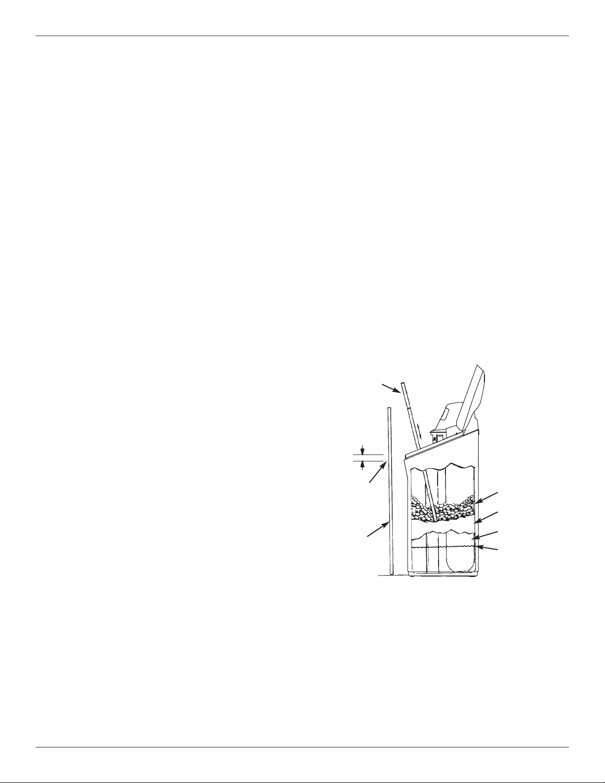
Breaking a Salt Bridge
S
ometimes, a hard crust or salt “bridge” forms in the
brine tank. It is usually caused by high humidity or
the wrong kind of salt. When the salt “bridges,” an
empty space forms between the water and the salt.
Then, salt will not dissolve in the water to make brine.
Without brine, the resin bed is not recharged and
hard water will result.
If the storage tank is full of salt, it is difficult to tell if
you have a salt bridge. A bridge may be underneath
loose salt. Take a broom handle, or like tool, and
hold it next to the water softener. Measure the dis-
tance from the floor to the rim of the water softener.
Then, carefully push the broom handle straight down
into the salt. If a hard object is felt before the pencil
mark is even with the top, it is most likely a salt
bridge. Carefully push into the bridge in several
places to break it. Do not use any sharp or pointed
objects as you may puncture the brine tank. Do not
try to break the salt bridge by pounding on the out-
side of the salt tank. You may damage the tank.
FIG. 55
Salt Bridge
Salt
Empty Space
Water Level
1” - 2”
Pencil
Mark
Broom
Handle
Push tool into
salt bridge to
break
Questions? Call Toll Free 1-888-64 WATER (1-888-649-2837)
or visit www.mortonwatersofteners.com
When you call, please be prepared to provide the model and serial number,
found on the rating decal, located on the rim below the salt lid hinges.
Morton
®
Water Softener Installation & Operation Manual 23
Routine Maintenance
Protect the Water Softener from
Freezing
If the softener is installed where it could freeze (sum-
mer cabin, lake home, etc.), you must drain all water
from it to stop possible freeze damage. To drain the
softener:
1. Close the shut-off valve on the house main water
pipe, near the water meter or pressure tank.
2. Open a faucet in the soft water pipes to vent pres-
sure in the softener.
3. Move the stem in the single bypass valve to bypass.
Close the inlet and outlet valve in a 3 valve bypass
system, and open the bypass valve. If you want
water in the house pipes again, reopen the shut-off
valve on the main water pipe.
4. Unplug the power supply at the wall outlet. Remove
the softener’s top cover, together with the salt lid.
Take off both drain hoses if they will interfere with
moving the softener into position over the drain.
5. Push the bypass valve body toward the softener (as
shown in Figure 15) and carefully remove the large
holding clips at the softener inlet and outlet.
Separate the softener from the plastic installation
adaptors, or from the bypass valve.
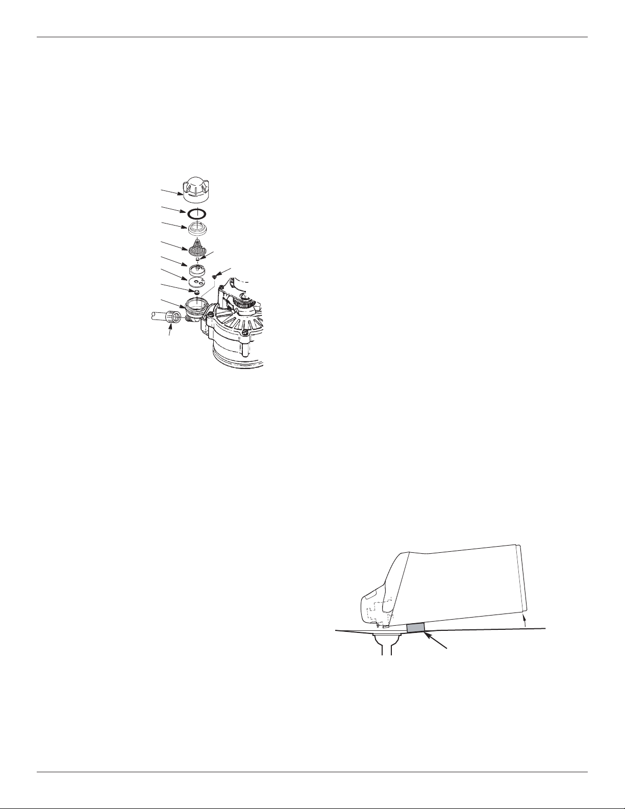
6. Lay a piece of 2 inch thick board near the floor drain
(See Figure 57).
7. Move the softener close to the drain. Slowly and
gently, tip it over until the rim rests on the wood
block with the inlet and outlet over the drain. Do not
allow the softener’s weight to rest on the inlet and
outlet fittings or they may break.
8. Tip the bottom of the softener up a few inches and
hold until all water has drained. Leave the softener
laying like this until you are ready to use it. Plug the
inlet and outlet with clean rags to keep dirt, bugs,
etc. out.
Floor Drain
FIG. 57
Wood Block
FIG. 56
Cap
O-ring Seal
Screen Support
Screen
Gasket
*Flow Plug (HVDC)
Housing
Ferrule
Nut
Cone Screen
*Flow Plug
*Install with lettered
side up, concave
side down.
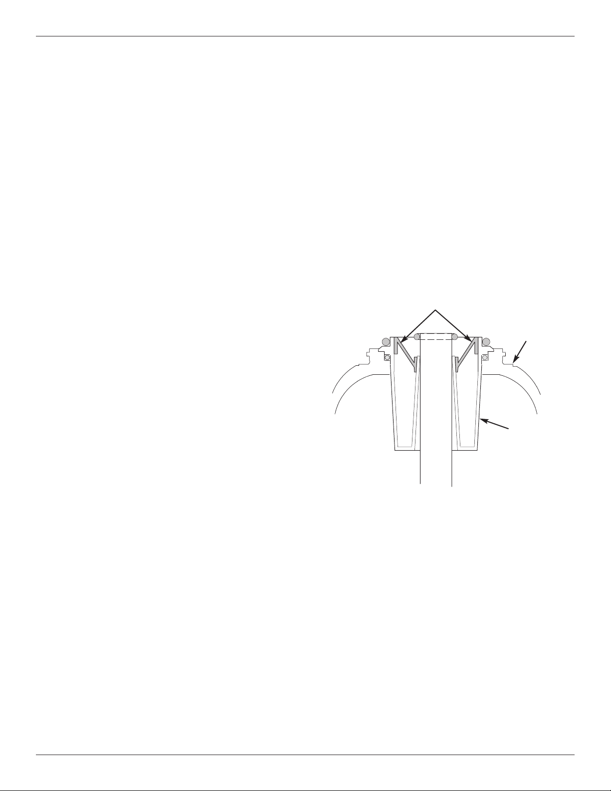
Cleaning the Nozzle & Venturi
A clean nozzle & venturi (See Figure 56) is a necessity
f
or the water softener to work properly. This small
component creates the suction to move brine from the
brine tank, into the resin tank. If it should become
plugged with sand, silt, dirt, etc., the water softener will
not work, and hard water will result.
Nozzle & Venturi Disc
IMPORTANT: Be sure small hole in the gasket is cen-
tered directly over the small hole in the nozzle & ven-
turi housing. Be sure the numbers are facing up.
To get access to the nozzle & venturi, remove the
water softener’s top cover. Put the bypass valve(s)
into the bypass position. Be sure the water softener is
in soft water (service) cycle (no water pressure at noz-
zle & venturi). Then, holding the nozzle & venturi
housing with one hand, un screw the cap. Do not lose
the o-ring seal. Lift out the screen support and screen.
Then, remove the nozzle & venturi disc, gasket and
flow plug(s). Wash the parts in warm, soapy water
and rinse in fresh water. Be sure to clean both the top
and bottom of the nozzle & venturi disc. If needed,
use a small brush to remove iron or dirt. Do not
scratch, misshape, etc., surfaces of the nozzle & ven-
turi.
Carefully replace all parts in the correct order.
Lubricate the o-ring seal with silicone grease and
locate in place. Install and tighten the cap by hand,
while supporting the housing. Overtightening may
break the cap or housing. Put the bypass valve(s) into
service (soft water) position.
Recharge the softener to reduce water level in the
tank. This will also assure that the softener is com-
pletely recharged and ready to provide softened water
again. Check the water level in the tank by looking
down the brinewell. If the water level does not drop
after a recharge, the problem has not been resolved.
Call 1-888-64 WATER or visit www.mortonwatersoften-
ers.com.
24 Morton
®
Water Softener Installation & Operation Manual
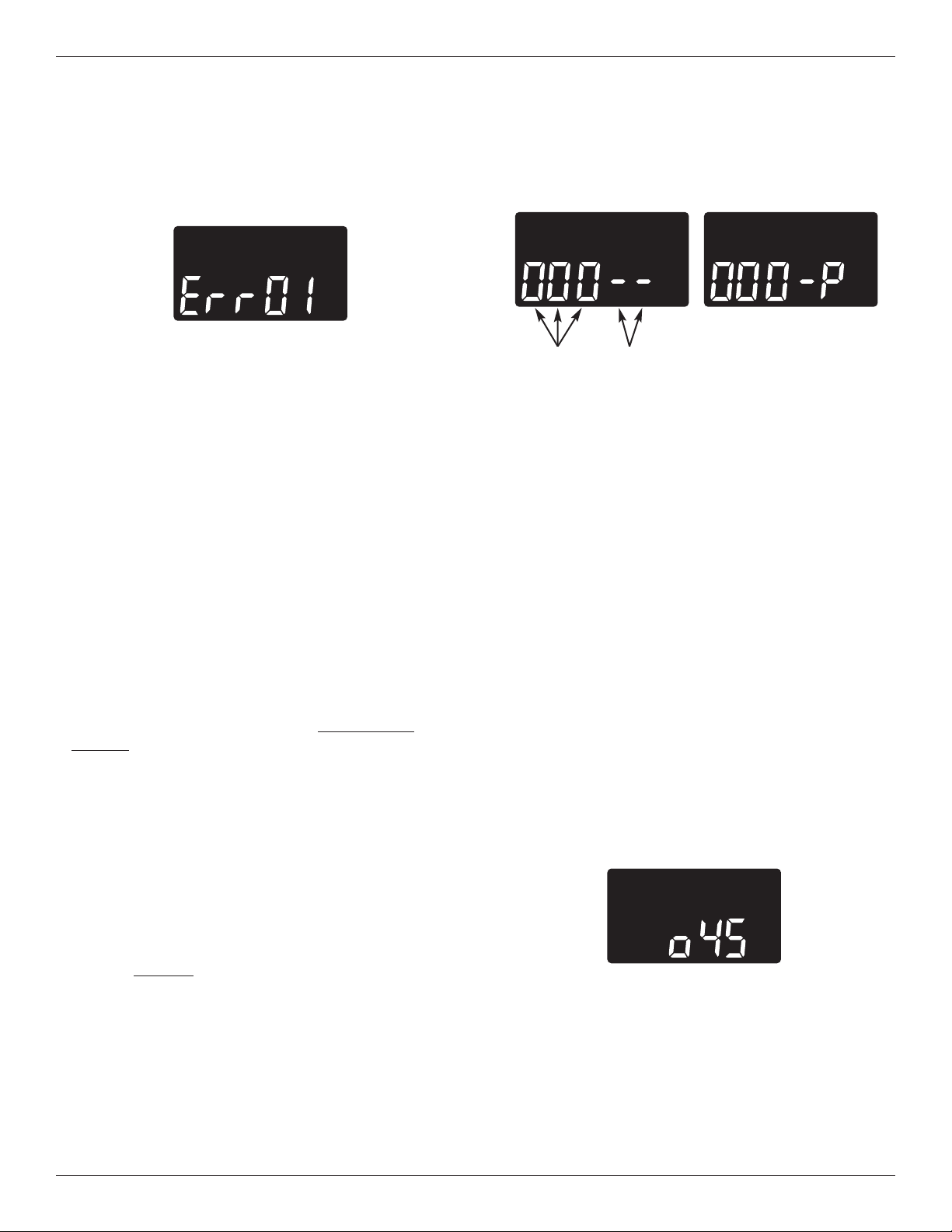
Error Codes 01, 02, 03, 04 & 05:
These are the water softener error codes unrelated to
the optional water shutoff valve. While one is in the
display, the SELECT button remains operational so
the service person can perform the Manual Advance
Diagnostics, below, to further isolate the problem.
Procedure for removing error codes 01 through 05
from display:
1. Unplug power supply from electrical outlet.
2. Correct problem.
3. Plug power supply back in.
4. Wait 8 minutes. The error code will return if
the problem was not corrected.
Error Codes 07, 08 & 09:
These error codes indicate a problem with the option-
al water shutoff valve. Make sure that the water shut-
off valve is still plugged into the water softener’s con-
trol board. To clear one of these codes from the dis-
play, press the RECHARGE button and hold for 3
seconds. If the error code is displayed again after a
minute or two, the water shutoff valve probably needs
to be replaced.
Manual Advance Diagnostics
Use the following procedures to advance the water
softener through the regeneration cycles to check
operation.
Remove the top cover to expose the valve and ob -
serve cam and switch operation during valve rotation.
1. Press and hold
SELECT for 3 seconds until “000”
shows in the display, then release.
2. The 3 digits indicate water meter operation:
000 (steady) = Soft water not in use, and no flow
through the meter.
Open a nearby soft water faucet.
000 to 140 (continual) = Repeats for each gallon
of water passing through
the meter.
4. Use the RECHARGE button to manually advance
the valve into each cycle and check correct switch
operation.
NOTE: Be sure water is in contact with the salt, and
not separated by a salt bridge (See "Breaking
A Salt Bridge" section).
5. While in this diagnostic screen, the following infor-
mation is available and may be beneficial for vari-
ous reasons. This information is retained by the
computer from the first time electrical power is
applied to the electronic controller.
a. Press the
p
UP button to display the number of
days this electronic control has had electrical
power applied.
b. Press the
q
DOWN button to display the number
of regenerations initiated by this electronic con-
trol since the code number was entered.
6. Press and hold the SELECT button until the model
code (o45) shows in the display. This code identi-
fies the softener model. If an incorrect model code
is displayed, the softener will operate on incorrect
configuration data.
7. To change the code number, press the
p
UP or
q
DOWN button until the correct code shows.
8. To return to the present time display, press the
SELECT button.
Water
Meter
Switch
Automatic Electronic Diagnostics
T
his water softener self-monitors electronic compo-
nents and circuits for correct operation. If a malfunc-
tion occurs, an error code appears in the display.
FIG. 58
FIG. 59
3
. The letter “P” and a dash (or dashes) indicate
POSITION switch operation (See Figure 59). If the
l
etter appears, the switch is closed. If the dash
shows, the switch is open.
Troubleshooting
FIG. 60
Morton
®
Water Softener Installation & Operation Manual 25
Troubleshooting
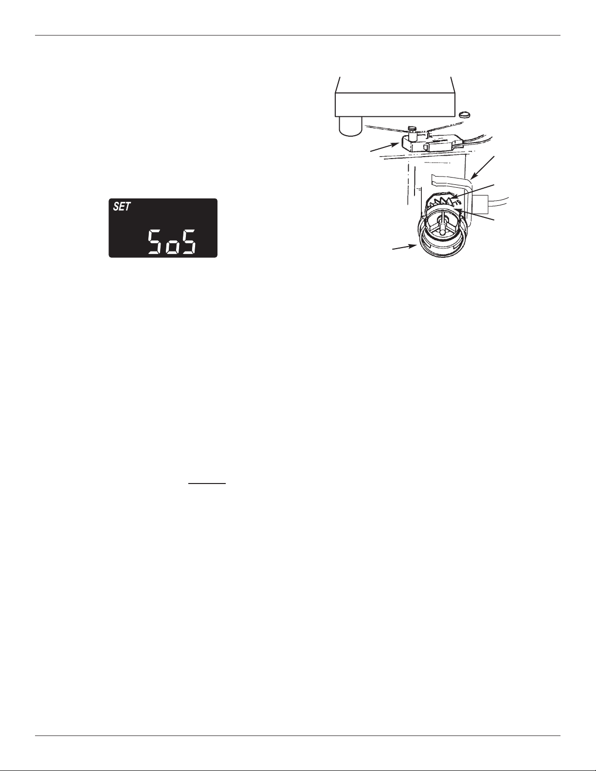
Resetting to Factory Defaults
T
o reset the electronic controller to its factory default
for all settings (time, hardness, etc.):
1. Press the SELECT button and hold it until the dis-
p
lay changes twice to show “CODE” and the flash-
ing model code.
2. Press the
p
UP button (a few times, if necessary)
to display a flashing “SoS”.
3. Press the SELECT button, and the electronic con-
troller will restart.
4. Set the present time, hardness, etc., as described
on pages 14-16.
This check verifies proper operation of the valve
motor, brine tank fill, brine draw, regeneration flow
rates, and other controller functions. Always make
the initial checks, and the manual initiated diagnos-
tics.
NOTE: The electronic control display must show a
steady time (not flashing). If an error code
shows, first press the SELECT button to enter
the diagnostic display.
1. Press the RECHARGE button and hold in for 3
seconds. RECHARGE begins to flash as the soft-
ener’s valve advances from the service to fill posi-
tion. Remove the brinewell cover and, using a
flashlight, observe fill water entering the tank.
If water does not enter the tank, look for an
obstructed nozzle, venturi, fill flow plug, brine tub-
ing, or brine valve riser pipe.
2. After observing fill, press the RECHARGE button to
move the softener’s valve into the brine position. A
slow flow of water to the drain will begin. Verify
brine draw from the brine tank by shining a flash-
light into the brinewell and observing a noticeable
drop in the liquid level. This may take 15 to 20
minutes.
Manual Advance Regeneration Check
NOTE: Be sure water is in contact with the salt, and
not separated by a salt bridge (See "Breaking
A Salt Bridge" section).
If the water softener does not draw brine, check for
(most likely to least likely):
= Dirty or plugged nozzle and venturi, see
"Cleaning the Nozzle and Venturi" section.
= Nozzle and venturi not seated on the gasket, or
gasket deformed.
= Valve seals leaking.
= Restriction in valve drain, causing a back-pres-
sure (bends, kinks, elevated too high, etc.). See
"Install Valve Drain Hose" section.
= Obstruction in brine valve or brine tubing.
NOTE: If water system pressure is low, an elevated
drain hose may cause back pressure, stop-
ping brine draw.
3. Press the RECHARGE button to move the soften-
er’s valve into the backwash position. Look for a
fast flow of water from the drain hose. Check that
the drain can adequately handle the flow and vol-
ume.
An obstructed flow indicates a plugged top distribu-
tor, backwash flow plug, or drain hose.
4. Press the RECHARGE button to move the soften-
er’s valve into the fast rinse position. Again look
for a fast drain flow. Allow the softener to rinse for
a few minutes to flush out any brine that may
remain in the resin tank from the brining cycle test.
5. To return the softener’s valve to the service posi-
tion, press the RECHARGE button.
FIG. 61
Motor
Turbine
Support
& Shaft
Sensor
Housing
Turbine
Valve Outlet
Position
Switch
FIG. 62
26 Morton
®
Water Softener Installation & Operation Manual
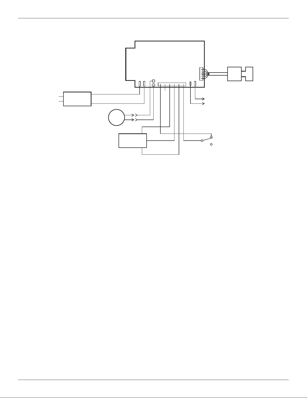
Wiring Schematic
FIG. 63
Need help troubleshooting? Call Toll Free 1-888-64 WATER (1-888-649-2837)
or visit www.mortonwatersofteners.com
When you call, please be prepared to provide the model and serial number,
found on the rating decal, located on the rim below the salt lid hinges.
N
O
Valve
Motor
Position
Switch
N
C
Pwr.
In
Position/
Turbine
Motor
24V DC
Auxiliary Output
J6
24V DC
120V AC
60 Hz
Power
Supply
C
org
grn
OUT
+5
GND
Turbine
Sensor
B
ack of Electronic
Controller (PWA)
Optional
Motorized Water
Shutoff Valve
Morton
®
Water Softener Installation & Operation Manual 27
The Motorized Water Shutoff Valve (sold separately)
may be used with this Morton
®
Wi-Fi connected water
softener and the iQua™ app to remotely turn off the
home’s water supply. For example, you may want to
t
urn off the water when going away on vacation.
Install the motorized shutoff valve in the plumbing,
upstream of the softener (see page 10), and plug the
cable into the softener’s electronic control board with
the power off (see page 10 and Figure 63).
On the iQua™ app, near the bottom of the softener’s
main dashboard, there is a line labeled “Water
Control” with a button that, when pressed, alternates
between “Water On” and “Water Off”. If you receive
an alert indicating continuous water flow, you can use
this control to remotely shut off the water.
The system default for triggering a continuous water
flow alert is 20 minutes of flow at 0.4 gallons per
minute or higher. The time and water flow trigger val-
ues may also be adjusted in the “Alerts” section.
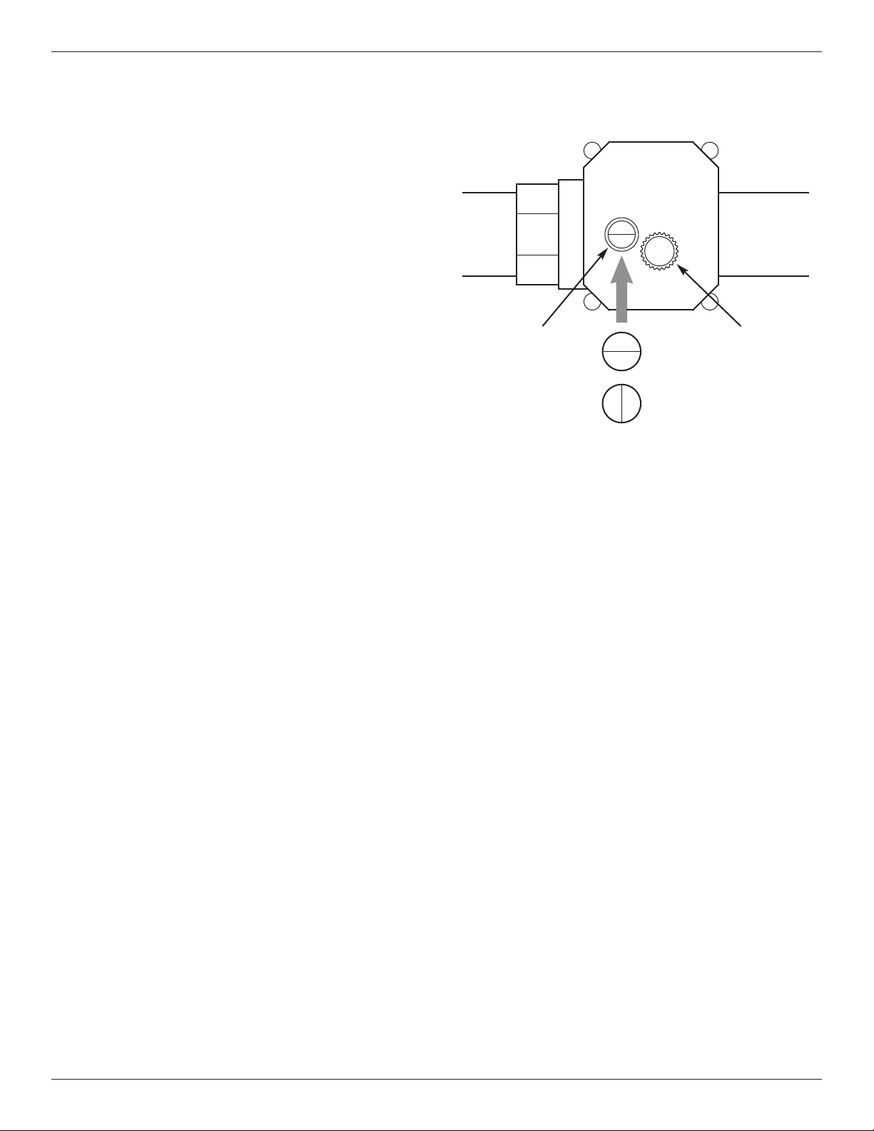
To manually operate the motorized water shutoff
valve, pull out the round knob on the valve and turn it
until the red line in the sight glass matches the
desired (open or closed) position. See Figure 64. If
you manually operate the valve, the app’s “Water
Control” feature will be disabled until you reset it by
clicking “Yes” next to the “Regain Control?” prompt.
OPEN
Motorized Water Shutoff Valve
Knob -
pull out
to turn
OPEN
CLOSED
Sight
glass
FIG. 64
Optional Motorized Water Shutoff Valve
28 Morton
®
Water Softener Installation & Operation Manual
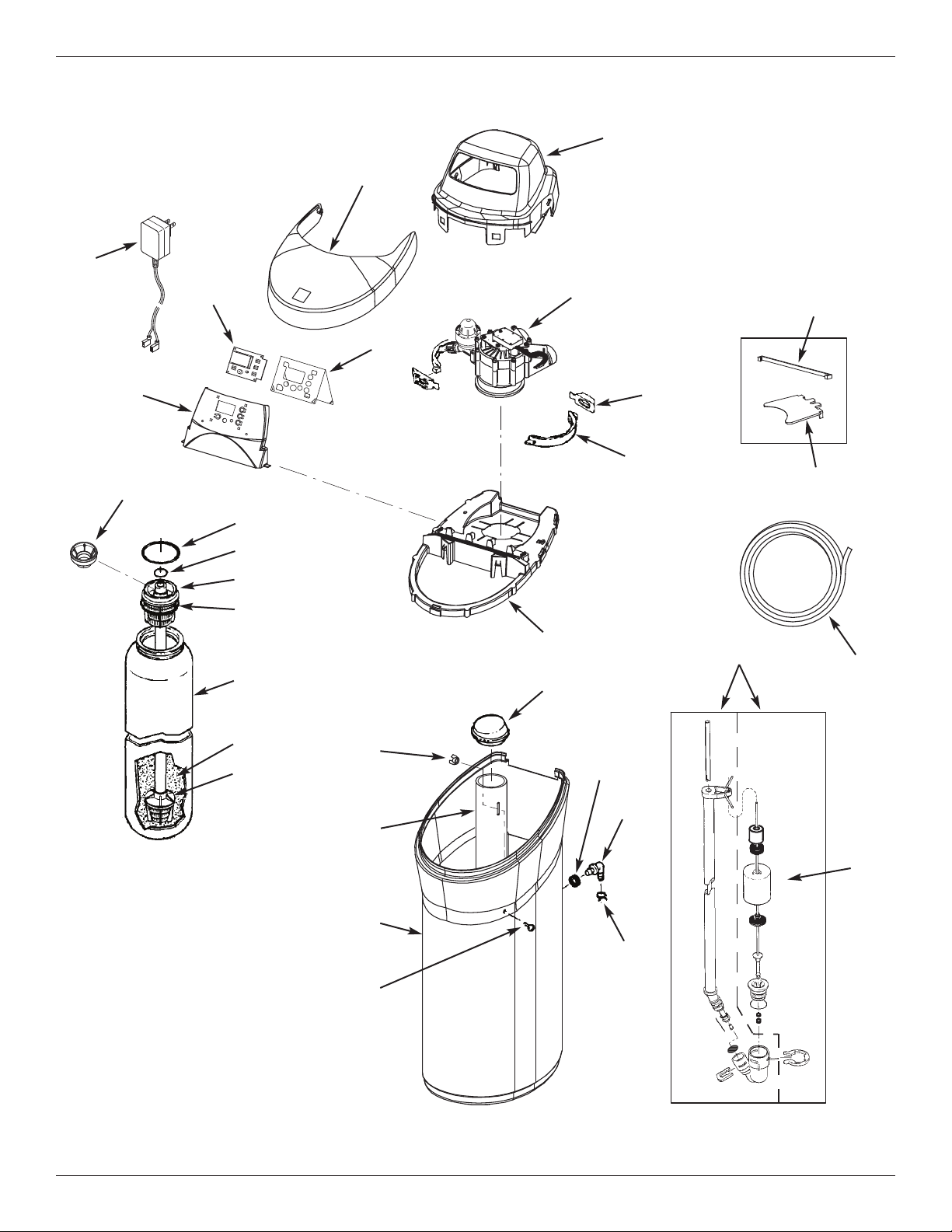
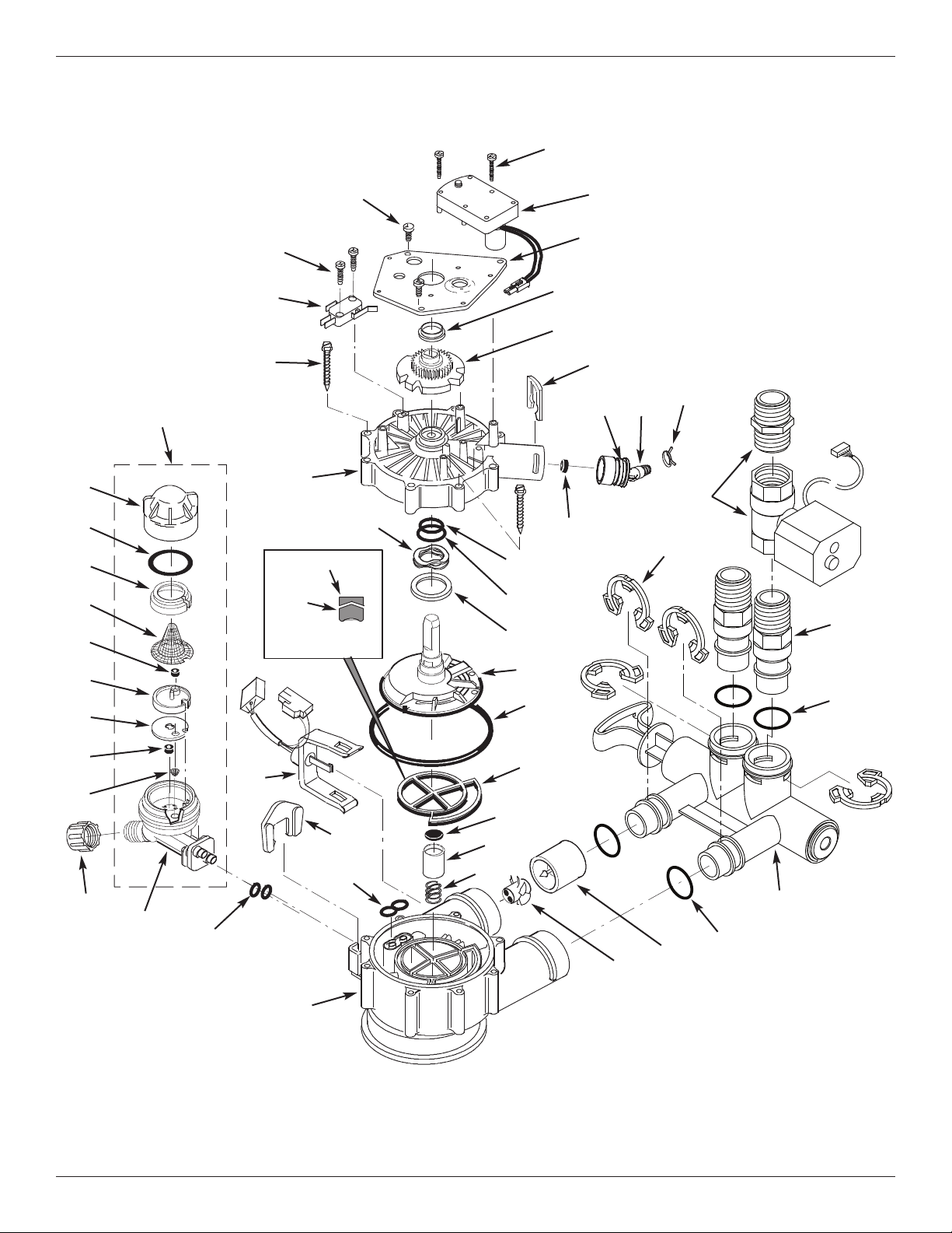
Softener Exploded View
8
7
6
5
1
2
3
4
Valve Assembly
See Pages 30 & 31
for parts
29
30
28
24
25
6
7
8
9
11
10
12
13
14
15
16
17
18
22
23
26
27
19
20
21
5
Morton
®
Water Softener Installation & Operation Manual 29
Softener Parts List
Key
No.
Part No. Description
1 7
329803
T
op Cover
2 7381504
R
epl. Salt Lid (includes instruction
decal & Morton badge)
3 7351054 Power Supply, 24V DC
4 7381300
Repl. Electronic Control Board
(PWA)
5 7382403 Heat Shield
6 7372741 Faceplate (order decal below)
¢
7381245 Faceplate Decal
7 7265025 Filter Screen
– 7112963
Distributor O-Ring Kit
(includes Key Nos. 8-10)
8
á
O-Ring, 2-7/8” x 3-1/4”
9
á
O-Ring, 13/16” x 1-1/16”
10
á
O-Ring, 2-3/4” x 3”
11 7077870 Top Distributor
12 7247996 Repl. Resin Tank, 10” x 40”
13 0502272 Resin, 1 cu. ft.
14 7105047 Repl. Bottom Distributor
15 7338365 Repl. Brine Tank
Key
No.
Part No. Description
– 7327576
Brinewell Mounting Hardware Kit
(includes Key Nos. 16 & 17)
16
á
Screw, 1/4-20 x 5/8”
17
á
Wing Nut, 1/4-20
18 7214375
Brinewell Assembly
(including salt level decal)
– 7331258
Overflow Hose Adaptor Kit
(includes Key Nos. 19-21)
19
á
Adaptor Elbow
20
á
Grommet
21
á
Hose Clamp
22 7155115 Cover, Brinewell
23 7325396 Rim
– 7331177
Tank Neck Clamp Kit
(includes Key Nos. 24 & 25)
24
á
Clamp Section (2 req.)
25
á
Retainer Clip (2 req.)
26 7310202 Brine Valve Assembly
27 7327568 Float, Stem & Guide Assembly
28 7139999 Drain Hose
29 – Cover Lock (for shipping only)
30 – Rim Insert (for shipping only)
¢
7381229 Owner’s Manual
¢ Not illustrated.
Questions? Call Toll Free 1-888-64 WATER (1-888-649-2837)
or visit www.mortonwatersofteners.com
When you call, please be prepared to provide the model and serial number,
found on the rating decal, located on the rim below the salt lid hinges.
To order repair parts call toll free 1-888-649-2837.
Manufactured and warranted by
Water Channel Partners
1890 Woodlane Drive
Woodbury, MN 55125
30 Morton
®
Water Softener Installation & Operation Manual
109
102
104
146
147
144
145
127
132
134
135
137
138
139
140
141
142
130
133
131
116
128
129
103
105
106
111
121
122
123
124
123
126
125
143
112
117
113
115
119
120
136
Wear Strip
Seal
Cross-section
View
100
101
110
108
107
118
114
148
Valve Exploded View
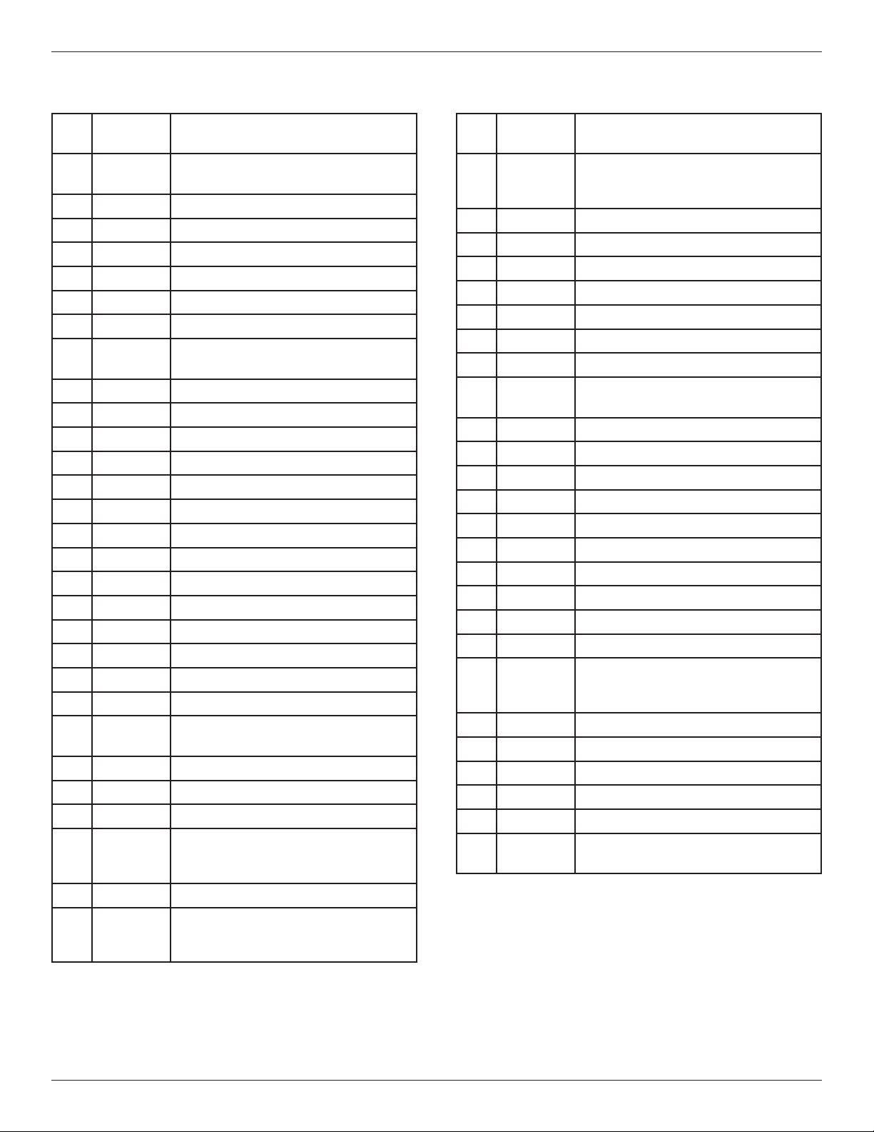
Morton
®
Water Softener Installation & Operation Manual 31
Valve Parts List
K
ey
No.
Part No. Description
– 7384691
M
otor, Cam & Gear Kit, 1”
(includes Key Nos. 100-102)
100
á
Motor
101
á
Cam & Gear
102 7224087 Screw, #8-32 x 1” (2 req.)
103 7231393 Motor Plate
104 0900857 Screw, #6-20 x 3/8” (3 req.)
105 7171250 Bearing
– 7331169
Drain Hose Adaptor Kit
(includes Key Nos. 106-110)
106
á
Clip, Drain
107
á
Hose Clamp
108
á
Drain Hose Adaptor
109
á
O-Ring, 15/16” x 1-3/16”
110
á
Flow Plug, 2.0 gpm
– 7185487 Seal Kit (includes Key Nos. 111-116)
111
á
O-Ring, 5/8” x 13/16”
112
á
O-Ring, 1-1/8” x 1-1/2”
113
á
O-Ring, 4-1/2” x 4-7/8”
114
á
Rotor Seal
115
á
Seal
116
á
Seal, Nozzle & Venturi
117 7174313 Bearing, Wave Washer
118 7185500 Rotor & Disc
– 7342712
Drain Plug Kit, 1”
(includes Key Nos. 115, 119 & 120)
119
á
Plug, Drain Seal
120
á
Spring
121 7337589 Clip, 1”, pack of 4
122 7342704
Installation Adaptor, 1”, pack of 2,
including 2 ea. Clips & O-Rings
(See Key Nos. 121 & 123)
123 7337597 O-Ring, 1-1/16” x 1-5/16”, pack of 4
124 7214383
Bypass Valve Assembly, 1”,
including 2 ea. Clips & O-Rings
(See Key Nos. 121 & 123)
K
ey
No.
Part No. Description
– 7
290931
Turbine & Support Assembly,
i
ncluding 2 O-Rings (See Key No.
123) & 1 ea. of Key Nos. 125 & 126
125
á
Turbine Support & Shaft
126
á
Turbine
127 7309811 Wire Harness, Sensor
128 7081201 Retainer, Nozzle & Venturi
129 7171145 Valve Body
130 7342649 O-Ring, 1/4” x 3/8”, pack of 2
131 1202600 Nut - Ferrule
132 7257454
Nozzle & Venturi Assembly
(incl. Key Nos. 128, 130 & 133-142)
133
á
Housing, Nozzle & Venturi
134
á
Cone Screen
135
á
Fill Flow Plug, 0.3 gpm
136
á
Gasket
137
á
Nozzle & Venturi Disc, Blue
138
á
Flow Plug, 0.15 gpm
139
á
Screen
140
á
Screen Support
141
á
O-Ring, 1-1/8” x 1-3/8”
142
á
Cap
¢
7298913
Repl. Nozzle, Venturi & Gasket Kit
(includes Key Nos. 130, 134, 136,
137 & 141)
143 7175199 Wave Washer
144 7171161 Valve Cover
145 7342681 Screw, #10 x 2-5/8”, pack of 8
146 7305150 Switch
147 7140738 Screw, #4-24 x 3/4” (2 req.)
148 7379785
Motorized Water Shutoff Valve,
including 1” NPT Nipple Ù
Questions? Call Toll Free 1-888-64 WATER (1-888-649-2837)
or visit www.mortonwatersofteners.com
When you call, please be prepared to provide the model and serial number,
found on the rating decal, located on the rim below the salt lid hinges.
¢ Not illustrated
Ù Not included with softener

EXTEND YOUR WARRANTY:
Use Morton
®
MWSC Water Softener Cleanser
The factory warranty for your water softener is shown below. The one year warranty period, on all parts other than
the salt storage tank and fiberglass mineral tank, can be extended to five (5) years from the date of purchase if you
u
se Morton
®
M
WSC Water Softener Cleanser on your system. Use one bottle of Morton
®
M
WSC Water Softener
Cleanser, as directed, every four months from the date of purchase of the water softener. Retain proof of purchase
of Morton
®
MWSC Water Softener Cleanser to validate any warranty claim after the first year. Use of any water
softener additive other than Morton
®
MWSC will invalidate any extended warranty coverage.
WATER SOFTENER LIMITED WARRANTY - MODEL M45C
Warrantor guarantees, to the original owner, that:
One Year Full Warranty:
● For a period of one (1) year from the date of purchase, all parts will be free from defects in materials and
workmanship and will perform their normal functions.
● For a period of one (1) year from the date of purchase, labor to repair or replace any part deemed to be
defective in materials or workmanship, will be provided at no additional cost.
Limited Warranties:
● For a period of ten (10) years from the date of purchase, the salt storage tank and fiberglass mineral tank
will not rust, corrode, leak, burst, or in any other manner, fail to perform its proper functions.
● For a period of three (3) years from the date of purchase, the electronic control board will be free of
defects in materials and workmanship and will perform its normal functions.
If, during such respective period, a part proves to be defective, Warrantor will ship a replacement part, directly
to your home, without charge. Labor necessary to maintain this product is not covered by the product warranty.
If you have questions regarding a Morton water softener or MWSC, need assistance with installation or trou-
bleshooting, wish to order a part or report a warranty issue, we are just a phone call away. Simply dial 1-888-
64WATER (1-888-649-2837) for assistance, or visit www.mortonwatersofteners.com.
This water softener is manufactured by Water Channel Partners, 1890 Woodlane Drive, Woodbury, MN 55125.
General Provisions
The warranty does not apply to any defect, malfunction or failure arising from, relating to or caused by: (i)
operation at water pressures which exceed 125 psi or at water temperatures which exceed 120°F; (ii) repairs
made by others than, or without the consent of, Warrantor or if the product has been subject to abuse, misuse,
neglect, tampering, accident or damage by circumstances beyond Warrantor’s control; (iii) products damaged
or abused in shipment without fault of Warrantor; (iv) non-residential installations; (v) defects or failures due to
misapplication, abuse, improper installation or abnormal conditions of temperature, humidity, abrasives, dirt or
corrosive matter; (vi) unusual force of nature such as, but not limited to, flood, hurricane, tornado or earth-
quake; and (vii) products which have been in any way tampered with, modified or altered.
The foregoing warranties do not cover and Warrantor shall not be responsible for reimbursement for labor,
transportation, removal, installation, or other expenses which may be incurred by Purchaser in connection with
replacement or repair or returning the product to Warrantor.
THERE ARE NO WARRANTIES ON THE WATER SOFTENER BEYOND THOSE SPECIFICALLY DESCRIBED
ABOVE. ALL IMPLIED WARRANTIES, INCLUDING, WITHOUT LIMITATION, ANY IMPLIED WARRANTY OF
MERCHANTABILITY OR OF FITNESS FOR A PARTICULAR PURPOSE ARE HEREBY DISCLAIMED. WAR-
RANTOR’S SOLE LIABILITY FOR ANY PRODUCT IS LIMITED TO THE REPAIR OR REPLACEMENT OF
SUCH PRODUCT, OR A REFUND OF THE PURCHASE PRICE ACTUALLY RECEIVED BY WARRANTOR
FOR SUCH PRODUCT, AT WARRANTOR’S SOLE DISCRETION. WARRANTOR WILL NOT BE LIABLE FOR
ANY INDIRECT, INCIDENTAL, SPECIAL, CONSEQUENTIAL OR PUNITIVE DAMAGES OF ANY KIND,
NATURE OR DESCRIPTION WHATSOEVER. NO WARRANTOR DEALER, AGENT, REPRESENTATIVE, OR
OTHER PERSON IS AUTHORIZED TO EXTEND, EXPAND OR MODIFY THE WARRANTIES EXPRESSLY
DESCRIBED ABOVE.
Some states do not allow limitations on how long an implied warranty lasts or exclusions or limitations of inci-
dental or consequential damage, so the limitations and exclusions in this warranty may not apply to you. This
warranty gives you specific legal rights, and you may have other rights which vary from state to state. This
warranty applies to consumer-owned installations only.
32 Morton
®
Water Softener Installation & Operation Manual