Loading ...
Loading ...
Loading ...
Page 18
P-164000734 Rev 01
4. Operation
Low-Battery Warning
• The and indicators solid.
• The audio alarm beeps every three seconds.
The remaining battery power is low. Shut down all applications on the connected equipment because
automatic UPS shutdown is imminent.
End of Battery Backup Time
• LCD displays "End of backup time".
• All the LEDs go OFF .
• The audio alarms stops.
4.5 Return of AC Input Power
Following an outage, the UPS restarts automatically when AC input power returns (unless the restart
function has been disabled) and the load is supplied again.
4.6 UPS Remote Control Functions
The 5P offers a choice between two remote control functions.
• RPO: Remote Power Off allows a remote contact to be used to disconnect all the equipment connected
to the UPS. Restarting the UPS requires manual intervention.
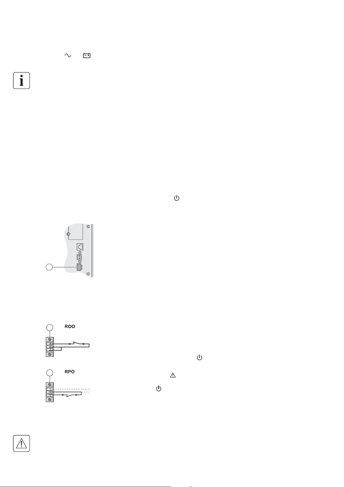
• ROO: Remote ON/OFF allows remote action of the
button to shut down the UPS.
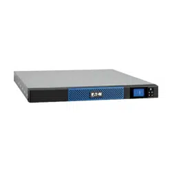
These functions are obtained by opening a contact connected between the appropriate pins of connector (4) on
the rear panel of the UPS (see fi gures below).
4
Remote Control Connection and Test
1. Check that the UPS is OFF and disconnected from the AC input source.
2. Remove connector (4).
3. Connect a normally closed volt-free contact (60 Vdc / 30 Vac max., 20 mA max., 0.75 mm
2
[18 AWG] cable
cross-section) between the two pins of connector (4) (see diagram).
4
Contact open: UPS shutdown
Contact closed: UPS start-up (UPS connected to AC power and AC power is available)
Note: The local ON/OFF control using the button overrides the remote-control function.
4
Contact open: UPS shutdown, indicator illuminates
To return to normal operation, deactivate the remote external contact and restart
the UPS by pressing the
button.
4. Plug connector (4) into the back of the UPS.
5. Connect and restart the UPS following the previously described procedures.
6. Activate the external remote shutdown contact to test the function.
Warning. This connector must only be connected to SELV (Safety Extra-Low Voltage) circuits.
Loading ...
Loading ...
Loading ...