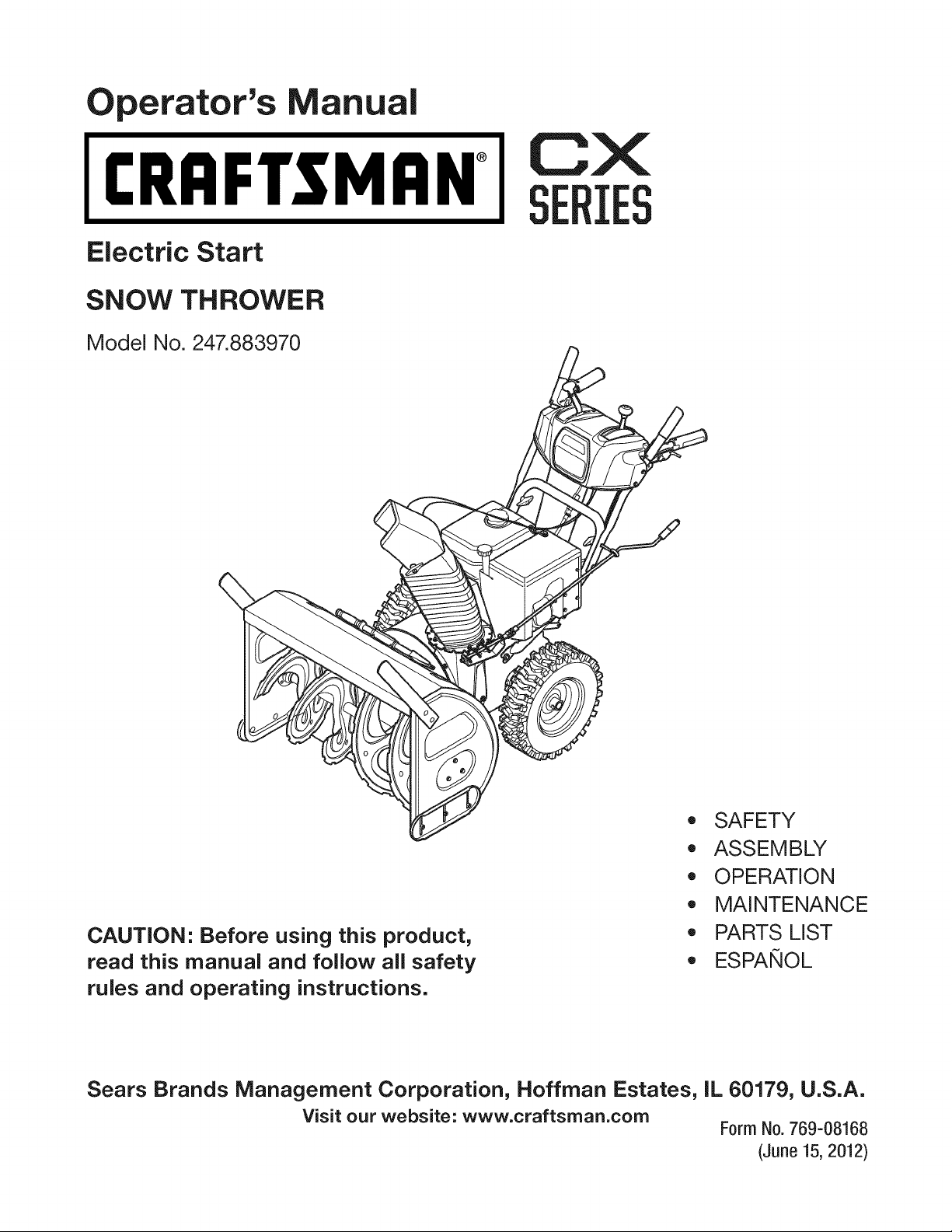
perator's nual
I:RRFrSMAN+
Electric Start
SNOW THROWER
Model No. 247.883970
CX
IES
CAUTION" Before using this product,
read this manual and follow all safety
rules and operating instructions.
,, SAFETY
o ASSEMBLY
OPERATION
MAINTENANCE
PARTS LIST
o ESPANOL
Sears Brands Management Corporation, Hoffman Estates, IL 60179, U.S.A.
Visit our website: www.craftsman.com Form No. 769-08168
(June 15, 2012)
Warranty Statement .................................. Page 2
Safe Operation Practices .......................... Page 3
Safety Labels ............................................ Page 7
Assembly .................................................. Page 8
Operation .................................................. Page 13
Service and Maintenance ......................... Page 18
Off-Season Storage .................................. Page 26
Troubleshooting ........................................ Page 27
Parts List ................................................... Page 28
Repair Protection Agreement ................... Page 47
Espafiol ..................................................... Page 48
Service Numbers ...................................... Back Cover
CRAFTSMANCXTWOYEAR FULL WARRANTY
FORTWOYEARSfromthe dateof purchase,thisproductis warrantedagainstanydefectsin materialor workmanship.A defective
productwill receivefree repairor replacementif repairis unavailable.
Forwarranty coverage details to obtain free repairor replacement,visitthe web site: www.craftsman.com
Thiswarranty coversONLYdefects in material andworkmanship. Warranty coveragedoes NOTinclude:
• Expendableitemsthatcan wearoutfromnormalusewithinthe warrantyperiod,includingbutnot limitedto augers,augerpaddles,
driftcutters,skidshoes,shaveplate,shearpins,sparkplug,aircleaner,belts,andoil filter.
•Standardmaintenanceservicing,oilchanges,or tune-ups.
•Tire replacementor repaircausedby puncturesfromoutsideobjects,suchas nails,thorns,stumps,or glass.
•Tireor wheelreplacementor repairresultingfromnormalwear,accident,or improperoperationor maintenance.
•Repairsnecessarybecauseof operatorabuse,includingbut notlimitedto damagecausedbyover-speedingthe engine,or from
impactingobjectsthat bendthe frame,augershaft,etc.
•Repairsnecessarybecauseof operatornegligence,includingbutnot limitedto,electricaland mechanicaldamagecausedby
improperstorage,failureto usethe propergradeandamountof engineoil,or failureto maintainthe equipmentaccordingto the
instructionscontainedinthe operator'smanual.
•Engine(fuel system)cleaningor repairscausedbyfuel determinedto becontaminatedor oxidized(stale). Ingeneral,fuel shouldbe
usedwithin30 daysof its purchasedate.
•Normaldeteriorationandwearof the exteriorfinishes,orproductlabelreplacement.
Thiswarrantyis void if this productisever usedwhileprovidingcommercialservicesor if rentedto anotherperson.
Thiswarrantygivesyou specificlegalrights,andyoumayalsohaveother rightswhichvaryfromstateto state.
Sears Brands ManagementCorporation, Hoffman Estates, IL 60179
EngineOilType: 5W-30
EngineOilCapacity: 37ounces
FuelCapacity: Approx.5 Quarts
SparkPlug: F6RTC(951-10292)
SparkPlugGap: .020"to .030"
Model Number.................................................................
Serial Number .................................................................
Dateof Purchase.............................................................
Recordthe modelnumber,serialnumber
anddateof purchaseabove
© Sears Brands,LLC
2
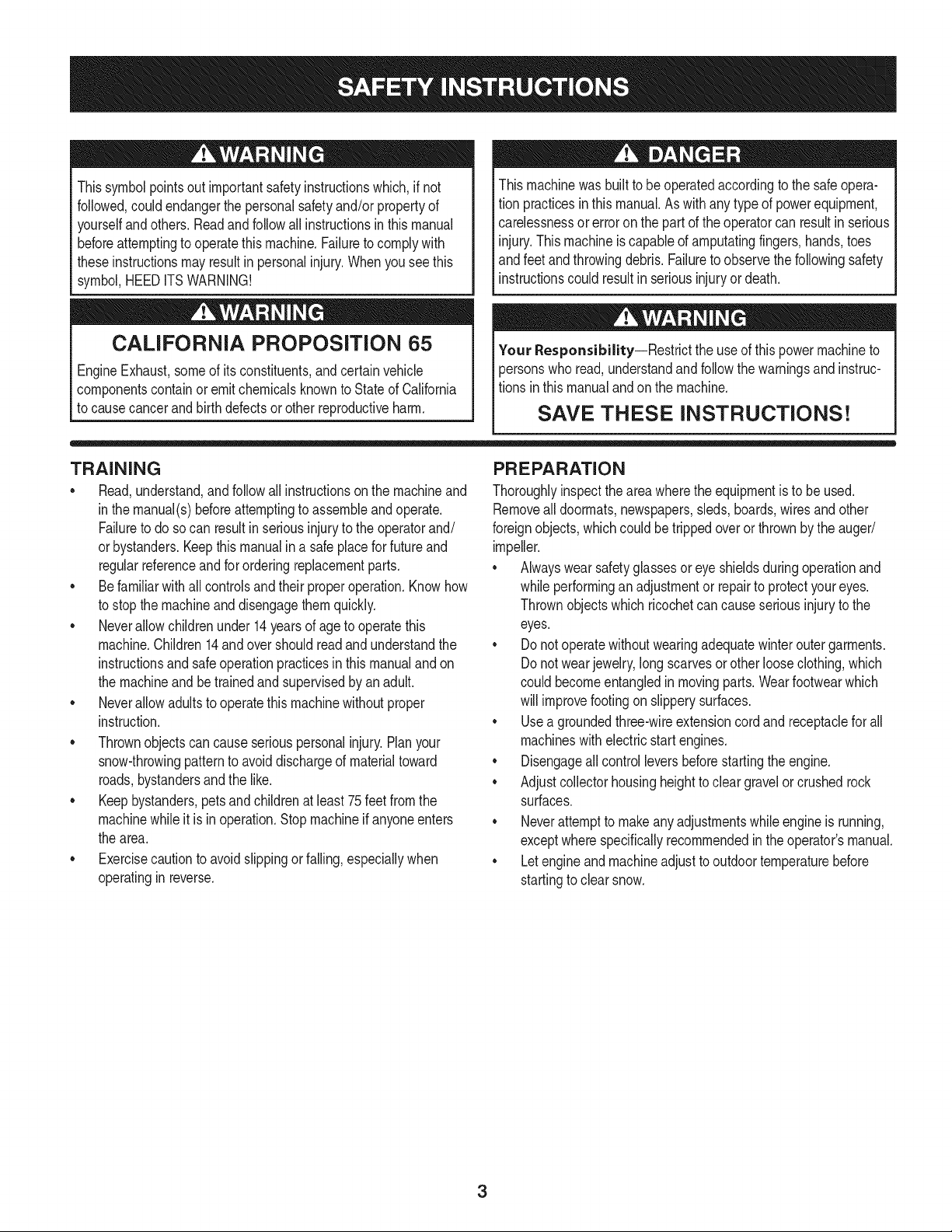
Thissymbolpointsout importantsafetyinstructionswhich,if not
followed,couldendangerthepersonalsafetyand/orpropertyof
yourselfandothers. Readandfollowall instructionsin thismanual
beforeattemptingto operatethismachine.Failureto complywith
theseinstructionsmayresultin personalinjury.Whenyou seethis
symbol,HEEDITSWARNING!
CALIFORNIA PROPOSITION 65
EngineExhaust,someof itsconstituents,andcertainvehicle
componentscontainoremitchemicalsknownto Stateof California
to causecancerandbirthdefectsorotherreproductiveharm,
Thismachinewasbuiltto beoperatedaccordingto the safeopera-
tion practicesinthis manual.As withanytypeof powerequipment,
carelessnessorerroron the partof the operatorcan resultin serious
injury.Thismachineis capableof amputatingfingers,hands,toes
andfeetandthrowingdebris.Failureto observethe followingsafety
instructionscouldresultin seriousinjuryor death.
Your Responsibility--Restrict the useof thispowermachineto
personswho read,understandandfollowthewarningsand instruc-
tionsin thismanualandon the machine.
SAVE THESE INSTRUCTIONS!
TRAiNiNG
•Read,understand,andfollowall instructionson the machineand
in themanual(s)beforeattemptingto assembleandoperate.
Failureto do socan resultinseriousinjuryto the operatorand/
orbystanders.Keepthismanualin a safeplaceforfutureand
regularreferenceandfor orderingreplacementparts.
• Befamiliarwithall controlsandtheir properoperation.Knowhow
to stopthe machineanddisengagethemquickly.
• Neverallowchildrenunder14yearsof ageto operatethis
machine.Children14andover shouldreadandunderstandthe
instructionsandsafeoperationpracticesin thismanualandon
the machineandbe trainedandsupervisedby anadult.
Neverallowadultsto operatethis machinewithoutproper
instruction.
• Thrownobjectscan causeseriouspersonalinjury.Planyour
snow-throwingpatternto avoiddischargeof materialtoward
roads,bystandersandthe like.
Keepbystanders,petsandchildrenat least75feetfromthe
machinewhile it is in operation.Stopmachineif anyoneenters
the area.
• Exercisecautionto avoidslippingor falling,especiallywhen
operatingin reverse.
PREPARATION
Thoroughlyinspecttheareawherethe equipmentisto beused.
Removeall doormats,newspapers,sleds,boards,wiresandother
foreignobjects,whichcouldbe trippedoverorthrownby the auger/
impeller.
• Alwayswear safetyglassesor eyeshieldsduringoperationand
while performingan adjustmentor repairto protectyoureyes.
Thrownobjectswhichricochetcancauseseriousinjuryto the
eyes.
Donot operatewithoutwearingadequatewinteroutergarments.
Donot wearjewelry,longscarvesorotherlooseclothing,which
could becomeentangledin movingparts.Wearfootwearwhich
will improvefootingonslipperysurfaces.
Usea groundedthree-wireextensioncordand receptaclefor all
machineswithelectricstartengines.
Disengageall controlleversbeforestartingthe engine.
Adjustcollectorhousingheightto cleargravelorcrushedrock
surfaces.
• Neverattemptto makeanyadjustmentswhileengineis running,
exceptwherespecificallyrecommendedinthe operator'smanual.
Letengineandmachineadjustto outdoortemperaturebefore
startingto clearsnow.
3

Safe Handling of Gasoline
Toavoidpersonalinjuryor propertydamageuseextremecare in
handlinggasoline.Gasolineis extremelyflammableandthe vaporsare
explosive.Seriouspersonalinjurycan occurwhengasolineis spilled
onyourselfor yourclotheswhichcan ignite. Washyour skinand
changeclothesimmediately.
• Useonlyan approvedgasolinecontainer.
• Extinguishallcigarettes,cigars,pipesandother sourcesof
ignition.
• Neverfuel machineindoors.
• Neverremovegas capor addfuel whilethe engineis hot or
running.
• Allowengineto coolat leasttwo minutesbeforerefueling.
• Neveroverfill fueltank. Fill tankto nomorethan1/2inchbelow
bottomof filler neckto providespaceforfuel expansion.
• Replacegasolinecapandtightensecurely.
• Ifgasolineis spilled,wipe it off theengineandequipment.Move
machineto anotherarea.Wait5 minutesbeforestartingthe
engine.
• Neverstorethe machineorfuel containerinsidewherethereis an
openflame,sparkor pilotlight(e.g.furnace,waterheater,space
heater,clothesdryeretc.).
• Allowmachineto cool at least5 minutesbeforestoring.
• Neverfill containersinsidea vehicleor ona truckor trailerbed
witha plasticliner.Alwaysplacecontainersonthe groundaway
fromyour vehiclebeforefilling.
• If possible,removegas-poweredequipmentfromthe truckor
trailerandrefuelit onthe ground.Ifthis is not possible,then refuel
suchequipmenton a trailerwitha portablecontainer,ratherthan
froma gasolinedispensernozzle.
• Keepthe nozzlein contactwiththe rimof the fuel tankor
containeropeningat alltimes untilfuelingis complete.Do not use
a nozzlelock-opendevice.
OPERATION
•Do not puthandsorfeetnear rotatingparts,in the auger/impeller
housingor chuteassembly.Contactwiththe rotatingpartscan
amputatehandsandfeet.
• Theauger/impellercontrolleveris a safetydevice.Neverbypass
itsoperation.Doingso makesthe machineunsafeandmaycause
personalinjury.
• Thecontrolleversmustoperateeasilyin bothdirectionsand
automaticallyreturnto the disengagedpositionwhenreleased.
• Neveroperatewitha missingor damagedchuteassembly.Keep
all safetydevicesin placeandworking.
• Neverrunanengineindoorsor ina poorlyventilatedarea. Engine
exhaustcontainscarbonmonoxide,anodorlessanddeadlygas.
• Do notoperatemachinewhileunderthe influenceof alcoholor
drugs.
• Mufflerandenginebecomehotandcan causea burn.Do not
touch.Keepchildrenaway.
• Exerciseextremecautionwhenoperatingon orcrossinggravel
surfaces.Stayalertfor hiddenhazardsor traffic.
Exercisecautionwhenchangingdirectionandwhileoperatingon
slopes.Do notoperateon steepslopes.
Planyoursnow-throwingpatternto avoiddischargetowards
windows,walls,carsetc. Thus,avoidingpossibleproperty
damageor personalinjurycausedby a ricochet.
Neverdirectdischargeat children,bystandersand petsor allow
anyoneinfrontof the machine.
Donot overloadmachinecapacityby attemptingto clearsnowat
too fastof a rate.
Neveroperatethis machinewithoutgoodvisibilityorlight.Always
be sureof yourfootingand keepa firmholdon the handles.Walk,
neverrun.
Disengagepowerto theauger/impellerwhentransportingor not
in use.
Neveroperatemachineat hightransportspeedson slippery
surfaces.Lookdownand behindand usecare whenbackingup.
Ifthe machineshouldstart to vibrateabnormally,stopthe engine,
disconnectthe sparkplugwire andgroundit againstthe engine.
Inspectthoroughlyfor damage.Repairanydamagebefore
startingandoperating.
Disengageall controlleversandstopenginebeforeyouleave
the operatingposition(behindthe handles).Waituntilthe auger/
impellercomesto a completestopbeforeuncloggingthechute
assembly,makingany adjustments,or inspections.
Neverput yourhandinthe dischargeor collectoropenings.Do
not unclogchuteassemblywhileengineis running.Shutoff
engineand remainbehindhandlesuntilall movingpartshave
stoppedbeforeunclogging.
Useonly attachmentsandaccessoriesapprovedby the manufac-
turer (e.g.wheelweights,tire chains,cabsetc.). Forinformation
concerningtheseitems,call 1-800-469-4663.
Whenstartingengine,pullcord slowlyuntilresistanceis felt, then
pull rapidly.Rapidretractionof startercord(kickback)will pull
handandarmtowardenginefasterthan youcan let go. Broken
bones,fractures,bruisesor sprainscould result.
Ifsituationsoccurwhichare notcoveredinthis manual,use care
andgoodjudgment.
Toorderpartsor scheduleservicefor thisproduct,call 1-800-
469-4663.
CLEARING ACLOGGED DISCHARGE CHUTE
Handcontactwiththe rotatingimpellerinsidethe dischargechute
is the mostcommoncauseof injuryassociatedwithsnowthrowers.
Neveruse yourhandto cleanout thedischargechute.
Toclear thechute:
1. SHUTTHEENGINEOFF!
2. Wait 10secondsto be surethe impellerbladeshavestopped
rotating.
3. Alwaysusea clean-outtool, not yourhands.
4
MAINTENANCE & STORAGE
•Nevertamperwithsafetydevices.Checktheirproperoperation
regularly.Referto the maintenanceandadjustmentsectionsof
thismanual.
• Beforecleaning,repairing,or inspectingmachinedisengageall
controlleversandstopthe engine.Waituntilthe auger/impeller
cometo a completestop.Disconnectthe sparkplugwireand
groundagainsttheengineto preventunintendedstarting.
Checkboltsand screwsfor propertightnessat frequentintervals
to keepthe machineinsafeworkingcondition.Also,visually
inspectmachinefor anydamage.
Do notchangetheenginegovernorsettingor over-speedthe
engine.Thegovernorcontrolsthe maximumsafeoperatingspeed
of the engine.
Snowthrowershaveplatesand skidshoesaresubjectto wear
anddamage.Foryoursafetyprotection,frequentlycheckall
componentsand replacewithoriginalequipmentmanufacturer's
(OEM)partsonlyas listedinthe Partspagesof thisoperator's
manual.Useof partswhichdonot meetthe originalequipment
specificationsmayleadto improperperformanceandcompro-
misesafety!
Checkcontrolleversperiodicallyto verifytheyengageanddisen-
gageproperlyandadjust,if necessary.Referto the adjustment
sectioninthisoperator'smanualfor instructions.
Maintainor replacesafetyandinstructionlabels,as necessary.
Observeproperdisposallawsand regulationsfor gas,oil,etc. to
protectthe environment.
Priorto storing,runmachinea few minutestoclear snowfrom
machineand preventfreezeupof auger/impeller.
Neverstorethe machineorfuel containerinsidewherethereisan
openflame,sparkorpilot lightsuchas a waterheater,furnace,
clothesdryer etc.
Alwaysreferto the operator'smanualfor properinstructionson
off-seasonstorage.
Checkfuelline,tank, cap,andfittingsfrequentlyfor cracksor
leaks.Replaceif necessary.
Do notcrankenginewithsparkplugremoved.
Accordingto the ConsumerProductsSafetyCommission(CPSC)
andthe U.S.EnvironmentalProtectionAgency(EPA),thisproduct
hasan AverageUsefulLifeof seven(7)years,or 60 hoursof
operation.At the endof theAverageUsefulLifehavethe machine
inspectedannuallybyan authorizedservicedealerto ensurethat
allmechanicalandsafetysystemsareworkingproperlyand not
wornexcessively.Failureto do so can resultinaccidents,injuries
ordeath.
DO NOT MODIFY ENGINE
Toavoidseriousinjuryor death,do not modifyengineinany way.
Tamperingwiththe governorsettingcanleadto a runawayengineand
causeit to operateat unsafespeeds.Nevertamperwithfactorysetting
of enginegovernor.
NOTICE REGARDING EMiSSiONS
EngineswhicharecertifiedtocomplywithCaliforniaandfederal
EPAemissionregulationsfor SORE(SmallOff RoadEquipment)are
certifiedto operateon regularunleadedgasoline,and mayinclude
the followingemissioncontrolsystems:EngineModification(EM),
OxidizingCatalyst(OC),SecondaryAirInjection(SAI)and ThreeWay
Catalyst(TWO)if so equipped.
SPARK ARRESTOR
Thismachineisequippedwithaninternalcombustionengineand
shouldnotbe usedonor nearany unimprovedforest-covered,
brush-coveredorgrass-coveredlandunlessthe engine'sexhaust
systemisequippedwitha sparkarrestormeetingapplicablelocalor
statelaws(if any)
Ifa sparkarrestoris used,it shouldbe maintainedin effectiveworking
orderby theoperator.Inthe Stateof Californiathe aboveis required
bylaw (Section4442of the CaliforniaPublicResourcesCode).Other
statesmayhavesimilarlaws. Federallawsapplyonfederallands.
A sparkarrestorfor the muffleris availablethroughyournearestSears
PartsandRepairServiceCenter.
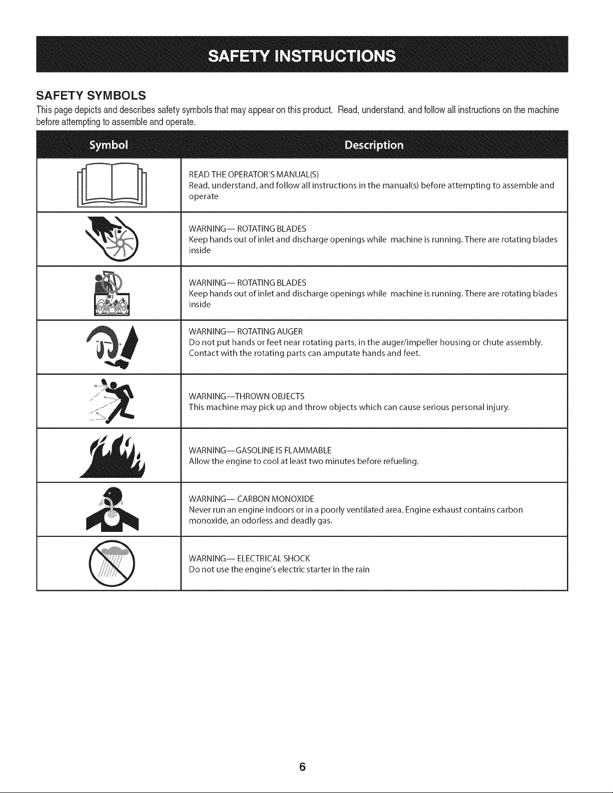
SAFETY SYMBOLS
Thispagedepictsanddescribessafetysymbolsthatmayappearonthisproduct. Read,understand,andfollowall instructionson the machine
beforeattemptingto assembleandoperate.
. +
i
i
"JIp
READ THE OPERATOR'S MANUAL(S)
Read, understand, and follow all instructions in the manual(s) before attempting to assemble and
operate
WARNING-- ROTATING BLADES
Keep hands out of inlet and discharge openings while machine is running. There are rotating blades
inside
WARNING-- ROTATING BLADES
Keep hands out of inlet and discharge openings while machine is running. There are rotating blades
inside
WARNING-- ROTATING AUGER
Do not put hands or feet near rotating parts, in the auger/impeller housing or chute assembly.
Contact with the rotating parts can amputate hands and feet.
WARNING--THROWN OBJECTS
This machine may pick up and throw objects which can cause serious personal injury.
WARNING--GASOLINE IS FLAMMABLE
Allow the engine to cool at least two minutes before refueling.
WARNING-- CARBON MONOXIDE
Never run an engine indoors or in a poorly ventilated area. Engine exhaust contains carbon
monoxide, an odorless and deadly gas+
WARNING-- ELECTRICAL SHOCK
Do not use the engine's electric starter in the rain
6
r
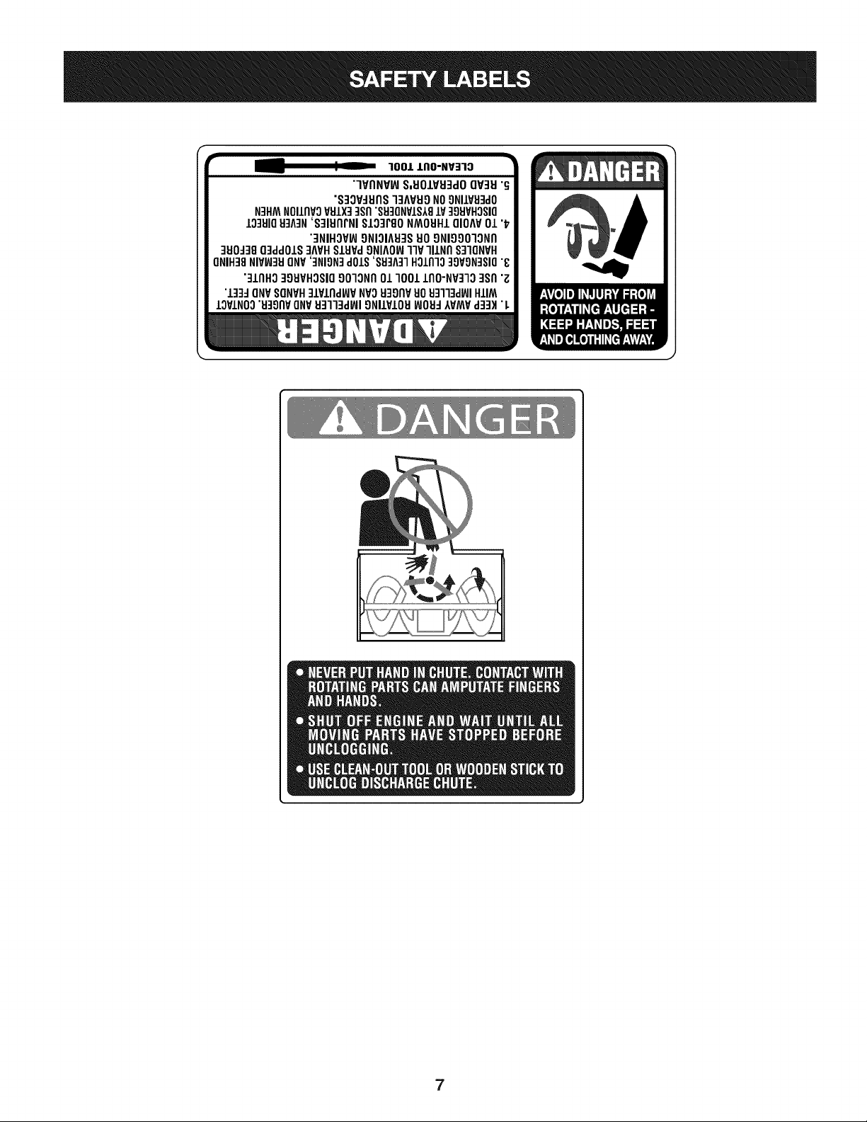
100/.LIIO-NV:IIO
"lVflNV_ S,UOIVU3dOQV3H"G
"S3OV_IJflS]3AVUONO9NIIV_J3dO
N3HMNOIIflVOVSIX] qsfl"S9]ONVIS181V]98VHOSIO
10381083A3N'S]IUflrNI SI03PgoNMOUHIQIOAV01 "_
"3NIHOV_ONIOIA83SUOONIOOO]ONfl
]UO_38O3ddOIS]AVHSlHPd9NIAOW11VlllNfl S]IQNVH
ONIH]8NIVW3UONV']NION]dOlS'88]A]1HOlnlo]9VON]SIO"8
"]lnHg ]gHVHOSIO9010Nfl01 1001 lflO-NP]lO ]Sfl "Z
"l]]d ONVSONVH]lPlnd_P NVOH3onvuo Hq]l]d_JIHIIM
IOVINO0"u39npONV_J3113dWI9NllVIOU_JOH_IVMV d]3H "L
7
NOTE:Referencesto rightorleftsideofthe snowthroweraredetermined
fromtheoperatingpositionlookingforwardto thefrontof themachine.
Handle
REMOVING FROM CRATE
1. Removescrewsfrom the bottomof the crate securingthe sides,
andendsof the shippingcrate.
2. Lift off the top off of thecrate and set out of the way of the
assemblyarea.
3. Removeanddiscardplasticbag that coversunit.
4. Removeany looseparts includedwith unit(e.g.,Operator's
Manual,etc.).
5. Pushdownon the lowerhandleand pullunitbackout of crate.
6. Makecertainthe cratehas beencompletelyemptiedbefore
discardingit.
ASSEMBLY
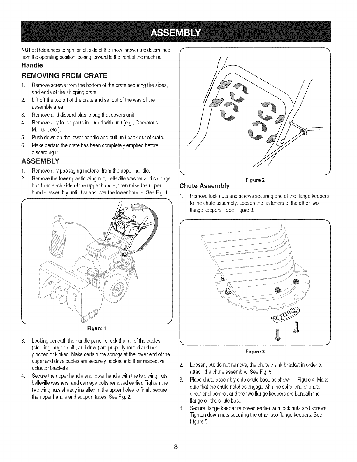
1. Removeany packagingmaterialfromthe upperhandle.
2. Removethe lowerplasticwing nut, bellevillewasherand carriage
bolt fromeachsideof the upperhandle;then raisethe upper
handleassemblyuntilit snapsoverthe lowerhandle.SeeFig. 1.
Figure 1
3. Lookingbeneaththe handlepanel,checkthatallof thecables
(steering,auger,shift,anddrive)areproperlyroutedand not
pinchedorkinked.Makecertainthe springsat thelowerend of the
augeranddrivecablesare securelyhookedintotheirrespective
actuatorbrackets.
4. Securethe upperhandleand lowerhandlewiththe twowingnuts,
bellevillewashers,andcarriageboltsremovedearlier.Tightenthe
twowingnutsalreadyinstalledintheupperholesto firmlysecure
the upperhandleandsupporttubes.See Fig.2.
Chute Assembly
Figure 2
,,J
1. Removelock nuts and screwssecuringoneof the flangekeepers
to the chuteassembly.Loosenthe fastenersof the othertwo
flangekeepers. See Figure3.
\
Figure 3
2. Loosen,but do not remove,the chutecrankbracketinorderto
attachthe chuteassembly. SeeFig. 5.
3. Placechuteassemblyontochutebaseas shownin Figure4. Make
surethatthechutenotchesengagewiththespiralend of chute
directionalcontrol,andthe twoflangekeepersarebeneaththe
flangeonthe chutebase.
4. Secureflangekeeperremovedearlierwith lock nutsand screws.
Tightendownnutssecuringthe othertwo flangekeepers.See
Figure5.
8
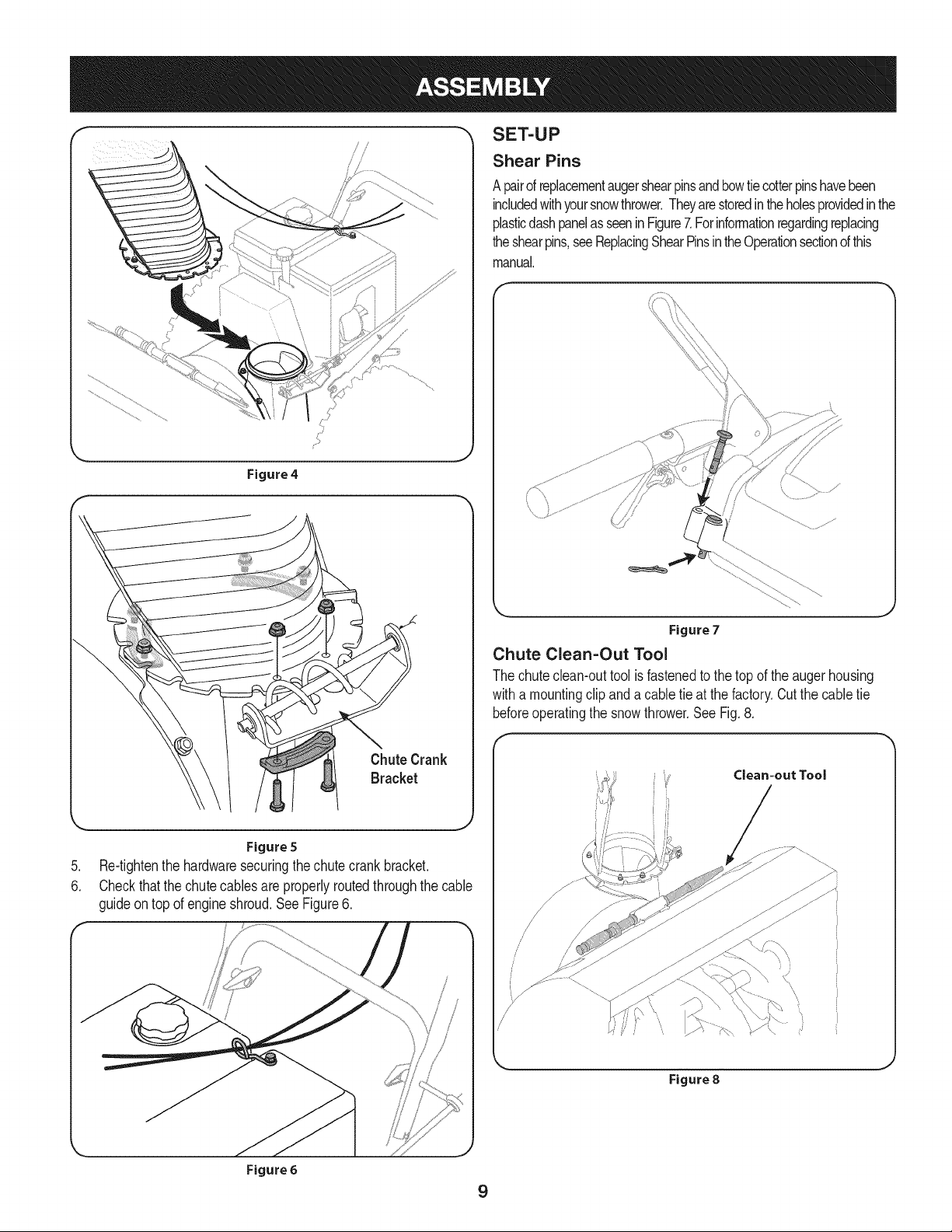
Figure4
SET-UP
Shear Pins
A pairof replacementaugershearpinsandbowtiecotterpinshavebeen
includedwithyoursnowthrower.Theyarestoredintheholesprovidedinthe
plasticdashpanelas seeninFigure7.Forinformationregardingreplacing
theshearpins,seeReplacingShearPinsintheOperationsectionofthis
manual.
\ \
Figure7
Chute Clean-Out Tool
The chuteclean-outtool isfastenedto thetop of the augerhousing
witha mountingclip anda cabletie at the factory.Cutthe cabletie
beforeoperatingthe snowthrower.See Fig.8.
,J
.
6.
Figure 5
Re-tightenthe hardwaresecuringthechutecrank bracket.
Checkthatthe chutecables are properlyroutedthroughthe cable
guideon top of engineshroud.See Figure6.
/
/
/
/
/
/
\
Figure 8
Figure 6
9
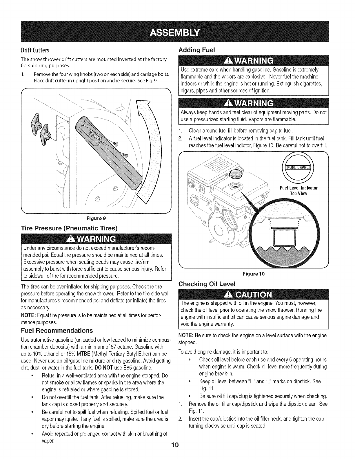
Drift (:utters
The snow thrower drift cutters are mounted inverted at the factory
for shipping purposes.
1. Remove the four wing knobs (two on each side) and carriage bolts.
Place drift cutter in upright position and re-secure. See Fig. 9.
Figure 9
Tire Pressure (Pneumatic Tires)
Underanycircumstancedo notexceedmanufacturer'srecom-
mendedpsi. Equaltire pressureshouldbe maintainedat all times.
Excessivepressurewhenseatingbeadsmaycausetire/rim
assemblyto burstwith force sufficientto causeseriousinjury.Refer
to sidewallof tirefor recommendedpressure.
Thetirescan beover-inflatedfor shippingpurposes.Checkthetire
pressurebeforeoperatingthe snowthrower. Referto thetire side wall
for manufactures'srecommendedpsi and deflate(or inflate)the tires
as necessary.
NOTE:Equaltire pressureisto bemaintainedat alltimesforperfor-
mancepurposes.
Fuel Recommendations
Useautomotivegasoline(unleadedor low leadedto minimizecombus-
tionchamberdeposits)witha minimumof 87octane.Gasolinewith
upto 10%ethanolor 15%MTBE(MethylTertiaryButyl Ether)canbe
used.Neverusean oil/gasolinemixtureor dirty gasoline.Avoidgetting
dirt,dust,or waterinthefuel tank. DONOTuse E85gasoline.
•Refuelin awell-ventilatedareawiththe enginestopped.Do
not smokeorallow flamesor sparksin the areawherethe
engineis refueledor wheregasolineisstored.
•Do notoverfillthe fuel tank.Afterrefueling,makesurethe
tankcap isclosedproperlyandsecurely.
•Becarefulnot to spillfuel when refueling.Spilledfuelor fuel
vapormayignite.Ifany fuel is spilled,makesurethe areais
dry beforestartingthe engine.
•Avoidrepeatedorprolongedcontactwith skinor breathingof
vapor.
Adding Fuel
Useextremecare whenhandlinggasoline.Gasolineis extremely
flammableandthe vaporsare explosive. Neverfuel themachine
indoorsorwhile theengineishotor running.Extinguishcigarettes,
cigars,pipesandother sourcesof ignition.
Alwayskeephandsandfeet clear of equipmentmovingparts.Do not
usea pressurizedstartingfluid.Vaporsare flammable.
.
2.
Cleanaroundfuel fill beforeremovingcap to fuel.
A fuel levelindicatoris locatedin the fueltank. Fill tank untilfuel
reachesthe fuel levelindictor,Figure10. Becarefulnotto overfill.
Fuel Level Indicator
TopView
J
Figure 10
Checking Oil Level
The engineis shippedwithoil in theengine.Youmust,however,
checkthe oil levelpriorto operatingthe snowthrower.Runningthe
enginewith insufficientoil cancauseseriousengine damageand
void theenginewarranty.
NOTE: Besureto checkthe engineon a levelsurfacewiththe engine
stopped.
Toavoidenginedamage,it is importantto:
• Checkoil levelbeforeeachuse andevery5 operatinghours
whenengineis warm.Checkoil levelmorefrequentlyduring
enginebreak-in.
• Keepoil level between"H" and "L"markson dipstick.See
Fig.11.
• Besureoilfill cap/plugis tightenedsecurelywhenchecking.
1. Removethe oil filler cap/dipstickand wipe thedipstickclean. See
Fig.11.
2. Insertthe cap/dipstickintothe oil fillerneck,and tightenthe cap
turningclockwiseuntilcap is seated.
10

F
Figure 11
NOTE:On someengines,athreadedscrewcap will bepresent
insteadof thequarterturn lockingcap.In the instanceof a threadedoil
cap/dipstick,DO NOTscrewthecap/dipstickin to check.Checkthe oil
by restingthecap/dipstickon thethreads,butnot screwingit in.
3. Removetheoil fillercap/dipstick,ifthe levelislow,slowlyadd oil
untiloil levelregistersbetweenhigh(H) andlow(L), Fig.11.
4. Replaceandtightencap/dipstickfirmlybeforestartingengine.
NOTE: Donot overfill.Overfillingwithoil maycausesmoking,hard
starting,or sparkplugfouling.
NOTE: DONOTallowoil levelto fall belowthe"L"mark on the
dipstick.Doingso mayresultin equipmentmalfunctionsordamage.
NOTE:Tochangethe oilon yourengine,see the MaintenanceSec-
tionof theengineoperator'smanualincludedwith the snowthrower.
ADJUSTMENTS
Skid Shoes
Thesnowthrowerskidshoesare adjustedupwardat thefactory for
shippingpurposes.Adjustthemdownwardpriorto operatingthe snow
thrower.
It is not recommendedthat youoperatethis snowthrowerongravel
as it can easilypick upandthrowloosegravel,causingpersonal
injuryor damageto the snowthrowerandsurroundingproperty.
Forclosesnowremovalona smoothsurface,adjusttheskidshoessothat
theshaveplateonthe bottomofthe augerhousingisjustoff theground.
Adjustthe skidshoesto a lowerpositionto raisethe shaveplateoff the
groundwhenclearingunevenareas,suchas a ribbontypedrivewayor
a graveldriveway
NOTE: Ifyou chooseto operatethe snowthrowerona gravelsurface,
keepthe skidshoesin positionfor maximumclearancebetweenthe
groundandthe shaveplate.
To adjust the skid shoes:
1. Adjustskidshoesby looseningthesix (threeoneachside) hex
nutsandcarriagebolts securingthe skid shoesto the auger
housing. Referto Figure12.
2. Whileobservingthedistancebetweenthe shaveplateand the
ground,adjustthe skidsshoesup or downto achievethe desired
shaveplateheight.See Figure12.
3. Makecertainthe entirebottomsurfaceof skid shoesare against
the groundto avoidunevenwearon theskidshoes;then tighten
nutsandbolts securely.
ShavePlate
Lower
Shave
Plate
Raise
Shave
Plate
Figure 12
AUGER AND DRIVE CONTROL CABLES
Priorto operatingyoursnowthrower,carefullyreadandfollowall
instructionsbelow.Performalladjustmentsto verifyyoursnowthrower
isoperatingsafelyandproperly.
Testing Auger Drive Control
1. Whenthe augercontrolis releasedandinthe disengaged"up"
position,the cable shouldhaveverylittle slack. It shouldNOTbe
tight. Referto Figure13.
2. Ina well-ventilatedarea,startthe snow throwerengineas
instructedinthe Operationsectionof this manual.Makesurethe
throttleis setinthe FASTposition.
3. Whilestandingin theoperator'sposition(behindthe snow
thrower),engagethe auger.
4. Allowtheaugerto remainengagedforapproximatelyten(10)sec-
ondsbeforereleasingthe augercontrol.Repeatthisseveraltimes.
NOTE:Whenengagingtheauger,youmayheara"chirp"sound.
Thisisnormal,itisthe beltengagingthe pulley.As thebeltwears,this
soundwillnotbeheardwhenengagingtheauger.
5. With the throttlecontrolinthe FAST(rabbit)positionand the
augercontrolinthe disengaged"up" position,walkto the frontof
the machine.
11

6. Confirmthat the augerhas completelystoppedrotatingand
showsNOsignsof motion.Ifthe augershowsANY signsof
rotating,immediatelyreturnto the operator'spositionand shutoff
theengine.Waitfor ALL movingparts to stop beforere-adjusting
theaugercontrol.
Testing Drive Control &Speed Selector Lever
1. Withthe engine turnedoff, movethe speedselectorleverinto
sixth(6) position.Referto Figure13.
2. Withthe wheeldrivecontrol released,pushthe snowthrower
forward,thenpull it back.The machineshouldmovefreely.
3. Engagethe drivecontroland attemptto movethe machineboth
forwardandback,resistanceshouldbe felt.
4. Movethe speedselector leverinto thefast reverse(R2)position
andrepeattheprevioustwo steps.
5. If you experiencedresistancerollingthe unit, eitherwhen
repositioningthe speedselector leverfrom6 to R2 orwhen
attemptingto movethe machinewiththe drivecontrol released,
adjustthe drivecontrolimmediately.See AdjustingDriveand
AugerControls.
ChuteTilt _eedSelector Lever
Auc
Control Control
Auger
Control
Cable
Drive
Cable
Figure 13
Adjusting Drive and Auger Controls
1. Frombeneaththe handle,pull downwardon the appropriatecable
andunhookthe springfoundon the end of the cablefrom its
respectiveactuatorbracket.Referto Figures14and 15.
2. Slidethe springup thecable to exposethe cablecouplerthreads
andlock nut. Referto Figure15.
3.
Rearwardmost holeof
the actuator brackets
Figure14
Adjustthe locknutas follows:If adjustingthe drivecable,thread
the locknut outward(downthe coupler)to lengthenthecable and
allowthe unit to movefreelywhenthe controlis released.Thread
the locknut inward(up thecoupler)to shortenthe cableto reduce
slippageand preventthe machinefrombeingeasilymovedwith
the drivecontrolengaged.
Donotover-tightenthecable.Over-tighteningmaypreventtheauger
shaftfromdisengagingandcompromisethesafetyof thesnowthrower.
4. If adjustingthe auger cable,threadthelock nutoutwardstowards
endof threadto lengthenthe cableas necessaryto stopthe
augershaftfrom turningwhenthe controlis released.
5. Securelyhookeachcable'sspringintothe appropriateholeof the
respectiveactuatorbracket.Bothcableshookintothe rearward-
most holein eachbracket,as shownin Figure14.
6. Repeatthe wheeldriveand augercontroltests to verifyproper
adjustment.Repeatpreviousstepsif necessaryto attainproper
adjustmentof eachcable.
12
Figure 15
fWhen DriveControl
Headlight _eedSeJectorLever
ChutePitchControl"
FueJTank
ger Control
FuelCap
Oil Fill WheelSteering Control
DriftCutter
ChuteAssembly ChuteDirectionalControl
AugerHousing
_Skid Shoe
Primer
OilFiller
Cap/Dipstick FuelFill
Key ; _ =Cap
OilDrain
Figure 16
Electric
Start
Button
Electric
Box
Starter Handle
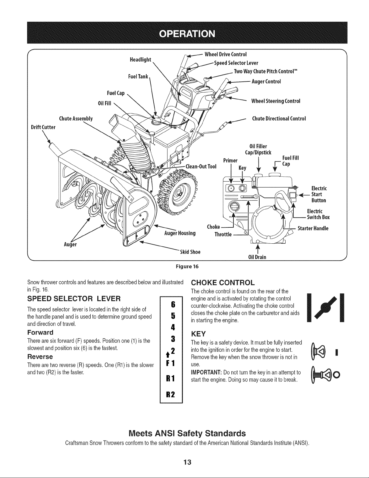
Snowthrowercontrolsandfeaturesare describedbelowand
in Fig.16.
SPEED SELECTOR LEVER
Thespeedselector leverislocatedinthe rightsideof
the handlepaneland is usedto determinegroundspeed
anddirectionof travel.
Forward
Therearesixforward(F) speeds.Positionone(1) is the
slowestand positionsix(6) is the fastest.
Reverse
Therearetworeverse(R) speeds.One(R1)is the slower
andtwo (R2) is the faster.
illustrated
6
5
4
3
t2
F1
R1
R2
CHOKE CONTROL
The chokecontrolis foundon the rearof the
engineand is activatedby rotatingthecontrol
counter-clockwise.Activatingthechokecontrol
closesthe chokeplateon thecarburetorandaids
instartingtheengine.
KEY
The keyis a safetydevice.Itmust befullyinserted
intothe ignitionin orderfor the engineto start.
Removethe keywhenthe snowthroweris not in
use.
IMPORTANT:Donotturn the keyinan attemptto
startthe engine.Doingso maycauseitto break.
Meets ANSi Safety Standards
CraftsmanSnowThrowersconformto the safetystandardof the AmericanNationalStandardsInstitute(ANSI).
13
THROTTLE CONTROL
Thethrottlecontrolis locatedon the rearof theengine.It regulatesthe
speedof the engineandwill shutoff the enginewhenmovedintothe
STOPposition.
PRIMER
Pressingthe primerforcesfuel directlyintothe
engine'scarburetorto aid in startinga "Cold" qkfP------=---
engine,or restartinga warmengine. I
OIL FILL
Engineoillevelcan be checkedand oil added
throughthe oilfill.
OIL DRAIN
Engineoilcan be drainedthroughtheoil drain.
FUEL CAP
Un-threadthe gascap to addgasolineto the fueltank.
MUFFLER
Engineexhaustexiststhe enginevia the muffler.
ELECTRIC STARTER OUTLET
Requiresthe useof a three-prongoutdoorextensioncordanda 120V
powersource/walloutlet.
RECOIL STARTER HANDLE
Thishandleis usedto manuallystartthe engine.
ELECTRIC STARTER BUTTON
Pressingthe electricstarterbuttonengagesthe engine'selectric
starterwhenpluggedintoa 120Vpowersource.
AUGER
Whenengaged,the augerbladesrotateand draw snowinto theauger
housing.
CHUTE ASSEMBLY
Snowdrawnintothe augerhousingis dischargedout the chute
assembly.
DRIFT CUTTERS
Thedrift cuttersaredesignedfor use indeepsnow.Theiruse is
optionalfor normalsnowconditions.Maneuverthe snowthrowerso
thatthe cutterspenetratea highstandingsnow drift to assist snow
fallingintothe augersfor throwing.
SKiD SHOES
Positionthe skidshoes basedon surfaceconditions.Adjustupward
for hard-packedsnow.Adjustdownwardwhenoperatingongravelor
crushedrocksurfaces.
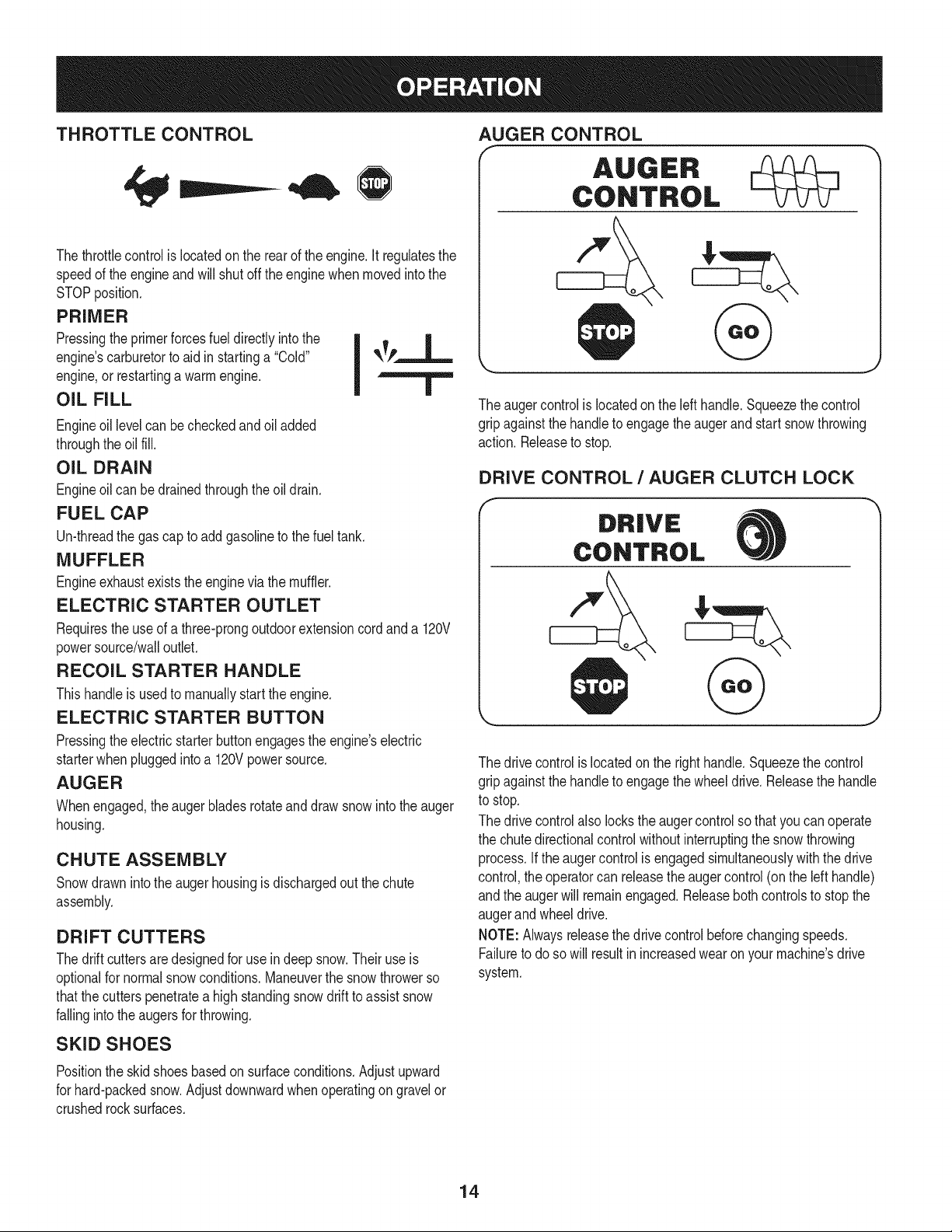
AUGER CONTROL
AUGER
CONTROL
&
The augercontrolis locatedon the lefthandle.Squeezethe control
gripagainstthe handleto engagethe augerand startsnowthrowing
action. Releaseto stop.
DRIVE CONTROL /AUGER CLUTCH LOCK
J
The drivecontrolis locatedon the righthandle.Squeezethe control
gripagainstthe handleto engagethe wheeldrive.Releasethe handle
to stop.
The drivecontrolalso lockstheaugercontrolso thatyoucan operate
the chutedirectionalcontrolwithoutinterruptingthe snowthrowing
process.If theaugercontrolis engagedsimultaneouslywith thedrive
control,theoperatorcan releasethe augercontrol(on the left handle)
andthe augerwill remainengaged.Releasebothcontrolsto stop the
augerand wheeldrive.
NOTE: Alwaysreleasethe drivecontrolbeforechangingspeeds.
Failureto doso will resultin increasedwearonyour machine'sdrive
system.
14
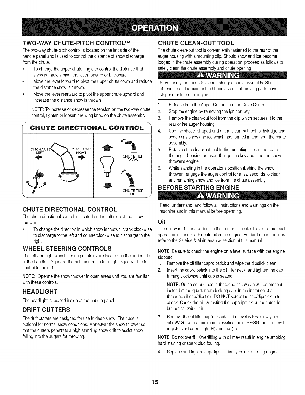
TWO-WAY CHUTE-PITCH CONTROLTM
Thetwo-waychute-pitchcontrolis locatedon the leftsideof the
handlepaneland isusedto controlthe distanceof snowdischarge
fromthechute.
• Tochangetheupper chuteangle to controlthe distancethat
snowisthrown,pivotthe leverforwardor backward.
Movethe leverforwardto pivotthe upperchutedownand reduce
the distancesnowisthrown.
Movethe leverrearwardto pivotthe upperchuteupwardand
increasethe distancesnowisthrown.
NOTE:To increaseordecreasethe tensionon the two-waychute
control,tightenor loosenthewing knobonthe chuteassembly.
CHUTE DiRECTiONAL CONTROL
DiscHARG oiscHARGE
a
V
.,j
i
i
CH UTE TILT
DOV_I
CHUTE TILT
UP .J
CHUTE DiRECTiONAL CONTROL
Thechutedirectionalcontrolislocatedon the leftsideof the snow
thrower.
Tochangethe directioninwhichsnow isthrown,crank clockwise
to dischargeto the leftand counterclockwiseto dischargeto the
right.
WHEEL STEERING CONTROLS
The[eft andrightwheelsteeringcontrolsarelocatedon theunderside
of the handles.Squeezethe rightcontrolto turn right;squeezethe left
controlto turn left.
NOTE: Operatethesnowthrowerinopen areasuntilyou are familiar
withthesecontrols.
HEADLIGHT
Theheadlightis locatedinsideof the handlepanel.
DRIFT CUTTERS
Thedrift cuttersaredesignedfor use indeepsnow.Their useis
optionalfor normalsnowconditions.Maneuverthe snowthrowerso
thatthe cutterspenetratea highstandingsnowdrift to assist snow
fallingintothe augersfor throwing.
CHUTE CLEAN-OUT TOOL
The chuteclean-outtool isconvenientlyfastenedto the rearof the
augerhousingwith a mountingclip. Shouldsnowand icebecome
lodgedinthe chuteassemblyduringoperation,proceedas followsto
safelycleanthe chuteassemblyandchuteopening:
Neveruse yourhandsto cleara cloggedchuteassembly.Shut
off engineandremainbehindhandlesuntilall movingparts have
stoppedbeforeunclogging.
1. Releaseboththe AugerControlandthe DriveControl.
2. Stop theengineby removingthe ignitionkey.
3. Removethe clean-outtool fromtheclip which securesit tothe
rearof the augerhousing.
4. Usethe shovel-shapedend of the clean-outtool to dislodgeand
scoopanysnow andice whichhas formedinand nearthe chute
assembly.
5. Refastenthe clean-outtoolto themountingclip on the rearof
the augerhousing,reinsertthe ignitionkeyand start the snow
thrower'sengine.
6. Whilestandinginthe operator'sposition(behindthe snow
thrower),engagethe augercontrolfor a fewsecondsto clear
any remainingsnowand ice from thechute assembly.
BEFORE STARTING ENGINE
Read,understand,andfollow all instructionsand warningson the
machineandin this manualbeforeoperating.
Oil
The unitwas shippedwith oilin the engine.Checkoillevelbeforeeach
operationto ensureadequateoil inthe engine.Forfurtherinstructions,
referto the Service& Maintenancesectionof this manual.
NOTE:Besureto checkthe engineona levelsurfacewiththeengine
stopped.
1. Removethe oil filler cap/dipstickand wipe thedipstickclean.
2. Insertthe cap/dipstickintothe oil filler neck,and tightenthe cap
turningclockwiseuntilcap is seated.
NOTE:Onsomeengines,a threadedscrewcapwill be present
insteadof the quarterturn lockingcap. Inthe instanceof a
threadedoil cap/dipstick,DO NOTscrewthe cap/dipstickin to
check.Checkthe oil by restingthecap/dipstickon thethreads,
butnot screwingit in.
Removethe oilfiller cap/dipstick.If the levelis low,slowlyadd
oil (5W-30,witha minimumclassificationof SF/SG)untiloil level
registersbetweenhigh(H) and low (L).
NOTE:Donot overfill.Overfillingwithoil mayresultin enginesmoking,
hardstartingor sparkplugfouling.
4. Replaceand tightencap/dipstickfirmly beforestartingengine.
15
Gasoline
Useextremecarewhenhandlinggasoline.Gasolineisextremely
flammableandthe vaporsare explosive.Neverfuel the machine
indoorsor whilethe engineis hot or running.Extinguishcigarettes,
cigars,pipes andother sourcesof ignition.
Useautomotivegasoline(unleadedor low leadedto minimizecombus-
tionchamberdeposits)witha minimumof 87octane.Gasolinewith
upto 10%ethanolor 15%MTBE(MethylTertiaryButyl Ether)canbe
used.Neverusean oil/gasolinemixtureor dirty gasoline.Avoidgetting
dirt,dust,or waterin thefuel tank. DO NOTuse E85gasoline.
• Refuelin awell-ventilatedareawith the engine stopped.Donot
smokeor allowflamesorsparksinthe areawheretheengineis
refueledor wheregasolineis stored.
• Do notoverfillthe fuel tank.After refueling,makesurethe tank
cap is closedproperlyandsecurely.
• Be carefulnot to spillfuel when refueling.Spilledfuelor fuelvapor
mayignite.Ifany fuel is spilled,makesurethe area is dry before
startingtheengine.
• Avoidrepeatedor prolongedcontactwith skinor breathingof vapor
1. Cleanaroundfuelfill beforeremovingcap to fuelto preventdebris
fromenteringfueltank..
2. A fuel levelindicatoris locatedin the fuel tank. Filltank untilfuel
reachesthe fuel levelindictor.SeeFigure10 inset.Be carefulnot
to overfill.
STARTING THE ENGINE
Alwayskeephandsandfeetclear of movingparts.Do notuse a
pressurizedstartingfluid.Vaporsare flammable.
Ifyou havea groundedthree-prongreceptacle,proceedas follows.
Ifyou donot havethe properhousewiring, DONOT usethe electric
starterunderanyconditions.
1. Plugthe extensioncord intothe outletlocatedon the engine's
surface.Plugthe otherend of extensioncord intoa three-prong
120-volt,grounded,AC outletin a well-ventilatedarea.
2. Movethrottlecontrolto FAST(rabbit)_ position.
3. Movechoketo the CHOKEposition I.,.,¢1(coldenginestart).
NOTE: Ifthe engineis alreadywarm,placechokecontrolin the
RUNpositioninsteadof CHOKEI,,_¢I position.
4. Pushprimerthreetimes(3x), makingsureto covervent hole in
primerbulbwhenpushing.Ifengine is warm,pushprimeronly
once.Alwayscovervent hole whenpushing.Cool weathermay
requireprimingto be repeated.
5. Pushstarterbuttonto startengine.Oncetheengine starts,im-
mediatelyreleasestarterbutton.Electricstarteris equippedwith
thermaloverloadprotection;systemwill temporarilyshut-downto
allow starterto cool if electricstarterbecomesoverloaded.
To prolongstarterlife,use short startingcycles (5 secondsmaximum
then waitone minute).
6. As the enginewarms,slowlyrotatethechoke controlto the RUN
position.Ifthe enginefalters, restartengineand runwith choke
at half-chokepositionfor a shortperiodof time,and thenslowly
rotatethe chokeintothe RUNposition.
7. After engineis running,disconnectpowercord fromelectric
starter.Whendisconnecting,alwaysunplugthe end at the wall
outletbeforeunpluggingthe oppositeend fromthe engine.
Recoil Starter
NOTE:Allowtheengineto warmupfor a fewminutesafterstarting.
Theenginewill not developfull poweruntil it reachesoperating
temperatures.
1. Makecertain boththe augercontroland drivecontrolare in the
disengaged(released)position.
2. Insertkey into slot.Makesureit snapsinto place.Do notattempt
to turnthe key.
NOTE:The enginecannotstart withoutthe keyis fully insertedintothe
ignitionswitch.
Electric Starter
Theoptionalelectricstarteris equippedwitha groundedthree-wire
powercord andplug,and is designedto operateon 120volt AC
householdcurrent.It mustbeusedwith a properlygroundedthree-
prongreceptacleat all timesto avoidthe possibilityof electricshock.
Followall instructionscarefullypriorto operatingthe electricstarter.
DO NOTuse electricstarterin the rain.
Determinethatyourhome'swiringis a three-wiregroundedsystem.
Aska licensedelectricianif youarenot certain.
Donot pullthe starterhandlewhiletheenginerunning.
1. Movethrottlecontrolto FAST(rabbit)_1 position.
2. Movechoketo the CHOKEI,,,¢1position_(coldenginestart).If
engineis warm,placechokein the RUNposition.
3. Pushprimerthreetimes, makingsureto covervent holewhen
pushing.If engineis warm,pushprimeronly once.Alwayscover
venthole whenpushing.Coolweathermayrequireprimingto be
repeated.
4. Pullgentlyon thestarterhandleuntilit beginsto resist,thenpull
quicklyandforcefullyto overcomethe compression.Engineshould
start.Donot releasethe handleandallowit to snapback.Return
ropeSLOWLYto originalposition.If required,repeatthis step.
5. As the enginewarms,slowlyrotatethechoke controlto the RUN
position.Ifthe enginefalters, restartengineand runwith choke
at half-chokepositionfor a shortperiodof time,andthenslowly
rotatethe chokeintothe RUNposition.
Toavoidunsupervisedengineoperation,neverleavethe machine
unattendedwiththe enginerunning.Turnthe engineoff after useand
removekey.
16
STOPPING THE ENGINE
Afteryou havefinishedsnow-throwing,run enginefor a few minutes
beforestoppingto helpdryoff any moistureon the engine.
1. Movethrottlecontrolto STOPi_ position.
ine. Backfireorenc 'occur.
2. Removethe key.Removingthe keywill reducethe possibilityof
unauthorizedstartingof the enginewhileequipmentis notin use.
Keepthe keyin a safeplace.Theenginecannotstartwithoutthe
key.
3. Wipe all snow and moisturefromthe area aroundtheengine as
well as the areainandaroundthe wheeldrivecontrolandauger
control.Also,engageand releasebothcontrolsseveraltimes.
TO ENGAGE DRIVE
1. Withthe throttlecontrolin the Fast(rabbit)_ position,move
speedselector leverintooneof the six forward(F) positionsor
two reverse(R) positions.Selecta speedappropriatefor the
snowconditionsanda paceyou'recomfortablewith.
NOTE: Whenselectinga DriveSpeed,usethe slowerspeeds
untilyouarecomfortableandfamiliarwith the operationof the
snowthrower.
2. Squeezethe drivecontrolagainstthe handleandthe snow
throwerwill move.Releaseit and drivemotionwill stop.
NOTE:NEVERrepositionthe speedselectorlever(changespeedsor
directionof travel)withoutfirst releasingthe drivecontroland bringing
the snowthrowerto a completestop.Doingso will resultin premature
wear tothe snowthrower'sdrive system.
TO ENGAGE AUGER
1. To engagethe augerand startthrowingsnow,squeezethe auger
controlagainsttheleft handle.Releaseto stopthe auger.
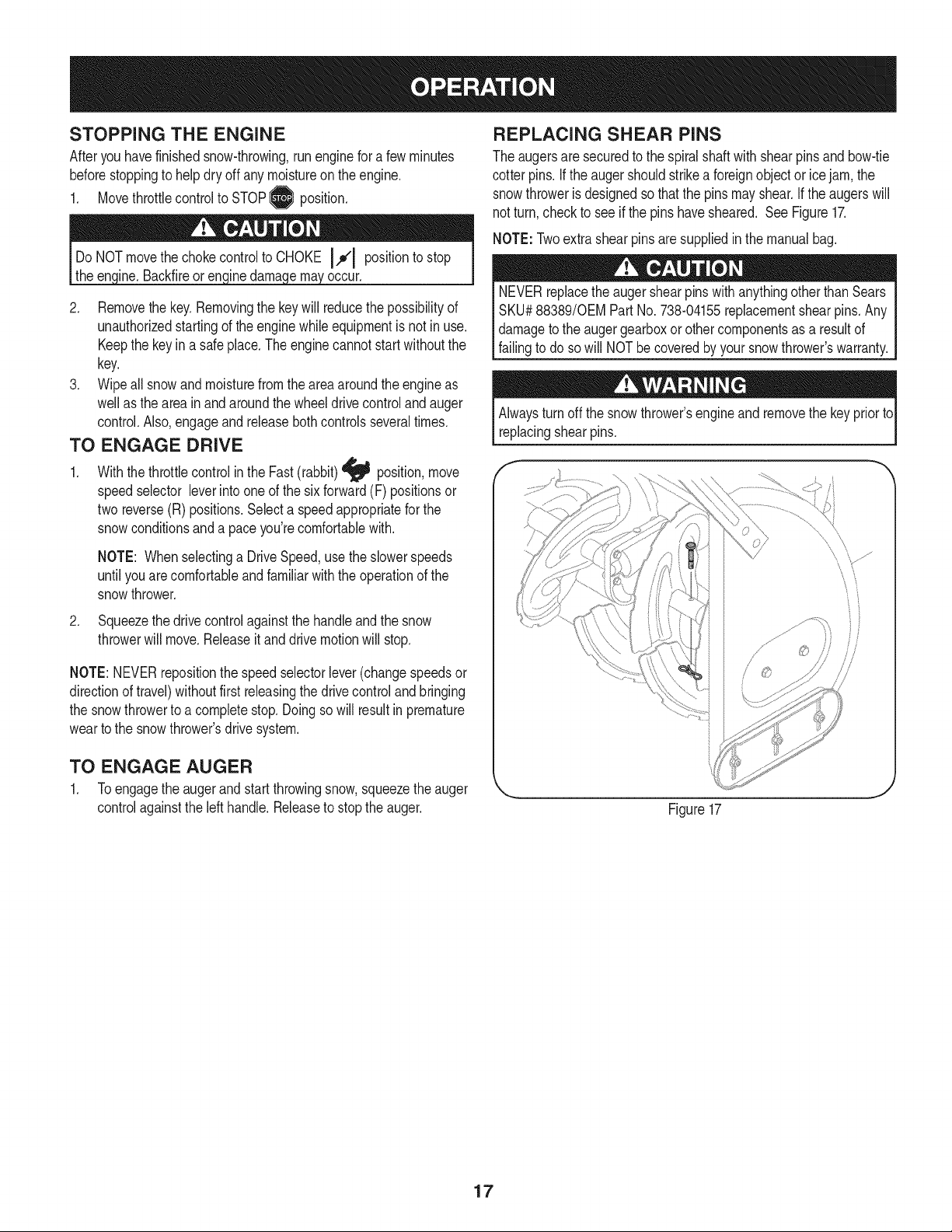
REPLACING SHEAR PiNS
The augersare securedto the spiralshaftwith shearpins andbow-tie
cotter pins.Ifthe augershouldstrikea foreignobjector icejam, the
snowthroweris designedso thatthe pinsmayshear.If the augerswill
notturn,checkto see if the pinshavesheared. SeeFigure17.
NOTE:Twoextrashearpinsaresuppliedin the manualbag.
NEVERreplacethe augershearpinswithanythingotherthan Sears
SKU#88389/0EM PartNo.738-04155replacementshearpins. Any
damageto the augergearboxorothercomponentsas a resultof
failingto do sowill NOTbecoveredbyyour snowthrower'swarranty.
Alwaysturn offthe snowthrower'sengineand removethe keypriorto
replacingshearpins.
\
Figure17
17
MAINTENANCE SCHEDULE
Beforeperforminganytypeof maintenance/service,disengageall
controlsand stoptheengine.Waituntilall movingpartshavecometo a
completestop.Removethekeyto preventunintendedstarting.Always
wearsafetyglassesduringoperationor whileperforminganyadjustments
orrepairs.
Followthe maintenanceschedulegivenbelow.This chart describes
serviceguidelinesonly.Usethe ServiceLog columnto keeptrackof
completedmaintenancetasks.To locate the nearest Sears Service
Centeror to scheduleservice,simplycontactSears at
1-800-4-MY-HOME®.
EachUse
1st5 -8 hours
25 hours
50 hours
Annuallyor 100hours
BeforeStorage 1. Fuelsystem
Underheavyloador in high temperatures
1. Engineoillevel
2. Looseormissinghardware
3. Unitandengine.
1. Engineoil
1. Engineoi11-
2. Controllinkagesand pivots
1. Engineoil
1. Sparkplug
= =
1. Check
2. Tightenor replace
3. Clean
1. Change
1. Change
2. Lubewithlightoil
1. Change
1. Cleanand re-gap,orelse replace
withnew plug.
1. Runengineuntilit stopsfrom lackof
fuel oradda gasolineadditiveto the
gas in thetank.
ENGINE MAINTENANCE
Checking Engine Oil
Beforelubricating,repairing,or inspecting,disengageall controlsand
stopengine.Waituntilallmovingpartshavecometo a completestop.
Removethekeyto preventunintendedfiringofthe engine.
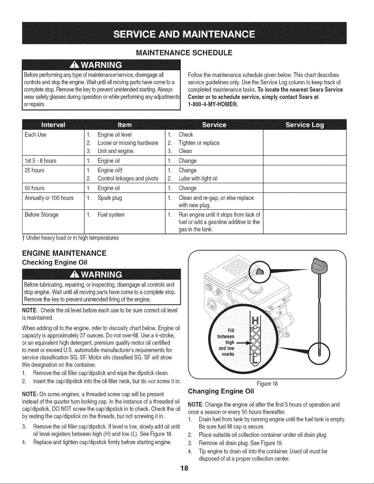
NOTE: Checktheoil levelbeforeeachuseto besurecorrectoil level
is maintained.
Whenaddingoilto the engine,referto viscositychart below.Engineoil
capacityis approximately37 ounces.Donot over-fill.Usea 4-stroke,
oran equivalenthighdetergent,premiumqualitymotoroil certified
to meetor exceedU.S.automobilemanufacturer'srequirementsfor
serviceclassificationSG, SR MotoroilsclassifiedSG, SFwill show
thisdesignationonthe container.
1. Removethe oil fillercap/dipstickand wipethe dipstickclean.
2. Insertthe cap/dipstickintotheoil filler neck,butdo not screwit in.
NOTE:On someengines,a threadedscrewcap will bepresent
insteadof thequarterturn lockingcap.In the instanceof a threadedoil
cap/dipstick,DO NOTscrewthecap/dipstickin to check.Checkthe oil
by restingthe cap/dipstickonthe threads,butnot screwingit in.
3. Removethe oil fillercap/dipstick,if levelis low, slowlyadd oiluntil
oil levelregistersbetweenhigh(H) andlow (L). SeeFigure18.
4. Replaceandtighten cap/dipstickfirmlybeforestartingengine.
Figure18
Changing Engine Oil
J
NOTE:Changethe engineoil afterthefirst 5 hoursof operationand
once a seasonor every50 hoursthereafter.
1. Drainfuel from tank by runningengine untilthefuel tank is empty.
Besurefuel fill capis secure.
2. Placesuitableoil collectioncontainerunderoil drain plug.
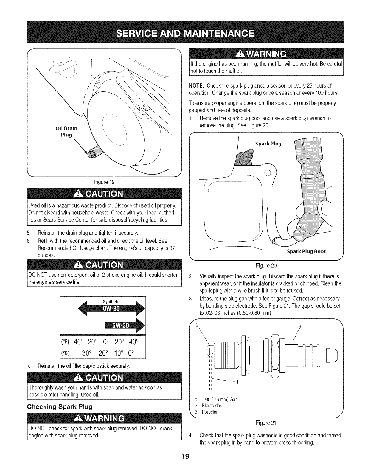
3. Removeoil drain plug.See Figure19.
4. Tip engineto drainoil intothe container.Usedoil mustbe
disposedof at a propercollectioncenter.
18
f
Oil Drain
Plug
Figure19
Usedoil is a hazardouswasteproduct.Disposeof usedoil properly.
Donotdiscardwith householdwaste.Checkwith yourlocalauthori-
tiesor SearsServiceCenterfor safedisposal/recyclingfacilities.
.
6.
Reinstallthe drainplugand tightenit securely.
Refillwiththe recommendedoil andcheckthe oil level.See
RecommendedOil Usage chart. The engine's oil capacity is 37
ounces.
if the enginehas beenrunning,the mufflerwill bevery hot.Becareful
not to touchthe muffler.
NOTE: Checkthe sparkplugonce a seasonor every25 hoursof
operation.Changethe sparkplug oncea seasonor every 100 hours.
Toensureproperengineoperation,the sparkplug mustbe properly
gappedandfree of deposits.
1. Removethe sparkplug bootand usea spark plugwrenchto
removethe plug.SeeFigure20.
Spark Plug
DONOTuse non-detergentoilor 2-strokeengineoil. Itcould shorten
the engine'sservicelife.
(°F}=40o =20o 0o 200 400
(°c) -30° -20° -10 ° 0°
7. Reinstallthe oil fillercap/dipsticksecurely.
Thoroughlywashyour handswithsoapand water as soonas
possibleafterhandling usedoil.
Checking Spark Plug
DO NOTcheckfor sparkwithsparkplug removed.DO NOTcrank
enginewithsparkplug removed.
Figure20
2. Visuallyinspectthe sparkplug. Discardthe sparkplugif thereis
apparentwear,or if the insulatoris crackedor chipped.Cleanthe
sparkplugwith a wire brushif it is to be reused.
3. Measurethe pluggap with a feelergauge.Correctas necessary
bybendingsideelectrode.SeeFigure21.Thegap shouldbe set
to .02-.03inches(0.60-0.80ram).
,'2 3
1..030 (.76 mm) Gap
2. Electrodes
k"_i Porcelain
Figure21
4. Checkthat the spark plugwasheris in good conditionandthread
the sparkplugin by hand to preventcross-threading.
19
5. Afterthe sparkplug is seated,tightenwitha spark plugwrenchto
compressthe washer.
NOTE:Wheninstallinga newsparkplug,tighten1/2-turnafter the
sparkplugseatsto compressthe washer.Whenreinstallinga used
sparkplug,tighten1/8-to 1/4-turnafter the sparkplug seatsto
compressthe washer.
hot andcan ine.
CARBURETOR ADJUSTMENT
Thecarburetoris notuseradjustable.ContactSearsParts& Repairfor
adjustment.
LUBRICATION
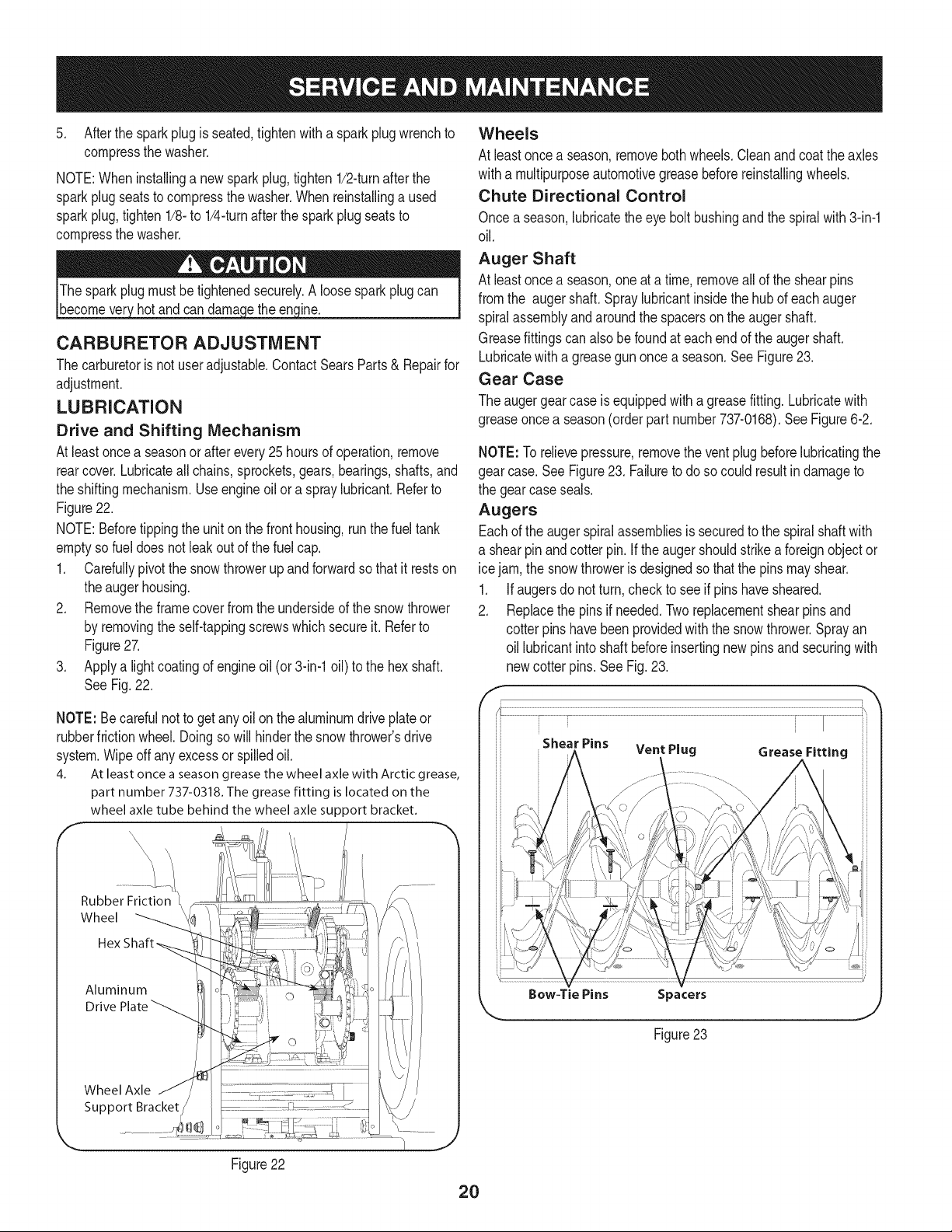
Drive and Shifting Mechanism
At leastoncea seasonor afterevery25 hoursof operation,remove
rearcover.Lubricateall chains,sprockets,gears,bearings,shafts,and
the shiftingmechanism.Useengineoil ora spraylubricant.Referto
Figure22.
NOTE:Beforetippingthe unit onthe front housing,run thefuel tank
emptyso fueldoes notleak outof thefuel cap.
1. Carefullypivotthe snowthrowerup and forwardso that it restson
theaugerhousing.
2. Removethe frame coverfrom the undersideof the snowthrower
by removingthe self-tappingscrewswhich secureit. Referto
Figure27.
3. Applya lightcoatingof engineoil (or3-in-1oil) to the hexshaft.
SeeFig. 22.
NOTE: Becarefulnotto get any oilon thealuminumdrive plateor
rubberfrictionwheel.Doingso will hinderthe snowthrower'sdrive
system.Wipeoff anyexcessor spilledoil.
4. At least once a season grease the wheel axle with Arctic grease,
part number 737-0318. The grease fitting is located on the
wheel axle tube behind the wheel axle support bracket.
Rubber Friction
Wheel
Aluminum
Drive
Wheel Axle
Support Bracket
Figure22
Wheels
At leastoncea season,removebothwheels.Cleanandcoatthe axles
witha multipurposeautomotivegreasebeforereinstallingwheels.
Chute Directional Control
Once aseason,lubricatethe eyebolt bushingandthe spiralwith 3-in-1
oil.
Auger Shaft
At leastoncea season,oneat a time, removeallof theshearpins
fromthe auger shaft.Spraylubricantinsidethe hubof eachauger
spiralassemblyandaroundthe spacerson the augershaft.
Greasefittingscan alsobe foundat each endof the augershaft.
Lubricatewitha greasegunoncea season.See Figure23.
Gear Case
The augergearcase is equippedwith a greasefitting.Lubricatewith
greaseoncea season(orderpart number737-0168).SeeFigure6-2.
NOTE: Torelievepressure,removethe ventplugbeforelubricatingthe
gearcase.See Figure23. Failureto doso could resultindamageto
the gearcase seals.
Augers
Eachof the augerspiralassembliesis securedto the spiralshaftwith
a shearpinandcotter pin.If the augershouldstrikeaforeignobjector
ice jam,the snowthroweris designedso thatthe pinsmay shear.
1. If augersdo not turn, checkto seeif pinshavesheared.
2. Replacethe pinsif needed.Tworeplacementshearpinsand
cotterpins havebeenprovidedwith the snowthrower.Sprayan
oil lubricantintoshaft beforeinsertingnewpinsand securingwith
newcotter pins.See Fig.23.
Shear Pins Vent Plug Grease Fitting
2O
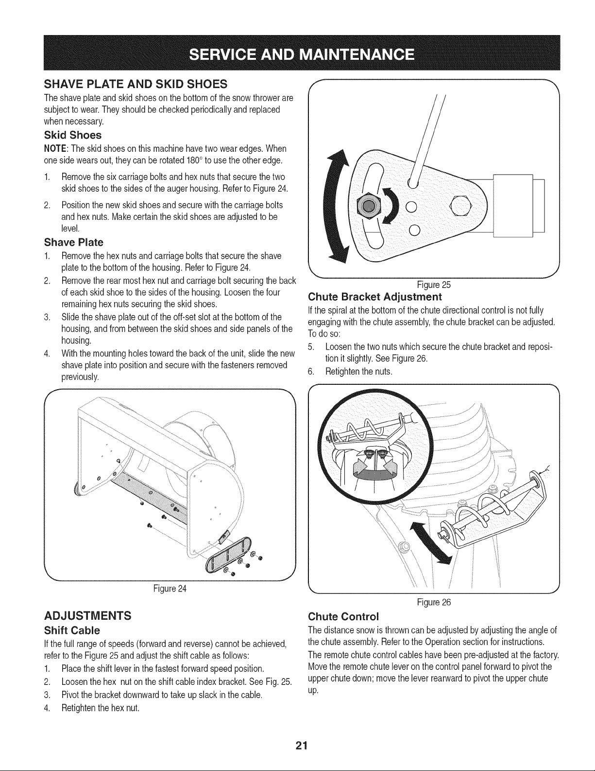
SHAVE PLATE AND SKiD SHOES
Theshaveplateand skidshoesonthe bottomof the snowthrowerare
subjectto wear.Theyshouldbe checkedperiodicallyand replaced
whennecessary.
Skid Shoes
NOTE:Theskidshoesonthismachinehavetwo wearedges.When
onesidewearsout, theycan be rotated1800to usethe otheredge.
1. Removethesix carriageboltsandhexnutsthatsecurethe two
skidshoesto the sidesof the augerhousing.Referto Figure24.
2. Positionthe new skid shoesand securewith the carriagebolts
andhex nuts.Makecertainthe skid shoesare adjustedto be
level.
Shave Plate
1. Removethehex nutsandcarriageboltsthatsecurethe shave
plateto the bottomof the housing.Referto Figure24.
2. Removethe rearmost hexnutand carriagebolt securingthe back
of eachskidshoeto the sidesof the housing.Loosenthefour
remaininghexnutssecuringthe skid shoes.
3. Slide theshaveplateout of the off-set slotat thebottomof the
housing,andfrom betweenthe skid shoesand side panelsof the
housing.
4. With the mountingholestowardthe back of the unit, slidethe new
shaveplateinto positionandsecurewith the fastenersremoved
previously.
f
ii
ii
ii
ii
ii
ii
ii
_J
Figure24
ADJUSTMENTS
Shift Cable
If thefull rangeof speeds(forwardandreverse)cannotbe achieved,
referto the Figure25 andadjustthe shiftcable as follows:
1. Placethe shiftleverin thefastestforwardspeedposition.
2. Loosenthe hex nuton the shiftcable indexbracket.SeeFig.25.
3. Pivotthe bracketdownwardto take up slack in the cable.
4. Retightenthehex nut.
k
J
Figure25
Chute Bracket Adjustment
Ifthe spiralat the bottomof thechutedirectionalcontrolis notfully
engagingwiththechute assembly,the chutebracketcan be adjusted.
Todo so:
5. Loosenthetwo nutswhich securethe chute bracketand reposi-
tion it slightly.SeeFigure26.
6. Retightenthenuts.
Figure26
Chute Control
The distancesnowis throwncanbe adjustedbyadjustingthe angleof
the chuteassembly.Referto the Operationsectionfor instructions.
The remotechutecontrolcableshavebeen pre-adjustedat the factory.
Movethe remotechuteleveron the controlpanelforwardto pivotthe
upperchutedown;movethe leverrearwardto pivotthe upperchute
up.
21
Wheel drive control
Referto the Adjustmentsectionof the Assemblyinstructionsto adjust
thewheeldrive control.Tofurthercheckthe adjustment,proceedas
follows:
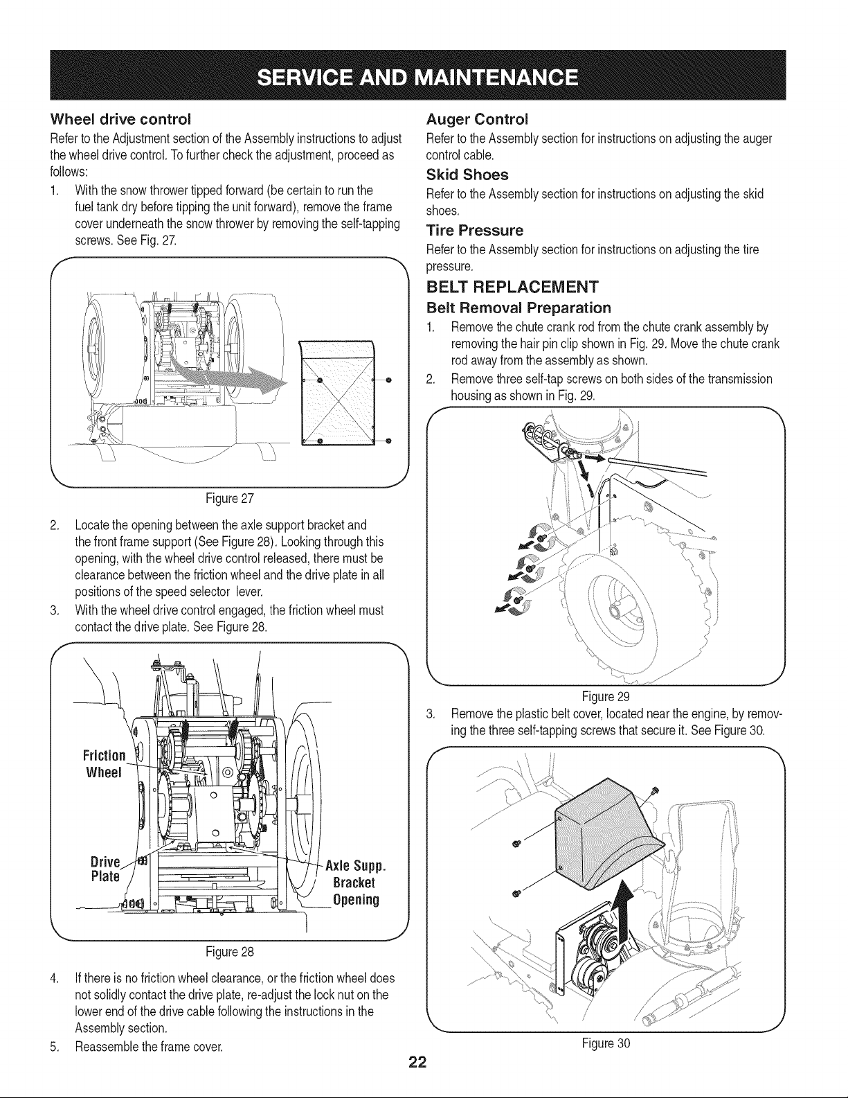
1. Withthe snowthrowertippedforward(be certainto runthe
fueltankdry beforetippingthe unitforward),removethe frame
coverunderneaththe snowthrowerby removingthe self-tapping
screws.SeeFig.27.
J
Figure27
2. Locatethe openingbetweenthe axle supportbracketand
thefrontframesupport(See Figure28). Lookingthroughthis
opening,withthe wheeldrivecontrol released,theremustbe
clearancebetweenthefrictionwheelandthe driveplatein all
positionsof the speedselector lever.
3. Withthe wheeldrivecontrolengaged,the frictionwheelmust
contactthedrive plate.SeeFigure28.
Drive -Axle Supp.
Plate Bracket
Opening
Figure28
4. If there isno frictionwheelclearance,or the frictionwheeldoes
not solidlycontactthe driveplate,re-adjustthe lock nuton the
lowerendof thedrive cablefollowingthe instructionsin the
Assemblysection.
5. Reassemblethe framecover.
Auger Control
Referto theAssemblysectionfor instructionson adjustingthe auger
controlcable.
Skid Shoes
Referto theAssemblysectionfor instructionson adjustingthe skid
shoes.
Tire Pressure
Referto theAssemblysectionfor instructionson adjustingthe tire
pressure.
BELT REPLACEMENT
Belt Removal Preparation
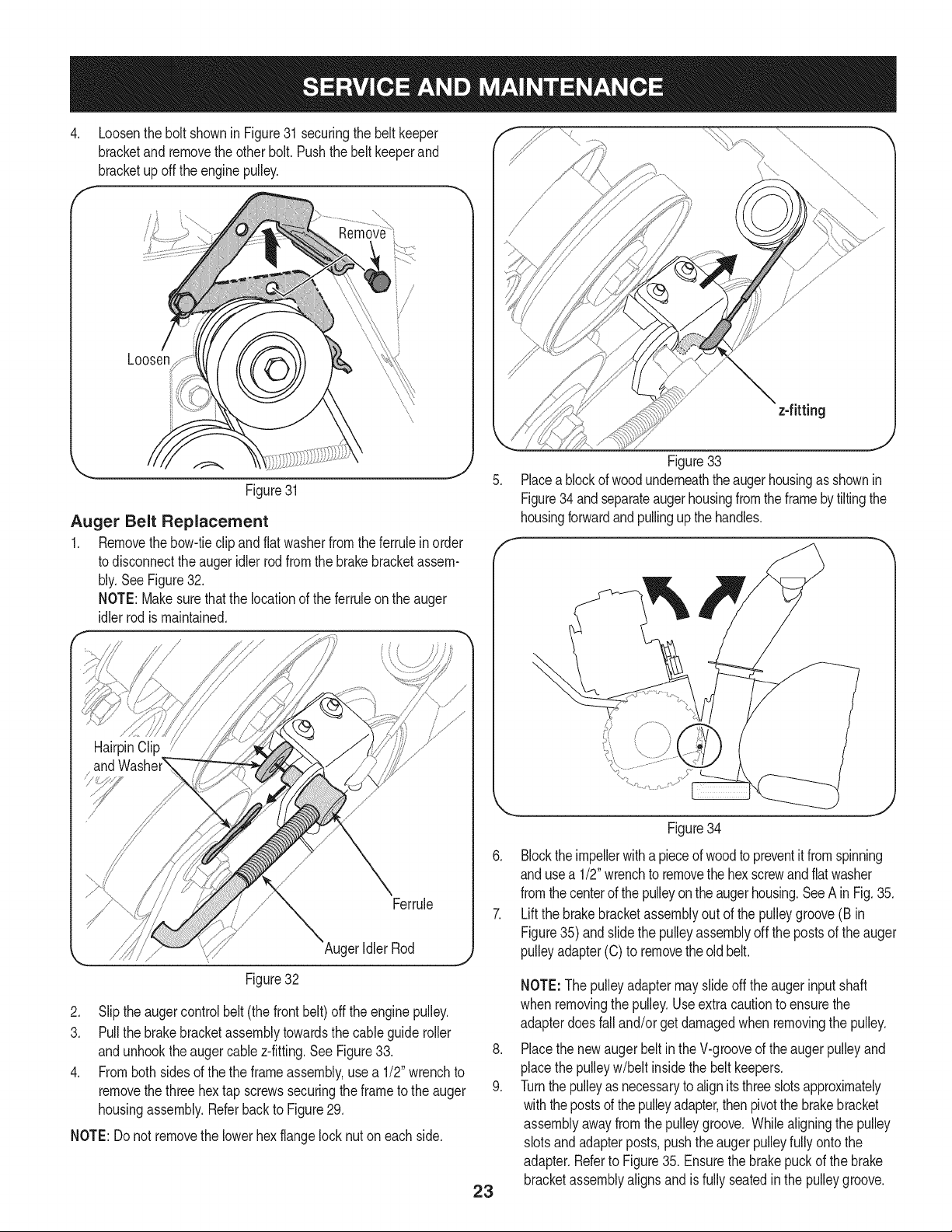
1. Removethe chutecrank rod from thechutecrankassemblyby
removingthe hairpinclip shownin Fig.29. Movethe chutecrank
rodawayfromthe assemblyas shown.
Removethreeself-tapscrewson bothsidesof the transmission
housingas shownin Fig.29.
Figure29
3. Removethe plasticbeltcover,locatednearthe engine,by remov-
ing thethreeself-tappingscrewsthatsecure it. See Figure30.
22
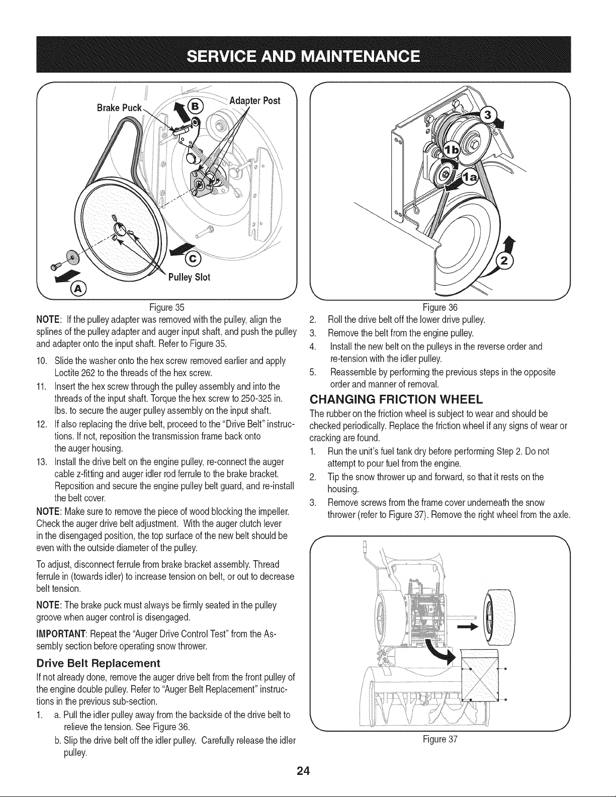
.Loosenthe bolt shownin Figure31securingthe beltkeeper
bracketandremovetheother bolt. Pushthe belt keeperand
bracketupoff the enginepulley.
Loosen
\
\
Figure31
Auger Belt Replacement
1. Removethebow-tieclip andflatwasherfromtheferrulein order
to disconnectthe augeridlerrod from the brakebracketassem-
bly.SeeFigure32.
NOTE:Makesurethatthe locationof the ferruleon the auger
idlerrodis maintained.
z-fitting
J
Figure33
Placeablockof woodunderneaththeaugerhousingas shownin
Figure34 andseparateaugerhousingfromtheframeby tiltingthe
housingforwardand pullingup the handles.
HairpinClip
Ferrule
AugerIdler Rod
Figure32
2. Slip the augercontrolbelt (thefront belt) off the enginepulley.
3. Pull the brakebracketassemblytowardsthe cableguide roller
andunhookthe augercable z-fitting.See Figure33.
4. Fromboth sidesof the the frameassembly,use a 1/2" wrenchto
removethe threehex tap screwssecuringthe frameto the auger
housingassembly.Referbackto Figure29.
NOTE:Do not removethe lowerhexflangelocknuton eachside.
Figure34
23
6. Blockthe impellerwith a pieceof woodto preventit fromspinning
andusea 1/2"wrenchto removethe hexscrewandflatwasher
fromthecenterof the pulleyontheaugerhousing.SeeA inFig. 35.
7. Lift the brakebracketassemblyout of the pulleygroove(B in
Figure35)andslide the pulleyassemblyoff the postsof the auger
pulleyadapter(C) to removethe oldbelt.
.
9.
NOTE:Thepulleyadaptermayslideoff the augerinputshaft
when removingthe pulley.Useextracautionto ensurethe
adapterdoesfalland/or get damagedwhen removingthe pulley.
Placethe newaugerbeltin the V-grooveof the augerpulleyand
placethe pulleyw/belt insidethebelt keepers.
Turnthe pulleyas necessaryto alignitsthreeslotsapproximately
withthepostsof thepulleyadapter,thenpivotthe brakebracket
assemblyawayfromthe pulleygroove. Whilealigningthe pulley
slotsandadapterposts,pushtheauger pulleyfully onto the
adapter.Referto Figure35. Ensurethebrakepuckof the brake
bracketassemblyalignsandis fully seatedin the pulleygroove.
!
pterPost
Brake
J
Figure35
NOTE: If the pulleyadapterwas removedwiththe pulley,alignthe
splinesof the pulleyadapterandaugerinputshaft, and pushthe pulley
andadapterontothe inputshaft. Referto Figure35.
10. Slidethe washerontothe hex screwremovedearlierandapply
Loctite262to thethreadsof the hex screw.
11. Insertthe hexscrewthroughthe pulleyassemblyandintothe
threadsof the inputshaft.Torquethe hex screwto 250-325in.
Ibs.to securethe augerpulleyassemblyon the inputshaft.
12. Ifalso replacingthe drivebelt, proceedto the "DriveBelt"instruc-
tions.If not,repositionthe transmissionframebackonto
theaugerhousing.
13. Installthedrive belton theenginepulley,re-connectthe auger
cablez-fittingandaugeridler rodferruleto the brakebracket.
Repositionand securethe enginepulleybelt guard,and re-install
the beltcover.
NOTE:Makesureto removethe pieceof woodblockingthe impeller.
Checkthe augerdrivebeltadjustment. Withthe augerclutchlever
inthe disengagedposition,thetop surfaceof the newbelt shouldbe
evenwiththeoutsidediameterof the pulley.
Toadjust,disconnectferrulefrombrakebracketassembly.Thread
ferrulein(towardsidler)to increasetensionon belt,orout to decrease
belttension.
NOTE:Thebrakepuckmustalwaysbefirmly seatedinthe pulley
groovewhenaugercontrolis disengaged.
IMPORTANT:Repeatthe "AugerDriveControlTest"fromthe As-
semblysectionbeforeoperatingsnowthrower.
Drive Belt Replacement
If notalreadydone,removethe augerdrivebelt fromthefrontpulleyof
theenginedoublepulley.Referto "AugerBeltReplacement"instruc-
tionsin the previoussub-section.
1. a. Pull the idler pulleyawayfrom the backsideof the drivebeltto
relievethetension.SeeFigure36.
b. Slipthe drivebelt offthe idlerpulley. Carefullyreleasethe idler
pulley.
J
Figure36
2. Rollthe drivebeltoff the lowerdrivepulley.
3. Removethe belt fromthe engine pulley.
4. Installthe newbelton the pulleysin the reverseorderand
re-tensionwiththe idler pulley.
5. Reassembleby performingthe previousstepsin theopposite
orderand mannerof removal.
CHANGING FRICTION WHEEL
The rubberonthe frictionwheelis subjectto wearandshouldbe
checkedperiodically.Replacethefrictionwheelif anysignsof wearor
crackingarefound.
1. Runthe unit'sfuel tankdry beforeperformingStep2. Donot
attemptto pourfuel fromthe engine.
2. Tip the snowthrowerupand forward,sothat it restsonthe
housing.
3. Removescrewsfrom theframe coverunderneaththe snow
thrower(referto Figure37). Removethe rightwheelfromthe axle.
e
Figure37
24
.
f
.
.
7.
f
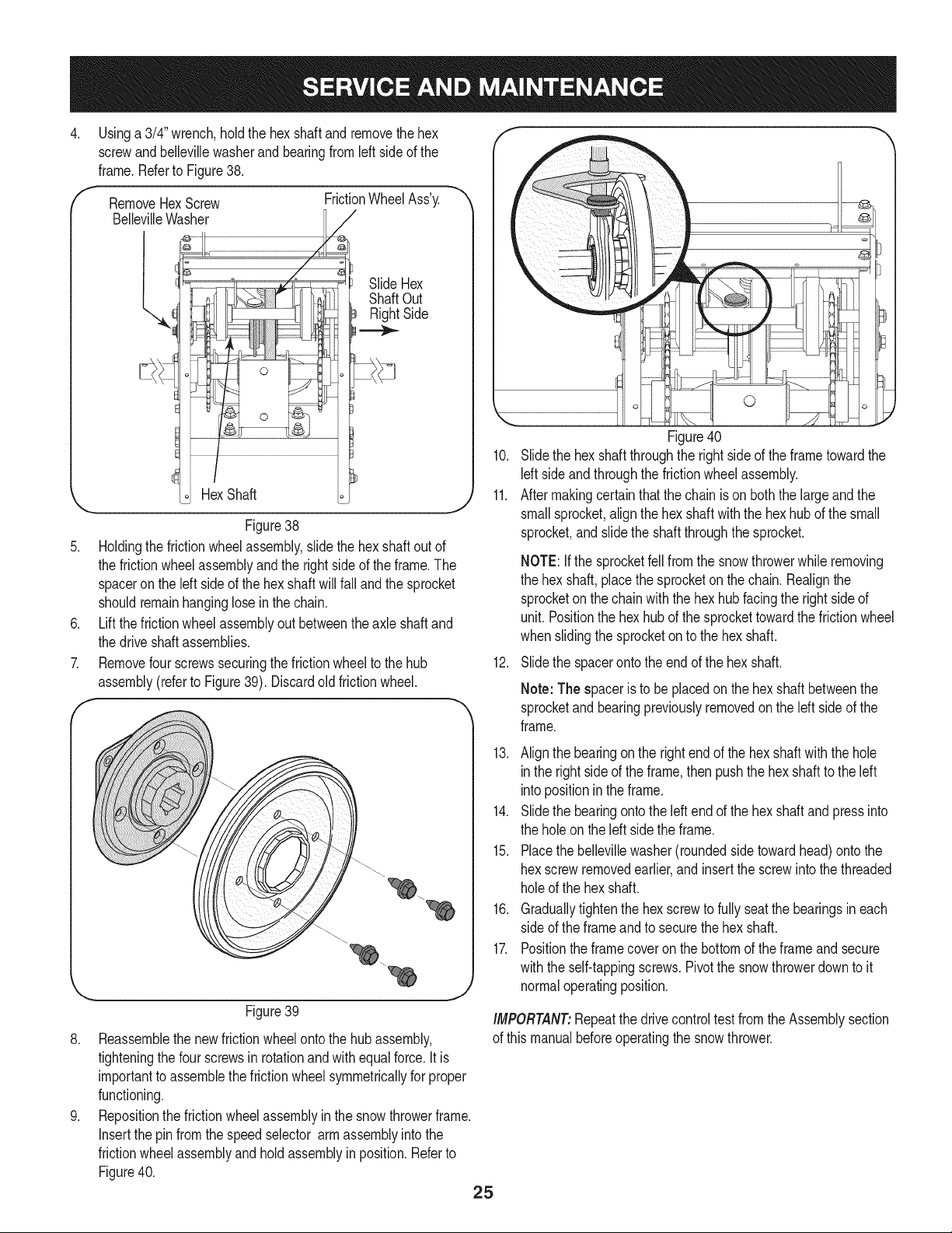
Usinga 3/4" wrench,holdthe hex shaftandremovethe hex
screwandbellevillewasherand bearingfromleft sideof the
frame.Referto Figure38.
RemoveHexScrew
BellevilleWasher
l,
FrictionWheelAss'y.
/
SlideHex
ShaftOut
RightSide
Figure38
Holdingthe frictionwheelassembly,slidethe hex shaftoutof
the frictionwheelassemblyandthe rightsideof theframe.The
spaceronthe left sideof the hex shaftwillfall andthe sprocket
shouldremainhanginglosein the chain.
Liftthe frictionwheelassemblyout betweenthe axle shaftand
the driveshaftassemblies.
Removefourscrewssecuringthe frictionwheelto the hub
assembly(referto Figure39). Discardoldfrictionwheel.
!!S i¸i¸i¸;i!!¸i¸:¸¸i¸¸i¸!_¸¸_!¸¸i¸¸¸¸¸¸¸¸¸¸¸¸¸'¸¸¸"i!i_i_!!!i!i;i!iiiiii!iiiii
f_L
¢-
_,,, J
Figure39
8. Reassemblethe newfrictionwheelontothe hub assembly,
tighteningthe fourscrewsin rotationandwithequalforce.It is
importantto assemblethefrictionwheelsymmetricallyfor proper
functioning.
9. Repositionthe frictionwheelassemblyin the snowthrowerframe.
Insertthe pinfromthe speedselector armassemblyintothe
frictionwheelassemblyandholdassemblyin position.Referto
Figure40.
25
0
Figure40
10. Slidethe hexshaft throughthe rightside of the frametowardthe
Idt sideand throughthe frictionwheelassembly.
11. Aftermakingcertainthatthe chainis on boththe largeandthe
smallsprocket,alignthe hex shaftwiththe hexhubof the small
sprocket,and slidethe shaftthroughthe sprocket.
NOTE:Ifthe sprocketfell fromthe snowthrowerwhile removing
the hex shaft,placethe sprocketonthe chain.Realignthe
sprocketonthe chainwith the hex hubfacing the rightsideof
unit.Positionthe hexhub of the sprockettowardthe frictionwheel
whenslidingthe sprocketon to the hexshaft.
12. Slidethe spacerontothe endof the hex shaft.
Note: The spaceris to be placedon the hexshaftbetweenthe
sprocketandbearingpreviouslyremovedon the left sideof the
frame.
13. Alignthe bearingonthe rightend of thehex shaftwith the hole
inthe rightside of the frame,then pushthe hexshaftto the left
intopositioninthe frame.
14. Slidethe bearingontothe leftend of the hex shaftand press into
the holeon theleft sidethe frame.
15. Placethe bellevillewasher(roundedside towardhead)ontothe
hexscrewremovedearlier,andinsertthescrewinto thethreaded
holeof the hex shaft.
16. Graduallytightenthe hexscrewto fullyseatthe bearingsineach
sideof the frameandto securethe hex shaft.
17. Positionthe framecoveron the bottomof the frameand secure
withthe self-tappingscrews.Pivotthe snowthrowerdownto it
normaloperatingposition.
iMPORTANT:Repeatthe drivecontroltestfromthe Assemblysection
of this manualbeforeoperatingthe snowthrower.
Ifthesnowthrowerwillnotbeusedfor30daysorlonger,orifitistheendofthesnowseasonwhenthelastpossibilityofsnowisgone,the
equipmentneedstobestoredproperly.Followstorageinstructionsbelowtoensuretopperformancefromthesnowthrowerformanymoreyears.
PREPARING ENGINE
Enginesstoredover30days need to be drainedof fuel to prevent
deteriorationandgumfrom forminginfuel systemor onessential
carburetorparts.If thegasolineinyourenginedeterioratesduring
storage,youmayneedto havethe carburetor,and otherfuel system
components,servicedor replaced.
1. Removeall fuel fromtank by runningengineuntil it stops. Donot
attemptto pourfuel fromthe engine.
2. Changethe engineoil.
3. Removesparkplug and pour approximately1 oz. (30 rnl) of clean
engineoil intothe cylinder.Pullthe recoilstarterseveraltimesto
distributetheoil, and reinstallthe sparkplug.
4. Cleandebrisfromaroundengine,andunder,around,and behind
muffler.Applya lightfilm of oil on anyareasthatare susceptible
to rust.
• Storein a clean,dry and wellventilatedarea awayfrom anyap-
pliancethatoperateswith a flame or pilotlight,suchas a furnace,
waterheater,or clothesdryer.Avoidany areawitha spark
producingelectricmotor,or wherepowertoolsareoperated.
Neverstoresnowthrowerwith fuel in tank indoorsor inpoorlyventi-
latedareas,wherefuel fumesmayreachan openflame,sparkor pilol
lightas ona furnace,waterheater,clothesdryer orgas appliance.
• If possible,avoidstorageareaswith high humidity.
• Keepthe enginelevelin storage.Tiltingcan causefuel or oil
leakage.
PREPARING SNOW THROWER
Whenstoringthe snowthrowerin anunventilatedormetal stor-
age shed,careshouldbetakento rustprooftheequipment.Using
a light oilor silicone,coattheequipment,especiallyanychains,
springs,bearingsandcables.
• Removealldirt fromexteriorof engineand equipment.
• Followlubricationrecommendations.
• Storeequipmentin a clean,dry area.
• Inflatethe tiresto the maximumPSi. Referto tiresidewall.
26

Enginefailsto start
Enginerunningerratically/
inconsistentRPM(huntingor
surging)
Excessivevibration
Lossof power
Unitfailsto propelitself
Unitfailsto dischargesnow
1. Chokecontrolnot in CHOKEposition.
2. Sparkplugwire disconnected.
3. Faultysparkplug.
4. Fueltank emptyor stalefuel.
5. Enginenot primed.
6. Keynot inserted.
7. Extensioncordnot connected(when
usingelectricstartbutton,on modelsso
equipped).
1. EnginerunningonCHOKE.
2. Stalefuel.
3. Wateror dirt in fuel system.
4. Over-governedengine.
1. Loosepartsor damagedauger.
1. Sparkplugwire loose.
2. Gascap vent hole plugged.
1. Drivecable in need of adjustment.
2. Drivebelt looseor damaged.
3. Wornfrictionwheel.
1. Chuteassemblyclogged.
2. Foreignobject lodgedin auger.
3. Augercablein needof adjustment.
4. Augerbelt looseordamaged.
5. Shearpin(s) sheared.
1. Chuteassembledincorrectly.
1. Movechokecontrolto CHOKEposition.
2. Connectwireto sparkplug.
3. Clean,adjustgap,or replace.
4. Filltank with clean,freshgasoline.
5. Primeengineas instructedin the OperationSection.
6. Insertkeyfully intothe switch.
7. Connectone end of the extensioncordto the electric
starteroutletandthe otherend to a three-prong
120-volt,grounded,ACoutlet.
1. Movechokecontrolto RUNposition.
2. Filltank with clean,freshgasoline.
3. Drainfueltank by runningengineuntil it stops. Refill
withfreshfuel.
4. ContactyourSearsParts & RepairCenter.
1. Stopengineimmediatelyand disconnectsparkplug
wire.Tightenall boltsand nuts.Ifvibrationcontinues,
haveunit servicedbya SearsParts& RepairCenter.
1. Connectandtightenspark plugwire.
2. Removeiceand snowfrom gascap. Be certainvent
holeis clear.
1. Adjustdrivecontrolcable. Referto Serviceand
Maintenancesection.
2. Replacedrive belt. Referto Serviceand Mainte-
nancesection.
3. Havefrictionwheelreplacedat a SearsParts &
RepairCenter.
1. Stopengineimmediatelyand disconnectsparkplug
wire.Cleanchuteassemblyand insideof auger
housingwithclean-outtoolor a stick.
2. Stopengineimmediatelyand disconnectsparkplug
wire.Removeobjectfromaugerwith clean-outtool
ora stick.
3. Adjustaugercontrolcable. Referto Assembly
section.
4. Replaceauger belt. Referto Serviceand Mainte-
nancesection.
5. Replacewith newshearpin(s).
Chutefailsto easily rotate 180 1. Disassemblechutecontroland reassembleas
degrees directedinthe Assemblysection.
NEED HORE HELP?
Yot,Fttfind. th_ answer a!ld mo_e on ma_age_y_ifeocom _ for free]
Find this and att your other product manua[s ontine.
Get answers from our team of home experts.
Get a personalized maintenance p[an for your home.
Find information and tools to he[p with home projects.
managemylife
b_e'_g_t_/_eyeu by Sea_s
27
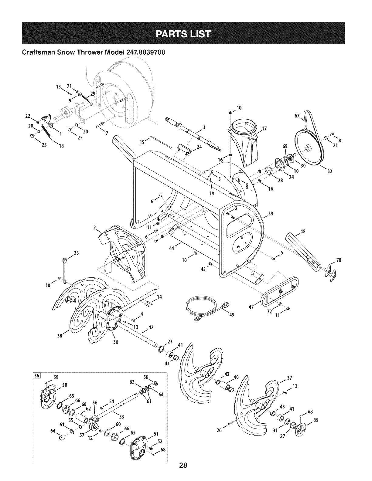
Craftsman Snow Thrower IViodel 247.8839700
22 /
!
®
/16j i
4
42
J
14
_/23 41 /_
28
72
43 41
48
21

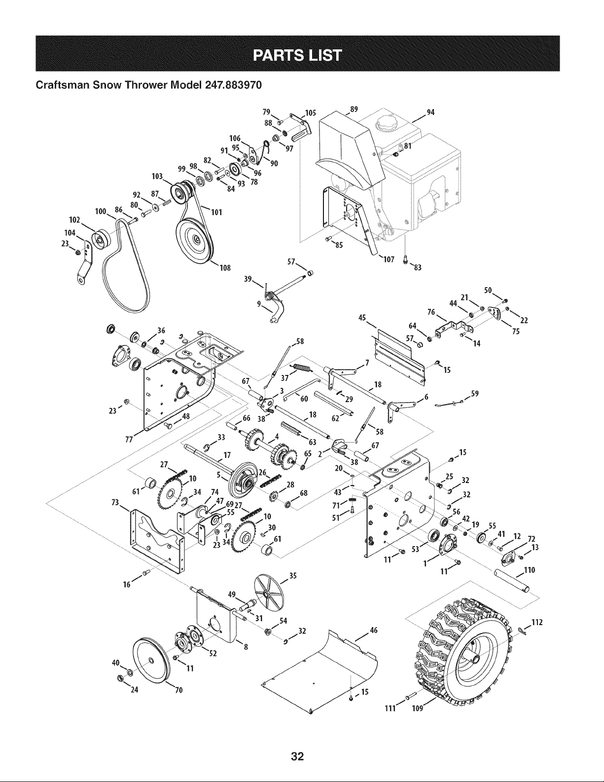
Craftsman Snow Thrower Model 247.883970
D = = 0 0
918-0281A Bracket Assy, Auger Brake
2. 684-0090B-0637 Impellar, 16"
3. 931-2643 Tool, Cleanout
4. 710-0376 Scr,Hex Cap, 5/16-18 x 1.00
5. L 710-04484 I Screw, 5/16-18 x .750
6. 710-0451 Screw, Carriage, 5/16-I 8 x .75
7. 710-04606A Screw, 5/16-18 x .4300
8. 710-1245B Screw, 5/16-24 x .875
9. 911-0677 Ferrule
I0. 712-04063 Nut, Flnge Lk, 5/16-18
11. 712-04065 Nut, Fig Lk, 3/8-16
12. 914-0135 Key, Woodruff, I/4 x 3/4
13. 714-04040 Pin, Bowtie Cotter
14. 915-0118 Pin, Spirol, 5/16 x 1.75
15. 725-0157 Tie, Cable
16. 926-04012 Nut, Push
17. 731-1696B Adapter, Chute, 6"
18. 732-0858 Spring, Extension
19. 936-0159 Washer, .349 x .879 x .063
20. 736-0174 Washer, .625 x .885 x .015
21. 736-0505 Washer, Flat, .34 x 1.50 x .150
22. 936-3008 Washer, .344 x .75 x .12
23. 736-3046A Washer, 1.01 x 1.86 x .06
24. 731-2635 Clip, Mounting
25. 938-0281 Screw, Shoulder, .625 x .17
26. 738-04155 Pin, Shear, .25 x 1.75
27. 741-0192 Bearing, Flange w/Flats
28. 941-04024 Bearing, Self Aligning
29. 747-0980A Rod, Auger Idler
30. 748-04067A Pulley, Adapter, .75 Dia.
31. 950-04020 Spacer, 1.004 x 1.375 x .25
32. 756-04244A Pulley, Auger Drive, 10.0
33. 790-00264A-0637 Bracket, Gear Box Support
34. 05244B Housing, Bearing
35. 784-0315A-0637 Housing, Bearing
36. 918-04514 Gear Box Assembly, Auger
D = I! tl
684-04151-4028 Spiral Assy, LH
38. 684-04152-4028 Spiral Assy, RH
39. 684-04214-0691 Housing, Auger - 33"
40. 731-05162 Spacer, 1.0 x 1.5 x 2
41. 731-05163 Spacer, 1.0 x 1.5 x 1
42. 938-04158 Axle, Spiral, 33"
43. 741-0494 Bushing, Flange, 1.051 x 1.16
44. 784-5714B-0637 Shave Plate
45. 710-3168 Bolt, Ca rriage, 3/8-16 x 1.0
46. 710-3034 Bolt, Ca rriage, 3/8-16 x 1.25
47. 731-06007 Shoe, Skid
48. 790-00181-0637 Drift Cutter
49. 929-0071A Extension Cord, 110V
50. 918-0246 Hsg Assy Auger RH (Inc. 65 & 66)
51. 918-0435 Hsg Assy Auger LH (Inc. 65 & 66)
52. 710-1260A Screw, LD, 5/16-18 x .750
53. 711-04714 Shf, Drive, Auger
54. 914-0126 Key, Hi Pro, 3/16 x 3/4
55. 716-0111 Ext, Ret, Ring
56. 917-0299 Gear, Worm, Dbl Thread
57. 917-1425 Gear, Worm, LH
58. 921-0145 Seal, Oil
59. 721-0325 Plug
60. 936-0266 Washer, Flat, 1.52 ID x 2.00D
61. 936-0291 Washer, Flat, .88 ID x .38 OD
62. 738-0275 Shf, Gea r, Worm
63. 741-0184 Brg, Th rust
64. 941-0217 Sleeve
65. 921-0146 Oil Seal
66. 741-0670 Flange Bearing
67. 954-04194A V Belt,4L x 44.60 Lg.
68. 937-3000 Lube Fitting, 3/16 #70
69. 736-0188 Washer, Flat, .78 x 1.49 x .08
70. 720-0284 Wing Knob
71. 712-3007 Jam Nut, 5/16-18
72. 736-0262 Washer, Flat, .385 x .870
29
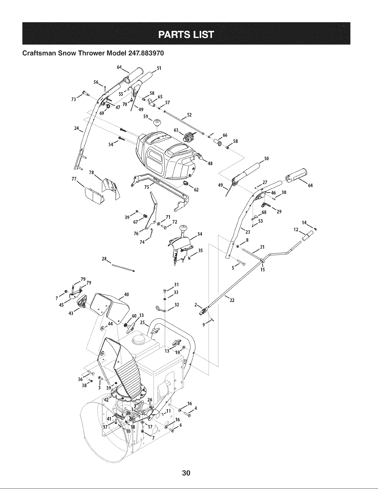
Craftsman Snow Thrower IViodel 247.883970
/
/
/
/
!
38
16
30
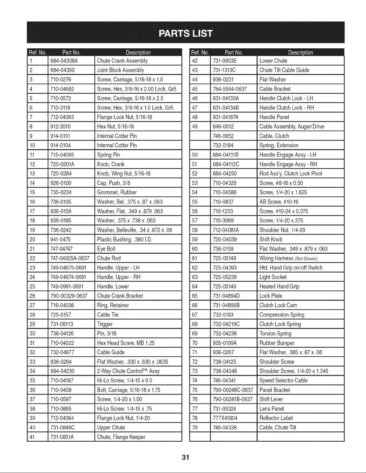
D _ O O
684-04308A ChuteCrankAssembly
2 _684-04350 _JointBlockAssembly
3 710-0276 Screw,Carriage,5/16-18x 1.0
4 710-04682 Screw,Hex,3/8-16x 2.00 Lock,Gr5
5 710-0572 Screw,Carriage,5/16-18x 2.5
6 710-3118 Screw,Hex,3/8-16x 1.0Lock,Gr5
7 712-04063 FlangeLockNut,5/16-18
8 912-3010 Hex Nut,5/16-18
9 914-0101 InternalCotterPin
10 914-0104 InternalCotterPin
11 715-04095 SpringPin
12 720-0201A Knob,Crank
13 720-0284 Knob,WingNut,5/16-18
14 926-0100 Cap,Push,3/8
15 735-0234 Grommet,Rubber
16 736-0105 Washer,Bel,.375x.87x.063
17 936-0159 Washer,Fiat,.349x.879.063
18 936-0185 Washer,.375x.738x.063
19 736-0242 Washer,Belleville,.34x.872x.06
20 941-0475 PlasticBushing,.380I.D.
21 747-04747 _Eye Bolt
22 747-04925A-0637 ChuteRod
23 749-04675-0691 Handle,Upper- LH
24 749-04674-0691 Handle,Upper- RH
25 749-0991-0691 Handle,Lower
26 790-00329-0637 ChuteCrankBracket
27 716-04036 Ring,Retainer
28 725-0157 CableTie
29 J 731-06113 l Trigger
30 738-04126 Pin, 3/16
31 710-04022 Hex HeadScrew,MB 1.25
32 732-04677 CableGuide
33 936-0264 FiatWasher,.330x.630x.0635
TM
34 984-04230 2-WayChuteControl Assy
35 710-04187 Hi-Lo Screw,1/4-15x 0.5
36 710-0458 Bolt,Carriage,5/16-18x 1.75
37 710-0597 Screw,1/4-20x 1.00
38 710-0895 Hi-Lo Screw,1/4-15x .75
39 712-04064 FlangeLockNut, 1/4-20
40 731-0846C UpperChute
41 731-0851A Chute,FlangeKeeper
D _ O
731-0903E LowerChute
43 731-1313C ChuteTiltCableGuide
44 936-0231 FiatWasher
45 784-5594-0637 CableBracket
46 631-04133A HandleClutchLock- LH
47 631-04134B HandleClutchLock- RH
48 931-04187A HandlePanel
49 646-0012 CableAssembly,Auger/Drive
746-0952 Cable,Clutch
732-0184 Spring,Extension
50 684-04111B HandleEngageAssy- LH
51 684-04112C HandleEngageAssy- RH
52 684-04250 RodAss'y,ClutchLock Pivot
53 710-04326 Screw,#8-16x 0.50
54 710-04586 Screw,1/4-20x 1.625
55 710-0837 ABScrew,#10-16
56 710-1233 Screw,#10-24x 0.375
57 710-3069 Screw,1/4-20x.375
58 712-04081A ShoulderNut, 1/4-20
59 720-04039 ShiftKnob
60 736-0159 FiatWasher,.349x.879x.063
61 725-05148 WiringHarness(NotShown)
62 725-04393 Htd.HandGripon/off Switch
63 725-05239 LightSocket
64 725-05149 HeatedHandGrip
65 731-04894D LockPlate
66 731-04896B ClutchLockCam
67 732-0193 CompressionSpring
68 732-04219C ClutchLockSpring
69 732-04238 TorsionSpring
70 935-0199A RubberBumper
71 936-0267 FiatWasher,.385x.87x.06
72 738-04125 ShoulderScrew
73 738-04348 ShoulderScrew,1/4-20x 1.345
74 746-04341 SpeedSelectorCable
75 790-00248C-0637 PanelBracket
76 790-00281B-0637 ShiftLever
77 731-05324 LensPanel
78 777X41804 ReflectorLabel
79 746-04338 Cable,ChuteTilt
31
Craftsman Snow Thrower Model 247.883970
106
91
100
102
104
23._
103
92
77
73
4O
24
36
27
108
34 74
11
"93 78
33
17
49
45
5O
44 21_
14
18
18
67
31 54
./32
111 10
125 32
32
56
19 55
72
32

Craftsman Snow Thrower IViodel 247.883970
|= o o
Housing,Bearing
Dogg,SteeringDrive,LH
Dogg,SteeringDrive,RH
05244B
2. 618-0279P
3. 618-0280P
4. 918-0282E ShaftAssembly,Steering
5. 918-04178 Assembly,FrictionWheel
718-04034 Wheel,Friction,Bonded
710-0896 Screw,HexWash
6. 684-0118B-0637 Bracket,AugerActuator
7. 684-0119B-0637 Bracket,DriveActuator
8. 684-04212-0637 Brkt, FrictionDriveSuprt.
9. 684-04229 RodAssembly,Shift
10. 684-04235 Sprocket,32T
11. 710-04484 TT Screw,5/16-18x .750
12. 710-0538 Screw,Hex CapLock,
13. 710-0599 HexScrew,1/4-20x .50
14. 710-0751 HexHeadScrew,1/4-20
15. 710-1652 Screw,HexWash.
16. 710-3001 Screw,Hex Cap,3/8-16
17. 911-04279 Shaft,HexDrive
18. 711-04605 Shaft,Actuator
19. 912-0116 Nut, HexInsertJamLock
20. 912-0138 Nut, Hex,1/4-28GR5
21. 712-04063 FlangeLockNut,5/16-18
22. 712-04064 FlangeLockNut, 1/4-20
23. 712-04065 FlangeLockNut,3/8-16
24. 912-0413 HexNut,5/8-18
25. 712-0717 Nut, Insert3/8-16
26. 713-0284 Chain,Endless,#41x 36L
27. 713-0286 Chain,#420x 40L
28. 913-04015 Sprocket,#41x lOT
29. 914-0104 Pin,InternalCotter
30. 914-0135 Key,Woodruff
31. 914-0388 Key,Hi-Pro,3/16 x 5/8
32. 916-0104 E-Ring
33. 716-0136 Ring,Retaining
34. 716-04048 Ring,Retainer
35. 917-0302 Plate,Drive
36. 726-0221 SpeedNut, .500
37. 932-0121 Spring,Extension
38. 932-0209 Spring,Extension
33
D= • Q _•
732-04385 TorsionSpring,.750I.D.x .968 Lg.
40. 936-0158 Washer,Lock,5/8
41. 736-0242 Wsh,Bell.,.34x.872x.06
42. 936-0864 Wash,.375x.812x.060
43. 936-0329 Washer,Lock,1/4
44. 936-3015 FiatWasher,.469x.875x.105
45. 790-00257-0691 Cover,UpperFrame
46. 790-00259-0691 Cover,LowerFrame
47. 937-3000 Fitting,Lube,3/16 Drive
48. 738-0143 Screw,Shldr.,.498x.34
49. 738-0279 Spindle,DrivePlate
50. 738-04184A ShoulderScrew,.368x.113,1/4-20
51. 738-0924A Screw,HexShldr.,1/4-28
52. 741-0163A Ass'y,Bearing/Housing
53. 941-04025 Bearing,Self Aligning
54. 741-04108 Bearing,HexFlange
55. 941-0563 Bearing,Ball
56. 741-0747 Bush,Fig, .5625x 1.375x .4375
57. 741-0748 Bush,Fig, .5 ID x .627OD
58. 746-04337A SteeringCable,35.97"Long
59. 946-0951A Cable,AugerIdler
60. 747-0973 Rod,Drive Clutch
61. 750-04703 Spcr.,1.0IDx 1.50OD
62. 750-04717 Spcr.,.51IDx 7.895Lg.
63. 750-04718 Spcr.,.51IDx 3.66Lg.
64. 750-04719 Spcr.,.5151IDx .750ODx .220
65. 750-05342 Spcr.,.566IDx .87 ODx .190
66. 750-05343 Spcr.,.566IDx .87 ODx 1.25
67. 750-0903B Spcr.,.514x.632x 2.44
68. 950-0997 Spacer,.675x 1.0x .23
69. 750-1302B Spcr,.6725x 1.125x 2.48
70. 756-04244A Pulley,Auger
71. 756-0625 Roller,Cable
72. 784-0404 BearingRetainingBracket
73. 784-0406A-0637 Bracket,FrameSupport
4, 784-0407-0637
75. 790-00217A-0637
76. 790-00218A-0637
7_ 790-00349-0691
78. 684-04169
Bracket,AxleSupport
SpeedSelectorPivotBracket
SpeedSelectorShift Bracket
TransmissionFrame
Idler PulleyAssembly
Continuedonfollowingpage
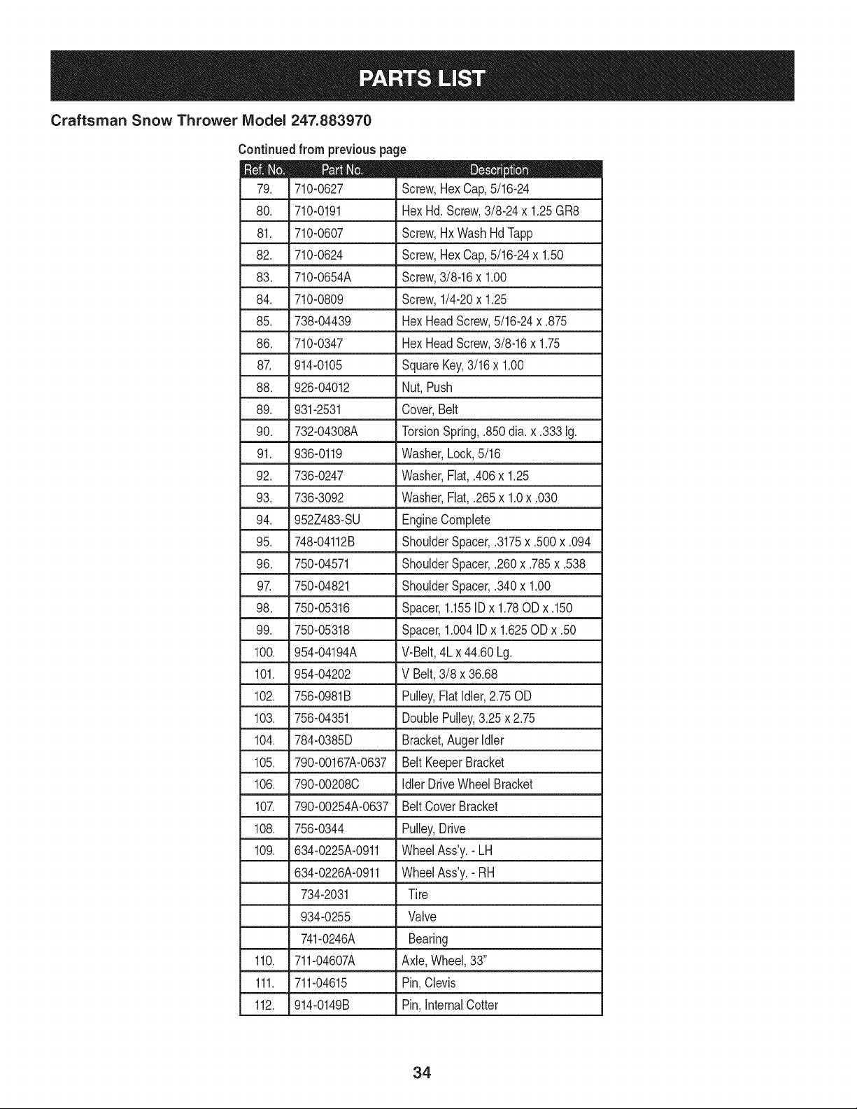
Craftsman Snow Thrower IViodel 247.883970
Continuedfrom previouspage
|= 0 =
710-0627 Screw,HexCap,5/16-24
80. 710-0191 Hex Hd. Screw,3/8-24x 1.25GR8
81. 710-0607 Screw,Hx WashHdTapp
82. 710-0624 Screw,Hex Cap,5/16-24x 1.50
83. 710-0654A Screw,3/8-16x 1.00
84. 710-0809 Screw,1/4-20x 1.25
85. 738-04439 HexHeadScrew,5/16-24x .875
86. 710-0347 Hex HeadScrew,3/8-16x 1.75
87. 914-0105 SquareKey,3/16 x 1.00
88. 926-04012 Nut, Push
89. 931-2531 Cover,Belt
90. 732-04308A TorsionSpring,.850dia.x .333 Ig.
91. 936-0119 Washer,Lock,5/16
92. 736-0247 Washer,Flat, .406x 1.25
93. 736-3092 Washer,Flat, .265x 1.0x .030
94. 952Z483-SU EngineComplete
95. 748-04112B ShoulderSpacer,.3175x.500x.094
96. 750-04571 ShoulderSpacer,.260x.785x.538
97. 750-04821 ShoulderSpacer,.340x 1.00
98. 750-05316 Spacer,1.155IDx 1.78ODx .150
99. 750-05318 Spacer,1.004IDx 1.625ODx .50
100. 954-04194A V-Belt,4Lx44.60 Lg.
101. 954-04202 V Belt,3/8 x 36.68
102. 756-0981B Pulley,FlatIdler,2.75OD
103. 756-04351 DoublePulley,3.25x 2.75
104. 784-0385D Bracket,AugerIdler
105. 790-00167A-0637 Belt KeeperBracket
106. 790-00208C Idler DriveWheel Bracket
107. 790-00254A-0637 BeltCover Bracket
108. 756-0344 Pulley,Drive
109. 634-0225A-0911 WheelAss'y.-LH
634-0226A-0911 WheelAss'y.-RH
734-2031 Tire
934-0255 Valve
741-0246A Bearing
110. 711-04607A Axle,Wheel,33"
111. 711-04615 Pin,Clevis
112. 914-0149B Pin,InternalCotter
34
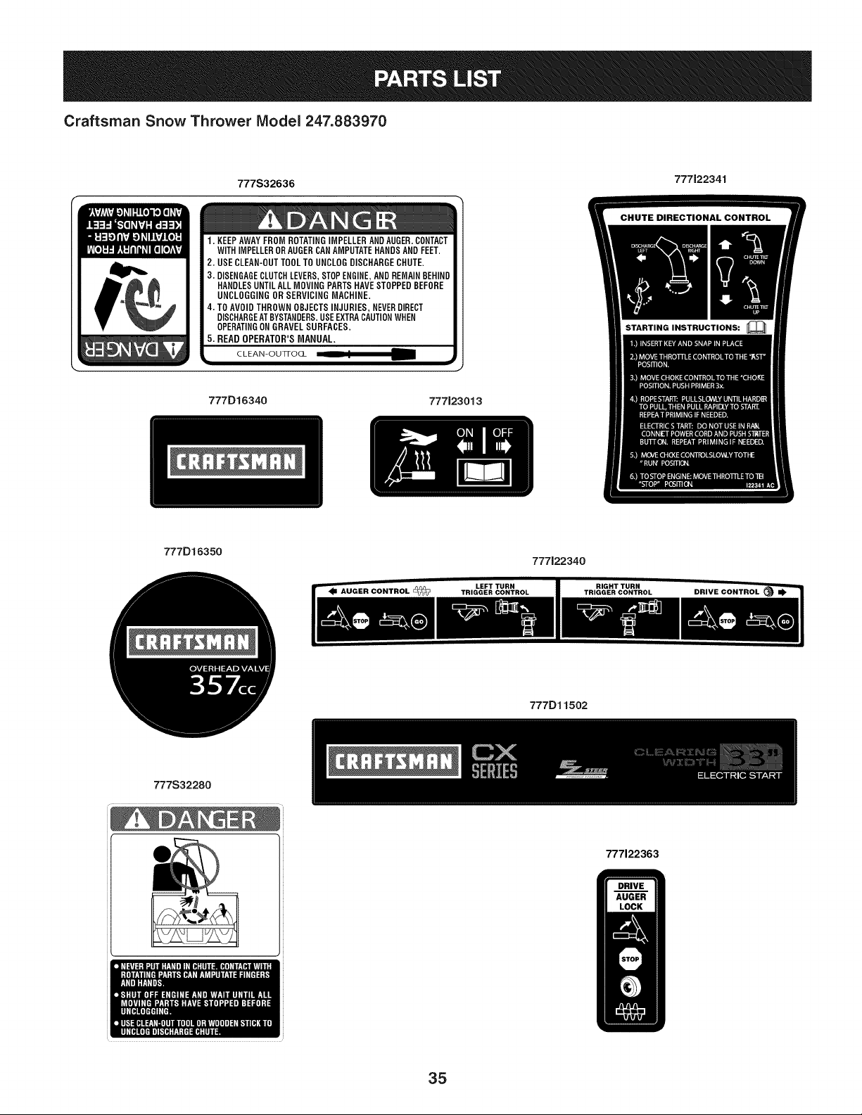
Craftsman Snow Thrower Model 247.883970
777S32636 777122341
1. KEEPAWAYFROMROTATINGIMPELLERANDAUGER.CONTACT
WITHIMPELLERORAUGERCANAMPUTATEHANDSANDFEET.
2. USECLEAN-OUTTOOLTO UNCLOGDISCHARGECHUTE.
3. DISENGAGECLUTCHLEVERS,STOPENGINE,ANDREMAINBEHIND
HANDLESUNTILALLMOVINGPARTSHAVESTOPPEDBEFORE
UNCLOGGINGOR SERVICINGMACHINE.
4. TOAVOIDTHROWNOBJECTSINJURIES,NEVERDIRECT
DISCHARGEATBYSTANDERS.USEEXTRACAUTIONWHEN
OPERATINGONGRAVELSURFACES.
5. READ OPERATOR'SMANUAL.
CLEAN=OUTFOCL
777D16340 777123013
STARTING INSTRUCTIONS:
777D16350
777122340
777Dl1502
777S32280
777122363
35

Craftsman Engine Model 483=SUB For Snow Model 247.883970
m
1
2
3
4
5
7
8
9
10
11
12
13
14
15
38
39
710-04915
951-11339
710-04915
951-10757
951-11595
731-05632
951-10637
951-11302
710-04914
951-11181
951-11321
710-04968
951-11338
712-05015
951-11311
710-04915
D = I! II
Bolt M6x12
MufflerShield
Bolt M6x12
ThrottleControlKnob
ControlPanel
Key
KeySwitchAssembly
ChokeKnob
Bolt M6xlO
ExhaustPipeShield
CarburetorHeatShield
Bolt M6x16
MufflerAssembly
Nut, M8
ThrottleControlAssembly
Bolt M6x12
36

Craftsman Engine Model 483-SUB For Snow Model 247.883970
m
129
130
131
132
133
134
135
135
136
137
138
139
147
a
b
C
d
e
f
g
h
i
I
a
o
m
x
--134
710-05392
710-05056
951-11315
951-11316
951-11223
951-14023A
951-10639A
951-11824
951-11304
951-11192
736-04477
712-05015
951-12760A
n/a
736-04638
710-05469
n/a
n/a
n/a
n/a
StudM6-8x100
StudM6-8x118
CarburetorIntakeGasket
CarburetorInsulator
CarburetorGasket
CarburetorAssembly
PrimerAssembly
PrimerBulb
HeaterBox
ChokeAssembly
LockWasher
NutM6
CarburetorRebuildKit
(Inc.i,j,p,q,r,s,t,u,v,x,z)
ChokeShaft
ChokeControlLeverWasher
FuelShutoffLeverScrew
ChokePlate
ThrottleShaft
ThrottlePlate
Gasket
m
h
I
J
k
I
m
n
0
P
q
r
s
t
U
V
W
X
Y
Z
aa
n/a
n/a
n/a
n/a
n/a
751-11991
951-11906
n/a
n/a
n/a
n/a
n/a
n/a
n/a
951-11970
n/a
951-11348
710-04945
951-11349
710-04938
D = O e
ThrottleShaftCover
IdleJetRivet
IdleJetAssembly
IdleSpeedAdjustingScrew
PrimerPipe
PrimerHose
PrimerHoseClamp
CarburetorBody
FloatPin
EmulsionTube
NickelPlatedBrassNeedleValve
MainJet
NeedleValveSpring
Float
FuelBowlGasket
FuelBowl
FuelBowlGasket
FuelBowlMountingBolt
FuelDrainPlugGasket
FuelDrainPlug
37

Craftsman Engine IViodel 483-SUB For Snow IViodel 247.883970
61
141
140
44
42
4O
I
43 42
144- GasketKit-Complete
145-GasketKit-External
146-CompleteEngine
49
38

Craftsman Engine IViodel 483=SUB For Snow IViodel 247.883970
m
4O
41
42
43
44
48
49
5O
51
52
53
54
55
56
57
58
59
60
61
62
64
65
66
67
951-11951
951-11952
951-11953
951-11954
951-12579
951-11956
951-11373
736-04453
714-04077
951-11958
951-11365
951-11342
951-10307
715-04102
715-04092
951-11959
951-11376
736-04545
951-11283
951-11577
951-14220
951-11340
951-11375
710-06061
710-06062
m = O Q
ConnectingRodAssembly
Piston
PistonPinSnap Ring
PistonPin
PistonRingSet
GovernorGear/ShaftAssembly
RadialBallBearing
FlatWasher
GovernorShaftClip
GovernorSeal
GovernorArm Shaft
CrankshaftKit
(Inc.49,54,55,65,81)
WoodruffKey
DowelPin 9 X 12
DowelPin7 X 14
CamshaftAssembly
CrankcaseCoverGasket
Washer
Oil FillPlugAssembly
O-Ring
CrankcaseCover
CrankcaseCoverKit
(Inc.49,59,60,64-68)
Oil Seal
Bolt M8x38
Bolt M8x45
m
68
69
7O
71
73
74
75
76
77
78
79
8O
81
140
141
143
144
145
146
710-06063
710-04968
951-11320
710-05349
951-11381
951-12073
951-11904
951-11971A
951-11341A
951-11328B
951-11350
736-04440
710-04906
951-11499
951-11968
951-11969
951-10641
951-11330A
951-11331
952Z483-SUB
D = W O
Bolt M8x35
Bolt M6x16
OilTubeSupportBracket
Bolt M6x8
Oil FillTubeO-Ring
Oil FillTubeAssembly
DipstickO-Ring
DipstickAssembly
CrankcaseKit
(Inc.49,52,77,81)
ShortBlockAssembly
(Inc.40-44,48-68,77-81,
102,105,106,108,110,111,
125,131,132,140,141)
Oil DrainPipe
DrainPipeWasher10X16X1.5
Oil DrainPlugBolt
OilSeal
BalanceGearAssembly
Bearing
Oil DrainAsm
GasketKit- Complete
(Inc.52,59,65,79,81,106,
108,125,131-133)
GasketKit- External
(Inc.79,108,125,131-133)
CompleteEngine
39
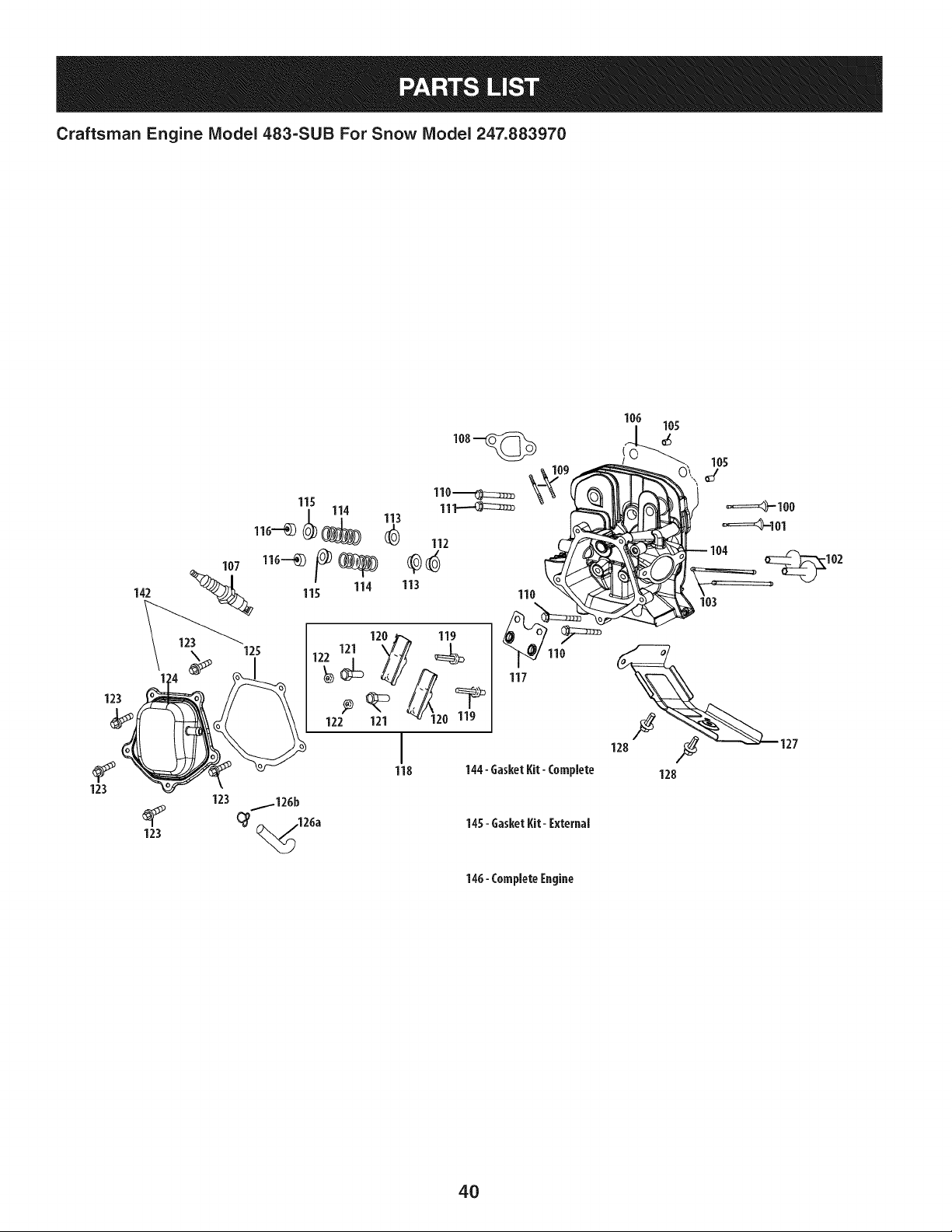
Craftsman Engine Model 483=SUB For Snow Model 247.883970
142
123
123
123
145- GasketKit- I:xternal
146- Complete[ngine
123
4O
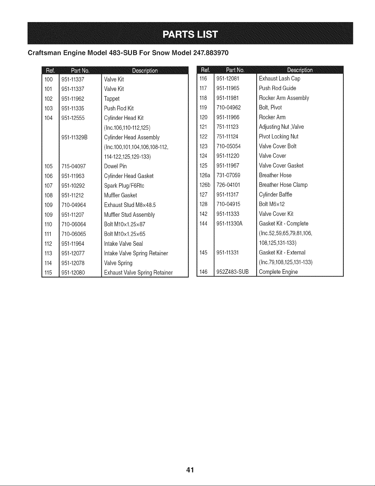
Craftsman Engine IViodel 483-SUB For Snow IViodel 247.883970
m
1CO
101
102
103
104
105
106
107
108
109
109
110
111
112
113
114
115
951-11337
951-11337
951-11962
951-11335
951-12555
951-11329B
715-04097
951-11963
951-10292
951-11212
710-04964
951-11207
710-06064
710-06065
951-11964
951-12077
951-12078
951-12080
D = O 0
ValveKit
ValveKit
Tappet
PushRodKit
CylinderHeadKit
(Inc.106,110-112,125)
CylinderHeadAssembly
(Inc.100,101,104,106,108-112,
114-122,125,129-133)
DowelPin
CylinderHeadGasket
SparkPlug/F6Rtc
MufflerGasket
ExhaustStudM8x48.5
MufflerStudAssembly
BoltM10x1.25x87
BoltM10x1.25x65
IntakeValveSeal
IntakeValveSpringRetainer
ValveSpring
ExhaustValveSpringRetainer
m
116
117
118
119
120
121
122
123
124
125
126a
126b
127
128
142
144
145
146
951-12081
951-11965
951-11981
710-04962
951-11966
751-11123
751-11124
710-05054
951-11220
951-11967
731-07059
726-04101
951-11317
710-04915
951-11333
951-11330A
951-11331
952Z483-SUB
D = O O
ExhaustLashCap
PushRodGuide
RockerArmAssembly
Bolt,Pivot
RockerArm
AdjustingNut,Valve
PivotLockingNut
ValveCoverBolt
ValveCover
ValveCoverGasket
BreatherHose
BreatherHoseClamp
CylinderBaffle
BoltM6x12
ValveCoverKit
GasketKit- Complete
(Inc.52,59,65,79,81,106,
108,125,131-133)
GasketKit- External
(Inc.79,108,125,131-133)
CompleteEngine
41

Craftsman Engine Model 483-SUB For Snow Model 247.883970
82
84
85
88
85
87
89
91
98
97
m
45
46
47
82
83
84
85
86
87
88
710-04965
951-11196
710-04967
951-11305
710-05350
951-12553
710-04969
710-04966
951-11186
951-12556
D = O
ScrewM4X55
ElectricStarter
Bolt M8x55
IgnitionCoilAssembly
IgnitionCoil Bolt
AlternatorAssembly
Bolt M6x30
Bolt M6x8
AlternatorWireClampBracket
Flywheel
m
89
90
91
92
93
95
96
97
98
951-11313
951-11314
712-04220
710-04968
710-04915
951-11211
951-14223
736-04455
710-04974
D = O
CoolingFan
StarterCup
FlywheelNut, M14x1.5
Bolt M6x16
Bolt M6x12
BlowerHousing
RecoilStarterAssembly
FlatWasher
Bolt M6xlO
42

Craftsman Engine IViodel 483=SUB For Snow IViodel 247.883970
m
16
17
18
19
2O
21
22
23
24
25
26
/.-25
%
26/
27
I
:}4 32
951-12533
951-11933
710-04970
750-05312
750-05313
951-11201
951-11319
951-11318
951-11351
710-04968
736-04452
D = O
FuelCap Assembly
FuelLevelIndicator
BoltM8x20
Bushing,Slot
Bushing,Rnd
FuelTankAssembly
FuelTankShroud
FuelTankMountingBracket
EngineShroud
BoltM6x16
Bush
m
27
28
29
30
32
33
34
35
36
37
951-11336
951-11700
710-04921
951-11182
712-04212
710-04908
951-11307
951-11306
951-11203
951-11309
m = O O
FuelLineKit
FuelHoseClamp
Bolt M8x14
FuelTankMountingBracket
FlangeNutM6
GovernorArm Bolt M6X21
GovernorArm
GovernorSpring
ThrottleReturnSpring
GovernorRod
43
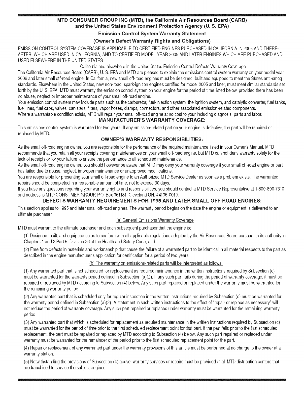
MTD CONSUMER GROUP INC (MTD), the California Air Resources Board (CARB)
and the United States Environment Protection Agency (U. S. EPA)
Emission Control System Warranty Statement
(Owner's Defect Warranty Rights and Obligations)
EMISSIONCONTROLSYSTEMCOVERAGEIS APPLICABLETOCERTIFIEDENGINESPURCHASEDINCALIFORNIAIN 2005 ANDTHERE-
AFTER,WHICHARE USEDINCALIFORNIA,ANDTO CERTIFIEDMODELYEAR2005 AND LATERENGINESWHICHARE PURCHASEDAND
USEDELSEWHEREIN THE UNITEDSTATES.
Californiaandelsewherein the UnitedStatesEmissionControlDefectsWarrantyCoverage
The CaliforniaAir ResourcesBoard(CARB),U.S. EPAandMTDarepleasedto explaintheemissionscontrolsystemwarrantyonyour modelyear
2006and latersmalloff-roadengine.In California,new smalloff-roadenginesmustbe designed,builtand equippedto meettheStatesanti-smog
standards.Elsewhereinthe UnitedStates,newnon-road,spark-ignitionenginescertifiedfor model2005and later,mustmeet similarstandardsset
forthby the U.S. EPA.MTDmustwarrantythe emissioncontrolsystemonyourenginefor the periodof timelistedbelow,providedtherehasbeen
noabuse,neglector impropermaintenanceof your smalloff-roadengine.
Youremissioncontrolsystemmayincludepartssuch as the carburetor,fuel-injectionsystem,the ignitionsystem,and catalyticconverter,fueltanks,
fuel lines,fuel caps,valves,canisters,filters,vaporhoses,clamps,connectors,and otherassociatedemission-relatedcomponents.
Wherea warrantableconditionexists,MTDwill repairyoursmalloff-roadengineat nocost to yourincludingdiagnosis,partsand labor.
MANUFACTURER'S WARRANTY COVERAGE:
Thisemissionscontrolsystemis warrantedfor twoyears.If anyemission-relatedpart onyourengineis defective,the part will berepairedor
replacedby MTD.
OWNER'S WARRANTY RESPONSIBILITIES:
As the smalloff-roadengineowner,youare responsibleforthe performanceof the requiredmaintenancelistedinyour Owner'sManual.MTD
recommendsthatyou retainall yourreceiptscoveringmaintenanceson yoursmalloff-roadengine,but MTDcan not denywarrantysolelyfor the
lackof receiptsor foryour failureto ensurethe performanceto allscheduledmaintenance.
As the smalloff-roadengineowner,youshouldhoweverbeawarethat MTDmaydenyyour warrantycoverageif yoursmalloff-roadengine or part
hasfaileddue toabuse,neglect,impropermaintenanceor unapprovedmodifications.
Youare responsiblefor presentingyour smalloff-roadengineto an AuthorizedMTDServiceDealeras soonas a problemexists.Thewarranted
repairsshouldbe completedina reasonableamountof time,notto exceed30 days.
Ifyou haveanyquestionsregardingyourwarrantyrightsand responsibilities,you shouldcontacta MTDService Representativeat 1-800-800-7310
andaddressis MTDCONSUMERGROUP,RO. Box361131,ClevelandOH,44136-0019.
DEFECTS WARRANTY REQUIREMENTS FOR 1995 AND LATER SMALL OFF-ROAD ENGINES:
Thissectionappliesto 1995andlater smalloff-roadengines.The warrantyperiodbeginson the datethe engineor equipmentis deliveredto an
ultimatepurchaser.
(a) GeneralEmissionsWarrantyCoverage_
MTDmustwarrantto the ultimatepurchaserandeachsubsequentpurchaserthat the engineis:
(1)Designed,built,andequippedsoas to conformwith all applicableregulationsadoptedby the Air ResourcesBoardpursuantto itsauthorityin
Chapters1and 2,Part 5, Division26 of the Healthand SafetyCode; and
(2) Freefromdefectsin materialsandworkmanshipthatcausethe failureof a warrantedpart to beidenticalin all materialrespectsto the partas
describedin theenginemanufacturer'sapplicationfor certificationfora periodof two years.
.(b)The warrantyonemissions-relatedpartswill be interpretedas follows:
(1)Anywarrantedpart thatis not scheduledfor replacementas requiredmaintenancein the writteninstructionsrequiredby Subsection(c)
mustbewarrantedfor the warrantyperioddefinedinSubsection(a)(2). If any such partfails duringthe periodof warrantycoverage,it mustbe
repairedor replacedby MTDaccordingto Subsection(4)below.Anysuch part repairedor replacedunder thewarrantymustbe warrantedfor
the remainingwarrantyperiod.
(2)Any warrantedpartthat is scheduledonlyfor regularinspectioninthe writteninstructionsrequiredby Subsection(c) must bewarrantedfor
thewarrantyperioddefinedin Subsection(a)(2).A statementinsuchwritteninstructionsto the effectof "repairor replaceas necessary"will
not reducethe periodof warrantycoverage.Anysuchpart repairedor replacedunderwarrantymustbe warrantedforthe remainingwarranty
period.
(3) Anywarrantedpartthat whichis scheduledfor replacementas requiredmaintenancein the writteninstructionsrequiredby Subsection(c)
mustbewarrantedfor the periodof timeprior to the first scheduledreplacementpointforthat part. If the part fails priorto thefirst scheduled
replacement,the part mustbe repairedor replacedby MTDaccordingto Subsection(4) below.Any suchpart repairedor replacedunder
warrantymustbewarrantedfor the remainderof the periodpriorto the first scheduledreplacementpointfor the part.
(4) Repairor replacementof any warrantedpartunderthewarrantyprovisionsof thisarticlemustbe performedat nochargeto the ownerat a
warrantystation.
(5) Notwithstandingthe provisionsof Subsection(4)above,warrantyservicesor repairsmustbe providedat all MTDdistributioncentersthat
arefranchisedto servicethe subjectengines.

(6)Theownermustnotbechargedfordiagnosticlaborthatleadstothedeterminationthatawarrantedpartisinfactdefective,providedthat
suchdiagnosticworkisperformedatawarrantystation.
(7)Theenginemanufacturerisliablefordamagestootherenginecomponentsproximatelycausedbyafailureunderwarrantyofanywarranted
part.
(8)Throughouttheengine'swarrantyperioddefinedinSubsection(a)(2),MTDwillmaintainasupplyofwarrantedpartssufficienttomeetthe
expecteddemandforsuchparts.
(9)Anyreplacementpartmaybeusedintheperformanceofanywarrantymaintenanceorrepairsandmustbeprovidedwithoutchargetothe
owner.SuchusewillnotreducethewarrantyobligationsofMTD.
(10)Add-onormodifiedpartsthatarenotexemptedbytheAirResourcesBoardmaynotbeused.Theuseofanynon-exemptedadd-onor
modifiedpartsshallbegroundsfordisallowingawarrantyclaimmadeinaccordancewiththisarticle.Theenginemanufacturershallnotbe
liableunderthisarticletowarrantfailuresofwarrantedpartscausedbytheuseofnon-exemptedadd-onormodifiedpart.
(c) MTDwill includea copyof the followingemissionwarrantypartslistwitheach newengine,usingthoseportionsof the listapplicableto the
e__&gine.
(1)FuelMeteringSystem
• Coldstart enrichmentsystem(soft choke)
,,Carburetorandinternalparts
• Fuel Pump
• FuelTank
(2)Air InductionSystem
• Aircleaner
• Intakemanifold
(3) IgnitionSystem
• Sparkplug(s)
• MagnetoIgnitionSystem
(4)ExhaustSystem
Catalyticconverter
• SAI (Reedvalve)
(5) MiscellaneousItemsUsedin AboveSystem
Vacuum,temperature, position,time sensitivevalvesand switches
Connectorsandassemblies
(6) Evaporativecontrol
• Fuel Hosecertifiedfor ARBevaporativeemissionof 2006.
• Fuel HoseClamps
Tetheredfuel cap
Carboncanister
• Vaporlines
GD0C-100174Rev.B

Look For Relevant Emissions Durability Period and
Air index information On Your Engine Emissions Label
Engines that are certified to meet the California Air Resources Board (CARB) Tier 2 Emission Standards must
display information regarding the Emissions Durability Period and the Air Index. Sears Brands Management
Corporation makes this information available to the consumer on our emission labels.
The Emissions Durability Period describes the number of hours of actual running time for which the engine is
certified to be emissions compliant, assuming proper maintenance in accordance with the Operating & Mainte-
nance Instructions. The following categories are used:
Moderate: Engine is certified to be emission compliant for 125 hours of actual engine running time.
Intermediate: Engine is certified to be emission compliant for 250 hours of actual engine running time.
Extended: Engine is certified to be emission compliant for 500 hours of actual engine running time.
For example, a typical walk-behind lawn mower is used 20 to 25 hours per year. Therefore, the Emissions
Durability Period of an engine with an intermediate rating would equate to 10 to 12 years.
The Air index is a calculated number describing the relative level of emissions for a specific engine family. The
lower the Air Index, the cleaner the engine. This information is displayed in graphical form on the emissions label.
After July 1,2000, Look For Emissions Compliance Period
On Engine Emissions Compliance Label
After July 1, 2000 certain Sears Brands Management Corporation engines will be certified to meet the United
States Environmental Protection Agency (USEPA) Phase 2 emission standards. For Phase 2 certified engines, the
Emissions Compliance Period referred to on the Emissions Compliance label indicates the number of operating
hours for which the engine has been shown to meet Federal emission requirements.
For engines less than 225 cc displacement, Category C = 125 hours, B = 250 hours and A = 500 hours.
For engines of 225 cc or more, Category C = 250 hours, B = 500 hours and A = 1000 hours.
This is ageneric representation of the emission label typically found on a certified engine.
FAMILYYBSXS.3192VA 274812
GDOC-100182Rev.B
46

Congratulations on making a smart purchase. Your new Craftsman® product is designed and
manufactured for years of dependable operation. But like all products, it may require repair
from time to time. That's when having a Repair Protection Agreement can save you money and
aggravation.
Here's what the Repair Protection Agreement* includes:
[] Expert service by our 10,000 professional repair specialists
[] Unlimited service and no charge for parts and labor on all covered repairs
[] Product replacement up to $1500 if your covered product can't be fixed
[] Discount of 25% from regular price of service and related installed parts not covered by the
agreement; also, 25% off regular price of preventive maintenance check
[] Fast help by phone - we call it Rapid Resolution - phone support from a Sears representative.
Think of us as a "talking owner's manual."
Once you purchase the Repair Protection Agreement, a simple phone call is all that it takes for you
to schedule service. You can call anytime day or night, or schedule a service appointment online.
The Repair Protection Agreement is a risk-free purchase. If you cancel for any reason during the
product warranty period, we will provide a full refund. Or, a prorated refund anytime after the
product warranty period expires. Purchase your Repair Protection Agreement today!
Some limitations and exclusions apply. For prices and additional information in the U.S.A.
call 1=800=827=6655.
*Coverage in Canada varies on some items. For full details call Sears Canada at 1=800=361=
6665.
Sears Installation Service
For Sears professional installation of home appliances, garage door openers, water heaters, and
other major home items, in the U.S.A. or Canada call 1=800=4=MY=HOME®.
47

Declaraci6n de garantia ............................ Pagina 48
Pr,_cticas operaci6n seguras ..................... Pagina 49
Montaje ...................................................... Pagina 53
Operaci6n .................................................. Pagina 58
Servicio y Mantenimiento .......................... Pagina 63
Almacenamiento fuera de temporada ....... Pagina 71
Soluci6n de problemas .............................. Pagina 72
Etiquetas de seguridad .............................. Pagina 7
Lista de piezas ........................................... Pagina 28
Acuerdo de protecci6n para reparaciones .... Pagina 79
NOmero de servicio ................................... atras pagina
CRAFTSMAN PROFESiONAL DE DOS AltOS DE GARANTiA
PORDOSANOSapartir deia fechade compra,esteproductoestAgarantizadocontracuaiquierdefectode materialo manode obra.Un
productodefectuosorecibirAla reparaci6no la sustituci6nsi la reparaci6nno estAdisponible.
Estagaranfiase aplicas61oparaun a_oa partirde la fechadecomprasi esteproductose hautilizadoalgunavez,mientrasquelaprestaci6nde
servicioscomercialeso si se alquilaa otra persona.
Paraobtenerinformaci6ndetalladacoberturade la garanfiaparaobtenerla reparaci6no sustituci6ngratuita,visiteel sitioweb:
www.craftsman.com.
Esta garantiacubre_nicamente losdefectos en rnateriales yrnano de obra. Lacobertura de garantiano incluye:
• Elementosreutilizablesquepuedengastarseporel uso normaldentrodel periodode garanfia,incluyendoperonolimitadoalas barrenas,
palasbarren&cortadoresde la deriva,zapatosantideslizantes,placade raspado,pasadoresde seguridad,la buj[a,el filtrodeaire,
cinturones,y el filtrode aceite.
• Los serviciosde mantenimiento,cambiosde aceite,o puestasa punto.
• NeumAticosde reemplazoo reparaci6nde pinchazoscausadosporobjetosexternos,talescomoclavos,espinas,toconeso vidrio.
• Neumaticoo ruedade repuestoo reparaci6nresultantesdel desgastenormal,accidenteo realfuncionamientoo mantenimiento.
• Reparacionesnecesariasdebidoal abusodel operador,incluyendoperonolimitadoa da_oscausadosporexcesode velocidaddel motor,
ode impactode objetosquedoblenla estructura,el ejedeltaladro,etc
• Las reparacionesnecesariasdebidoa la negligenciadel operador,incluyendoperono limitadoa, da_oseBctricosy mec_nicoscausados
porunalmacenamientoinadecuado,no utilizaci6nde la calidado cantidadde aceite de motoro falta de mantenimientodel equipode
acuerdoalas instruccionescontenidasenel manualdel operador.
• Del motor(sistemade combustible)de limpiezao reparacionesprovocadaspor un combustibleque se contaminadou oxidado(viejo).En
general,el combustibledebeser utilizadodentrode los30 d[assiguientesa lafecha de compra.
• Deterioroy desgastenormalde los acabadosexteriores,o reemplazode la etiquetadel producto.
Estagaranfiale otorgaderechoslegalesespec[ficos,y ustedtambi_npuedetenerotros derechosque var[andeestadoa estado.
Sears Brands Management Cot
Tipodeaceitedel motor:
Capacidadde aceitedel motor:
Capacidadde combustible:
Bujias:
Separaci6nde las bujias:
5W-30
37onzas
5cuartos
F6RTC(951-10292)
.020"to .030"
}oration, Hoffman Estates, IL 60179
N_mero de modelo ..........................................................
N_mero de serie..............................................................
Fechade eompra .............................................................
Registrearribael n_merodel modelo,el n_merode seriey la fecha
de compra
© Sears Brands,LLC
48
Lapresenciade este sfrnboloindicaque setrata de instrucciones
irnportantesde seguridadquese deben respetarpara evitar
poneren peligrosu seguridadpersonaly/o materialy lade otras
personas.Leay siga todaslas instruccionesde este manualantes
de poneren funcionarnientoestarn_.quina.Si no respetaestas
instruccionespodrfaprovocarlesionespersonales.Cuandoveaeste
sfrnbolo,ipresteatenci6na la advertencia!
PROPOSICION 65 DE CALIFORNIA
Elescapedel motordeeste producto,algunosde suscornponentes
y algunoscornponentesdel vehfculocontieneno liberan sustancias
qufrnicasqueel estado de Californiaconsideraque puedenproducir
c_.ncer,defectosde nacirnientouotrosproblernasreproductivos.
Estarn_.quinarue construidapara seroperadade acuerdocon
las reglasde seguridadcontenidaseneste manual.AI igualque
concualquiertipo deequipo rnotorizado,un descuidoo error por
partedeloperadorpuedeproducirlesionesgraves.Estarn_.quina
es capazde arnputarrnanosy piesy dearrojarobjetoscon gran
fuerza.Deno respetarlas instruccionesde seguridadsiguientesse
puedenproducirlesionesgraveso larnuerte.
Su responsabilidad--Restrinja el usode estarn_.quina
rnotorizadaa las personasque lean,cornprendany respetenlas
advertenciase instruccionesque aparecenen este manualy en la
rn_.quina.
iGUARDEESTASINSTRUCCIONES!
CAPACITACI6N
•Lea,entienday curnplatodaslas instruccionesincluidasen
la rn_.quinay enlos rnanualesantesdernontarlay utiNzarla.
Guardeestemanualen un lugarseguroparaconsultasfuturasy
peri6dicas,asf cornopara solicitarrepuestos.
•Leael ManualdelOperadory sigatodaslas advertenciase
instruccionesdeseguridad.Elfracasode hacerasf puedecausar
la heridaseriaal operadory/o personaspresentes.
•Farniliarfcesecontodoslos controlesy con el usoadecuado
delos rnisrnos.Sepa c6rnodetenerla rn_.quinay desactivarlos
controlesr_.pidarnente.
•No perrnitanuncaque los ni_osrnenoresde 14a_osutilicen
estarn_.quina.Los ni_osde 14a_osen adelantedebenleer y
entenderlas instruccionesde operaci6ny norrnasde seguridad
contenidasen este manual,y en la rn_.quinaydebenser entrena-
dosy supervisadosporun adulto.
•Nuncaperrnitaquelos adultosoperenesta rn_.quinasin recibir
antesla instrucci6napropiada.
•Losobjetosarrojadosporla rn_.quinapuedenproducirlesiones
graves.Planifiqueel patr6nen el que va a irarrojandonievepara
evitarque ladescargade materialse realicehacialos carninos,
los observadores,etc.
•Mantengaa losobservadores,ayudantes,rnascotasy ni_ospor
Io rnenosa 75piesde la rn_.quinarnientrasla rnisrnaest,.en
funcionarniento.Detengala rn_.quinasi alguienseacerca.
•Seaprecavidopara evitarpatinarseo caerseespecialrnente
cuandooperala rn_.quinaen reversa.
PR E PA RATIVO S
Inspeccionerninuciosarnenteel_.readondeutilizar_,el equipo.Saque
todoslos felpudos,peri6dicos,trineos,tablas,cablesy otros objetos
extra_oscon los quepodrfatropezaro quepodrfanser arrojadospor
labarrena/irnpulsor.
•Paraprotegerselosojos utilicesiernpreanteojoso antiparras
de seguridadrnientrasoperala rn_.quinao rnientrasla ajusta
o repara.Losobjetosarrojadosquerebotanpuedenproducir
lesionesocularesgraves.
•Nooperelarn_.quinasin la vestirnentaadecuadaparaestaral
airelibreen invierno.No utilicealhajas,bufandaslargasu otras
prendassueltasquepodrfanenredarseen las partes rn6viles.
UtiNceun calzadoespecialparasuperficiesresbaladizas.
•Useun prolongadory untornacorrientede tres cables con
conexi6na tierraparatodaslas rn_.quinascon rnotoresde
encendidoel_ctrico.
•Ajustela alturade lacaja deltornacorrientepara Nrnpiarla grava
o las superficiescon piedrastrituradas.
•Desengranetodaslas palancasde controlantesde arrancarel
motor.
•Nuncaintenterealizarajustesrnientrasel motorest,.en rnarcha
exceptoen los casosespecfficarnenterecornendadosen el
manualdeloperador.
•Dejequeelmotory la rn_.quinase adaptena laternperatura
exteriorantesde cornenzara sacarla nieve.
49
Manejo seguro de la gasolina
Paraevitarlesionespersonales0 daSosrnaterialestengarnucho
cuidadocuandotrabajecon gasolina.Lagasolinaes surnarnente
inflarnabley sus vaporespuedencausarexplosiones.Si se derrarna
gasolinaencirna0 sobrela ropase puedelesionargravernenteya que
se puedeincendiar. L&vesela piely c&rnbiesede ropade inrnediato.
• Utilices610los recipientespara gasolinaautorizados.
• Apaguetodos los cigarrillos,cigarros,pipasy otras fuentesde
cornbusfi6n.
• Nuncacarguecombustibleen la rn&quinaen un espaciocerrado.
• Nuncasaquela tapadel combustibleni agreguecombustible
rnientrasel motorest&caliente0 en rnarcha.
• Dejeque el motorse enfrieporI0 rnenosdos rninutosantesde
volvera cargarcombustible.
• Nuncallene en excesoel dep6sitode combustible.Lleneel
tanquea no rn&sde1/2pulgadapor debajode la basedel cuello
de Ilenadodejandoespaciopara la dilataci6ndeIcombustible.
• Vuelvaa colocarla tapade la gasoiinay aj_stelabien.
• Lirnpieel combustibleque se hayaderrarnadosobreel motory el
equipo.Trasladela rn&quinaa otra zona. Espere5 rninutosantes
deencenderel motor.
• Nuncaalrnacenela rn&quina0 el recipientede combustibleen
unespaciocerradodonde hayafuego,chispas0 luz piloto(por
ejernplo,hornos,calentadoresde agua,calefactores,secadores
de ropa,etc.).
• Dejeque la rn_.quinase enfrieporIo rnenos5 rninutosantesde
guardarla.
• NuncaIlenelos recipientesen el interiorde un vehiculoo carni6n
ocaja de rernolquecon recubrirnientospl_.sticos.Coloque
siernprelos recipientesen el pisoy lejosdelvehiculoantesde
Ilenarlos.
• Si es posible,retireel equipoa gasolinadel carni6no rernolque
y II_neloen el suelo.Siestonoes posible,Ileneel equipoen un
rernolquecon contenedorport_.til,envez de desdeuna boquilla
dispensadoradegasolina.
• Mantengala boquilladispensadoraen contactocon el hordedel
dep6sitode combustibleo con la aberturadel recipienteen todo
rnornento,hastaterrninarlacarga. No utiliceun dispositivode
apertura/cierrede boquilla.
FUNCIONANIIENTO
•No pongalas rnanoso los piescercadelas piezasrotatorias,
en lacajade la barrena/irnpulsoro en el rnontajedel canalde
descarga.Hacercontactocon piezasgiratoriaspuederesultaren
laarnputaci6ndernanoso pies.
• La palancade controlde la barrena/irnpulsores un dispositivo
de seguridad.Nuncaevitesu funcionarniento.De hacerlola
operaci6nde la rn_.quinaes riesgosay puedeocasionarlesiones.
• Las palancasde control debenfuncionarbien en arnbasdirec-
cionesy regresarautorn_.ticarnentea la posici6nde desengrane
cuandose lassuelta.
• Nuncaoperela rn_.quinasi faltaun rnontajedel canalo si el
rnisrnoest,.daSado.Mantengatodos losdispositivosde seguri-
daden su lugary enfuncionarniento.
• Nuncaenciendaelmotor en espacioscerradoso en una zona
con pocaventilaci6n.Elescapedel motorcontienernon6xidode
carbono,ungas inodoroy letal.
• Noutilicela rn_.quinabajola influenciadel alcoholo las drogas.
• Elsilenciadory el motorse calientany puedencausarquernadu-
ras.Nolos toque.Mantengaa los niSosalejados.
• Seasurnarnenteprecavidocuandoopere la rn_.quinasobreuna
superficiecon gravaocuandola cruce.Mant_ngasealerta porsi
se presentanpeligrosocultoso tr_.nsito.
• Tengacuidadocuandocarnbiede direcci6no cuandoopere
la rn_.quinaenpendientes.Nouse la rn_.quinaen pendientes
pronunciadas.
• Planifiqueel patr6nen el que va air arrojandonieveparaevitar
que ladescargade materialse produzcahacialas ventanas,
las paredes,losautorn6viles,etc.y evitarasi posiblesdaSos
rnaterialeso lesionesproducidasporlos rebotes.
• Nuncadirijala descargahacialos niSos,los observadoreso las
rnascotasni dejeque nadiese paredelantede la rn_.quina.
• Nosobrecarguelacapacidadde la rn_.quinatratandode sacarla
nievernuyr_.pidarnente.
• Nuncaopereestarn_.quinasin buenavisibilidado ilurninaci6n.
Siernpredebeestar segurode que est,. bien afirrnadoy su-
jetandofirrnernentelas rnanijas.Carnine,nuncacorra.
• Corte la corrientea la barrena/irnpulsorcuandotransportela
rn_.quinao cuandolarnisrnano est,. en uso.
• Nuncaoperela rn_.quinaaalta velocidadde desplazarniento
sobresuperficiesresbaladizas.Mirehaciaabajoy haciaatr_.sy
tengacuidadocuandovayarnarchaatr_.s.
• Si la rn_.quinacornenzaraa vibrarde rnaneraanorrnal,detengael
motor,desconecteel cablede labujia y p6ngalade rnaneraque
hagarnasacontra el motor.Inspeccionela rn_.quinarninuciosa-
rnenteparaver si est,.daSada.Reparetodos los daSosantesde
encendery operarla rn_.quina.
• Desengranetodaslas palancasde controly detengaelmotor
antesde dejar la posici6nde operaci6n(detr_.sdelas rnanijas).
Espereaque la barrena/irnpulsorse detengapor cornpleto
antesde destaparel rnontajedel canalo realizarajustese
inspecciones.
• Nuncapongalas rnanosenlas aberturasde descargao de
recolecci6n.Utilicesiernprela herrarnientade lirnpiezaque se
adjuntaparadestaparla aberturadedescarga.Nodestapeel
rnontajedelcanal rnientrasel motorest,.en funcionarniento.
Antesde destaparlo,apagueel motory perrnanezcadetr_.sde las
rnanijashastaque todaslas partesrn6vilesse hayandetenido.
• Uses61ounionesy accesoriosaprobadospot el fabricante(por
ejernplo,pesasparalas ruedas,cadenaspara los neurn_.ticos,
cabinas,etc.). Paraobtenerrn_.sinforrnaci6nacercadeestos
ternas,Ilarneal 1-800-469-4663.
5O

• Paraencenderel motor,jale de la cuerdalentarnentehasta que
sientaresistencia,luegojale r_.pidarnente.El replieguer_.pidode
la cuerdade arranque(tensi6nde retroceso)le jalar_,la rnanoy
el brazohaciael motorrn_.sr_.pidode Io queustedpuedesoltar.
El resultadopuedenserhuesosrotos,fracturas,hernatornaso
esguinces.
• Si se presentansituacionesqueno est_.nprevistasen este
manual,seacuidadosoy use el sentidocornOn.
• Para pedirrepuestoso serviciohorariopara este producto,Ilarne
a 1-800-469-4663.
MANTENIMIENTO Y ALMACENAMIENTO
•Nuncaalterelos dispositivosde seguridad.Controleperi6dica-
rnentequefuncionencorrectarnente.Rernitasealas secciones
demantenirnientoy ajustede este manual.
• Antesde realizarla lirnpieza,repararo revisarla rn_.quina,
desengranetodas laspalancasde controly detengael motor.
Esperea quela barrena/irnpulsorse detengapor cornpleto.
Desconecteel cablede la bujfay p6ngalohaciendornasacontra
el motorparaevitarquese enciendaaccidentalrnente.
• Controlefrecuenternenteque todos lospernosy tornillosest_n
bienajustadosparacornprobarque la rn_.quinase encuentra
encondicionessegurasde funcionarniento.Adern_.s,hagauna
inspecci6nvisual de larn_.quinaparaverificarsi est,. da_ada.
• No carnbiela configuraci6ndel reguladordel motorni acelere
dernasiadoel rnisrno.El reguladordel motorcontrolala velocidad
rn_.xirnaseguradefuncionarnientodel motor.
• Las placasde raspadoy las zapatasantideslizantesque se
usancon la rn_.quinaquitanievese desgastany se da_an.
Paraprotegersu seguridad,verifiquefrecuenternentetodos los
cornponentesy reernpl_.celoss61ocon partesde los fabricantes
deequiposoriginales(OEM). iEI usode piezasquenocurnplen
con lasespecificacionesdelequipooriginalpuederesultaren
rendirnientoinadecuadoadern_.sde poneren riesgola seguridad!
• Reviselas palancasde controlperi6dicarnentepara verificar
queengraneny desengranenadecuadarnentey ajOstelossi es
necesario.Consultela secci6nde ajustesde este manualdel
operadorparaobtenerinstrucciones.
• Mantengao reernplacelasetiquetasde seguridade instrucciones
segQnseanecesario.
• Respetelas norrnasreferentesa la disposici6ncorrectay las
reglarnentacionessobregasolina,aceite,etc. paraprotegerel
medicarnbiente.
• Antesdealrnacenarla rn_.quinaenci_ndalaunosrninutospara
sacarla nievequehayaquedadoen larnisrnay paraevitarasi
quese congelela barrena/irnpulsor.
• SegOnlaCornisi6nde Seguridadde Productosparael Consurni-
dorde los EstadosUnidos(CPSC)y laAgenciade Protecci6n
Arnbientalde los EstadosUnidos(EPA),esteproductotieneuna
vida Qtilmediadesiete(7)a_os,6 60 horasdefuncionarniento.
AI finalizarla vida Otilmedia,adquieraunarn_.quinanuevao
hagainspeccionaranualrnente_sta por un distribuidorde servicio
autorizadoparacerciorarsede que todoslos sisternasrnec_.nicos
y deseguridadfuncionancorrectarnentey no tienenexcesivo
desgaste.Si no Iohace,puedenproducirseaccidentes,lesiones
o rnuerte
• Nuncaalrnacenela rn_.quinao el recipientedecombustibleen un
espaciocerradodondehayafuego,chispaso luz pilotocornopor
ejernplo,calentadoresde agua,hornos,secadoresde ropa,etc.
• Consultesiernpreel manualdel operadorparaobtener
instruccionesadecuadaspara el alrnacenarnientofuerade
ternporadaVerifiquefrecuenternentelaIfneade combustible,el
tanque,el tap6n,y losaccesoriosbuscandorajaduraso perdidas.
Reernplacede ser necesario.
• Nod_ arranqueal motorsi noest,. labujiade encendido.
NO MODIFIQUE EL MOTOR
Paraevitarlesionesgraveso larnuerte,no rnodifiqueel motorbajo
ningunacircunstancia.Si carnbiala configuraci6ndel reguladorel
motorpuededescontrolarsey operara velocidadesinseguras.Nunca
carnbielaconfiguraci6nde f_.bricadel reguladordel motor.
AVISO REFERIDO A EMISIONES
Losrnotoresqueest&ncertificadosy curnplencon las regulaciones
de ernisionesfederalesEPAy de CaliforniaparaSORE(Equipos
peque_ostodoterreno)est_.ncertificadosparaoperarcon gasolina
cornOnsinplornoy puedenincluirlossiguientessisternasde control
de ernisiones:Modificaci6nde motor(EM) y catalizadorde tresvias
(TWO)si est_.nequipadosde esa rnanera.
GUARDACHISPAS
Estarn&quinaest,.equipadacon un motorde cornbusti6ninternay
nodebe ser utilizadaen o cercade unterrenoagrestecubiertopor
bosque,rnalezaso hierbaexceptosi el sisternade escapedelmotor
est,.equipadocon un arnortiguadorde chispasque curnplaconlas
leyeslocaleso estatalescorrespondientes,encaso de haberlas.
Sise utilizaun arnortiguadordechispasel operadorIo debernantener
en condicionesde usoadecuadas.Enel Estadode Californialas
rnedidasanteriorrnenternencionadassonexigidasporley (Arficulo
4442del C6digode RecursosPOblicosde California).Es posible
queexistanleyessirnilaresen otros estados.Lasleyesfederalesse
aplicanenterritoriosfederales.
Puedeconseguirelarnortiguadorde chispasparael silenciadora
travesde sudistribuidorautorizadode rnotoreso poni_ndoseen
contactocon eldepartarnentode servicios.
51
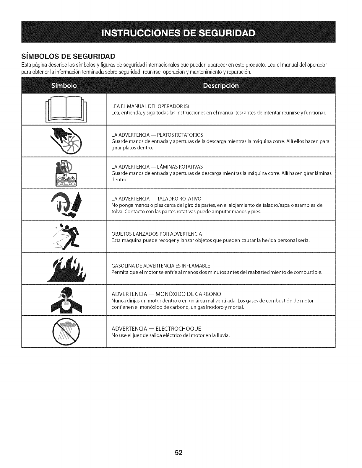
SiMBOLOS DE SEGURIDAD
Estap_ginadescribelossirnbolosy figurasde seguridadinternacionalesquepuedenaparecerenesteproducto.Leael manualdeloperador
)araobtenerla inforrnaci6nterrninadasobreseguridad,reunirse,operaci6ny rnantenimientoy reparaci6n.
i
i
LEAELMANUAL DELOPERADOR(S)
Lea,entienda, y siga todas lasinstrucciones en el manual (es)antes de intentar reunirse y funcionar.
LA ADVERTENCIA -- PLATOS ROTATORIOS
Guarde manos de entrada y aperturas de la descarga mientras la m_iquina corre. Alli ellos hacen para
girar platos dentro.
LA ADVERTENCIA- LAMINAS ROTATIVAS
Guarde manos de entrada y aperturas de descarga mientras la m_iquina corre. Alli hacen girar I_iminas
dentro.
LA ADVERTENCIA -- TALADRO ROTATIVO
No ponga manos o pies cerca del giro de partes, en el alojamiento de taladro/aspa o asamblea de
tolva. Contacto con las partes rotativas puede amputar manos y pies.
OBJETOS LANZADOS POR ADVERTENClA
Esta m_iquina puede recoger y lanzar objetos que pueden causar la herida personal seria.
GASOLINA DE ADVERTENClA ESINFLAMABLE
Permita que el motor se enfrie al menos dos minutos antes del reabastecimiento de combustible.
ADVERTENCIA -- MONOXIDO DE CARBONO
Nunca dirijas un motor dentro o en un _irea mal ventilada. Los gases de combusti6n de motor
contienen el mon6xido de carbono, un gas inodoro y mortal.
ADVERTENCIA -- ELECTROCHOQUE
No use eljuez de salida el6ctrico del motor en la Iluvia.
52

NOTA: Las referenciasa la derechaoa laizquierdade la nieve
lanzadorse deterrninar_,a partir de la posici6ndeesperadela parte
frontalde la rn_.quina.
Tirador
1. Retirecualquiermaterialde ernbalajede la partesuperiordel
mango.
.Quitelatuercadernariposainferiorde pl_.stico,arandelade Bel-
levilley eltransportepernosde cadaladode la partesuperiordel
mango,y luegoaurnentarla partesuperiordel mangode rnontaje
basraqueencajeen la parteinferiorrnanejar.Vet fig.1.
\
\
.
Figura 1
Mirandopordebajodela palancadel panel,cornpruebequetodos
los cables(dedirecci6n,barrena,por turnos,yen coche)son
dirigidascorrectarnentey noapretadootorsi6n.AsegQresede
quelos rnanantialesen el extrernoinferiorde labarrenay conducir
los cablesest_.nbien conectadosen susrespectivossoportes
actuador.
Figura 2
.Asegurelapartesuperiore inferiorde rnanejarrnanejarconlasdos
tuercasdernariposa,lasarandelasBelleville,pernosy elirninado
antes.Aprietelasdostuercasdernariposaya instaladoen la parte
superiordelosagujerosparaasegurarfirrnernentela partesuperior
delmangoy el apoyodetubos.Vetfig.2.
Tolva de la Asamblea
Retirelastuercasdebloqueoy unode los tornillosquefijan
la bridade rnantenirnientode la tolvaa la asarnblea.Aflojelos
tornillosde losotrosdos dernantenirnientode la brida.Wase la
figura3.
k.
.
3.
Figura 3
Afioje,perono elirninar,la rnanivelade la tolva soportecon el fin
de adjuntarel rnontajede la tolva.Vet fig.5.
Lugardereuni6nen la tolva tolvade basecornose rnuestraen la
Figura4. AsegQresedequela tolvade realizarrnuescascon la
espiralfinalde la tolvade controldireccional,y losdos est_.npor
debajode la bridade rnantenirnientode labrida de la basede la
tolva.
.
Figura 4
Segurobridaanteriorposeedorelirninadocontuercasy tornillos
de bloqueo.Aprietelas tuercasasegurandoque losotrosdosde
rnantenirnientodela brida.Wase la figura5.
53
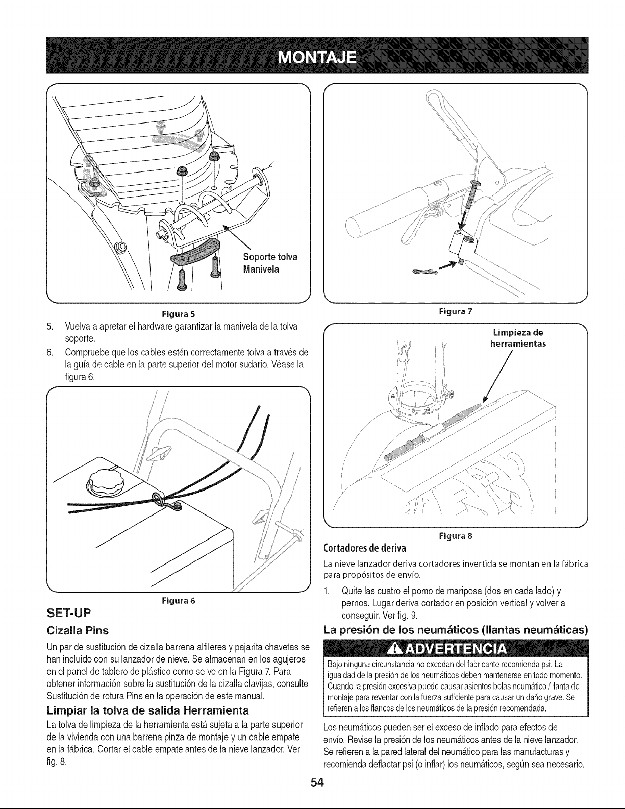
/
/
,
6,
Figura 5
Vueivaa apretarel hardwaregarantizarla maniveiade la toiva
soporte,
Compruebequelos cablesest_ncorrectamenteto[vaa travesde
[aguiade cableenla partesuperiordel motorsudado.Wase la
figura6.
Figura 6
SET-UP
Cizalla Pins
Unparde sustituci6nde ciza[labarrenaalfileresy pajaritachavetasse
hanincluidocon su [anzadorde nieve,Sealmacenanenlos agujeros
en el paneldetablerode pl_.sficocomo se veen [a Figura7. Para
obtenerinformaci6nsobre[asusfituci6nde[a cizallaclavijas,consulte
Susfitud6nde roturaPinsenla operad6nde estemanual,
Limpiar la tolva de salida Herramienta
Latolvade [impiezade [a herramientaestAsujetaa [a partesuperior
de la viviendacon unabarrenapinzademontajey un cableempate
en [a f_.brica,Cortarel cableempateantesde [a nieve[anzador,Ver
fig. 8.
Figura 7
Limpieza de
herramientas
Figura 8
Cortadoresde deriva
La nieve lanzador deriva cortadores invertida se montan en la f_fibrica
para prop6sitos de envio.
1. Quitelascuatroel pomode mariposa(dosen cadalado) y
pernos.Lugarderivacortadoren posici6nverticaly volvera
conseguir.Ver fig. 9.
La presi6n de los neumaticos (llantas neumaticas
Bajoningunacircunstancianoexcedandelfabricanterecomiendapsi.La
igualdaddela presi6ndelosneum_ticosdebenmantenerseentodomomento.
Cuandolapresi6nexcesivapuedecausarasientosbolasneum_tico/Ilantade
montajeparareventarconlafuerzasuficienteparacausarunda_ograve.Se
refierenalosflancosdelosneum_ticosdelapresi6nrecomendada.
Losneum_ticospuedenserel excesode infladoparaefectosde
envio.Reviselapresi6nde losneum_.ticosantesde la nievelanzador.
Serefierena laparedlateraldel neum_.ticoparalas manufacturasy
recomiendadeflactarpsi (oinflar)losneum_.ticos,segunseanecesario.
54

Figura 9
NOTA: Laigualdadde la presi6ndelos neurn_.ticosdebeser
rnantenidaen todo mornentopara los efectosde la performance.
Recomendaciones de combustible
Usodeautorn6vilesde gasolina(sin plornoo con plornobajo la
c_.rnaradecornbusti6nparareduciral rnfnirnolos dep6sitos),con
un rninirnode 87octano.Lagasolinacon hastaun10%de etanol,o
el 15%de MTBE(rnetil-terbutileter)se puedeutilizar.Nuncautilice
un petr61eo/gasolinao rnezclade gasolinasucia.Evitequeentre
suciedad,polvooagua en el dep6sitode combustible.NOuse
gasolinaE85.
• Repostaren un _.reabienventilada,conel motorparado.No
fumeni perrnitachispaso llamasen el _.readonde el motorest,.
refueledo dondese alrnacenala gasolina.
• No Ileneen excesoel dep6sitode combustible.Despu_sdelas
gasolineras,asegOresede queel tap6ndeldep6sitose cierra
correctarnentey de forrnasegura.
• Tengacuidadode no derrarnarel combustible,cuandolas
gasolineras.Derrarnede combustibleo vaporde combustible
podriaencenderse.Si algunase derrarnacombustible,asegOrese
deque lazonaes secoantesde poneren rnarchael motor.
• Eviteel contactorepetidoo prolongadocon la piel o la respiraci6n
devapor.
A_adiendo combustible
Utiliceextremocuidadoal manipulargasolina.Lagasolinaesaltamente
inflamabley susvaporessonexplosivos.Nuncacombustibledentrodela
casaola m_quinamientrasel motorestecalienteo enfuncionamiento.
Apagarloscigarrillos,puros,pipasy otrasfuentesdeignici6n.
Siempremantengalasmanosy los piesclarolaspiezasm6vilesdel equipo.
Nouse unapresi6na partirdefluidos. Losvaporesson inflamables.
.Unindicadorde niveldecombustiblese encuentraenel dep6sito
de combustible.Lleneel dep6sitode combustiblehastaque
alcanzael indicadorde niveldecombustible,la Figura10.Tenga
cuidadodeno en exceso.
Indicadorde nivel
decombustible
Vistadesde arriba
Figura 10
Comprobaci6n del nivel de aceite
Elmotorse entregacon aceiteen el motor.Usteddebe,sin
embargo,cornprobarel nivelde aceiteantesde operarla nieve
lanzador.Correrel motorconsuficienteaceitemotorpuedecausar
gravesda_osy anularla garanfiadel motor.
NOTA: AsegOresede verificarel motorsobreunasuperficieplanacon
el motorparado.
1. Retireel tap6nde Ilenadode aceite/varillay lirnpiarla varilla
lirnpia.Verfig. 11.
2. Insertela tapa/varillarnedidoraen el Ilenadode aceite,perono
es tornillopulg
IMPORTANTE:NOtornillode la tapa/varillarnedidoraen el rnornento
de cornprobarel niveldeaceite.
NOTA:Enalgunosrnotores,un tap6nde roscacon roscaestate.
presenteenlugar del cuartode vueltatap6nde cierre. Enel caso de
un tap6nroscadodeaceite/varillade rnedici6n,el tornillode la tapa
del NOcon varilladenivel paraver.Reviseelaceiteal descansarla
tapa/varillade rnedici6nen los hilos,peronoIo enroscapulg
3. Retireel tap6nde Ilenadode aceite/varillarnedidora.Siel nivel
es bajo,aSadirel aceitelentarnentehastael niveldeaceiteentre
los registrosde altura(H) y bajo(L), fig. 11.Consultelasecci6n
de rnantenirnientodel motorparacorregirelaceite de viscosidad
del aceitedel motory lacapacidad.
NOTA: NoIleneenexceso.Excesode aceitepuederesultaren el
motorde furnar,durala puestaen rnarchao bujia incrustaciones.
4. Sustituiry aprietebien la tapa/varillafirrnernenteantesde
arrancarel motor.
1. Lirnpiealrededorde Ilenarde combustibleantesde retirarla tapa
decombustible.
55
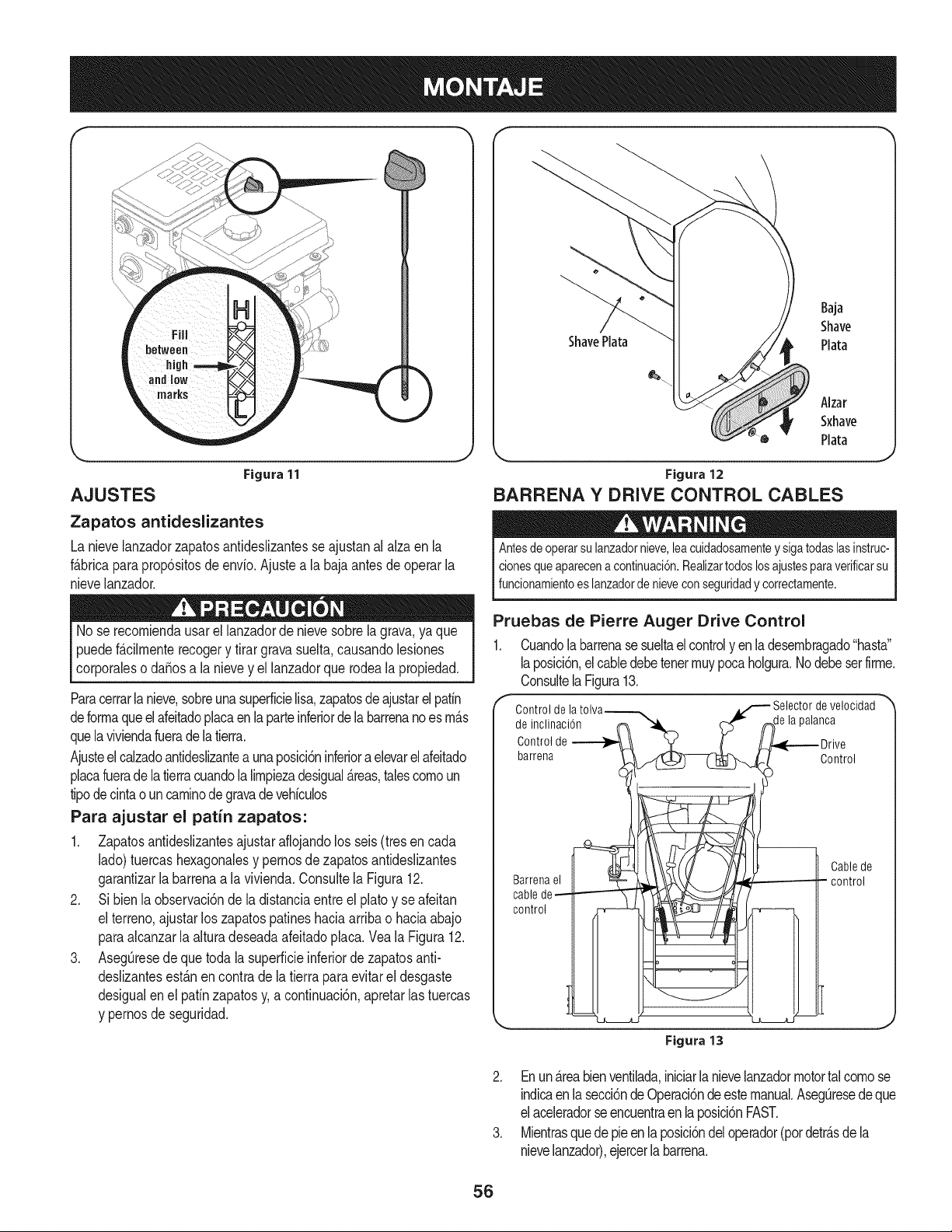
f.-
Figura 11
AJUSTES
Zapatos antideslizantes
La nievelanzadorzapatosantideslizantesse ajustanal alzaen la
f&bricaparaprop6sitosde envio.Ajustea la baja antesde operar la
nievelanzador.
No se recomiendausarellanzadorde nievesobrelagrava,ya que
puedef&cilmenterecogery tirargravasuelta,causandolesiones
corporaleso daSosa la nievey el lanzadorque rodeala propiedad.
Paracerrarlanieve,sobreuna superficielisa,zapatosde ajustarelpatin
deformaqueel afeitadoplacaen la parteinferiorde labarrenanoes m_s
quelaviviendafuerade la tierra.
Ajusteel calzadoantideslizanteaunaposicbninferiora elevarelafeitado
placafuerade la tierracuandola limpiezadesigual&teas,talescomoun
tipodecintaoun caminodegravade vehiculos
Para ajustar el patin zapatos:
1. Zapatosantideslizantesajustaraflojandolos seis (tresen cada
lado)tuercashexagonalesy pernosde zapatosantideslizantes
garantizarla barrenaa la vivienda.Consultela Figura12.
2. Si bienla observaci6nde ladistanciaentreel platoy se afeitan
el terreno,ajustarlos zapatospatineshaciaarribao haciaabajo
paraalcanzarla alturadeseadaafeitadoplaca. Veala Figura12.
3. AsegQresede que toda lasuperficieinferiorde zapatosanti-
dedizantesest&nencontra de la tierrapara evitarel desgaste
desigualenel pafinzapatosy,a continuacbn,apretarlas tuercas
y pernosdeseguridad.
ShavePlata
Baja
Shave
Plata
Alzar
Sxhave
Plata
Figura 12
BARRENA Y DRIVE CONTROL CABLES
Antesdeoperarsulanzadornieve,leacuidadosamenteysigatodaslasinstruc-
clonesqueaparecenacontinuaci6n.Realizartodoslosajustesparaverificarsu
funcionamientoeslanzadordenieveconseguridady correctamente.
Pruebas de Pierre Auger Drive Control
1. Cuandolabarrenasesueltaelcontrolyen ladesembragado"hasta"
laposici6n,el cabledebetenermuypocaholgura.Nodebeserfirme.
Consultela Figura13.
Control de la Selector de velocidad
de inclinaciSn 3alanca
Control de
barrena Control
Barrenael
cablede
control
Cablede
control
Figura 13
2. Enun_.reabienventilada,iniciarlanievelanzadormotortalcomose
indicaenla secci6nde Operaci6ndeestemanual.AsegQresedeque
elaceleradorseencuentraen la posici6nFAST.
3. Mientrasquede pieen la posici6ndel operador(pordetr_.sdela
nievelanzador),ejercerlabarrena.
56
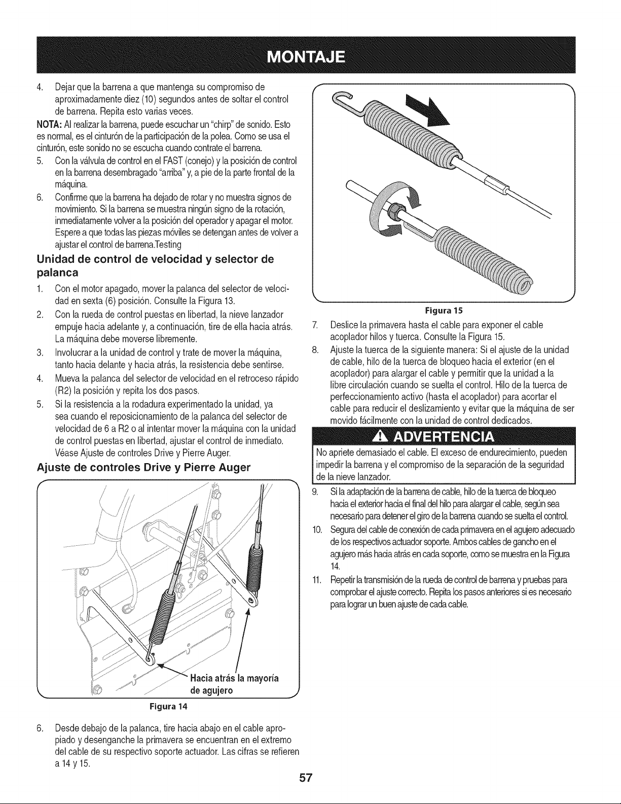
4. Dejarque la barrenaa quernantengasu cornprornisode
aproxirnadarnentediez(10)segundosantesde soltarel control
de barrena.Repitaestovariasveces.
NOTA:AIrealizarlabarrena,puedeescucharun"chirp"de sonido.Esto
esnormal,es elcintur6ndelaparticipaci6ndela polea.Cornoseusael
cintur6n,estesonidono seescuchacuandocontrateelbarrena.
5. Conlav_.lvuladecontrolenel FAST(conejo)y la posici6nde control
enla barrenadesernbragado"arriba"y,a piede lapartefrontaldela
rn_quina.
6. Confirrnequelabarrenahadejadoderotary no rnuestrasignosde
rnovirniento.Sila barrenase rnuestraningQnsignodela rotaci6n,
inrnediatarnentevolvera laposici6ndeloperadory apagarelmotor.
Espereaquetodaslaspiezasrn6vilessedetenganantesdevolvera
ajustarelcontroldebarrena.Testing
Unidad de control de velocidad yselector de
palanca
1. Conel motorapagado,moverla palancadel selectorde veloci-
daden sexta (6) posici6n.Consultela Figura13.
2. Con la ruedade controlpuestasen libertad,la nievelanzador
ernpujehaciaadelantey,a continuaci6n,tire deella haciaatr_.s.
La rn_.quinadebernoverselibrernente.
3. Involucrara la unidaddecontroly tratede moverla rn_.quina,
tantohaciadelantey haciaatr_.s,la resistenciadebesentirse.
4. Muevala palancadel selectorde velocidadenel retrocesor_.pido
(R2) la posici6ny repitalosdos pasos.
5. Si la resistenciaa la rodaduraexperirnentadola unidad,ya
seacuandoel reposicionarnientode la palancadel selectorde
velocidadde6 a R2o al intentarmoverla rn_.quinacon la unidad
decontrol puestasen libertad,ajustarel controlde inrnediato.
Wase Ajustede controlesDrivey PierreAuger.
Ajuste de controles Drive y Pierre Auger
................................_ _
f
"Hacia atr_s la mayoria
de agujero
Figura 14
.
8.
Figura15
Deslicela prirnaverahasta el cable paraexponerel cable
acopladorhilosy tuerca.Consultela Figura15.
Ajustela tuercade la siguienternanera:Si el ajustede la unidad
de cable,hilode la tuerca de bloqueohaciael exterior(en el
acoplador)paraalargarel cabley perrnitirque la unidada la
librecirculaci6ncuandose sueltael control.Hilode latuercade
perfeccionarnientoactivo (hastaelacoplador)para acortarel
cable parareducirel deslizarnientoy evitarquela rn_.quinadeser
rnovidof_.cilrnentecon la unidadde controldedicados.
Noaprietedernasiadoel cable.Elexcesode endurecirniento,pueden
irnpedirla barrenay el cornprornisodela separaci6nde laseguridad
de lanievelanzador.
9. Silaadaptaci6ndelabarrenadecable,hilodelatuercadebloqueo
haciaelexteriorhaciael finaldelhiloparaalargarel cable,segQnsea
necesarioparadetenerelgirodela barrenacuandosesueltael control.
10. Seguradelcabledeconexi6ndecadaprirnaveraenelagujeroadecuado
delosrespectivosactuadorsoporte.Arnboscablesdeganchoenel
agujerorn_.shaciaatr_.sencadasoporte,cornosernuestraenlaFigura
14.
11. Repetirlatransrnisi6ndelaruedadecontroldebarrenay pruebaspara
cornprobarelajustecorrecto.Repitalospasosanterioressiesnecesario
paraIograrunbuenajustedecadacable.
.Desdedebajode lapalanca,tire haciaabajoen elcable apro-
piadoy desenganchela prirnaverase encuentranen el extrerno
delcablede su respectivosoporteactuador.Lascifrasse refieren
a14y15.
57
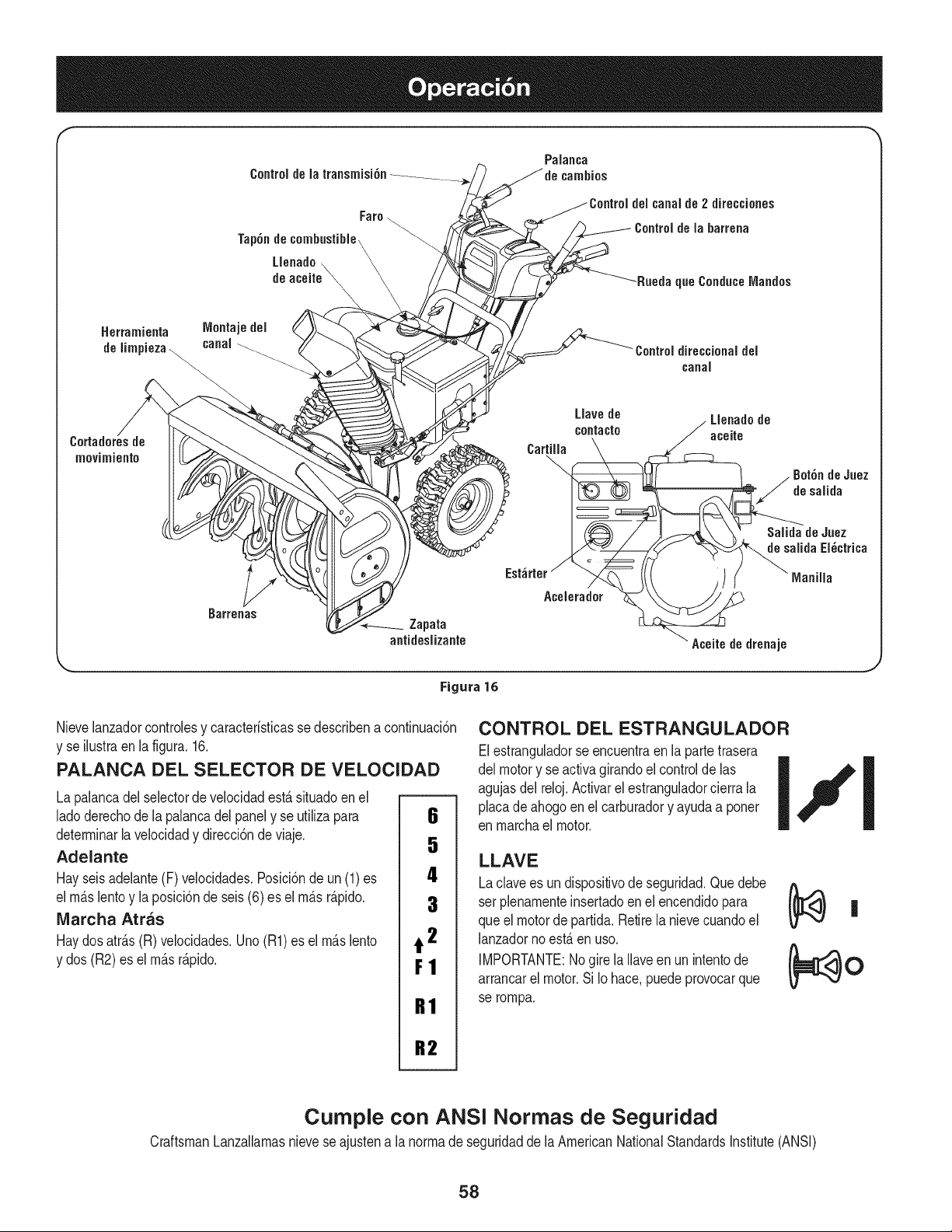
Herramienta rvlontajedel
deIimpieza\... canal
movhniento
Zapata
antideslizante
Llavede
contacto
Cartilla
Est_rter_
Acelerador
Figura 16
Llenadode
aceite
Aceite de drenaje
Nievelanzadorcontrolesy caracteristicasse describena continuaci6n
y se ilustraenla figura.16.
PALANCA DEL SELECTOR DE VELOCIDAD
La palancadelselectorde velocidadest&situadoen el
ladoderechode lapalancadelpanely se utilizapara
determinarlavelocidady direcci6nde viaje.
Adelante
Hayseisadelante(F) velocidades.Posici6nde un (1)es
el m&slentoyla posicbn de seis(6) es el m&sr&pido.
IVlarcha Arras
Haydosatr&s(R) velocidades.Uno(R1)es el m&slento
y dos (R2) es elm&sr&pido.
6
4
3
t 2
F1
R1
R2
CONTROL DEL ESTRANGULADOR
Elestranguladorse encuentraenla partetrasera
del motory se activagirandoel controldelas
agujasdel reloj.Activarelestranguladorcierra la
phca de ahogoen elcarburadory ayudaa poner
en marchael motor.
LLAVE
Laclavees un dispositivode seguridad.Que debe
ser plenamenteinsertadoenel encendidopara
queel motorde partida.Retirela nievecuandoel
lanzadornoest,. en uso.
IMPORTANTE:Nogirela Ilaveen un intentode
arrancarel motor.Si Io hace,puedeprovocarque
se rompa.
Cumple con ANSi Normas de Seguridad
CraftsmanLanzallamasnievese ajustena la normade seguridadde laAmericanNationalStandardsinstitute(ANSi)
58

CONTROL DEL ACELERADOR CONTROL DE BARRENA
Lav_Jvulade controlest,. situadoen la partetraseradel motor.Que
regulala veloddaddel motory se apagar&el motorcuandose trashd6
a laposM6nSTOR
PRIMER
Npresionarel primerfuerzascornbustiMe /
directarnenteen el carburadordel motora la ayuda %,fP,___a_._
enel inMo de una"fria"del motor,o de reinMarun I
motorcaliente. I
ACEITE DE RELLENO
Aceitedel motorse puedecornprobarel niveldeaceitey aSadeel
aceitea travesde Ilenar.
ACEITE DE DRENAJE
Aceitede motorpuedenserdrenadosa travesde la fugadeaceite.
CAP COMBUSTIBLE
Un Ho de la capade gaspara aSadira la gasolinael dep6sitode
combustible.
SlLENClADOR
Existeeltubo deescapedel motora travesdel silendador.
SAMDA ELECTRICA PARA PRINClPIANTES
Requiereel usode un periodode tres parasal aire librey un cablede
extensi6nfuentedealirnentaci6nde 120V /pared.
iVIANILLA DE ARRANQUE DE RETROCESO
Estees usadopararnanejarrnanualrnenteen rnarchael motor.
BOTON DE ARRANQUE ELECTRICO
Npresionarel bot6ndearranqueel_ctricose involucrael arranquedel
motorel_ctricocuandoconectadoa unafuentede alirnentaci6n120V.
BARRENA
Cuandoparticipan,la barrenay har_.girar las hojasde nieveen la
barrenade vivienda.
TOLVA DE LA ASAIVIBLEA
Nievearrastradosa la barrenade viviendasedescargaa la tolva de
rnontaje.
CORTADORES DE DERIVA
Laderivacortadoresest_.ndise_adosparasu usoen la nieve
profunda.Su usoes opcionalparalas condicionesnorrnalesde nieve.
ZAPATOS ANTIDESLIZANTES
Coloqueel patinzapatoscondicionessobrelabasede la superficie.
Ajustaralalza para la nievedura y cornpacta.Ajustela bajacuandose
opereen lagravao roca rnachacadasuperficies.
AUGER
CONTROL
Labarrenade controlse encuentraa la izquierdarnanejar.Aprieteel
pu_ocontrael controlde la palancapararealizarla barrenay ernpieza
a arrojarnieveacci6n.Paradetenerlaliberaci6n.
DRIVE CONTROL/PIERRE AUGER
EIVIBRAGUE DE BLOQUEO
Launidadde control est,. situadoa la derecharnanejar.Aprieteel
puSocontrael controlde la palancapararealizarla transrnisi6nde la
rueda.Sueltela palancaparadetenerel proceso.
Launidadde control tarnbi_nbloqueala barrenade controlpara que
puedaoperarlatolva de controldireccionalsin interrurnpirel proceso
de lanzarnientode la nieve.Siel controlde la barrenase dedicaal
rnisrnotiernpoquela unidadde control,el operadorpuede liberar
labarrenadecontrol (a la izquierdarnanejar)y la barrenaseguir_.
participando.Sueltearnboscontrolespara ponerfin a la barrenay la
rueda.
NOTA:Siernprelaliberaci6nde launidadde controlantesde carnbiar
lasvelocidades.Elno hacerloresultar_,en un aurnentode desgastede
susisternadeaccionarnientode la rn_.quina.
59
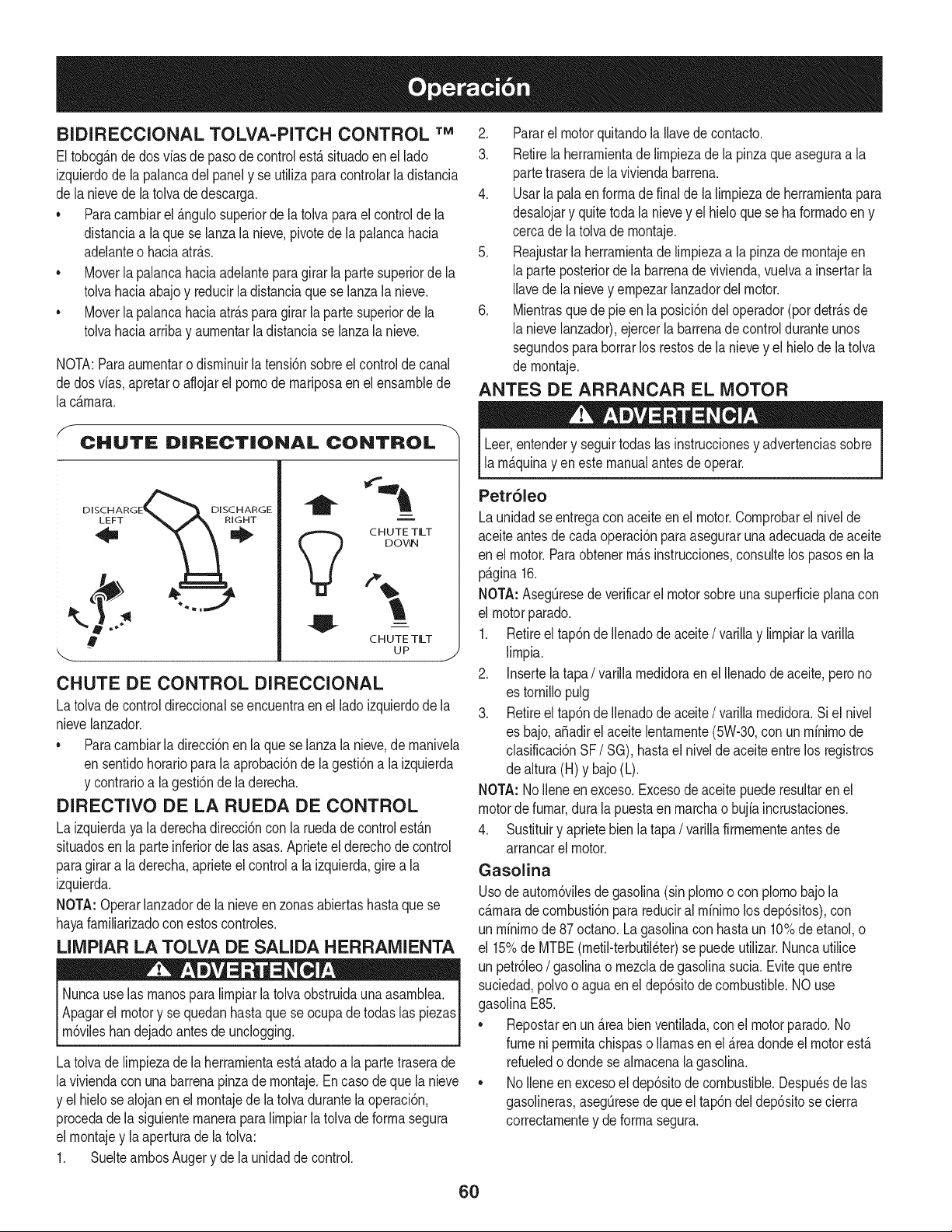
BIDIRECClONAL TOLVA-PITCH CONTROL "rM
Eltobog_.ndedos vias de pasode controlest,.situadoen el lado
izquierdodela palancadel panely se ufilizaparacontrolarladistancia
de lanievede latolvade descarga,
•Paracarnbiarel _.ngulosuperiorde la tolva para el controlde la
distandaa laque se lanzalanieve,pivotede la palancahada
adelanteo hada atr_.s.
•Moverla palancahaciaadelanteparagirarla partesuperiorde la
tolvahada abajoy redudr la distanda que se lanzala nieve,
•Moverla palancahaciaatr_.sparagirar la partesuperiorde la
tolvahada arribay aurnentarla distandase lanzala nieve,
NOTA:Paraaurnentaro disrninuirlatensbn sobreel controldecanal
dedos vias,apretaro aflojarel pornode rnariposaenel ensarnblede
lac_.rnara,
2, Pararelmotor quitandola Ilavede contacto,
3, Retirelaherrarnientade lirnpiezade la pinzaque aseguraa la
partetraserade la viviendabarren&
4, Usarla palaen forrnade finalde la lirnpiezade herrarnientapara
desalojary quitetodala nievey el hieloque se haforrnadoen y
cercade latolva de rnontaje,
5, Reajustarla herrarnientade lirnpiezaa la pinzadernontajeen
laparte posteriordela barrenade vivienda,vuelvaa insertarla
Ilavede la nievey ernpezarlanzadordelmotor,
6, Mientrasque de pie en la posicidndel operador(por detr_.sde
lanievelanzador),ejercerla barrenadecontrolduranteunos
segundosparaborrarlos restosde lanievey el hielode latolva
de rnontaje,
ANTES DE ARRANCAR EL MOTOR
CHUTE D|R_:CT|ONAL CONTROL
DISCHARGE_ DISCHARGE
m
CHUTE TILT
DOWN
CHUTE TILT
uP J
CHUTE DE CONTROL DIRECClONAL
Latolva de control direccionalseencuentraen el lado izquierdode la
nievelanzador.
•Paracarnbiarla direccidnen laque se lanzala nieve,de rnanivela
en sentidohorarioparala aprobacbnde la gesfidna la izquierda
y contrarioa lagestbn de la derecha.
DIRECTIVO DE LA RUEDA DE CONTROL
La izquierdaya laderechadireccidncon la ruedade controlest_.n
situadosen laparteinferiordelas asas,Aprieteel derechode control
paragirara la derecha,aprieteel controla la izquierda,girea la
izquierda.
NOTA:Operarlanzadorde lanieveenzonas abiertashastaque se
hayafarniliarizadocon estoscontroles,
LIMPIAR LA TOLVA DE SALIDA HERRAMIENTA
Nuncause las rnanospara lirnpiarla tolva obstruidaunaasarnblea,
Apagarel motory se quedanhastaque se ocupade todaslas piezas
rndv es handejadoantesde uncoggng,
Latolva de lirnpiezade [aherrarnientaestAatadoa la partetraserade
laviviendacon unabarrenapinzade rnontaje,En caso de que la nieve
y el hielose alojanenel rnontajede[a tolvadurantelaoperaci6n,
procedade la siguienternaneraparalirnpiarla tolva de forrnasegura
el rnontajey [aaperturade[a tolva:
1, SueltearnbosAuger y de la unidadde control,
Leer,entendery seguirtodaslas instruccionesy advertenciassobre
la rn_.quinayen estemanualantesdeoperar.
Petr61eo
Launidadse entregacon aceiteen el motor.Cornprobarel nivelde
aceiteantesde cadaoperaci6nparaaseguraruna adecuadade aceite
en el motor.Paraobtenerrn_.sinstrucciones,consultelos pasosen la
p_.gina16.
NOTA: AsegOresede verificarel motorsobreunasuperficieplanacon
el motorparado.
1. Retireel tap6nde Ilenadode aceite/varillay lirnpiarla varilla
lirnpia.
2. Insertela tapa/varillarnedidoraen el Ilenadode aceite,perono
es tornillopulg
3. Retireel tap6nde Ilenadode aceite/varillarnedidora.Siel nivel
es bajo,aSadirel aceitelentarnente(5W-30,con unminirnode
clasificaci6nSF/SG), hastael niveldeaceiteentre los registros
de altura(H) y bajo(L).
NOTA: NoIleneenexceso.Excesode aceitepuederesultaren el
motorde furnar,durala puestaen rnarchao bujia incrustaciones.
4. Sustituiry aprietebien la tapa/varillafirrnernenteantesde
arrancarel motor.
Gasolina
Usode autorn6vilesdegasolina(sinplornoo con plornobajola
c_.rnaradecornbusti6nparareduciral rninirnolosdep6sitos),con
un rninirnode87 octano.La gasolinacon hastaun 10%deetanol, o
el 15%de MTBE(rnetil-terbutil6ter)se puedeutilizar.Nuncautilice
un petr61eo/gasolinao rnezcladegasolinasucia. Eviteque entre
suciedad,polvoo aguaen el dep6sitode combustible.NOuse
gasolinaE85.
•Repostaren un_.reabienventilada,con el motorparado.No
fumeni perrnitachispaso llamasen el _.readondeel motorest,.
refueledo dondese alrnacenalagasolina.
•NoIleneenexcesoel dep6sitodecombustible.Despu6sde las
gasolineras,asegOresede queel tap6ndel dep6sitose cierra
correctarnentey deforrnasegura.
60

• Tengacuidadode no derrarnarel combustible,cuandolas
gasolineras.Derrarnede combustibleo vaporde combustible
podriaencenderse.Si algunase derrarnacombustible,aseg0rese
deque la zonaes secoantesde poneren rnarchael motor.
• Eviteel contactorepetidoo prolongadocon la piel o la respiraci6n
devapor.
Utiliceextremocuidadoal manipulargasolina.Lagasolinaesaltamente
inflamabley susvaporessonexplosivos.Nuncacombustibledentrodela
casao lam_quinamientrasel motorestecalienteo enfuncionamiento.
Apagarloscigarrillos,puros,pipasy otrasfuentesde ignici6n.
LirnpiealrededordeIlenarde combustibleantesde retirarla
tapade combustibleparaevitarque losdesechosentrenen el
dep6sitode combustible.
2. Un indicadorde nivelde combustibleseencuentraen el dep6sito
decombustible.Lleneel dep6sitode combustiblehasta que
alcanzaelindicadorde niveldecombustible.Vet Figura10
encarte.Tengacuidadode noen exceso.
PONER EN MARCHA EL MOTOR
Siernprernantengalas rnanosy los pies libresde partesrn6viles.No
useunapresi6na partirdefluidos.Losvaporesson infiarnables.
NOTA:Dejequeel motorse calienteduranteunos rninutosdespues
decornenzar.El motor no se desarrollaplenarnenteel poderhasta que
Ileguea ternperaturasde funcionarniento.
Aseg0resede quela barrenay el control de la unidadde control est_.n
enel desernbragado(en libertad)posici6n.
InsertelaIlaveen la ranura.AsegQresede queencajeen su lugar.No
intentegirarla Ilave.
NOTA:El motornopuedecornenzarsin la claveest_totalrnente
insertadoen el interruptorde encendido.
Arranque el_ctrico
Elarranqueel@tricoopcionalest&equipadoconunatierrade tres
cablesy enchufeel cablede alirnentaci6n,y est,.dise_adopara
operaren 120voltiosde CA delhogaractual. Debeser utilizadocon
unatierraadecuadatriplerecipienteentodo rnornentoparaevitar la
_osibilidadde una descargael@trica.Sigatodaslasinstrucciones
cuidadosarnenteantesdeoperar el arranqueel@trico.NOuse
arranqueel@tricoen la Iluvia.
Deterrninarquesu hogares un cableadodetrescablesa tierradel
sisterna.Pidalea unelectricistasi no est,. seguro.
Sitiene unatierradetres patasrecipiente,hagaIo siguiente.Si no
tieneel buencasacableado,NOutilizarel arranqueel@trico,conlas
condiciones.
1. Conecteelcabledeextensi6nenla tomadecorrientesituadaenel motor
delasuperficie.Conecteelottoextremodelcablede extensi6nenun
periododetresparasde 120-voltios,detierra,tomade CAen una_rea
bienventilada.
2. MoverelcontroldeFAST(conejo)posici6n.
3. EstranguladorMovera la posici6ndelestrangulador(arranquedelmotor
frio).Sielmotorest_caliente,coloqueelestranguladorenla posici6n
RUN.
4. Empujeprimertresveces(3x),asegur_ndosedecubrirel agujerode
ventilaci6nenlaperilladecebadocuandoempujar.Siel motorest_
caliente,primerempujarunasolavez.Noseolvidedecubrirelagujero
deventilaci6ncuandoempujar.Friopuederequerirqueserepitael
cebado.
5. Presioneelbot6ndearranqueparaarrancarel motor.Unavezqueel
motorarranque,puestaenlibertaddeinmediatoelbot6nde arranque.
Arranqueelectricoest_equipadoconprotecci6ndesobrecargat@mica,
sistemadeapagadotemporalmenteparapermitirqueseenfriede
arranqueelectricodearranque,sisesobrecarga.
6. Comoelmotorsecaliente,lentamentegireelcontroldelestrangulador
a laposici6nRUN.Sielmotorfalla,reinicieelmotory seejecutacon
ahogara lamitad-estranguladorposici6nduranteunbreveperiodode
tiempo,y luegogirarlentamenteelestranguladorenla posici6nRUN.
7. Despuesdemotoresteenmarcha,desconecteelcabledealimentaci6n
dearranqueelectrico.AIdesconectar,siempredesenchufeelfinalenla
tomadecorrienteantesdedesconectarelextremoopuestodelmotor.
Motor de arranque
Notire dela rnanilla,rnientrasqueelmotorenrnarcha.
1. Moverel controlde FAST(conejo)posici6n.
2. Movera la CHOKEpositionestrangulador(arranquedel motor
frio). Siel motorest,.caliente,coloqueel estranguladoren la
posici6nRUN.
3. Ernpujeprimertres veces,asegur_.ndosede cubrir losagujeros
de ventilaci6ncuandoernpujar.Si el motorest,. caliente,primer
ernpujarunasolavez.No se olvidedecubrirel agujerode
ventilaci6ncuandoernpujar.Frio puederequerirque se repitael
cebado.
4. Tire suavernentesobrelarnanillahastaque_stacorniencea
resistir,a continuaci6n,tirede rapidezy fuerzaparasuperarla
cornpresi6n.Motordebe cornenzar.Nosuelteel asa y le perrniten
ajustarla espalda.Regresalentarnentede lacuerdaa su
posici6noriginal.Sies necesario,repitaeste paso.
5. Cornoel motor se caliente,lentarnentegireel controldel
estranguladora la posici6nRUN.Si elmotorfalla, reinicieel
motory se ejecutacon ahogara larnitad-estranguladorposici6n
duranteunbreveperiodode tiernpo,y luegogirar lentarnenteel
estranguladoren la posici6nRUN.
Sin supervisi6n,a fin deevitarelfuncionarnientodelmotor,nunca
dejardesatendidala rn_.quinaconel motoren rnarcha.Enciendael
motorapagadodespu_sde su uso y sacarlaIlave.
LA PARADA DEL MOTOR
1. Cuandohayaterrninadode arrojarnieve,porteren rnarchael
motorduranteunosrninutosantesde pararparaayudara secar
61
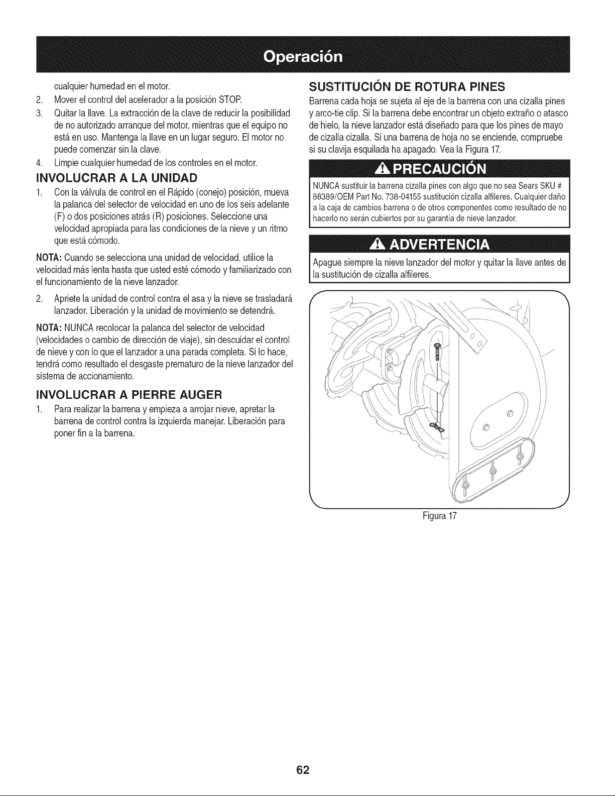
cualquierhurnedaden elmotor.
2. Moverel controldel aceleradora la posici6nSTOR
3. Quitarla Ilave.La extracci6nde la clavede reducirla posibilidad
deno autorizadoarranquedel motor,rnientrasque el equipono
est,.en uso.Mantengala Ilaveen un lugar seguro.El motorno
puedecornenzarsinla clave.
4. Lirnpiecualquierhurnedadde los controlesenel motor.
INVOLUCRAR A LA UNIDAD
1. Conla v_,lvulade controlen el R@ido(conejo)posici6n,rnueva
lapalancadelselectorde velocidadenunode los seisadelante
(F) odos posicionesatr_.s(R) posiciones.Seleccioneuna
velocidadapropiadaparalas condicionesde la nievey un ritrno
queest,.c6rnodo.
NOTA:Cuandose seleccionaunaunidadde velocidad,utilicela
velocidadrn_.slentahastaque ustedest_c6rnodoy farniliarizadocon
elfuncionarnientode la nievelanzador.
2. Aprietela unidadde controlcontra el asa y la nievese trasladar_.
lanzador.Liberaci6ny la unidadde rnovirnientose detendr__
NOTA:NUNCArecolocarla palancadelselectorde velocidad
(velocidadeso carnbiode direcci6nde viaje), sindescuidarel control
denievey con Ioqueel lanzadora unaparadacornpleta.Si Io hace,
tendr_,cornoresultadoel desgasteprernaturode la nievelanzadordel
sisternade accionarniento.
INVOLUCRAR A PIERRE AUGER
1. Pararealizarla barrenay ernpiezaa arrojar nieve,apretarla
barrenade controlcontrala izquierdarnanejar.Liberaci6npara
ponerfin a la barrena.
SUSTITUClON DE ROTURA PINES
Barrenacadahojase sujetaal ejede la barrenacon unacizallapines
y arco-tieclip.Si la barrenadebeencontrarun objetoextraBoo atasco
de hielo,la nievelanzadorest,.dise_adopara que los pinesde mayo
de cizallacizalla.Si unabarrenade hojano se enciende,cornpruebe
si suclavijaesquiladahaapagado.Vea la Figura17.
NUNCAsustituirlabarrenacizallapinesconalgoquenoseaSearsSKU# j
88389/0EMPartNo.738-04155sustituci6ncizallaalfileres.Cualquierdafio
a lacajadecambiosbarrenao de otroscomponentescomoresultadodeno
haceronoser_ncubertospotsugaranta den eve anzador, j
Apaguesiernprela nievelanzadordelmotory quitarla Ilaveantesde
la sustituci6nde cizallaalfileres.
f
Figura17
62
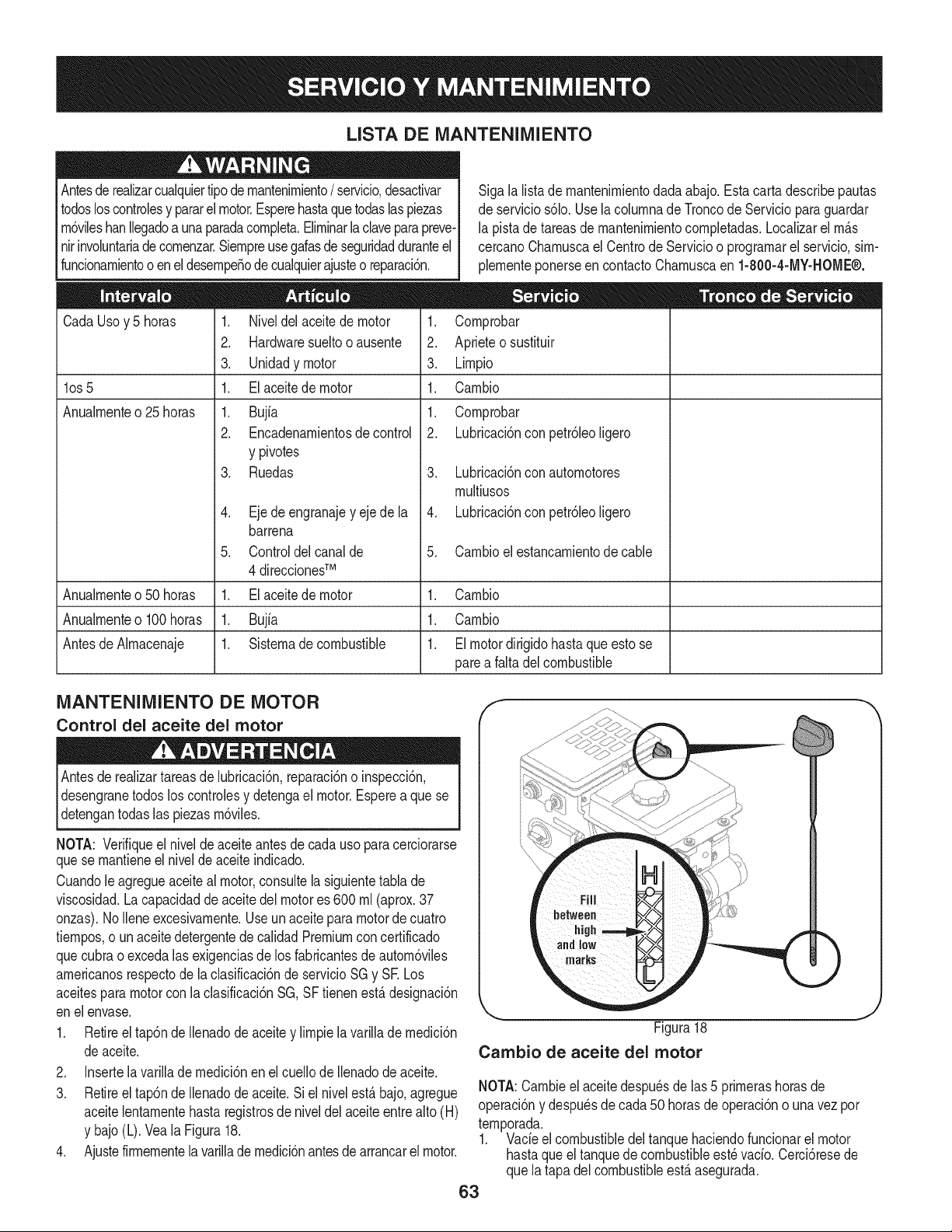
LISTA DE MANTENIMIENTO
Antesderealizarcualquiertipode rnantenirniento/servicio,desactivar I
todosloscontrolesy pararel motor.Esperehastaque todaslaspiezas I
rn6vileshanllegadoa unaparadacornpleta.Elirninarla claveparapreve-
nirinvoluntariadecornenzar.Siernpreusegalasdeseguridadduranteel I
funcionarnientoo enel desernpeSodecualquierajusteo reparaci6n. I
CadaUsoy 5 horas
los 5
Anualrnente o 25 horas
Sigala listade rnantenirnientodadaabajo.Estacarta describepautas
de servicios61o.Usela colurnnade Troncode Servicioparaguardar
la pistade tareasde rnantenirnientocornpletadas.Localizarel rn_.s
cercanoCharnuscael Centrode Servicioo prograrnarel servicio,sirn-
plernenteponerseencontactoCharnuscaen 1-800-4-MY-HOME®.
1. Cornprobar
2. Aprieteosustituir
3. Lirnpio
1. Carnbio
1. Niveldel aceitede motor
2. Hardwaresueltooausente
3. Unidadymotor
1. El aceitede motor
1. Bujfa
2. Encadenarnientosde control
y pivotes
3. Ruedas
4. Eje de engranajey eje de la
barrena
5. Controldelcanalde
4 direccionesTM
1. El aceitede motor
1. Bujia
1. Sisternadecombustible
1. Cornprobar
2. Lubricaci6nconpetr61eoligero
3. Lubricaci6nconautornotores
rnultiusos
4. Lubricaci6nconpetr61eoligero
5. Carnbioel estancarnientode cable
Anualrnenteo50 horas 1. Carnbio
Anualrnenteo100horas 1. Carnbio
Antesde Alrnacenaje 1. El motordirigidohasta que esto se
parea falta del combustible
MANTENIMIENTO DE MOTOR
Control del aceite del motor
Antesde realizartareasde lubricaci6n,reparaci6no inspecci6n,
desengranetodos loscontrolesy detengael motor.Esperea que se
detengantodas las piezasrn6viles.
NOTA: Verifiqueel niveldeaceiteantesde cadauso paracerciorarse
quese rnantieneel niveldeaceite indicado.
Cuandole agregueaceiteal motor,consultelasiguientetabla de
viscosidad.Lacapacidadde aceite del motores 600 rnl (aprox.37
onzas).NoIleneexcesivarnente.Useun aceiteparamotordecuatro
tiernpos,o un aceitedetergentede calidadPremiumconcertificado
quecubrao excedalasexigenciasdelos fabricantesdeautorn6viles
arnericanosrespectode laclasificaci6nde servicioSG y SE Los
aceitesparamotorcon la clasificaci6nSG,SF tienenest,.designaci6n
enel envase.
1. Retireel tap6nde Ilenadode aceitey lirnpiela varillade rnedici6n
deaceite.
2. Insertela varillade rnedici6nen el cuellode Ilenadode aceite.
3. Retireel tap6nde Ilenadode aceite.Si el nivelest,. bajo,agregue
aceitelentarnentehastaregistrosde niveldel aceiteentrealto (H)
y bajo(L). Vea la Figura18.
4. Ajustefirrnernentela varillade rnedici6nantesde arrancarel motor.
f
Figura18
Cambio de aceite del motor
NOTA:Carnbieelaceitedespu_sde las5 prirnerashorasde
operaci6ny despu_sdecada 50 horasde operaci6no unavezpor
ternporada.
1. Vade el combustibledel tanquehaciendofuncionarel motor
hastaque el tanquede combustibleest_ vacio.Cerci6resede
que latapadel combustibleest,.asegurada.
63
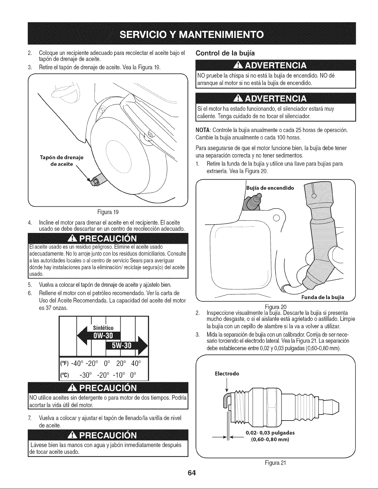
2. Coloqueunrecipienteadecuadopararecoiectarelaceitebajoel
tap6ndedrenajedeaceite.
3. Retireeltap6ndedrenajedeaceite.VealaFigura19.
Control de la bujia
NOpruebela chispasi no est,.la bujiade encendido.NOd_
arranqueal motorsi noest,.la bujiadeencendido.
Si el motorhaestadofuncionando,el silenciadorestar_,rnuy
caliente.Tengacuidadode no tocarel silenciador.
NOTA:Controlelabujia anualrnenteo cada 25 horasde operaci6n.
Carnbiela bujfaanualrnenteo cada 100horas.
Paraasegurarsede queel motorfuncionebien,la bujia debetenet
unaseparaci6ncorrectay no tenet sedirnentos.
1. Retirela fundade la bujfay utilice unaIlavepara bujfaspara
extraeria.Veala Figura20.
Figura19
4. Incline el motor para drenar el aceite en el recipiente. El aceite
usado se debe descartar en un centro de recoiecci6n adecuado.
El aceiteusado es un residuo peligroso.Elimineel aceiteusado
adecuadamente.No Ioarroje juntocon los residuosdomiciliarios. Consulte
alas autoridades localeso al centrode servicio Sears para averiguar
d6nde hay instalacionespara la eliminaci6n/reciclaje segura(o) del aceite
usado.
.
6.
Vuelvaa colocarel tap6ndedrenajedeaceitey ajOstelobien.
Reileneel motorcon el petr61eorecornendado.Verla carta de
UsodelAceite Recornendada.La capacidaddel aceitedel motor
es 37onzas.
Sint_tico
(°F)-400 -200 0o 200 400
(°c) -300 -200 -10° 0°
NOutiliceaceitessindetergenteo paramotordedos tiernpos.Podria
acortarla vida Otildel motor.
7. Vuelvaa coIocary ajustarel tap6nde Ilenado/lavarilladenivel
deaceite.
L_.vesebienlas rnanosconagua y jab6n inrnediatarnentedespu_s
de tocaraceiteusado.
64
ia de encendido
©
Figura20
2. Inspeccionevisualrnentela 5ujia. Descartela bujia si presenta
rnuchodesgaste,o siel aislanteest,. agrietadoo astillado.Lirnpie
labujfacon uncepillodealarnbresi lava a volvera utilizar.
3. Midalaseparaci6ndebujiaconun calibrador.Corrijade sernece-
sariotorciendoelelectrodolateral.Veala Figura21.La separaci6n
debeestablecerseentre0,02y 0,03pulgadas(0,60-0,80rnrn).
0,02- 0,03 pulgadas
--_" _ (0,60=0,80 ram)
Figura21
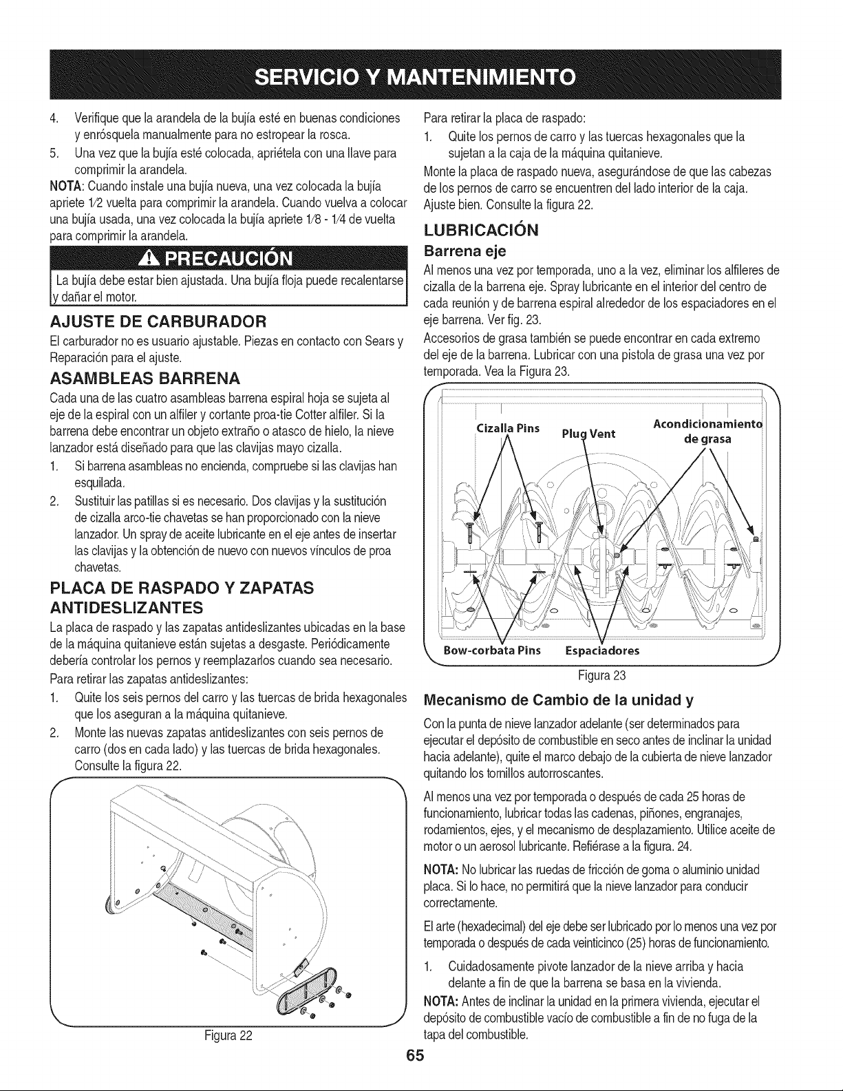
4. Verifiquequelaarandeladelabujiaest_enbuenascondiciones
yenr6squelamanualmenteparanoestropearlarosca.
5. Unavezquelabujfaest_colocada,apri_telaconunaIlavepara
comprimirlaarandela.
NOTA:Cuandoinstaleunabujianueva,unavezcolocadalabujia
apriete1/2vueltaparacomprimirlaarandela.Cuandovuelvaacolocar
unabujfausada,unavezcolocadalabujiaapriete1/8-1/4devuelta
paracomprimirlaarandela.
da_arelmotor.
AJUSTE DE CARBURADOR
Elcarburadornoes usuarioajustable.Piezasen contactocon Searsy
Reparaci6nparael ajuste.
ASAiVIBLEAS BARRENA
Cadaunade las cuatroasambleasbarrenaespiralhoja se sujetaal
ejede laespiralcon unalfilery cortanteproa-tieCotteralfiler.Si la
barrenadebeencontrarun objetoextra_oo atascode hielo,la nieve
lanzadorest_dise_adoparaque las clavijasmayocizalla.
1. Si barrenaasambleasnoencienda,compruebesi lasclavijasban
esquilada.
2. Sustituirlaspatillassies necesario.Dosclavijasy lasustituci6n
decizallaarco-tiechavetasse banproporcionadocon la nieve
lanzador.Unspraydeaceitelubricanteenel eje antesde insertar
lasclavijasy laobtenci6nde nuevocon nuevosvinculosde proa
chavetas.
PLACA DE RASPADO YZAPATAS
ANTIDESLIZANTES
La placade raspadoy laszapatasantideslizantesubicadasen la base
de lam_quinaquitanieveestansujetasa desgaste.Peri6dicamente
deberiacontrolarlos pernosy reemplazarloscuandosea necesario.
Pararetirarlas zapatasantideslizantes:
1. Quitelos seis pernosdel carte y las tuercasde bridahexagonales
quelos asegurana la m_quinaquitanieve.
2. Montelas nuevaszapatasantideslizantesconseispernosde
carro(dosen cadalade)y lastuercasdebridahexagonales.
Consultelafigura22.
iJ
,... j
Figura 22
Pararetirarla placade raspado:
1. Quite lospernosdecarroy lastuercashexagonalesquela
sujetana la cajade la m_quinaquitanieve.
Montelaplacade raspadonueva,asegur_ndosede que las cabezas
de los pernosde carrose encuentrendel ladeinteriorde lacaja.
Ajustebien.Consultela figura22.
LUBRICACION
Barrena eje
AI menosunavez per temporada,uno a la vez,eliminarlos alfileresde
cizalladela barrenaeje.Spraylubricanteen el interiordel centrede
cada reuni6ny debarrenaespiralalrededorde los espaciadoresen el
eje barrena.Vetfig. 23.
Accesoriosde grasatambi_nse puedeencontrarencada extreme
del ejede labarrena.Lubricarcon unapistolade grasaunavez per
tern_orada.Yea la Figura23.
/,
.............................'......................I.......................................................................................................................................................................................................................................................................
Cizalla Pins Pluc Vent Acondicionamiente
de grasa
k_ Bow-corbata Pins Espaciadores
Figura23
IVlecanisrno de Cambio de la unidad y
Conla puntadenievelanzadoradelante(serdeterminadospara
ejecutarel dep6sitodecombustibleen secoantesde inclinarla unidad
haciaadelante),quiteel marcodebajodela cubiertade nievelanzador
quitandolostornillosautorroscantes.
AI menosunavezper temporadao despu_sde cada25 horasde
funcionamiento,lubricartodaslascadenas,piSones,engranajes,
rodamientos,ejes,y el mecanismodedesplazamiento.Utiliceaceitede
motoro unaerosollubricante.Refi_rasea la figura.24.
NOTA:1/olubricarlas ruedasde fricci6ndegomao aluminiounidad
placa.Si Iohace,nopermitir&quela nievelanzadorparaconducir
correctamente.
Elarte(hexadecimal)delejedebeserlubricadoper Iomenosunavezper
temporadao despu_sdecadaveinticinco(25)betasdefuncionamiento.
1. Cuidadosamentepivotelanzadorde lanievearribay hacia
delanteafin de quela barrenasebasaen la vivienda.
NOTA:Antesdeinclinarla unidaden la primeravivienda,ejecutarel
dep6sitodecombustiblevado de combustiblea fin deno fugade la
tapadelcombustible.
65
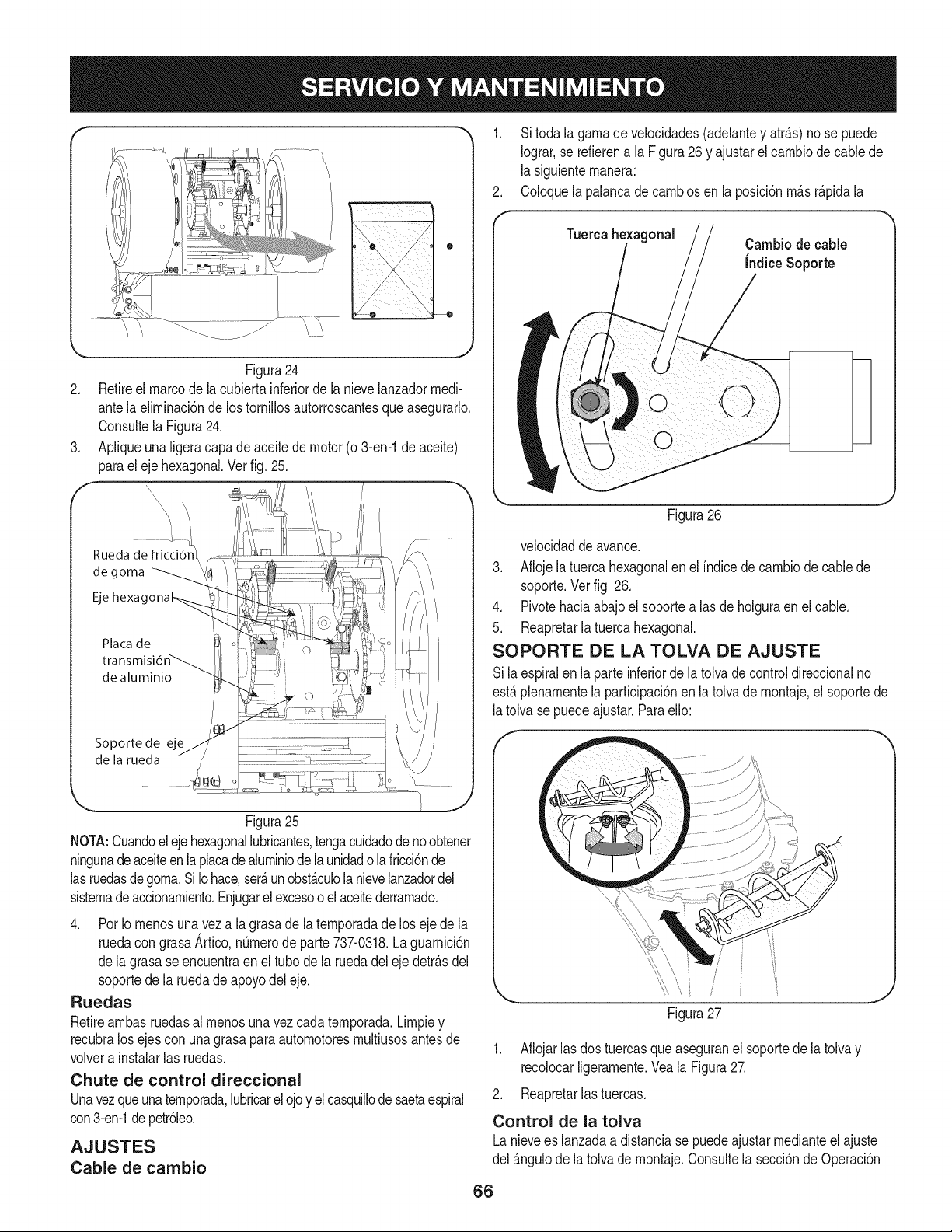
f
Figura24
2. Retireel marcode la cubiertainferiorde la nievelanzadorrnedi-
antela elirninaci6nde los tornillosautorroscantesqueasegurarlo.
Consultela Figura24.
3. Apliqueuna ligeracapade aceitede motor(o 3-en-1de aceite)
parael eje hexagonal.Ver fig. 25.
f ",
Rueda de fricci6n]_
de goma
Placa de
de aluminio
Soporte del eje
de la rueda
..,J
Figura25
NOTA:Cuandoel ejehexagonallubricantes,tengacuidadode no obtener
ningunadeaceiteen la placadealurniniode la unidado la fricci6nde
lasruedasdegorna.Si Iohace,serfiun obstficulola nievelanzadordel
sisternade accionarniento.Enjugarel excesooelaceitederrarnado.
4. Por Io rnenosuna veza la grasade la ternporadade loseje de la
ruedacon grasaArtico,nOrnerode parte737-0318.La guarnici6n
dela grasase encuentraen eltubo dela ruedadel ejedetrfisdel
soportede la ruedadeapoyodel eje.
Ruedas
Retirearnbasruedasalrnenosunavez cadaternporada.Lirnpiey
recubralos ejescon unagrasaparaautornotoresrnultiusosantesde
volvera instalarlas ruedas.
Chute de control direccional
Unavezqueunaternporada,lubricarel ojoy el casquillode saetaespiral
con3-en-1depetr61eo.
AJUSTES
Cable de cambio
1. Si todala garnade velocidades(adelantey atrfis)no se puede
Iograr,se refierena la Figura26y ajustarelcarnbiode cablede
lasiguienternanera:
2. Coloquela palancade carnbiosen la posici6nrnfis rfipida la
Tuercahexagonal Cambiode cable
Indice Soporte
k
Figura26
velocidaddeavance.
3. Aflojela tuercahexagonalen el indicede carnbiode cablede
soporte.Vet fig. 26.
4. Pivotehaciaabajo el soportealas de holguraenel cable.
5. Reapretarlatuercahexagonal.
SOPORTE DE LA TOLVA DE AJUSTE
Sila espiralen la parteinferiorde latolvadecontroldireccionalno
estfi plenarnentela participaci6nen la tolvade rnontaje,el soportede
latolvase puedeajustar.Paraello:
,f "_,
\
Figura27
1. Aflojarlas dostuercasqueaseguranel soportede latolvay
recolocarligerarnente.Veala Figura27.
2. Reapretarlastuercas.
Control de la tolva
Lanievees lanzadaa distanciase puedeajustarrnedianteel ajuste
del fingulodela tolvade rnontaje.Consultela secci6nde Operaci6n
66
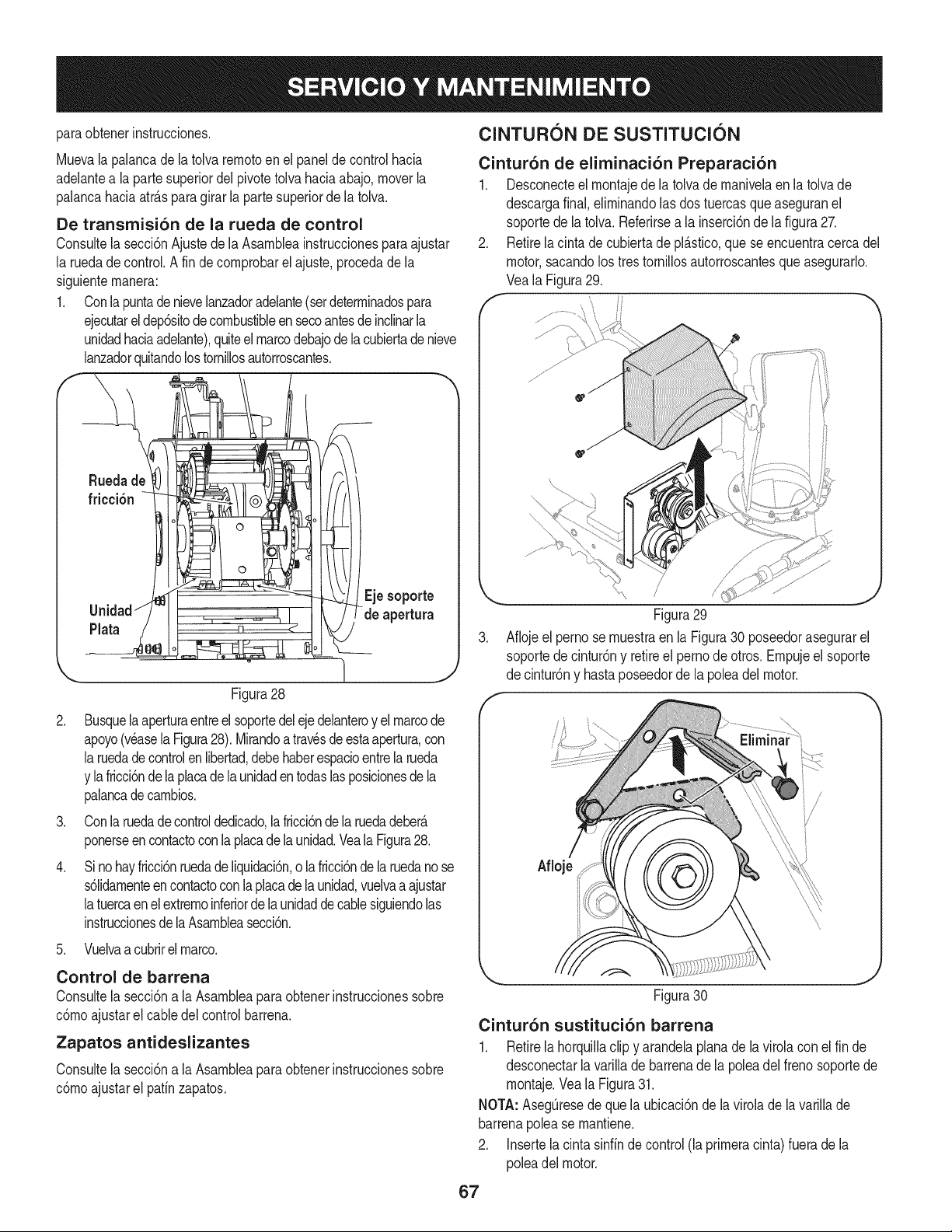
paraobtenerinstrucciones,
Muevala palancadela tolva rernotoen el panelde control hacia
adelantea laparte superiordelpivotetolvahaciaabajo,moverla
palancahaciaatr_.sparagirar la partesuperiorde la tolva.
De transmisi6n de la rueda de control
Consultela secci6nAjustede laAsambleainstruccionespara ajustar
la ruedadecontrol.A fin decornprobarel ajuste,procedade la
siguienternanera:
1. Conlapuntadenievelanzadoradelante(serdeterrninadospara
ejecutareldep6sitodecombustibleensecoantesde inclinarla
unidadhaciaadelante),quiteel marcodebajodela cubiertade nieve
lanzadorquitandolostornillosautorroscantes.
Ruedade
friccibn
Unidad
Plata
.
.
Ejesoporte
de apertura
Figura28
Busquela aperturaentreel soportedeleje delanteroy el marcode
apoyo(veasela Figura28).Mirandoa trav_sde estaapertura,con
laruedadecontrolen libertad,debehaberespacioentrela rueda
y lafricci6ndela placade la unidadentodaslasposicionesdela
palancadecarnbios.
Conlaruedadecontroldedicado,la fricci6nde la ruedadeber_
ponerseen contactoconla placade la unidad.Veala Figura28.
J
Sinohayfricci6nruedade liquidaci6n,o la fricci6nde la ruedanose
s61idarnenteencontactoconlaplacadelaunidad,vuelvaa ajustar
latuercaenel extrernoinferiordela unidaddecablesiguiendolas
instruccionesdela Asarnbleasecci6n.
5. Vuelvaa cubrirel marco.
Control de barrena
Consultela secci6na la Asarnbleaparaobtenerinstruccionessobre
c6rnoajustarel cabledel controlbarrena.
Zapatos antideslizantes
Consultela secci6na la Asarnbleaparaobtenerinstruccionessobre
c6rnoajustarel patfnzapatos.
ClNTUR6N DE SUSTITUCI6N
Cintur6n de eliminaci6n Preparaci6n
1. Desconecteel rnontajedela tolvade rnanivelaen latolvade
descargafinal,eNrninandolas dostuercasqueaseguranel
soportede la tolva.Referirsea la inserci6nde lafigura27.
2. Retirela cinta de cubiertade pl_.stico,quese encuentracercadel
motor,sacandolos trestorniNosautorroscantesqueasegurarlo.
Veala Figura29.
......................................i;!'
Figura29
3. Afiojeel perno sernuestraen la Figura30 poseedorasegurarel
soportede cintur6ny retireel pernodeotros. Ernpujeel soporte
de cintur6ny hastaposeedorde la poleadel motor.
f
Afloje
Figura30
J
Cintur6n sustituci6n barrena
1. Retirela horquillaclip y arandelaplanade la virolacon el fin de
desconectarla varillade barrenade la poleadel frenosoportede
rnontaje.Veala Figura31.
NOTA: AsegQresede quela ubicaci6nde lavirolade lavariNade
barrenapolease rnantiene.
2. Insertela cinta sinffnde control(la prirneracinta)fuera dela
poleadel motor.
67

clip
y arandela
,
Ferrul
/'
Rod polea )
Figura31
Tirela palancadelfreno haciael soportedernontajedelcable
guiade rodillosy desenganchedela barrenade cablez-rnontaje.
Veala Figura32.
Figura32
4. De arnbosladosdel bastidorde rnontaje,de utilizaci6nde 1 /2
"paraquitar laIlavehexagonalde toquetrestornillosquefijanel
marcode labarrenadelensarnblaje.Consultela Figura23, sobre
la anteriorenesta secci6n.
NOTA:No retireel bloqueode la bridainferiorde latuercahexagonal
encada lado.
5. Coloqueun bloquede rnaderadebajodela barrenade vivienda,
cornose rnuestraen la Figura33 y separadodela vivienda
barrenamarcoinclinandoel cuerpohaciaadelantey haciaabajo
enlas asas.
Figura33
6. Bloquearel irnpulsorcon un pedazode rnaderapara evitarque
el hiladoy el usode una1 /2 "paraquitar laIlavehexagonalde
tornilloy arandelaplanadesdeel centrode la poleasobrela
barrenavivienda.A veten la Figura34.
7. Levanteel soportede rnontajede frenode lapolearanura(B)
y deslicela poleaasarnbleafuerade los puestosde lapolea
del adaptadorde barrena(C) paraelirninarel antiguocintur6n.
Consultela Figura34.
NOTA:Eladaptadordela polea puededeslizarsefuerade la barrena
_.rbolal quitarla polea.Tengaespecialprecauci6nparaasegurarel
adaptadorse encuentrey /o obtenerdaSadoal retirarla polea.
Coloquelanuevacintade barrenaen la V-ranurade la polea barrena
y el lugarde lapolea con lacorreaenel interiordel cintur6nde
rnantenirniento.
Frenodisco ...
Adaptador
puesto
la polea
Figura34
Girea la poleaque seanecesarioparaalinearsus tres ranuras
de aproxirnadarnentecon los puestosdela poleadel adaptador
y,a continuaci6n,gireel soportede frenode rnontajefuerade la
ranurade la polea.
68
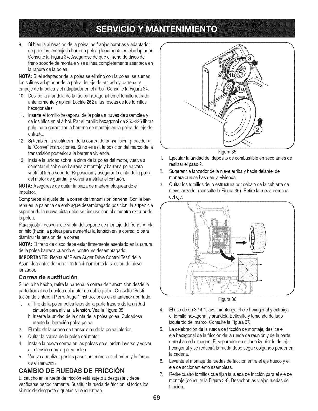
9. Si bien la alineaci6nde la polea lasfranjashorariasy adaptador
de puestos,ernpujela barrenapoleaplenarnenteen el adaptador.
Consultela Figura34. AsegOresede queel frenodediscode
frenosoportede rnontajey sealinea cornpletarnenteasentadaen
la ranuradela polea.
NOTA:Si eladaptadorde lapoleaseelirnin6con lapolea,se surnan
los splinesadaptadorde la poleadeleje deentraday barrena,y
ernpujede la poleay el adaptadoren el _.rbol.Consultela Figura34.
10. Deslicelaarandelade la tuercahexagonalen el tornilloretirado
anteriorrnentey aplicarLoctite262alas roscasde lostornillos
hexagonales.
11. Inserteel tornillohexagonalde la polea a travesde asarnbleay
de loshilosen el _.rbol.Parel tornillohexagonalde250-325 libras
pulg.paragarantizarla barrenade rnontajeen la polea del eje de
entrada.
12. Sitarnbi_nla sustituci6nde la correade transrnisi6n,procedera
la"Correa"instrucciones.Sino es asi, la posici6ndel marcode la
transrnisi6nposteriora la barrenavivienda.
13. Instalelaunidadsobrela cinta de la poleadel motor,vuelvaa
conectarel cablede barrenaz rnontajey barrenapoleavara
virolaalfreno soporte.Reposici6ny asegurarla cintade lapolea
delmotorde guardia,y volvera instalarel cintur6n.
NOTA:Aseg_resedequitarla piezade rnaderabloqueandoel
irnpulsor.
Cornpruebeel ajustede la correade transrnisi6nbarrena.Conla bar-
renaen la palancade ernbraguedesernbragadoposici6n,la superficie
superiorde lanuevacintadebeser inclusocon eldi_.rnetroexteriorde
la polea.
Paraajustar,desconecteviroladel soportede rnontajedelfreno.Virola
en hilo(hacialapolea)paraaurnentarla tensi6nen la correa,o para
disrninuirla tensi6ndela correa.
NOTA: Elfreno dediscodebeestar firrnernenteasentadoen la ranura
de lapoleabarrenacuandoel controles desernbragado.
IMPORTANTE:Repitael "PierreAugerDriveControlTest"de la
Asarnbleaantesde poneren funcionarnientola secci6nde nieve
lanzador.
Correa de sustituci6n
Si noIo hahecho,retirela barrenalacorreadetransrnisi6ndesdela
partefrontalde la poleadelmotor de doble polea.Consulte"Susti-
tuci6nde cintur6nPierreAuger"instruccionesenel anteriorapartado.
1. a. Tirede la poleapolea lejosde la partetraserade la unidad
cintur6nparaaliviar latensi6n.Vea la Figura35.
b. Insertelaunidadde lacintade la poleapolea.Cuidadosa
rnentela liberaci6npoleapolea.
2. El foliode la correade transrnisi6nde la poleainferior.
3. Quitarla correade la polea del motor.
4. Instalela nuevacorreaen las poleasen el orden inversoy volver
a latensi6ncon la poleapolea.
5. Vuelvaa realizarpor lospasosanterioresen el ordeny la forrna
deelirninaci6n.
CAMBIO DE RUEDAS DE FRICCION
Elcauchoen la ruedadefricci6nest&sujetoa desgastey debe
verificarseperi6dicarnente.Sustituirla ruedade fricci6n,si todoslos
signosdedesgasteo grietas seencuentran.
f
1.
2.
3.
f
69
J
Figura35
Ejecutarla unidaddeldep6sitode combustibleen seco antesde
realizarel paso2.
Sugerencialanzadorde la nievearribay haciadelante,de
rnaneraque se basaenla vivienda.
Quitarlos tornillosdela estructurapot debajode la cubiertade
nievelanzador_consultela Figura36). Retirela ruedaderecha
del eje.
Figura36
4. El usode un 3 /4 "Llave,rnantengael eje hexagonaly extraiga
el tornillohexagonaly arandelaBellevilley teniendode lado
izquierdodel marco.Consultela Figura37.
5. La celebraci6nde la ruedade fricci6nde rnontaje,desliceel
eje hexagonalde la fricci6nde la ruedade reuni6ny de la parte
derechadela irnagen.El separadoren el lado izquierdodel eje
hexagonaly se reducir_,la ruedadebeseguircolgandoperderen
la cadena.
6. Levanteel rnontajede ruedasde fricci6nentreel eje huecoy el
eje deaccionarnientoasarnbleas.
7. Retirecuatro tornillosque fijan la ruedade fricci6npara el eje de
rnontaje(consultela Figura38). Desecharlas viejasruedasde
fricci6n.

Q_uitelatuerca hexagonal de
brnillo y arandelaBelleville
Ruedadefricci6nAsarnblea
/
Figura37
¸ ¸ i
Figura38
8. Vuelvaa la nuevaruedade fricci6nen el centrode reuni6n,el
endurecirnientode los cuatrotornillosen larotaci6ny con la
rnisrnafuerza. Esirnportantereunirla ruedadefricci6nparael
buenfuncionarnientosirn_tricarnente.
9. Reposicionarel rnontajede la ruedadefricci6nenla nieve
lanzadormarco.Inserteel pasadorde la evolucbn del brazode
rnontajeen la ruedade fricci6nde reuni6ny de rnantenerenla
posici6ndernontaje.Consultela Figura39.
©
Figura39
10. Desliceeleje hexagonala trav_sde la partederechade la irnagen
haciaelladoizquierdoy porel rnontajede ruedasde fricci6n.
11. Despu_sde hacerla certezade que la cadenaesta en los
grandesy los peque_osrueda,ajustarel ejehexagonalhexago-
nalconel ejede la ruedapeque_a,y desliceel ejea travesdela
rueda.
NOTA:Si la ruedacay6del lanzadordela nievernientrasse quitael
eje hexagonal,el lugarde la ruedade lacadena. Reajustarla rueda
de lacadenahexadecimalcon el centroa la derechade la unidad.
Coloqueel eje hexagonalde la rueda haciala fricci6nde desliza-
rnientode la ruedacuandose ruedaenel eje hexagonal.
12. Desliceelespaciadorsobreel finaldel ejehexagonal.
NOTA:Elseparadores para ser puestosen el ejehexagonalentre
larueday teniendopreviarnenteelirninadoen ellado izquierdodel
marco.
13. Alineeel rodarnientoen el extrernoderechodel eje hexagonal
con el agujero.
14. Enla partederechade la irnageny, a continuaci6n,pulseel eje
hexagonalhaciala izquierdaen la posici6nen el marco.
15. Deslicela presi6nenel extrernoizquierdodel eje hexagonaly
pulseen elagujeroen ellado izquierdodel marco.
16. ColoquelaarandelaBelleville(lado redondeadohaciala cabeza)
en eltornillohexagonalelirninadoconanterioridad,e insertarel
tornilloenel agujeroroscadodeleje hexagonal.
17. Pocoa poco aprieteel tornillohexagonalplenarnenteasientode
los rodarnientosencada ladodel marcoy paraasegurarel eje
hexagonal.
18. Coloqueel marcode cubriren laparte inferiordelmarcoy
asegurecon los tornillosautorroscantes.Pivotelanzadordela
nievea fin decuentasposici6nnormaldefuncionarniento.
7O

Sinosevaa utilizael equipodurante30dfasorn_.s,o sies elfinaldelaternporadadenievey ya noexisteposibilidaddequenieve,es necesario
alrnacenarelequipode rnaneraadecuada.Sigalasinstruccionesde alrnacenarnientoquese indicana continuaci6nparagarantizarel rendirniento
rn_.xirnodelarn_.quinaquitanieveduranternuchosa_os.
PREPARACI6N DEL MOTOR
Losrnotoresquese alrnacenandurantern&sde 30 dfas necesitan
serdrenadosdecombustiblepara evitarque se deterioreny se forrne
gornaenel sisternade combustibleo en las piezasprincipalesdel
carburador.Si lagasoNnade su motorse deterioraduranteel alrnace-
narniento,es posiblequedeba repararo reernplazarelcarburadory
otroscornponentesdel sisternade combustible.
1. Elirninetodoel combustibledel tanquehaciendofuncionarel
motorhastaquese detenga.No intentede combustibleparael
motor.
2. Carnbieel aceitedel motor.
3. Extraigala bujfade encendidoy viertaen elcilindroaproxirna-
darnente1onza(30 rnl)de aceiteparamotorNrnpio.Tire varias
vecesdel arrancadorde retrocesopara distribuirel aceite y
reinstalela bujfa.
4. Lirnpielos residuosde alrededordel motor,y debajo,alrededor,
y detr_.sdel silenciador.ApNqueunacapa delgadade aceiteen
todaslas _.reasquepuedenNegara oxidarse.
• Alrnaceneen un sectorlirnpio,secoy bienventilado,lejosde
cualquierartefactoque funcioneconuna Narnao luz pilotocorno
unhomo,calentadorde aguao secadorde ropa.Evitecualquier
sectorcon un motorel_ctricoqueproduzcachispaso dondese
utilicenherrarnientasel_ctricas.
Nuncaalrnacenelarn_.quinaquitanieveconcombustibleen el
tanqueenun espaciocerradooen _.reascon pocaventilaci6n,
dondelosgases del combustiblepuedanalcanzarel fuego,chispas
o unaluz pilotocornola quetienenalgunoshornos,calentadoresde
agua,secadoresde ropa o algQnotto dispositivoa gas.
PREPARACI6N DE LA NIAQUINA QUITANIEVE
1. Cuandoalrnacenelarn&quinaquitanieveen ungalp6nde
dep6sitornet_.licoo con pocaventilaci6n,tengaespecialcuidado
de realizarleuntratarnientoanti- oxidanteal equipo.Useaceite
ligeroo silic6npararecubrirel equipo,especialrnentelas
cadenas,los resortes,loscojinetesy loscables.
2. Elirninetodo el polvodel exteriordelmotory del equipo.
3. Siga las recornendacionesde lubricaci6nen la secci6nde
rnantenirnientodeestemanual.
4. AIrnaceneel equipoen un _.readespejaday seca.
5. Inflarlos neurn_.ticosa la presi6nde psi rn_.xirna.Consulteel
costadodelneurn_.tico.
• Sies posible,evitesectoresde alrnacenarnientocon rnucha
hurnedad.
• Mantengael motorniveladoen el alrnac_n.La inclinaci6ndel
motorpuedecausarperdidasde combustibleo aceite.
71

Elmotornoarranca 1. La palancadeobturaci6nnoest,.enla
posici6nON (encendido)
2. Se ha desconectadoel cablede la bujia
3. La bujia nofunciona correctamente
4. El tanquede combustibleest,. vado o el
combustibleesviejo
5. El motorno est,. cebado
6. La Ilaveno se encuentraen el encendido
delmotor
7. Cabledeextensi6nnoconectado(cuando
se usael bot6nde arranqueel@trico,en
los modelosequipados).
1. Pongael interruptoren la posici6nCHOKE(obtura-
ci6n).
2. Conecteel cablea la bujfa.
3. Limpie,ajustela distanciadisruptivao cambie.
4. Lleneel tanquecongasolinalimpiay fresca.
5. Cebeel motortal y como se indicaen lasecci6nde
operaci6n.
6. Insertela Ilavetotalmentedentrodel interruptor.
7. Conecteun extremodel cablede extensi6na la
salidadearranqueel@tricoy el otro extremoa un
triplede 120-voltios,detierra,tomade CA.
Elmotorfuncionademanera
err_.tica
1. La unidadest,. funcionandoen laposici6n
CHOKE(obturaci6n)
2. EIcombustibleesviejo
3. Aguao suciedaden el sistemadel combus-
tible
4. M_.sgobernadosmotor
1. Cambiela palancade obturaci6na la posici6nOFF
(apagado).
2. Lbne el tanquecongasolinalimpiay fresca.
3. Drenarel tanquede combustibleen el motoren
marchahastaque sedetenga.Vuelvaa Ilenarlocon
combustiblelimpio.
4. Contactecon su centrode partesy reparaciones
Sears.
zNECESITA MAS AYUDA?
_!ncor_V:r_r5 b I_e i_uu v:_y m_ en managemylife.com _ isin cargo!
En linea podr3 encontrar este manual y los manuales de todos los otros productos que posea,
Sus preguntas ser_n respondidas pot nuestro equipo de especialistas,
Obtenga un plan de rnantenimiento personalizado para su hogar,
Encuentre informaciOn y herramientas que Io ayudar_n con los proyectos de su hogar,
managemyHfe
72
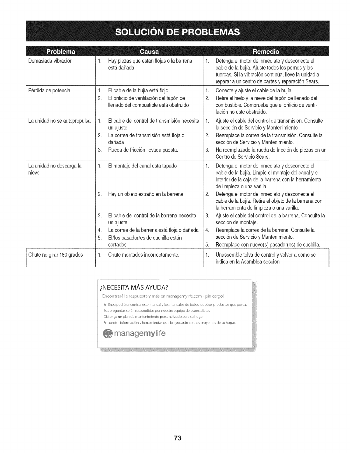
Dernasiadavibraci6n 1. Haypiezasqueest_.nfiojas o la barrena
est,.dafiada
1. Elcable dela bujfaest,.flojo
2. El orificio de ventilaci6ndel tap6nde
Ilenadodelcombustibleest,. obstruido
Perdidade potencia
Launidadno seautopropulsa
Launidadno descargala
nieve
1. Elcable delcontroldetransrnisi6nnecesita
unajuste
2. La correade transrnisi6nest,. floja o
da_ada
3. Ruedadefricci6nIlevadapuesta.
1. Elrnontajedelcanalest,. tapado
2. Hay un objetoextra_oen la barrena
3. El cable del controlde la barrenanecesita
unajuste
4. La correade la barrenaest,. flojao da_ada
5. El/lospasador/esdecuchillaest_.n
cortados
1. Detengael motorde inrnediatoy desconecteel
cablede la bujia.Ajustetodoslos pernosy las
tuercas.Sila vibraci6ncontinQa.Ilevela unidada
reparara uncentrode partesy reparaci6nSears.
1. Conectey ajusteel cablede la bujfa.
2. Retireel hieloy la nievedel tap6nde Ilenadodel
combustible.Cornpruebeque el orificiode venti-
laci6nnoest_obstruido.
1. Ajusteel cabledelcontrolde transrnisi6n.Consulte
la secci6nde Servicioy Mantenirniento.
2. Reernplacela correade la transrnisi6n.Consultela
secci6nde Servicioy Mantenirniento.
3. Ha reernplazadola ruedade fricci6nde piezasen un
CentrodeServicio Sears.
1. Detengael motorde inrnediatoy desconecteel
cablede la bujia.Lirnpieel rnontajedelcanaly el
interiorde la cajade labarrenacon laherrarnienta
de lirnpiezao unavarilla.
2. Detengael motorde inrnediatoy desconecteel
cablede la bujia.Retireelobjetode la barrenacon
la herrarnientade lirnpiezao una varilla.
3. Ajusteel cabledel controlde la barrena.Consultela
secci6nde rnontaje.
4. Reernplacela correade la barrena Consultela
secci6nde Servicioy Mantenirniento.
5. Reernplacecon nuevo(s)pasador(es)de cuchilla.
Chuteno girar 180grados 1. Chuternontadosincorrectarnente. 1. Unassernbletolva de controly volvera cornose
indicaen laAsarnbleasecci6n.
73

74

75

MTD CONSUMER GROUP, iNC. (MTD), el Bordo de Recursos de Aire de California (CARB)
y la Agencia de Protecci6n Medioambiental de Estados Unidos (U. S. EPA)
Declaraci6n de Garantia del Sistema de Control de Emisiones
(Derechos yobligaciones del propietario seg_n la garantia contra defectos)
LACOBERTURADESISTEMADECONTROLDEEMISIONESAPLICABLEA MOTORESCERTIFICADOSCOMPRADOSENCALIFORNIA
EN2005Y A PARTIRDE ENTONCES,QUESON USADOSEN CALIFORNIA,Y HASTAANO2005 DE MODELOCERTIFICADOY MOTORES
POSTERIORESQUESON COMPRADOSY USADOSENOTRAPARTEEN LOSESTADOSUNIDOS.
Californiayen otraparteen la Coberturade Garantiade DefectosdeControlde Emisi6nde los EstadosUnidos
El Bordode Recursosde Airede California(CARB),la U.S. EPAy MTDsecomplacenenexplicarla garantiadel sistemade controldeemisiones
de su motorparaequipotodo terreno,modelo,aSo2005y versionesposteriores.En California,los nuevosmotorespequeSosparaequipotodo
terrenose debendise5ar,fabricary equiparparacumplirconest_.ndaresde antinieblat6xicade estados.Enotraparteen los EstadosUnidos,
el nuevonocamino,motoresdeignici6ndechispacertificadosparaelmodelo2005y m_.starde,debe encontrarel juego de est_.ndaressimilar
adelanteporlos EstadosUnidos.EPA.MTDdebegarantizarel sistemadecontrolde emisionesdesu motorpor elperiodode tiempoindicadom&s
abajo,siemprey cuandono hayaexistidousoincorrecto,negligencianimantenimientoinadecuadode su motorpequeBoparaequipotodoterreno.
El sistemadecontrolde emisionespuedeincluirpiezascomo,por ejemplo,el carburador,sistemade inyecci6nde combustible,el sistemade
encendido,el catalizador,losdep6sitosdecombustible,abastecede combustiblelineas, gorrasde combustible,v&lvulas,latas,filtros,mangueras
devapor,abrazaderas,conectoresy otroscomponentesrelacionadosconlas emisiones.
Dondeexistaunacondici6ncubiertapor la garantia,MTDreparar&su motorpequeBoparaequipotodoterrenosincostoalguno incluyendoel
diagn6stico,laspiezasy la manode obra.
COBERTURA DE LA GARANTJA DEL FABRICANTE:
Estesistemade controldeemisionesse garantizaporel t@rminodedos a5os.Si algunapiezade su motorrelacionadacon lasemisioneses
defectuosa,MTD reparar&o sustituir&dichapieza.
RESPONSABJLIDADES DEL PROPIETARIO SEGUN LA GARANTJA:
Comopropietariodeun motorpequeSode equipotodoterreno,ustedes responsablede realizarel mantenimientonecesarioquefigura en el
manualdel propietario.MTDle recomiendaqueconservetodoslos recibosquecubrenlos serviciosdemantenimientodel motorpeque5opara
equipotodoterreno,noobstanteIo cual MTDno podr&denegarel cumplimientode la garantiaQnicamenteporla falta de reciboso porsu imposibi-
lidadde asegurarquese realizar_.ntodoslos serviciosdemantenimientoprogramado.
Comopropietariodelmotorpeque5oparaequipotodo terreno,sinembargo,ustedtambi@ndebesaberque MTDpuededenegarlacoberturadela
garantiasi su motorpeque5oparaequipotodoterrenoo unapiezadel mismofallandebido a usoincorrecto,negligencia,mantenimientoindebido
oa modificacionesno aprobadas.
Ustedes responsablede presentarlacortadoradecespedal centrode distribuci6no de mantenimientode MTDCONSUMERGROUP,INC. tan
prontocomoaparecierael problem& Lasreparacionescubiertaspor lagarantfasedebenIlevaracabo enun lapsorazonableque noexcedade
30dias. Si desearealizaralgunaconsultacon respectoa la coberturade la garantia,debeponerseencontactocon su distribuidorlocalde MTD.
Paracomunicarseconla Lineade Asistenciaal Clientede Distribuidoresde MTD,Ilameal nQmero(877)282-8684.
REQUERJMJENTOS DE GARANTJA SOBRE DEFECTOS PARA MOTORES PEQUENOS DE EQUJPO TODO TERRENO
DE 1995YVERSJONES POSTERJORES:
Estasecci6nse aplicaa motorespeque5osdeequipotodo terrenode 1995y versionesposteriores.Elperiododegarantiacomienzaa partirde la
fechaen queel motoro el equipo seentreganal compradorfinal.
(a)Coberturade la garantiacontraemisionesgenerales
MTDgarantizaal compradorfinaly acada compradorsubsiguientequeel motor:
(1)hasido diseSado,construidoy equipadode maneraque cumplacontodas las regulacionesvigentesadoptadaspor el Departamentode los
RecursosdeAire en virtud a suautoridadconferidaen los capitulos1y 2, Parte5, Divisi6n26del C6digode Saludy Seguridad;y
(2)est,. librede defectosen los materialesyen la manode obra quecausenlafalla de una piezabajogarantiaque seaid@nticaentodos los
aspectosmaterialesa lapiezacomoaparecedescriptaen laaplicaci6ndelfabricantedel motorparacertificaci6npor unperiododedos a5os.
Lb/Lagarantiasobre piezasrelacJonadasconemisJonesse interpretar_,de la sJguientemanera:
(1)Cualquierpiezacubiertapor garantiaque no est@programadaparasu reemplazosegQnel mantenimientorequeridoenlas instrucciones
escritasdela Subsecci6n(c) debeestargarantizadapor un periodode garantiadefinidoen la Subsecci6n(a) (2). Si la piezafalladurante
el periododecoberturade la garantia,la mismaser_.reparadao reemplazadapor MTD de acuerdocon la Subsecci6n(4) a continuaci6n.
Cualquierpiezareparadao reemplazadasegQnla garantiasegarantizarB,por el resto del periodode garantia.
(2) Cualquierpiezacubiertaporgarantiaque est@programadasoloparainspecci6nregularen las instruccionesescritasde la Subsecci6n
(c) debeestargarantizadapor un periododegarantiadefinidoen la Subsecci6n(a) (2). Unadeclaraci6nen dichasinstruccionesporescrito
alefectode "reparaci6no reemplazosegQnseanecesario"no reducir_,el periodode coberturade la garantia.Cualquierpiezareparadao
reemplazadasegQnla garantiase garantizar_,porel restodel periodode garantia.
(3) Cualquierpiezagarantizadaqueest_prograrnadaparareernplazosegQnelrnantenirnientorequeridodeconforrnidadconlasinstruc-
clonesescritasdelaSubsecci6n(c)segarantizaporelperiododetiernpoanterioralaprirnerafechadereernplazoprograrnadaparaesa
pieza.Silapiezafallaantesdelprimerreernplazoprogramatic,larnisrnaser_.reparadaoreernplazadaporMTDdeacuerdoconlaSubsecci6n
(4)acontinuaci6n.Cualquierpiezareparadaoreernplazadabajogaranfiasegarantizar_,porelrestodelperiodoanterioralprimerreernplazo
programaticpuntualparaesapieza.
(4)Lareparaci6noelreernplazodecualquierpiezagarantizadadeconforrnidadconlasdisposicionesdelagaranfiaqueaquiseestipulase
deberealizarenuncentrodegaranfiasincostoalgunoparaelpropietario.
(5)SinperjuiciodelasdisposicionesdelaSubsecci6n(4)anterior,losservicioso reparacionescubiertosporlagaranfiadebensersurnin-
istradosportodosloscentrosdedistribuci6ndeMTDquetenganlafranquiciapararealizarreparacionesyrnantenirnientoalosrnotoresen
cuesti6n.
(6)ElpropietarionodebeafrontarningQncargoparatrabajosdediagn6sticoqueIlevenalaconclusi6ndequeunapiezabajogaranfiapresenta
efectivarnentedefectos,siernpreycuandodichodiagn6sticoseaIlevadoacaboenuncentrocubiertoporlagarantia.
(7)ElfabricantedelmotoresresponsablepordaSoscausadosaotroscornponentesdernotoresderivadosdelafallabajogaranfiadecualquier
piezagarantizada.
(8)DurantetodoelperiododegaranfiadelmotordefinidoenlaSubsecci6n(a)(2),MTDrnantendr_,unsurninistrodepiezascubiertaspor
garantiasuficienteparasatisfacerladernandaesperadaparatalespiezas.
(9)Cualquierpiezadereernplazosepodr_,usarparaelcurnplirnientodelrnantenirnientoo reparacionesbajogaranfia,ysesurninistrar_,sin
cargoalpropietario.Dichousonoreducir_,lasobligacionesdegarantiadeMTD.
(10)Nosepodr_.nusarpiezasadicionalesnirnodificadasquenoest_nexentasdeacuerdoconelDepartarnentodelosRecursosdelAire(Air
ResourcesBoard).Elusodepiezasadicionalesornodificadasnoexentasser_.causasuficienteparaanularunreclarnobajogaranfiarealizado
deacuerdoconestearticulo.Elfabricantedelmotornotendr_,responsabilidad,enconforrnidadconestearticulo,degarantizarfallasdepiezas
garantizadasquefuerencausadasporelusodeunapiezanoexentaadicionalornodificada.
.(c)MTDincluir_,unacopiade lasiguientelistade piezasbajogarantiacontraernisionescon cadanuevomotor,utilizandolas partesde la lista
a_plicablesal motor.
(1)Sisternadernedici6nde combustible
• Sisternade rnejoraparainicioen frio (cebadosuave)
• Carburadory cornponentesinternos
• Bornbade combustible
• Dep6sitodecombustible
(2) Sisternadeinducci6nde aire
• Filtrode aire
• Colectordeentrada
(3) Sisternadeencendido
• Bujia(s)
• Sisternadeencendidopor magneto
(4)Sisternadeescape
• Catalizador
• SAI (v_Jvulade CaSa)
(5) Cornponentesvarios utilizadosen el sisternaanterior
• V_Jvulase interruptoresde vado, ternperatura,posici6nsensiblesal tiernpo
• Conectoresy rnontajes
(6)Controlde Evaporative
• Manguerade CombustiblecertificadaparaARB evaporativeernisi6nde 2006.
• Abrazaderasde Manguerade Combustible
• Gorrade combustibleatada
• Latade carb6n
• Lineasdevapor
GD0C-100174Rev.B
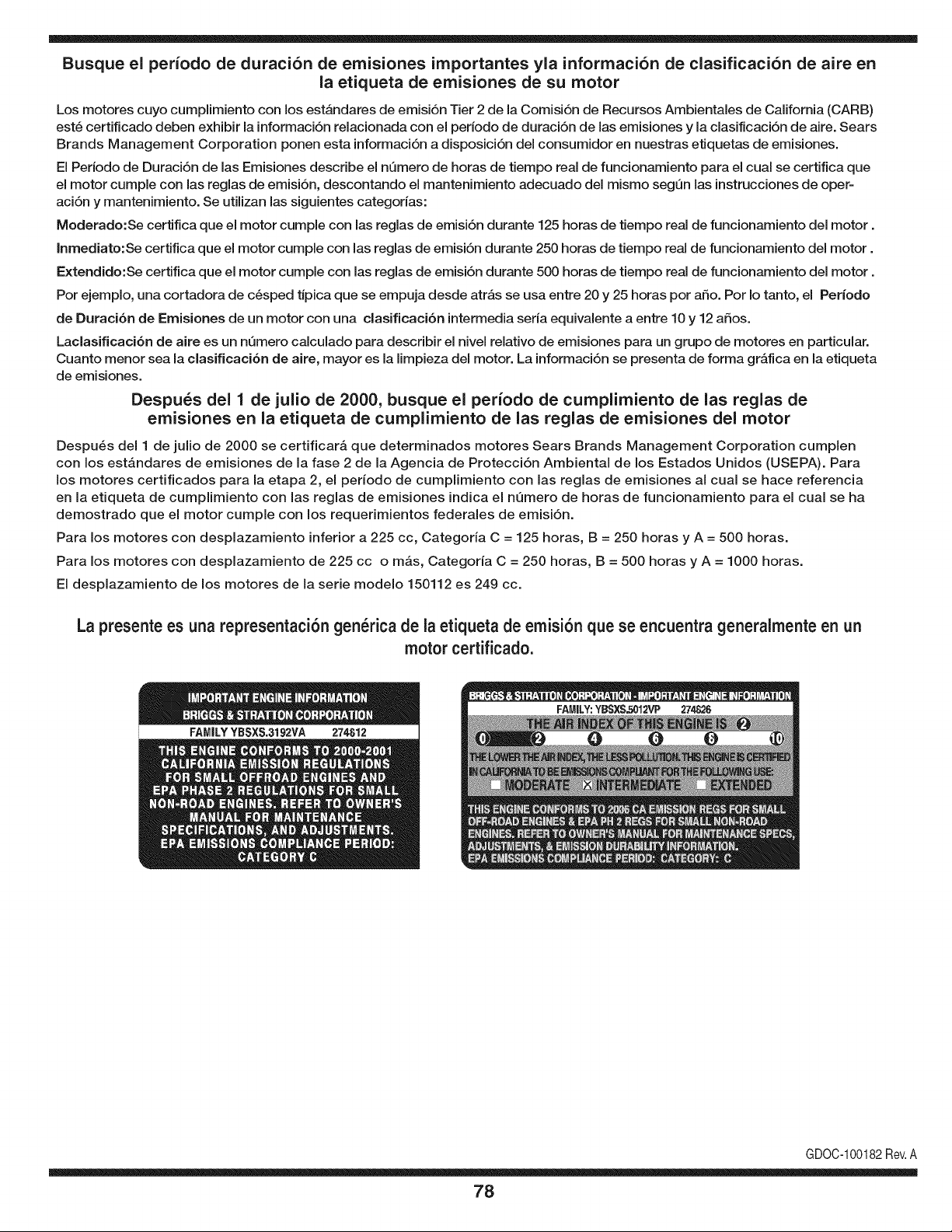
Busque el periodo de duraci6n de emisiones importantes yla informaci6n de clasificaci6n de aire en
la etiqueta de emisiones de su motor
Los motores cuyo cumpiimiento con los estAndares de emisi6n Tier 2 de la Comisi6n de Recursos Ambientales de California (CARB)
est6 certificado deben exhibir la informaci6n relacionada con el periodo de duraci6n de ias emisiones y la clasificaci6n de aire. Sears
Brands Management Corporation ponen esta informaci6n a disposici6n del consumidor en nuestras etiquetas de emisiones.
Ei Periodo de Duraci6n de las Emisiones describe el nQmero de horas de tiempo real de funcionamiento para el cuai se certifica que
el motor cumpie con ias reglas de emisi6n, descontando el mantenimiento adecuado del mismo segQn las instrucciones de oper-
aci6n y mantenimiento. Se utilizan las siguientes categonas:
Moderado:Se certifica que el motor cumpie con las reglas de emisi6n durante 125 horas de tiempo real de funcionamiento del motor.
Inmediato:Se certifica que el motor cumpie con las reglas de emisi6n durante 250 horas de tiempo real de funcionamiento del motor.
Extendido:Se certifica que el motor cumpie con las reglas de emisi6n durante 500 horas de tiempo real de funcionamiento del motor.
Por ejemplo, una cortadora de c6sped tJpica que se empuja desde arras se usa entre 20 y 25 horas por aSo. Por Io tanto, el Periodo
de Duraci6n de Emisiones de un motor con una clasificaci6n intermedia sena equivaiente a entre 10 y 12 aSos.
Laciasificaci6n de aire es un nQmero calculado para describir el nivel relativo de emisiones para un grupo de motores en particular.
Cuanto menor sea la clasificaci6n de aire, mayor es la limpieza del motor. La informaci6n se presenta de forma grAfica en la etiqueta
de emisiones.
Despu_s del 1 de julio de 2000, busque el periodo de cumplimiento de las reglas de
emisiones en la etiqueta de cumplimiento de las reglas de emisiones del motor
Despu6s del 1 de julio de 2000 se certificarA que determinados motores Sears Brands Management Corporation cumplen
con los estAndares de emisiones de la fase 2 de la Agencia de Protecci6n Ambientai de los Estados Unidos (USEPA). Para
los motores certificados para la etapa 2, el periodo de cumplimiento con ias reglas de emisiones al cual se hace referencia
en la etiqueta de cumplimiento con las reglas de emisiones indica el nQmero de horas de funcionamiento para el cual se ha
demostrado que el motor cumple con los requerimientos federales de emisi6n.
Para los motores con desplazamiento inferior a 225 cc, Categoria C = 125 horas, B = 250 horas y A = 500 horas.
Para los motores con desplazamiento de 225 cc o mAs, Categoria C = 250 horas, B = 500 horas y A = 1000 horas.
El desplazamiento de los motores de la serie modelo 150112 es 249 cc.
La presente es una representaci6n gen_rica de la etiqueta de emisi6n que se encuentra generaimente en un
motor certificado.
FAMILYYBSXS.3192VA 274812
GDOC-100182Rev.A
78
Felicitaciones por haber realizado una adquisici6n inteligente. El producto Craftsman® que ha
adquirido esta diseSado y fabricado para brindar muchos aSos de funcionamiento confiable. Pero
como todos los productos a veces puede requerir de reparaciones. Es en ese momento cuando el
disponer de un Acuerdo de protecci6n para reparaciones le puede ahorrar dinero y problemas.
A continuaci6n se detallan los puntos incluidos en el Acuerdo:
[] Servicio experto prestado por nuestros 10,000 especialistas en reparaciones profesionales
[] Servicio ilirnitado sin cargo para las piezas y la mano de obra en todas las reparacionescubiertas
[] Reernplazo del producto hasta 1500 d61aressi no es posible reparar el producto cubierto
[] Descuento de 25% del precio normal del servicio y de las piezas relacionadas con el mismo que no esten cubiertas
por el acuerdo; ademas, 25% del precio normal de la verificaci6n de mantenimientopreventivo
[] Ayuda r_pida pot tel_fono - Io IlamamosResoluci6n RApida- el apoyo telef6nico de un Chamusca al representante.
Piense en nosotros como el manual "de un dueSo hablador."
Una vez adquirido el Acuerdo, puede programar el servicio con tan s61orealizar una Ilamadatelef6nica. Puede Ilamar en
cualquier momento del dia o de la noche o programar un servicio en linea.
ElAcuerdo de Protecci6nde Reparaci6nes una compra sin riesgo. Si usted anula por alguna raz6n durante el periodo de
garantia de producto, proporcionaremos un reembolso Ileno.O, un reembolso prorrateado en cualquier momento despues
del periodo de garantia de producto expira, iAdquiera hoy su acuerdode protecci6n para reparaciones!
Se aplican determinadas limitaciones y exclusiones. Para obtener informaciTn adicional y precios en los Estados
Unidos Ilame al 1-800-827-6655.
El *Coverage en Canad_ivaria en algunos articulos. Para detalles Ilenos la Ilamada Chamusca Canad_ien 1-800-
361-8885.
Servicio de instalaci6n de Sears
Si desea solicitar la instalaci6n profesionalde Sears de aparatosdomesticos, dispositivos paraabrir portones, calentado-
res de agua y otros articulos domesticos importantes, en los Estados Unidos o Canada flame al 1-800-4-MY-HOME®.
79

Your Home
For troubleshooting, product manuals and expert advice:
managernylife
www.managemylife.com
For repair - in your home - of all major brand appliances,
lawn and garden equipment, or heating and cooling systems,
no matter who made it, no matter who sold it!
For the replacement parts, accessories and
owner's manuals that you need to do-it-yourself.
For Sears professional installation of home appliances
and items like garage door openers and water heaters.
1-800-4-MY-HOME ®(1-800-469-4663)
Call anytime, day or night (U.S.A. and Canada)
www.sears.com www.sears.ca
Our Home
For repair of carry-in items like vacuums, lawn equipment,
and electronics, call anytime for the location of your nearest
Sears Parts & Repair Service Center
1-800-488-1222 (U.S.A.) 1-800-469-4663 (Canada)
www.sears.com www.sears.ca
To purchase a protection agreement on a product serviced by Sears:
1-800-827-6655 (U.S.A.) 1-800-361-6665 (Canada)
Para pedir servicio de reparaci6n
a domicilio, y para ordenar piezas:
1-888-SU-HOGAR ®
(1-888-784-6427)
www.sears.com
Au Canada pour service en frangais:
1-800-LE-FOYER Mc
(1-800-533-6937)
www.sears.ca
® Registered Trademark /TMTrademark of KCD IP, LLC in the United States, or Sears Brands, LLC in other countries
® Marca Registrada !TMMarca de Fabrica de KCD IP, LLC en Estados Unidos, o Sears Brands, LLC in otros paises
MCMarque de commerce !MDMarque deposee de Sears Brands, LLC