

Read all safety rules and instructions carefully before operating this tool.
Owner’s Manual
TOLL-FREE HELPLINE: 1-888-90WORKS
(888.909.6757)
7-1/2″ ELECTRIC LAWN EDGER
27032
www.greenworkstools.com
P0802368-01 Rev B1

2
Contents .............................................................................................................................. 2
......................................................................................................... 2
Important Safety Instructions ............................................................................................3 -5
........................................................................................................... 6
Symbols ............................................................................................................................8 -9
Electrical ....................................................................................................................... 10-11
Know your Lawn Edger....................................................................................................12
Assembly ...................................................................................................................... 13-16
Operation .......................................................................................................................17-21
Maintenance ................................................................................................................. 22-24
Troubleshooting ................................................................................................................. 2 5
Warranty ............................................................................................................................ 2 6
Exploded View .............................................................................................................. 27-29
PRo Du CT SPECIf ICATIo NS
7-1/2″
ELECTRIC LAWN EDGER ...................................................................................
Input .............................................................................. 120 V, AC only, 60 Hz, 12 Amps
Blade Length ...............................................................................................7-1/2″.(19cm)
Weight ........................................................................................................14 lb (6.3 kg)
Co NTENTS
YEAR
AÑOS
LIMITED WARRANTY
GARANTÍA
LIMITADA
3

3
IMPoRTANT SAfETY INSTRuCTIoNS
W a R N I N g
Read and understand all instructions. failure to follow all instructions listed below may result in
electric shock, re and/or serious personal injury.
• Read the operator’s manual carefully. Be thoroughly familiar with the controls and the proper
use of the equipment. Know how to stop the unit and disengage the controls quickly.
• Do not allow children or untrained individuals to use this unit.
• Clear the work area before each use. Remove all objects such as rocks, broken glass, nails,
wire, or string which can be thrown or become entangled in the edger blade.
• Wear safety glasses or goggles that are marked to comply with ANSI Z87.1 standard when
operating this product.
• Dress properly — Do not wear loose clothing or jewelry. They can be caught in moving parts.
use of sturdy gloves is recommended. use of rubber gloves and substantial footwear is
recommended when working outdoors. Wear protective hair covering to contain long hair.
• Do not operate product when barefoot or wearing open sandals. Always wear safety footwear
and pants or slacks that cover your legs.
• Never operate this unit on the operator’s left side.
• Keep children, bystanders, and pets at least 50 ft. away. Bystanders should be encouraged to
wear eye protection. If approached, stop motor and attachment.
• Stay alert, watch what you are doing, and use common sense. Do not use product while tired
or under the inuence of drugs, alcohol, or medication.
• Do not operate in poor lighting.
• Keep rm footing and balance. Do not overreach. overreaching can result in loss of balance
or exposure to hot surfaces. Keep cutting attachment below waist.Keep all parts of your body
away from any moving part.
daNgER: ROTaTINg cUTTINg MEMBER.
• Keep both hands on handles when blade is rotating.
• Keep hands and feet away from cutting area.
• Do not attempt to remove cut material nor hold material to be cut when motor is running or
when cutting member is moving.
• Make sure unit is unplugged when clearing jammed material from cutting member.
• Keep guards in place.
• Keep blade clean and sharp. Replace dull blades as needed.
caUTION: cUTTINg MEMBER cOaSTS aFTER TURN OFF.
• unplug from the power outlet before making any adjustments or repairs. Wear protective
equipment and observe all safety instructions. When the unit is turned off, make sure the
cutting attachment has stopped before setting the unit down.

4
IMPoRTANT SAfETY INSTRuCTIoNS
• Inspect unit before each use for loose fasteners. Replace any damaged parts before use.
• Do not, under any circumstance, use any attachment or accessory on this product which
was not provided with the product, or identied as appropriate for use with this product in the
operator’s manual.
• Avoid dangerous environments. Do not use the product in damp or wet locations.
• Do not use in rain.
• If the product vibrates abnormally, immediately stop the motor and check for the cause.
Vibration is generally a warning of trouble.
• Before cleaning, repairing, or inspecting, shut off the motor and make certain all moving parts
have stopped.Service on the product must be performed by qualied repair personnel only.
Service or maintenance performed by unqualied personnel could result in injury to the user
or damage to the product.
• use only identical replacement parts when servicing the product. use of unauthorized parts
may create a risk of serious injury to the user, or damage to the product.
• To reduce the risk of electric shock, this tool has a polar-ized plug (one blade is wider than the
other) and will require the use of a polarized extension cord. The plug will t into a polarized
extension cord only one way. If the plug does not t fully into the extension cord, reverse
the plug. If the plug still does not t, obtain a correct polarized extension cord. A polarized
extension cord will require the use of a polarized wall outlet. This plug will t into the polarized
wall outlet only one way. If the plug does not t fully into the wall outlet, reverse the plug. If
the plug still does not t, contact a qualied electrician to install the proper wall outlet. Do not
change the equipment plug, extension cord receptacle, or extension cord plug in any way.
• Avoid body contact with grounded surfaces such as pipes, radiators, ranges, and
refrigerators.
• There is an increased risk of electric shock if your body is grounded.
• Don’t expose product to rain or wet conditions. Water entering a power tool will increase the
risk of electric shock.
• Do not handle plug or tool with wet hands.
• When operating a power tool outside, use an outdoor extension cord marked “W-A” or “W.”
These cords are rated for outdoor use and reduce the risk of electric shock.Store idle edger
indoors — when not in use store in dry, and high or locked up place out of reach of children.
• Turn off all controls before unplugging.
• Do not use tool if switch does not turn it on or off. Any tool that cannot be controlled with the
switch is dangerous and must be repaired.
• Do not use with damaged plug. If tool is not working as it should or has been dropped,
damaged, left outdoors, or dropped into water, return it to an authorized service center.
• Do not leave the tool when plugged in. unplug from the power outlet when not in use, before
servicing, changing accessories, and before storing the tool. Such preventative safety
measures reduce the risk of starting the tool accidentally.

5
IMPoRTANT SAfETY INSTRuCTIoNS
• Don’t Abuse Cord — Do not pull or carry by cord, use cord as a handle, close a door on a
cord, or pull cord around sharp edges or corners or yank to disconnect. Do not run appliance
over cord. Keep cord away from heated surfaces.
• Do not unplug by pulling on cord. To unplug, grasp the plug, not the cord.
• Do not handle plug or appliance with wet hands.
• In a double insulated appliance, two systems of insulation are provided instead of grounding.
No grounding means is provided on a double insulated appliance, nor should a means
for grounding be added to the appliance. Servicing a double insulated appliance requires
extreme care and knowledge of the system and should be done only by qualied service
personnel. Replacement parts for a double insulated appliance must be identical to the parts
they replace.
• for household use only.
• Ground fault Circuit Interrupter (GfCI) — Protection should be provided on the circuit or
outlet to be used for the edger. Receptacles are available having built in GfCI protection and
may be used for this measure of safety.
• Avoid unintentional Starting — Don’t carry plugged in edger with nger on switch. Be sure
switch is off when plugging in.
• Don’t grasp the exposed cutting blades or cutting edges when picking up or holding the edger.
• Don’t force Edger — It will do the job better and with less likelihood of a risk of injury at
rate for which it was designed. Maintain Edger with Care – Keep sharp cutting edge clean
for best performance and to reduce the risk of injury. follow instruction for lubricating and
changing accessories. Inspect edger cord periodically, and if damaged, have it repaired by
an authorized service facility. Inspect extension cords periodically and replace if damaged.
Keeps handles dry, clean, and free from oil and grease.
• Check Damaged Parts — Before further use of the edger, a guard or other part that is
damaged should be carefully checked to determine that it will operate properly and perform
its intended function. Check alignment of moving parts, binding of moving parts, breakage
of parts, mount-ing, and any other condition that might effect its operation. A guard or other
part that is damaged should be properly repaired or replaced by an authorized service center
unless indicated elsewhere in this manual.
• use Right Appliance — Do not use edger for any job except that for which it is intended.
• Extension Cord— Make sure your extension cord is in good condition. When using an
extension cord, be sure to use one heavy enough to carry the current your prod-uct will draw.
A wire gauge size (A.W.G.) of at least 14 is recommended for an extension cord 50 feet or less
in length. If in doubt, use the next heavier gauge. The smaller the gauge number, the heavier
the cord. An undersized cord will cause a drop in line voltage resulting in loss of power and
overheating.

6
SPECIfIC SAfETY RuLES
• Be sure all guards are properly and securely attached.
• Replace dull or worn blade; do not attempt to sharpen.
• Do not attempt to sharpen blade. failure to heed this warning could result in excessive
vibration causing serious personal injury or property damage.
• use this edger for edging along sidewalks, driveways, and ower beds. Do not use for any
other purpose.
• Do not use the edger on or near graveled surfaces.
• If the edger strikes any type of foreign object:
• Stop the edger and disconnect from the power supply.
• Inspect for damage to the edger attachment.
• Correct damage before using the edger attachment. failure to do so can cause serious injury.
• Make yourself familiar with the area you are edging. Be aware of uneven sidewalks and holes
in the terrain as well as other similar hazardous conditions (example: wire or wire rope which
can break off and become a dangerous projectile). Always push the edger attachment slowly
over rough ground.
• Never direct discharge of material toward bystanders or allow anyone near the area of
operation. use care in directing discharge to avoid glass enclosures, automobiles, and the like.
• Always stop the motor and disconnect from power supply before attempting to remove any
obstruction caught or jammed in the blade, installing attachment, or making any adjustments.
• To reduce the risk of re, do not allow excessive grass, leaves, or grease to accumulate on
the product.
• Do not attempt to remove cut material nor hold material to be cut when the motor is running or
when the cutting blade is moving.
• Always keep your right hand on the rear handle and your left hand on the front handle when
the blade is rotating.
• Always be aware of the power cord’s location and keep clear of the area you are working in.
Cords may become a trip hazard to the operator. Cords that are in the cutting path may be cut
by the edger.
• Never stand or have any part of your body in line with the path of the edger blade.
• A coasting blade can cause injury while it continues to spin after the motor is stopped or
throttle trigger released. Maintain proper control until the blade has completely stopped
rotating.
• Do not leave product unattended.
• If the power supply cord is damaged, it must be replaced only by the manufacturer or by an
authorized service center to avoid risk.
• Save these instructions. Refer to them frequently and use them to instruct others who may
use this tool. If you loan someone this tool, loan them these instructions also to prevent
misuse of the product and possible injury.
SaVE THESE INSTRUcTIONS

7
Some dust created by power sanding, sawing, grinding, drilling and other construction activities
contains chemicals known to the state of California to cause cancer, birth defects or other
reproductive harm. Some examples of these chemicals are:
• Lead from lead-based paints,
• Crystalline silica from bricks and cement and other masonry products, and
• Arsenic and chromium from chemically-treated lumber.
Your risk from these exposures varies, depending on how often you do this type of work. To
reduce your exposure to these chemical: work in a well ventilated area, and work with approved
particles.
cHILd SaFETY
Tragic accidents can occur if the operator is not aware of the presence of children.
Keep children out of the mowing area and under the wat chful care of a responsible adult.•
Do not allow children under the age of 14 to operate this mower. Children who are 14 years •
of age and older must read and understand the operating instructions and safety rules in this
manual and must be trained and supervised by a parent.
Stay alert, and turn the mower off if a child or any other person enters the mowing area.•
Look behind and down for small children before and while moving backwards.•
use extreme care when approaching blind corners, doorways, shrubs, trees, or other objects •
that may obscure your view of a child who may run into the path of the mower.
W a R N I N g ( P R O P O S I T O I N 6 5 )
SPECIfIC SAfETY RuLES

8
SYMBOL NaME dESIgNaTION/EXPLaNaTION
V Volts Voltage
A Amperes Current
Hz Hertz frequency (cycles per second)
W Watt Power
min Minutes Time
Alternating Current Type of current
Direct Current Type or a characteristic of current
Class II Construction Double-insulated construction
Wet Conditions Alert Do not expose to rain or use in damp locations
Read The operator’s Manual To reduce the risk of injury user must read and
understand operator’s manual before using this
product.
Safety Alert Precautions that involve your safety.
Keep Bystanders Away Keep all bystanders at least 50 ft. away.
Eye Protection Always wear safety goggles or safety glasses
with side shields and, as necessary, a full face
shield when operating this product.
Long Hair failure to keep long hair away from the air inlet
could result in personal injury.
Loose Clothing failure to keep loose clothing from being drawn
into air intake could result in personal injury.
Ricochet Thrown objects can ricochet and result in
personal injury or property damage.
Sharp Blade Danger – Keep hands and feet away from blade.
No Hand Symbol failure to keep your hands away from the blade
will result in serious personal injury.
Some of the following symbols may be used on this product. Please study them and learn their
meaning. Proper inter-pretation of these symbols will allow you to operate the product better and safer.
SYMBoLS

9
SYMBoLS
The following signal words and meanings are intended to explain the levels of risk associated
with this product.
SERVIcE
Servicing requires extreme care and knowledge and should be performed only by a qualied
service technician. for service we suggest you return the product to your nearest aUTHORIZEd
SERVIcE cENTER for repair. When servicing, use only identical replacement parts.
W a R N I N g
To avoid serious personal injury, do not attempt to use this product until you read thoroughly
and understand completely the operator’s manual. If you do not understand the warnings and
instructions in the operator’s manual, do not use this product. Call YARDWoRKS customer service
for assistance.
W a R N I N g
The operation of any power tool can result in foreign objects being thrown into your
eyes, which can result in severe eye damage. Before beginning power tool operation,
always wear safety goggles or safety glasses with side shields and, when needed, a
full face shield. We recommend Wide Vision Safety Mask for use over eyeglasses or
standard safety glasses with side shields. Always use eye protection which is marked to
comply with ANSI Z87.1.
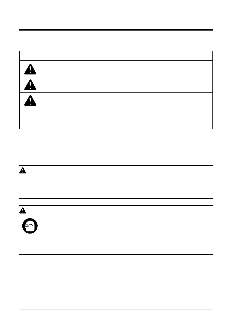
daNgER Indicates an imminently hazardous situation, which, if not
avoided, will result in death or serious injury.
WaRNINg Indicates a potentially hazardous situation, which, if not avoided,
could result in death or serious injury.
caUTION Indicates a potentially hazardous situation, which, if not avoided,
may result in minor or moderate injury.
caUTION (Without Safety Alert Symbol) Indicates a situation that may
result in property damage.
SaVE THESE INSTRUcTIONS
SYMBOL SIgNaL MEaNINg
10
ELECTRICAL
W a R N I N g
To AVoID ELECTRICAL HAZARDS, fIRE HAZARDS, oR DAMAGE To THE TooL, uSE
PRoPER CIRCuIT PRoTECTIoN. YouR EDGER IS WIRED AT THE fACToRY foR 120 V
oPERATIoN. CoNNECT To A 120V, 15A CIRCuIT AND uSE A 15A TIME-DELAYED fuSE oR
CIRCuIT BREAKER. To AVoID SHoCK oR fIRE WHEN THE PoWER CoRD IS WoRN, CuT,
oR DAMAGED IN ANY WAY, REPLACE IT IMMEDIATELY.
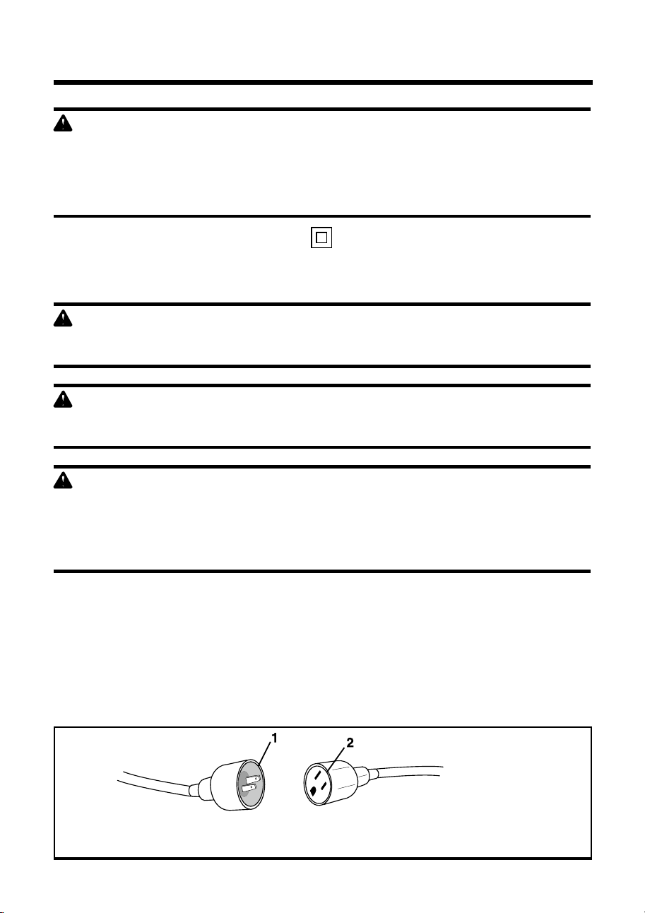
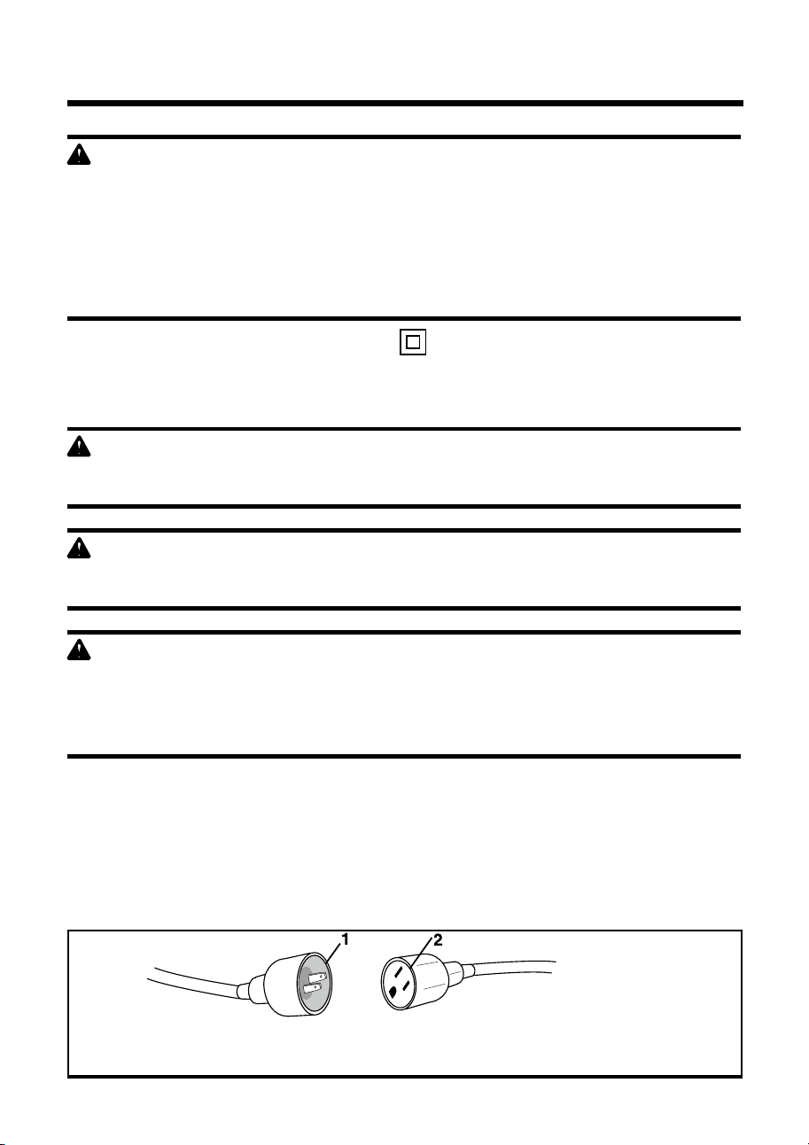
dOUBLE INSULaTEd (See Figure 1.)
This edger has a plug that looks like the one shown in fig. 1.The edger is double insulated to
provide a double thickness of insulationbetween you and the tool’s electricalsystem. Allexposed
metal parts areisolated from the internal metal motorcom-ponents with protective insulation.
W a R N I N g
To AVoID INJuRY, WHEN SERVICING THE EDGER uSE oNLY IDENTICAL REPLACEMENT
PARTS.
W a R N I N g
DouBLE INSuLATIoN DoES NoT TAKE THE PLACE of NoRMAL SAfETY PRECAuTIoNS
WHEN oPERATING THIS TooL.
W a R N I N g
To AVoID ELECTRIC SHoCK:
• use only identical replacement parts when servicing a tool with double insulation.
Servicing should be performed by a qualied technician.
• Do not use in wet or damp areas or expose to rain.
gROUNdINg INSTRUcTIONS
IN THE EVENT of A MALfuNCTIoN oR BREAKDoWN, grounding provides the path of least
resistance for electric current and reduces the risk of electric shock. This tool is equipped with
an electric cord that has a PoLARIZED plug.The power cord MuST be plugged into a matching
outlet that is properly installed and grounded in accordance with ALL local codes and ordinances.
Do NoT MoDIfY THE PLuG PRoVIDED. If it will not t the outlet, have the proper outlet
installed by a qualied electrician.
1) 2-prong plug
2) Properly grounded extension cord
fig. 1

ELECTRICAL
11
SaVE THESE INSTRUcTIONS
c a U T I O N
IN ALL CASES, MAKE CERTAIN THE RECEPTACLE IN QuESTIoN IS PRoPERLY GRouNDED.
If You ARE NoT SuRE, HAVE A CERTIfIED ELECTRICIAN CHECK THE RECEPTACLE.
W a R N I N g
THIS EDGER IS foR ouTDooR uSE oNLY. Do NoT EXPoSE To RAIN oR uSE IN DAMP
LoCATIoNS.
gUIdELINES FOR USINg EXTENSION cORdS
uSE THE PRoPER EXTENSIoN CoRD. Make sure your extension cord is in good condition.
When using an extension cord, be sure to use one of heavy enough gauge to carry the current
your product will draw. An undersized cord will cause overheating. The table below shows the
correct size to use depending on cord length and nameplate ampere rating. If in doubt, use the
next heavier gauge.The smaller the gauge number, the heavier the cord.
Make sure your extension cord is properly wired and in good electrical condition. Always replace
a damaged extension cord or have it repaired by a qualied person before using it. Keep your
extension cords away from sharp objects, excessive heat and damp or wet areas.use a separate
electrical circuit for your tools. This circuit should not be less than #12 wire and should be
protected with a 15 A time delayed fuse. Before connecting the motor to the power line, make
sure the switch is in the off position and the electric current is rated the same as the current
stamped on the motor nameplate. Running at a lower voltage will damage the motor.
W a R N I N g
ALTHouGH THIS TooL IS DouBLE INSuLATED, THE EXTENSIoN CoRD AND RECEPTACLE
MuST STILL BE GRouNDED WHILE IN uSE To PRoTECT THE oPERAToR fRoM
ELECTRICAL SHoCK.
MINIMUM gaUgE FOR EXTENSION cORdS (aWg)
(WHEN uSING 120 V oNLY)
amp Rating Total Length of cord in Feet (meters)
More Than Not More Than 25' (7.6 m) 50' (15 m) 100' (30.4 m) 150' (45.7 m)
0 6 18 16 16 14
6 10 18 16 14 12
10 12 16 16 14 12
12 16 14 12 Not Recommended

12
KNoW YouR LAWN EDGER
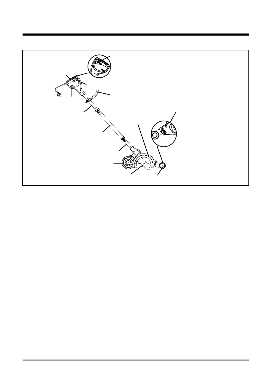
KNOW YOUR EdgER (See Figure 2.)
The safe use of this product requires an understanding of the information on the tool and in this
operator’s manual as well as a knowledge of the project you are attempting. Before use of this
product, familiarize yourself with all operating features and safety rules.
cORd RETaINER
A convenient cord retainer helps keep the extension cord connection secure during tool
operation.
FRONT HaNdLE
for ease of operation, the edger is equipped with a front handle.
LaWN EdgINg aNd TRENcHINg
The edger blade can be adjusted to depths that allow for either lawn edging or for trenching.
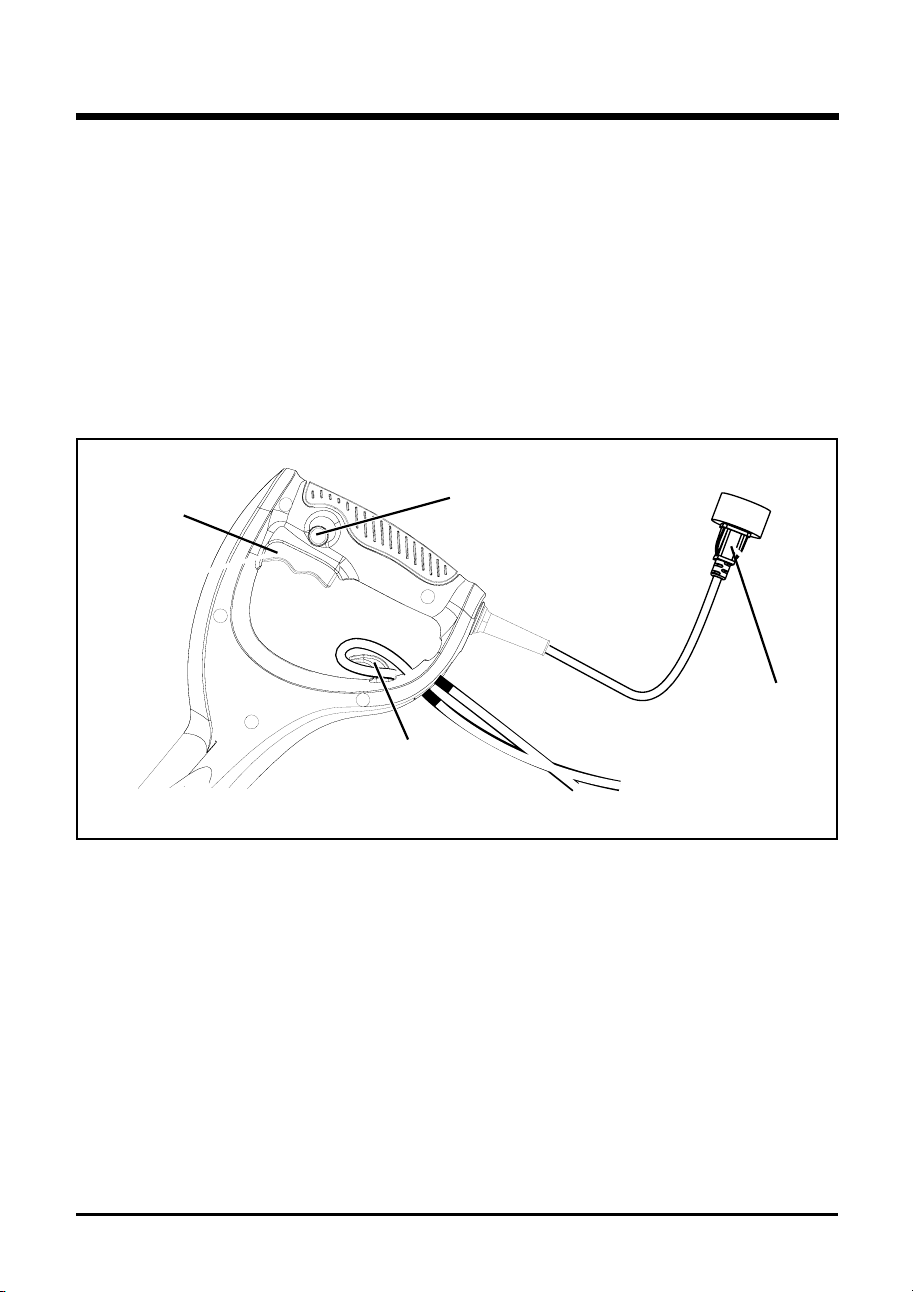
LOcK-OFF BUTTON
The lock-off button reduces the possibility of accidental starting.
SPRINg aSSIST FRONT WHEEL
The spring assist front wheel allows the user to determine the depth of the edger blade.
WHEELS
The front wheel and rear wheels are designed to t snugly on top of curbs for improved edging.
LOcK-OFF
BUTTON
REaR
HaNdLE
SWITcH
TRIggER
cORd
RETaINER
UPPER
HaNdLE TUBE
MIddLE
HaNdLE TUBE
LOWER
HaNdLE TUBE
adJUSTaBLE
FRONT HaNdLE
EdgER
gUaRd
adJUSTINg
KNOB
WHEELS
BLadE
SPRINg aSSIST
FRONT WHEEL
fig. 2

13
UNPacKINg
• This product requires assembly.
• Carefully remove the product and any accessories from the box. Make sure that all
items listed in the packing list are included.
• Inspect the product carefully to make sure no breakage or damage occurred during
shipping.
• Do not discard the packing material until you have carefully inspected and satisfactorily
operated the product.
• If any parts are damaged or missing, please call 1-888- 909-6757 for assistance.
PacKINg LIST
• Edger
• Wrench
• Operator’s Manual
ASSEMBLY
W a R N I N g
If any parts are damaged or missing, do not operate this product until the parts are replaced.
failure to heed this warning could result in serious personal injury.
W a R N I N g
Do not attempt to modify this product or create accessories not recommended for use with this
product. Any such alteration or modication is misuse and could result in a hazardous condition
leading to possible serious personal injury.
W a R N I N g
Do not connect to power supply until assembly is complete. failure to comply could result in
accidental starting and possible serious personal injury.
14
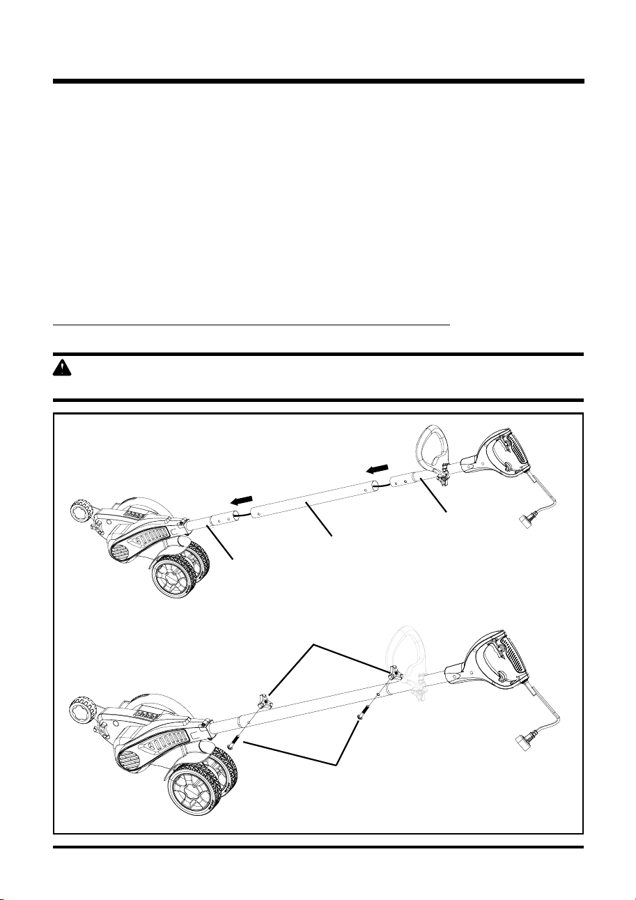
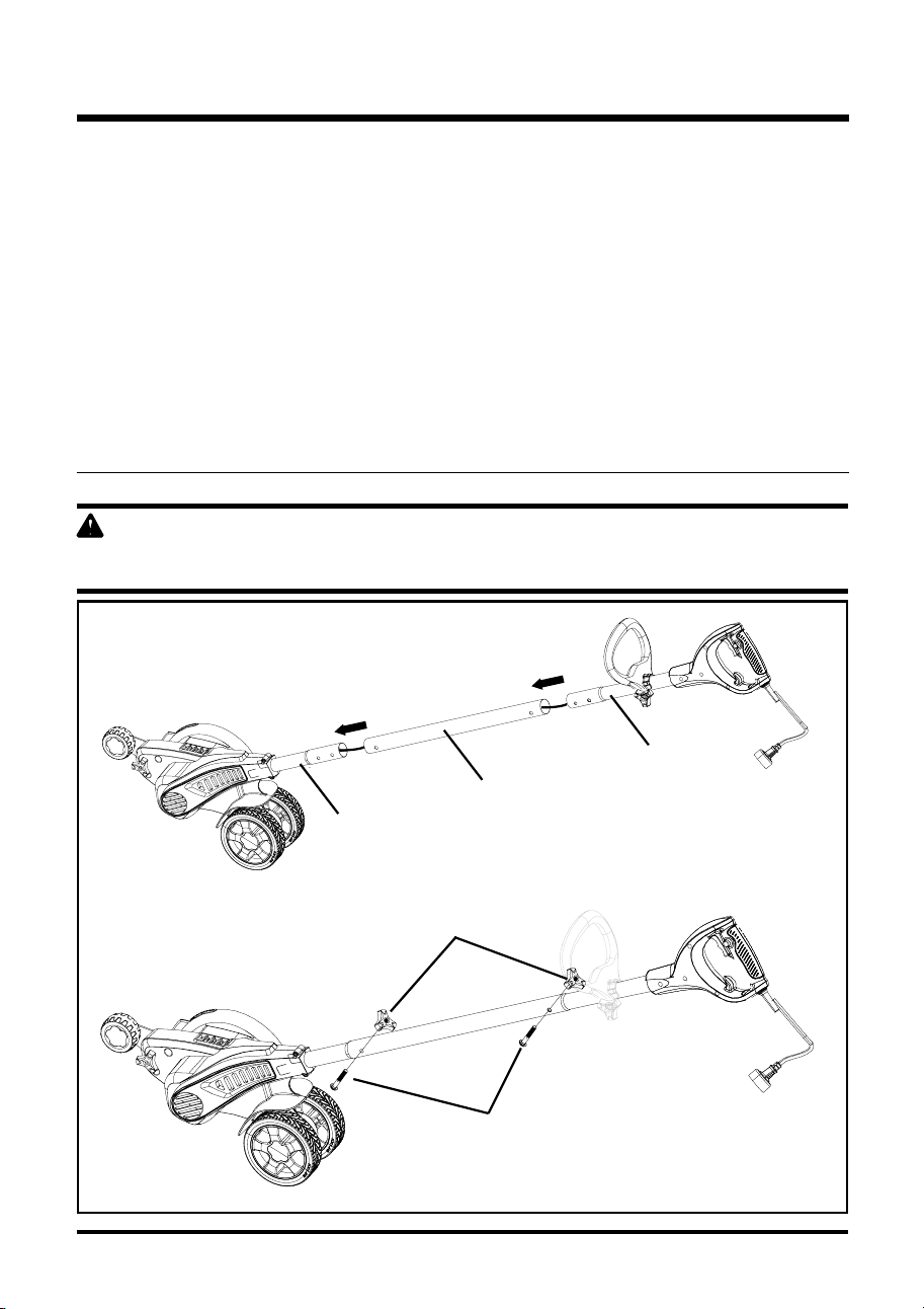
cONNEcTINg THE POLES (See Figure 3.)
Before using the edger, a one-time assembly is required. When removed from the box, the three
poles are connected by an electrical cord as shown below.
1. Remove packaging material from cord and discard.
2. Slide upper handle tube down into middle handle tube so that the holes will line up,
There are two positions available on both upper handle tube and lower handle tube for
adjustment to your preferred height setting.Ensure the power cable moves smoothly down
into the middle handle tube while assembling.
3. fasten handle tubes together with the knob (1) and curved heat bolt (2). Note that when
you rst insert the bolt it may be necessory to wiggle it carefully to get it pass the jacketed
wire inside the tube.
4. Repeat this process to attach the middle handle tube to the lower handle tube.
caUTION: NEVER use a sharp object to move jacketed wires out of the way.
W a R N I N g
failure to lock handle tubes as directed above could result in serious injury or death.
fig. 3
LOWER
HaNdLE
TUBE
MIddLE
HaNdLE
TUBE
BOLT (2)
KNOB (1)
UPPER
HaNdLE
TUBE
ASSEMBLY

15
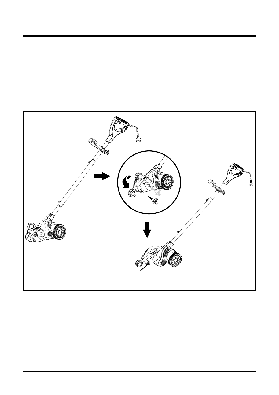
aSSEMBLINg THE FRONT WHEEL (See Figure 4.)
Before using the edger, a one-time assembly is required. When removed from the box, the front
wheel is as shown below (A).
1. Screw off the adjusting knob from the hole (1).
2. Put down the front wheel.
3. Insert the adjusting knob into the hole (2) and tighten it.
fig. 4
(a)
(B)
(c)
(1)
(2)
adJUSTINg
KNOB
ASSEMBLY

16
W a R N I N g
Do not allow familiarity with this product to make you careless. Remember that a careless fraction
of a second is sufcient to inict serious injury.
W a R N I N g
Always wear safety goggles or safety glasses with side shields when operating power tools. failure
to do so could result in objects being thrown into your eyes, resulting in possible serious injury.
W a R N I N g
Do not use any attachments or accessories not recommended by the manufacturer of this product.
The use of attachments or accessories not recommended can result in serious personal injury.
aPPLIcaTIONS
You may use this product for the purpose listed below:
• Edging around walkways, driveways, curbs, and ower beds
• Trenching
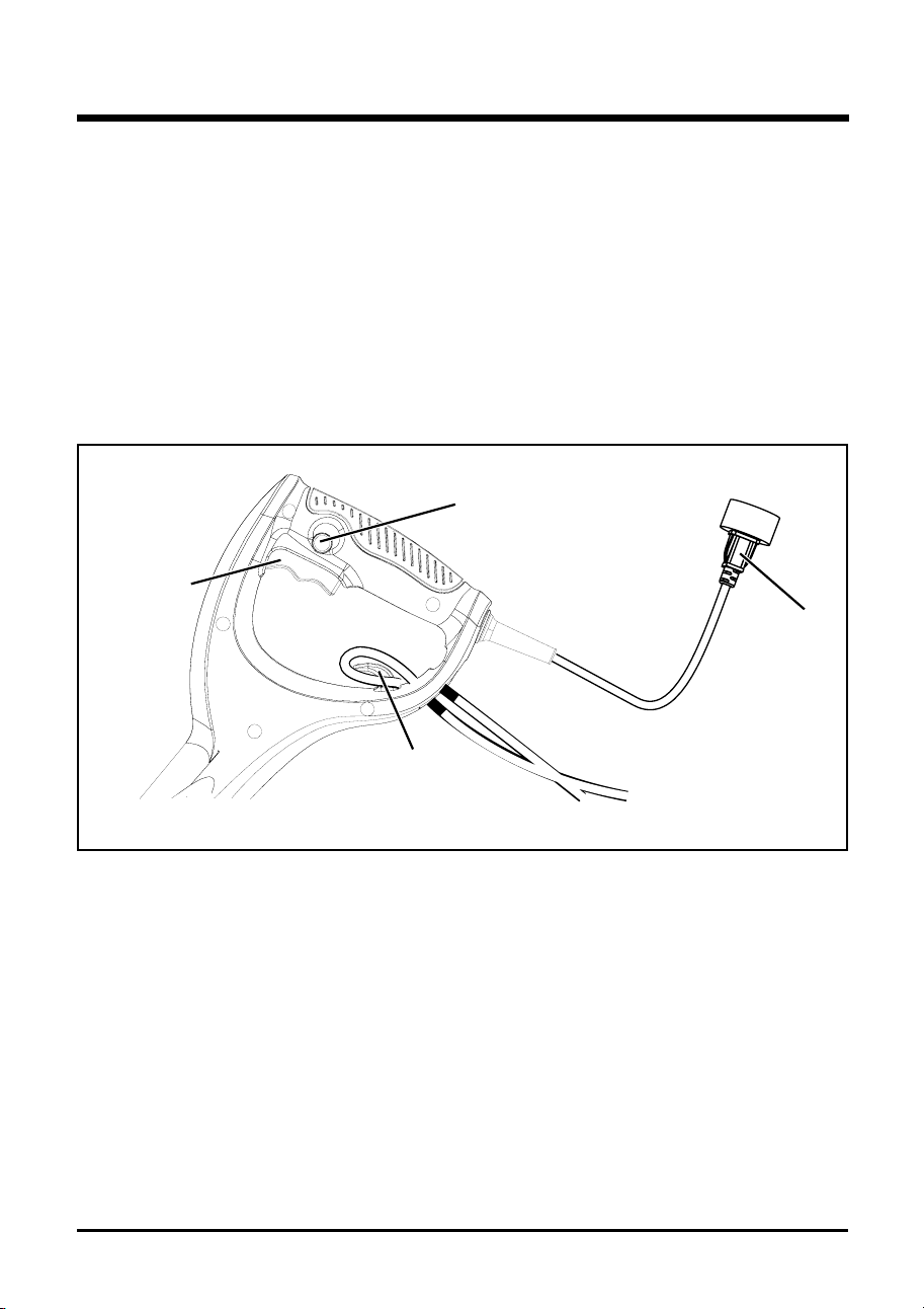
cONNEcTINg TO POWER SUPPLY (See Figure 5.)
This product is designed with a cord retainer that prevents the extension cord from being pulled
loose while using.
• form a loop with the end of the extension cord.
• Insert loop portion of extension cord through opening in the bottom of the rear handle and
place over cord retainer.
• Slowly pull loop against cord retainer until the slack is removed.
• Plug product into extension cord.
NOTE: Failure to remove all excess cord slack from extension cord retainer could result in plug loosening
from receptacle.
ASSEMBLY
17
STaRTINg aNd STOPPINg (See Figure 5.)
To start the motor:
• Plug the edger into an AC power outlet.
• Press and hold the Lock-off button and squeeze the switch trigger. The edger will stay
oN as long as the trigger switch is squeezed.
To stop the motor:
• Release the switch trigger.
• Allow at least 5 seconds for blades to stop rotating.
• The edger will be locked off until you press the Lock-off button again.
fig. 5
SWITcH
TRIggER
LOcK-OFF
BUTTON
cORd
RETaINER
OUTLET
ENd
oPERATIoN

18
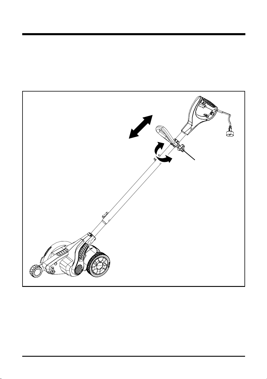
POSITION aUXILIaRY HaNdLE (See Figure 6.)
• Rotate the knob counterclockwise to loosen.
• Adjust the auxiliary handle to the desired position.
• Rotate the knob clockwise to secure.
fig. 6
UP
dOWN
KNOB
ROTaTE 360º
oPERATIoN
19
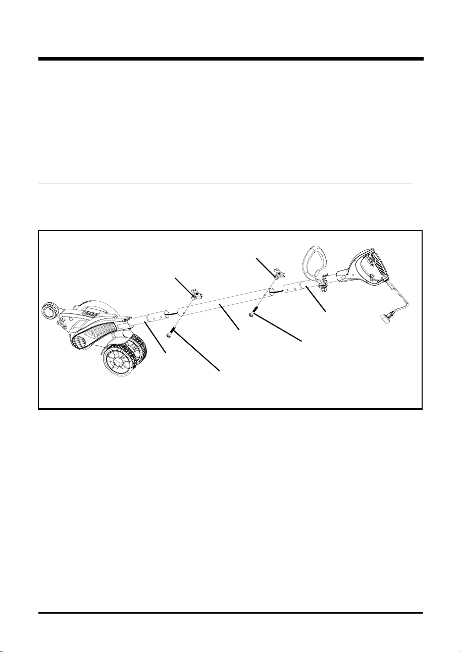
adJUSTINg POLE HEIgHT
(See Figure 7.)
• Disconnect the edger from the power supply.
• Rotate the knobs counterclockwise to loosen.
• There are two positions available on both upper handle tube and lower handle tube for
adjustment to your preferred height setting.
• fasten handle tubes together with the knob and bolt to secure.
NOTE : Adjust hand placement on the shaft of the edger to keep proper balance. Do not attempt to use the
edger at a length which does not allow you to achieve proper footing and balance at all times.
fig. 7
KNOB
KNOB
BOLT
BOLT
UPPER
HaNdLE
TUBE
MIddLE
HaNdLE
TUBE
LOWER
HaNdLE
TUBE
oPERATIoN
20
adJUSTINg dEPTH OF cUT (See Figure 8-9.)
The front wheel can be adjusted to allow a deeper or shallower cut, and to increase the life of the
blade. Change the edging depth from the shipping position to your desired depth by:
• Wait for blade to come to a complete stop.
• u NPLu G Too L.
• Loosen the adjusting knob and move the wheel up to increase the depth or down to
decrease the depth.
• After adjustment is complete, tighten the adjusting knob securely.
NOTE: Adjust the blade depth from 1/2 in. to 1 in. deep initially. Make a shallow cut to test the cutting depth.
If the cutting depth needs adjusting, this should be done progressively until the desired depth is
reached. To increase blade life span, keep initial cutting depth at minimum and increase depth setting
only as blade wears.
W a R N I N g
Thick overgrowth may drag on the guard. Reduce cut depth to minimum to help reduce this affect.
Fig. 8
Fig. 9
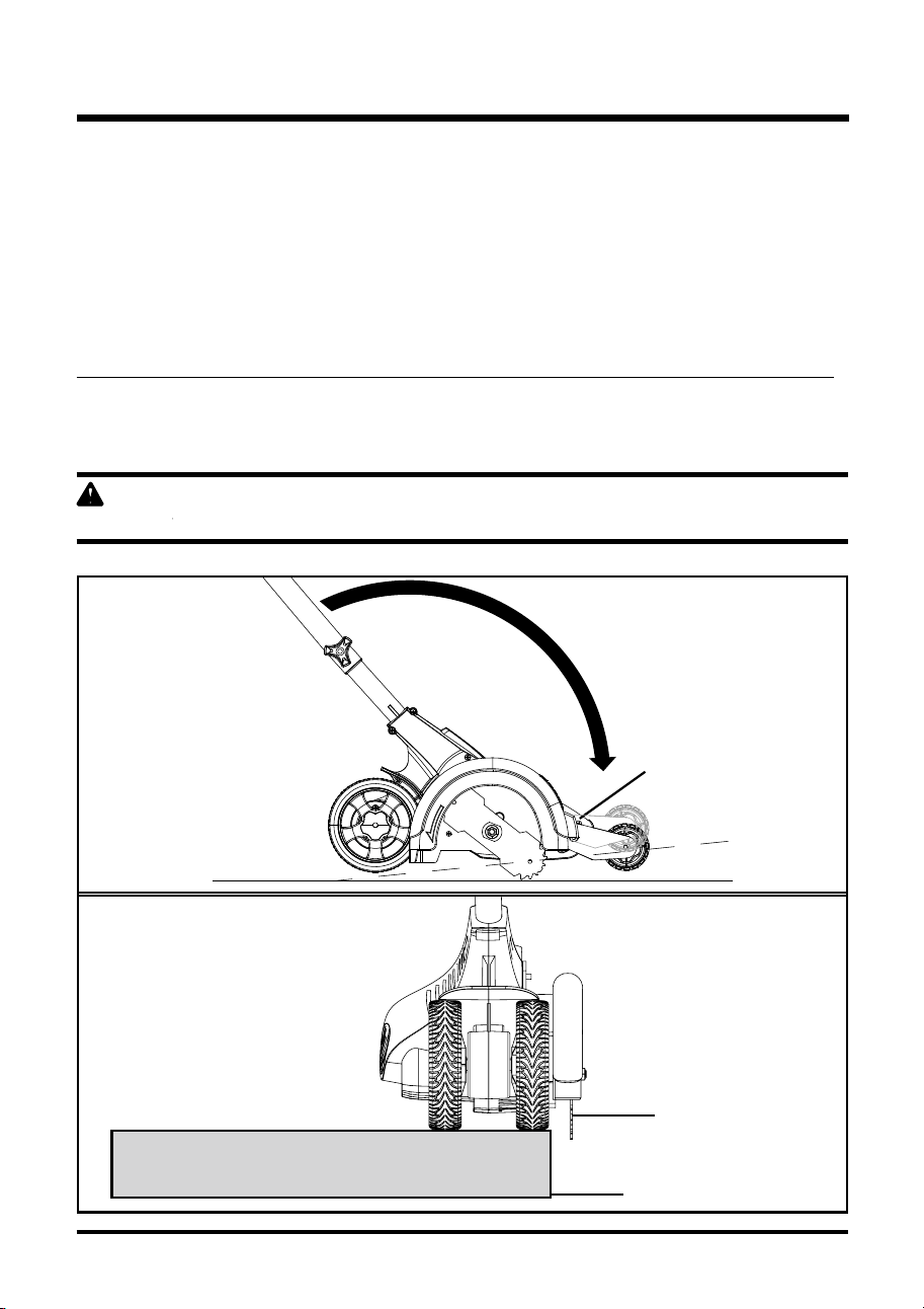
BLadE
cURB
BLadE
dEPTH
TO INcREaSE
dEPTH
TO dEcREaSE
dEPTH
adJUSTINg
KNOB
o PERATIo N

21
OPERaTINg TIPS
NOTE: The edger requires a lot of power and should not be operated simultaneously with other tools or
utilities on the same household circuit.
• Set initial cut depth at 1" and set edge guide to the down posotion.
• Before starting the edger line up the tool so the edger guide rests against the edge of the
paved surface. Both rear wheels should be on the paved surface when edging.
NOTE: When there is heavy overgrowth of grass over the paved surface it may dragon the guard. An initial
cut may be require reducing the depth at cut.
• To avoid kickback, push the handle down so the blade is above the guard.
• Turn switch oN and allow blade to spin without moving tool.
• Slowly lift the handle to lower the blade. find the edge of the paved surface and start edging.
Then move tool forward slowly along edge of paved surface, keeping the edge guide pressed
lightly against the pavement edge.
for the rst edging of each season, it is best to move forward slowly because early in the season
grass is thickest. Subsequent edging will be completed more rapidly. If the tool slows down, back
it up an inch or two until the balde comes up to normal speed. During edging some sparks may
be generated from hitting stones. This is normal. Do not attempt to edge when the grass or soil is
wet or moist for electrical safety and to prevent clogging of the blade chamber. If you must edge
under conditions that causethe blade chamber to become clogged, release trigger, wait for blade
to come to complete stop, uNPLuG TooL, open door and remove clogged meterial with a stick.
To continue to operate the tool in a clogged condition will seriously overload the motor.
c a U T I O N
Do not attempt to unclog the blade chamber by dropping or tapping the tool on the ground. This
can damage the unit. Keep hands clear of the edge guide andblade when cleaning as these wear
to a very sharp point during edging.
W a R N I N g
Make sure that other people and pets are at lease 100' away from the work area.
W a R N I N g
Before landscaping or trenching, inspect and ensure there are no exposed or buried cables, pipes
or other objects that may create a hazard or interfere with operating the edger. Set depth to only
that required for the job. Do not overload. If tool slow down, back up slightly and wait until blade
comes backup to normal speed.
oPERATIoN

22
W a R N I N g
When servicing, use only identical replacement parts. use of any other parts may create a hazard
or cause product damage.
W a R N I N g
Always wear safety goggles or safety glasses with side shields during power tool operation or when
blowing dust. If operation is dusty, also wear a dust mask.
W a R N I N g
Before inspecting, cleaning or servicing the unit, stop the motor, wait for all moving parts to stop,
and disconnect from power supply. failure to follow these instructions can result in serious personal
injury or property damage.
gENERaL MaINTENaNcE
Avoid using solvents when cleaning plastic parts. Most plastics are susceptible to damage from
various types of commercial solvents and may be damaged by their use. use clean cloths to
remove dirt, dust, oil, grease, etc.
W a R N I N g
Do not at any time let brake uids, gasoline, petroleum-based products, penetrating oils, etc., come
in contact with plastic parts. Chemicals can damage, weaken, or destroy plastic, which may result
in serious personal injury.
Stop the motor and unplug the edger whenever you leave the operating position. unplug the
edger before unclogging the blade guard or when making a repair, adjustment, inspection, etc.
Keep all nuts, bolts, and screws tight.
You can often make adjustments and repairs described here. for other repairs, have the product
serviced by an authorized service dealer.
W a R N I N g
Do not attempt to sharpen blade. failure to heed this warning could result in serious personal injury
or property damage.
MAINTENANCE
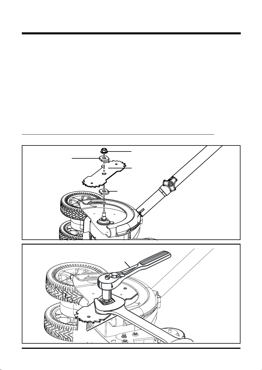
OUTER
FLaNgE
WaSHER
INNER
FLaNgE
WaSHER
BLadE NUT
BLadE
23
REPLacINg THE BLadE (See Figures 10 - 11.)
Replace blades that are damaged or worn. To increase blade life span, keep initial cutting depth
at minimum and increase depth setting only as blade wears.
• Stop the motor and unplug the edger.
• using a 26 mm wrench, hold the inner ange washer.
• using a 16 mm socket wrench, turn the blade nut coun-terclockwise to loosen.
• Remove blade nut, outer ange washer, blade, and inner ange washer.
• Reinstall the inner ange washer onto the edger shaft.
• Center the new blade on the inner ange washer, making sure the blade sits at.
• Install the outer ange washer onto the edger shaft.
• using a 26 mm wrench, hold the inner ange washer.
• Install the blade nut onto the edger shaft.
• using a 16 mm socket wrench, turn the blade nut clockwise and tighten securely.
NOTE: Always make sure the blade is correctly installed and securely fastened before each use.
fig. 10
fig. 11
16 mm
SOcKET WRENcH
26 mm
WRENcH
MAINTENANCE

24
STORINg THE EdgER
• Be sure the tool is unplugged.
• Remove and clean any debris from the outside of the edger and inside of the guard before
storage. If necessary, the edger may be stored by hanging on a hook by the handle.
• Clean all foreign material from the edger.
• Store it in a place that is inaccessible to children.
• Keep away from corrosive agents such as garden chemicals and de-icing salts.
caUTION: Do NoT HANG EDGER BY THE TRIGGER oR PoWER CoRD.
NOTE: Do not store the tool near fertilizers or chemicals. Such storage can cause rapid corrosion.
MAINTENANCE

25
Motor fails to start when 1. Power cord is not plugged 1. Plug in the power cord.
switch trigger is depressed. in or connection is loose.
2. Household circuit breaker 2. Check circuit breaker.
is tripped.
TRouBLESHooTING
PLOBLEM POSSIBLE caUSE SOLUTION

26
GREENWORKS hereby warranties this product, to the original purchaser with proof of
purchase, for a period of three (3) years against defects in materials, parts or workmanship.
GREENWORKS, at its own discretion will repair or replace any and all parts found to be
defective, through normal use, free of charge to the customer. This warranty is valid only for
units which have been used for personal use that have not been hired or rented for industrial/
commercial use, and that have been maintained in accordance with the instructions in the
owners’ manual supplied with the product from new.
ITEMS NOT COVERED BY WARRANTY:
1. Any part that has become inoperative due to misuse, commercial use, abuse, neglect,
accident, improper maintenance, or alteration; or
2. The unit, if it has not been operated and/or maintained in accordance with the owner's
manual; or
3. Normal wear, except as noted below;
4. Routine maintenance items such as lubricants, blade sharpening;
5.
GREENWORKS HELPLINE (1-888-90WORKS):
Warranty service is available by calling our toll-free helpline, 9am to 5pm EST. Monday – f riday
at 1-888-909-6757 (1-888-90WORKS).
TRANSPORTATION CHARGES:
Transportation charges for the movement of any power equipment unit or attachment are the
responsibility of the purchaser. It is the purchaser’s responsibility to pay transportation charges
for any part submitted for replacement under this warranty unless such return is requested in
writing by GREENWORKS
WARRANTY
YEAR
AÑOS
LIMITED WARRANTY
GARANTÍA
LIMITADA
3
27
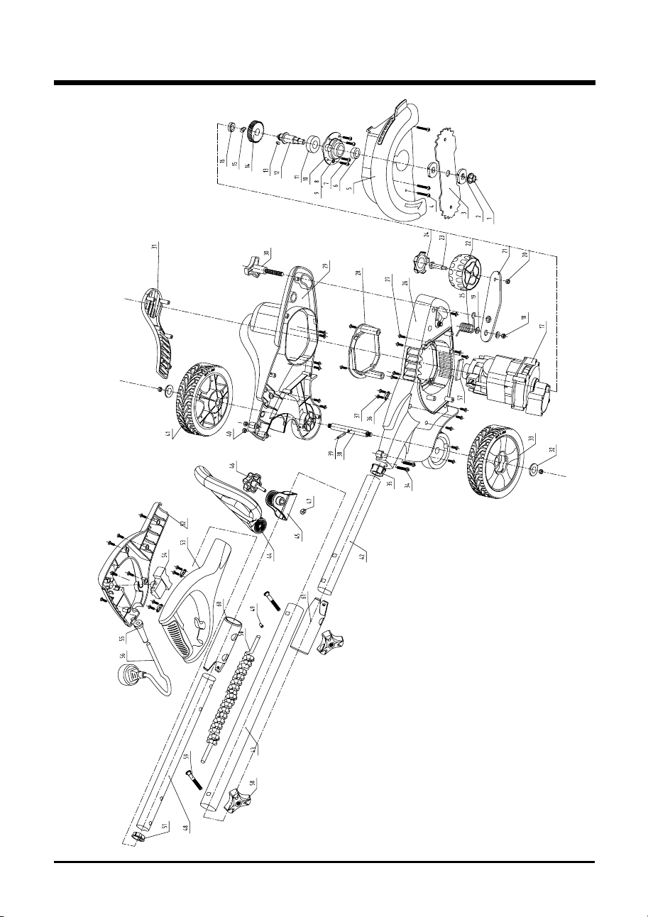
EXPLODED VIEW

28
ITEM NO. PaRT NO. dEScRIPTION QTY
1 3221037 Bolt 1
2 3330418A Board 2
3 33301261 Blade 1
4 3220351 Bolt 3
5 34103263-1 Blade cover 1
6 34908261 Seal rimg 1
7 3220811 Bolt 4
8 3290305 f lat washer 4
9 3290675 Washer 4
10 33103261 Transmission cover 1
11 32109261 Bearing 1
12 33208261 f ix shaft 1
13 32902261 f lat key 1
14 33508261 Gear wheel 1
15 3290448 Washer 1
16 32108261 Bearing 1
17 36101263-1 Motor 1
18 32208261 Nut 3
19 3220898 Washer 1
20 32907152 Nut 1
21 33303263 Adjust bar 1
22 34119263-1 3" front wheel 1
23 33203263 pillar 1
24 3411799C Wheel cover 3
25 33401263 Torsion 1
26 34102263-1 Right housing 1
27 3220505 Bolt 30
28 34105263 Guard 1
29 34101263-1 Left housing 1
30 34110263
Lock turn cap 1
31 34104263-1 o utlet cover 1
32 33304261 Washer for shaft 3
33 3411799-4 6" wheel assembly 1
34 3220552 Bolt 2
35 34113263 lower collar 1
36 3410302 Cord clip 3
37 3220905 Screw 3
38 33202263 Rear wheel shaft 1
39 32988261 Pin 1
40 32204100 Nut 1
41 3411799-3 6" left wheel assembly 1
42 33301263-1 Lower tube 1
PARTS LIST

29
ITEM NO. PaRT NO. dEScRIPTION QTY
43 33302262-1 Middle tube 1
44 3110182-6 Auxiliary handle assembly 1
45 34101266 Lock tube for auxiliary handle 1
46 3110282-6 Turn cap for auxiliary handle 1
47 3290205 Nut 1
48 33301262-1 u pper tube 1
49 36511154 Connector cap 2
50 36901263 Wire 1
51 34115263 u pper collar 4
52 34106263-1 Left handle 1
53 34107263-1 Right handle 1
54 36301263-1 Switch 1
55 3420102-1 Retainer 1
56 36401263 Power cord 1
57
58
59
60
61
34901263
3410835-6
3220436
34120263
34120263
Sponge
Turn cap
Bolt for handle
Inner tube
Inner tube
1
2
2
1
1
PARTS LIST

NoTES

NoTES

TOLL-FREE HELPLINE: 1-888-90WORKS
(888.909.6757)
Greenworks Tools
P.O. Box 1238
Mooresville, NC 28115

Antes de hacer funcionar esta herramienta, lea cuidadosamente todas las reglas
de seguridad y las instrucciones.ng this tool.
Manual del Propietario
LÍNEA TELEFÓNICA GRATIS PARA AYUDA: 1-888-90WORKS
(888.909.6757)
REBORDEADOR DE CÉSPED
ELÉCTRICO
DE 19 CENTÍMETROS (7-1/2 PULGADAS)
27032
www.greenworkstools.com

2
Índice ................................................................................................................................... 2
............................................................................................. 2
Instrucciones importantes sobre seguridad ......................................................................3 -5
......................................................................................... 6
Símbolos .........................................................................................................................9-10
Sistema eléctrico .......................................................................................................... 11-12
Familiarícese con césped....................................................................................................13
Ensamblaje ................................................................................................................... 14-17
Funcionamiento .............................................................................................................18-22
Mantenimiento .............................................................................................................. 23-25
Troubleshooting ................................................................................................................. 26
Garantía ............................................................................................................................. 2 7
Diagrama de componentes ........................................................................................... 28-30
ESPECIFICACIONES DEL PRODUCTO
REBORDEADOR DE CÉSPED ELÉCTRICO DE 19 CENTÍMETROS (7-1/2
PULGADAS) ......................................................................................................................
Alimentación ................................................. 120 V, CA solamente, 60 Hz, 12 Amperios
Longitud de la cuchilla ......................................................................... 19cm (7-1/2 pulg.)
Peso ...................................................................................................... 6,3 kg (14 Lbs.))
ÍNDICE
YEAR
AÑOS
LIMITED WARRANTY
GARANTÍA
LIMITADA
3

3
I NS T R U C C I O N E S I M P O R TA N T ES S O B R E
SEGURIDAD
A D V E R T E N C I A
Lea y comprenda todas las instrucciones. No obedecer todas las instrucciones que se listan a
continuación podría resultar en choques eléctricos, incendios o lesiones personales graves.
• Lea cuidadosamente el manual del operador. Familiarícese completamente con los controles
y el uso apropiado del equipo. Aprenda cómo parar la unidad y desconectar los controles
rápidamente.
• No permita que niños ni personas sin capacitación usen esta unidad.
• Cada vez antes de usar la herramienta, limpie el área de trabajo. Quite todo objeto
inadecuado tal como rocas, fragmentos de vidrio, clavos, alambre o cuerdas que pudieran
saltar o enrollarse en la cuchilla del rebordeador.
• Al operar este producto, use anteojos o gafas de seguridad con viñetas que indiquen que
cumplen el estándar ANSI Z87.1.
• Vístase apropiadamente; no use ropa o joyería holgadas. Se podrían atorar en las piezas
móviles.
• Se recomienda usar guantes resistentes. Al trabajar a la intemperie se recomienda usar
guantes de caucho y calzado resistente. Use una cubierta protectora para contener el cabello
largo.
• No use el producto al estar descalzo o usando sandalias. Use siempre calzado de seguridad
y pantalones o calzones que cubran las piernas.
• Nunca haga funcionar esta unidad por el lado izquierdo del operador.
• Mantenga a los niños, espectadores y mascotas alejados por lo menos 15 metros (50 pies).
Se debe pedir a los espectadores usar protección para los ojos. Si alguien se le acerca,
detenga el motor y los accesorios.
• Manténgase alerta, ponga atención a lo que está haciendo y use el sentido común. No opere
este producto cuando esté cansado o bajo la inuencia de drogas, alcohol o medicamentos.
• No lo opere en lugares con poca iluminación.
• Asiente rmemente los pies y mantenga el equilibrio. No extienda su cuerpo más allá de
su alcance natural. Hacerlo podría resultar en la pérdida del equilibrio o en exposición
a supercies calientes. Mantenga los accesorios para cortar por debajo de su cintura.
Mantenga todas las partes de su cuerpo alejadas de las piezas móviles.
PELIGRO: CUCHILLA ROTATORIA
• Mantenga ambas manos sobre las manijas cuando la cuchilla esté girando.
• Mantenga las manos y los pies alejados del área de corte.
• Cuando el motor esté funcionando o cuando la cuchilla esté en movimiento no intente
desplazar el material recientemente cortado ni de sostener el material que desee cortar.
•
Asegúrese de que la unidad esté desenchufada al desalojar material atascado en la
cuchilla.

4
I N S T R U C C I O N ES I M P O RTA N T E S S O B R E
SEGURIDAD
• Mantenga las cubiertas protectoras en su lugar.
• Mantenga la cuchilla limpia y alada. Reemplace la cuchilla cuando sea necesario.
•PRECAUCIÓN: LA CUCHILLA CONTINÚA MOVIÉNDOSE LUEGO DEL APAGADO.
• Desenchufe la herramienta antes de efectuar cualquier ajuste o reparación. Use equipo para
protección y obedezca todas las instrucciones de seguridad. Al apagar la unidad, asegúrese
de que la cuchilla se ha detenido antes de asentar la unidad.
• Inspeccione la unidad antes de cada uso para asegurarse que no tiene tornillos o sujetadores
ojos. Antes de usarla reemplace las piezas dañadas.
• Bajo ninguna circunstancia, utilice con este producto accesorios o agregados que no hayan
sido enviados en conjunto con él o que en el manual del operador no se haya especicado
que son apropiados para ser utilizados con este producto.
• Evite los entornos peligrosos. No use el producto en lugares húmedos o mojados.
• No lo use bajo la lluvia.
• Si el equipo vibra anormalmente, detenga el motor inmediatamente y revíselo para averiguar
la causa.
• La vibración generalmente indica la existencia de problemas.
• Antes de hacer reparaciones, inspecciones o limpieza, apague el motor y asegúrese
de que todas las piezas móviles se han detenido. Solamente personal calicado para
hacer reparaciones debe darle servicio al producto. Las reparaciones o el mantenimiento
efectuados por personal no calicado podrían resultar en lesiones al usuario o daños al
producto.
• Use solamente repuestos idénticos al darle servicio al producto. El uso de piezas no
autorizadas puede provocar lesiones graves al usuario o dañar el producto.
• Para reducir el riesgo de choques eléctricos, esta herramienta cuenta con un enchufe
polarizado (una de sus aspas es más ancha que la otra) y es necesario utilizar un cordón para
extensión polarizado. El enchufe se acopla solamente de una forma en los cordones para
extensión polarizados. Si el enchufe no se acopla exactamente al cordón para extensión,
invierta el modo de conexión. Si el enchufe aún no se acopla, busque un cordón para
extensión polarizado adecuado. Para conectar un cordón para extensión polarizado se debe
utilizar un tomacorriente polarizado. Esos enchufes se acoplan solamente de una forma en
los tomacorrientes polarizados. Si el enchufe no se acopla completamente al tomacorriente,
invierta el modo de conexión. Si el enchufe aún no se acopla, póngase en contacto con un
electricista calicado para instalar un tomacorriente apropiado en la pared. No altere de
ninguna forma el enchufe del equipo, los tomacorrientes o los enchufes de los cordones para
extensión.
• Evite que su cuerpo entre en contacto con las supercies conectadas a tierra tales como
tuberías, radiadores, cocinas y refrigeradoras.
• Si su cuerpo está conectado a tierra existe un mayor riesgo de choques eléctricos.
•
No exponga el producto a la lluvia ni a las condiciones húmedas. El agua dentro de las
herramientas eléctricas aumenta el riesgo de choques eléctricos.

5
I N S T R U C C I O N ES I M P O RTA N T E S S O B R E
SEGURIDAD
• No toque el enchufe ni la herramienta con las manos mojadas.
• Al operar una herramienta eléctrica al aire libre, use un cordón de extensión para exteriores
marcado “W-A” o “W”. Esos cordones están clasicados para uso al aire libre y reducen el
riesgo de choques eléctricos. Al no estar en uso, se debe almacenar el rebordeador inactivo
en el interior, en un lugar seco, por lo alto o bajo llave fuera del alcance de los niños.
• Antes de desenchufar, apague todos los controles.
• No use la herramienta si el interruptor no la enciende o apaga. Cualquier herramienta que no
pueda ser controlada con su interruptor es peligrosa y se le debe reparar.
• No la use con el enchufe dañado. Si la herramienta no está funcionando como debiera o si se
ha caído, dañado, se le ha dejado a la intemperie o se ha caído al agua, regrésela a un centro
de servicio autorizado.
• No se aleje de la herramienta cuando esté enchufada. Desenchufe la herramienta del
tomacorriente cuando no la esté usando, antes de darle servicio, cambiar accesorios o
de almacenarla. Estas medidas preventivas de seguridad reducen el riesgo de arrancar la
herramienta accidentalmente.
• No abuse del cordón; no tire de la herramienta ni la transporte mediante su cordón, no use
el cordón como manija, no lo comprima al cerrar las puertas, ni tire de él al pasar por bordes
o esquinas puntiagudas, ni tire de él para desenchufar la herramienta. No pase el aparato
sobre su cordón. Mantenga el cordón alejado de las supercies calientes.
• No la desenchufe tirando del cordón. Para desenchufar, agarre el enchufe, no el cordón.
• No toque el enchufe ni el aparato con las manos mojadas.
• En los aparatos con aislamiento doble, se suministran dos sistemas de aislamiento en lugar
de conexión a tierra. En los aparatos con aislamiento doble no se suministran medios para
conexión a tierra ni es necesario añadirlos. Se necesita un cuidado y conocimiento extremos
del sistema para dar servicio a un aparato con aislamiento doble y debe ser efectuado
solamente por personal de servicio calicado. Los repuestos para aparatos con aislamiento
doble deben ser idénticos a las piezas originales.
• Para uso en el hogar solamente.
• Los circuitos y enchufes eléctricos en los que se ha de conectar el rebordeador deben contar
con protección GFCI o sea Interrupción de Circuito con Falla a Tierra. Hay disponibles
tomacorrientes con protección GFCI incorporada y se les puede usar como una medida extra
de seguridad.
• Evite los arranques accidentales; no transporte el rebordeador enchufado con los dedos en
el interruptor. Antes de enchufarlo asegúrese de que el interruptor esté en la posición de
apagado.
• Al levantar o sostener el rebordeador no lo tome por las cuchillas expuestas ni por los bordes
de corte.
• No presione el rebordeador, hará un mejor trabajo y con menos probabilidad de lesiones a la
velocidad para la cual fue diseñado. Dé mantenimiento cuidadoso al rebordeador; mantenga
limpios los bordes de corte con lo para obtener un mejor rendimiento y reducir los riesgos
de lesiones. Siga las instrucciones para la lubricación y el cambio de accesorios. Revise con
regularidad el cordón del rebordeador, y si está dañado, haga que lo repare una compañía
de servicio autorizada. Revise los cordones de extensión con regularidad y reemplácelos si
están dañados. Mantenga las manijas secas, limpias y libres de aceite y grasa.

• Compruebe que no hay piezas dañadas; antes de continuar usando el rebordeador, se debe
revisar cuidadosamente las cubiertas protectoras y otras piezas que se hayan dañado,
para establecer si han de funcionar apropiadamente y efectuar la función para la que se
les diseñó. Compruebe que las piezas móviles están alineadas y que no se traban, que no
hay piezas quebradas, montaje y que no hay alguna otra condición que pudiera afectar el
funcionamiento de la herramienta. A menos que se indique algo diferente en este manual,
centros de servicio autorizados deben reparar o reemplazar las cubiertas protectoras u otras
piezas dañadas.
• Use las herramientas apropiadas; no use el rebordeador para cualquier otro trabajo que no
sea para el que se le diseñó.
• Cordón para extensión: asegúrese de que su cordón para extensión se encuentre en buenas
grueso como para transmitir la corriente que necesita el producto. Para cordones de
extensión de 15 metros (50 pies) o menos de longitud se recomienda usar cordones con
calibre de alambre (AWG) 14 por lo menos. Si no esta seguro, use el siguiente calibre más
grueso. Entre menor el número del calibre, más grueso es el cordón. Los cordones de menor
calibre provocan una caída en el voltaje, lo que resulta en una pérdida de energía y en
sobrecalentamiento.
I N S T R U C C I O N E S IM P O R TA N T ES SO B R E
SEGURIDAD
6

7
REGLAS ESPECÍFICAS DE SEGURIDAD
• Asegúrese de que todas las cubiertas protectoras estén colocadas apropiadamente y con
seguridad.
• Remplace las cuchillas sin lo o desgastadas; no trate de alarlas.
• No intente alar las cuchillas. No hacer caso a esta advertencia podría provocar vibración
excesiva y lesiones personales graves o daños a la propiedad.
• Use este rebordeador para rebordear a lo largo de aceras, entradas y montículos de
jardinería. No lo use para cualquier otro propósito.
• No use el rebordeador en supercies con grava ni cerca de tales supercies.
• Si el rebordeador golpea algún objeto extraño:
• Pare el rebordeador y desconéctelo de la fuente de alimentación.
• Compruebe que los accesorios del rebordeador no se han dañado.
• Repare los daños antes de usar el accesorio del rebordeador. No hacerlo podría provocar
lesiones graves.
• Familiarícese con el área en que está trabajando. Tome nota de aceras disparejas y de
agujeros en el terreno así como otras condiciones peligrosas similares (por ejemplo: alambres
o cables que se pudieran romper y convertir en proyectiles peligrosos). Empuje lentamente el
rebordeador al encontrarse en terreno escabroso.
• Nunca descargue directamente el material hacia los espectadores ni permita la presencia
de personas cerca del área de trabajo. Tenga cuidado al dirigir la descarga de material para
evitar lanzarlo hacia supercies de vidrio, automóviles o elementos similares.
• Pare siempre el motor y desconecte la herramienta de la fuente de alimentación antes
de intentar quitar cualquier obstrucción atorada en la cuchilla así como antes de instalar
accesorios y de efectuar cualquier ajuste.
• Para reducir el riesgo de incendios, no deje que se acumule en el producto una cantidad
excesiva de hierba, hojas o grasa.
• Cuando el motor esté funcionando o cuando la cuchilla esté en movimiento no intente
desplazar el material recientemente cortado ni sostener el material que desee cortar.
• Siempre que la cuchilla esté girando mantenga su mano derecha en la manija posterior y la
izquierda en la manija frontal.
• Esté siempre atento a la ubicación del cordón eléctrico y aléjelo del área en que esté
trabajando. Los cordones podrían convertirse en peligro de tropezones para el operador. Los
cordones que se encuentran en el camino de corte podrían ser mutilados por el rebordeador.
• Nunca se pare en línea con el paso de la cuchilla del rebordeador, ni coloque así alguna parte
de su cuerpo.
• Las cuchillas en movimiento por inercia pueden provocar lesiones ya que continúan girando
luego de que se ha parado el motor o se ha soltado el gatillo de aceleración. Controle
apropiadamente la herramienta hasta que la cuchilla deje de girar completamente.
•
No deje sin atención el producto.
• Para evitar riesgos, si el cordón de alimentación se ha dañado, sólo el fabricante o un centro
de servicio autorizado pueden reemplazarlo.
GUARDE ESTAS INSTRUCCIONES

8
REGLAS ESPECÍFICAS DE SEGURIDAD
• Guarde estas instrucciones. Léalas frecuentemente y utilícelas para instruir a otros que
pudieran hacer uso de esta herramienta. Si presta esta herramienta eléctrica, preste también
estas instrucciones para evitar el mal uso del producto y posibles lesiones.
• El polvo creado por la arena a chorro, el aserrado, esmerilado, taladrado y otras actividades
de la construcción podría contener productos químicos que de acuerdo al Estado de
California provocan cáncer, defectos de nacimiento y otras
lesiones reproductivas. Algunos
ejemplos de estos productos químicos son:
• • Plomo en pintura a base de plomo
• • Sílice cristalino en ladrillos, cemento y otros productos de mampostería, y
• • Arsénico y cromo de madera con tratamiento químico.
• Su riesgo de exposición a estos productos químicos depende de la frecuencia en que efectúe
este tipo de trabajo. Para reducir su exposición a estos productos químicos, trabaje en áreas
bien ventiladas y use equipo de seguridad aprobado, tal como máscaras contra el polvo
Si el operador no se percata de la presencia de niños, se pueden generar accidentes
trágicos.
• Mantenga a los niños alejados del área de trabajo y bajo el cuidado atento de un adulto
responsable.
• No deje que niños menores de 14 años operen este rebordeador. Los niños de 14 años o
más deben leer y comprender las instrucciones de funcionamiento y las reglas de seguridad
de este manual y uno de sus padres les debe capacitar y supervisar.
• Manténgase alerta, y apague el rebordeador si un niño o cualquier otra persona ingresa al
área de trabajo.
• Antes y al moverse hacia atrás, mire hacia atrás y hacia abajo para asegurarse de que no
hay niños pequeños.
Tenga extremo cuidado al acercarse a esquinas ciegas, entradas, arbustos, árboles u otros
objetos que le pudieran obstruir la visión de niños, los cuales pudieran correr hacia el área de
trabajo del rebordeador.
ADVERTENCIA (PROPOSICIÓN 65)
SEGURIDAD DE NIÑOS

9
SÍMBOLO
NOMBRE DESIGNACIÓN/EXPLICACIÓN
V Voltios Voltaje
A Amperios Corriente
Hz Hertz Frecuencia (ciclos por segundo)
W Vatios Potencia eléctrica
min Minutos Tiempo
Corriente directa Tipo de corriente
Corriente directa Tipo o característica de la corriente
Fabricación Clase II Fabricación con aislamiento doble
Alerta de condiciones húmedas
No la exponga a la lluvia ni la use en lugares
húmedos o mojados
Lea el manual del operador
Para reducir el riesgo de lesiones el usuario
debe leer y comprender el manual del operador
antes de usar el producto
Alerta de seguridad Precauciones que involucran su seguridad.
Mantenga alejados a los
espectadores
Mantenga a todos los espectadores a 15 m.
(50 pies) de distancia.
Protección para los ojos
Al operar este producto use siempre gafas de
seguridad o gafas de seguridad con
protecciones laterales y, si es necesario,
una careta completa.
Cabello largo
Si no se mantiene alejado el cabello largo de la
entrada de aire se podrían provocar lesiones
personales.
Ropa suelta
Si no se evita que la ropa suelta sea
succionada hacia la entrada de aire se podrían
provocar lesiones personales.
Peligro por rebote
Los objetos lanzados podrían rebotar y
provocar lesiones personales o daños a la
propiedad.
Cuchillas con filo
Peligro, mantenga las manos y los pies alejados
de las cuchillas.
Fuera manos No mantener las manos alejadas de las
cuchillas resulta en lesiones personales graves.
Este producto podría contener algunos de los siguientes símbolos. Sírvase estudiarlos y aprender su
significado. La comprensión apropiada de esos símbolos le permitirá operar mejor el producto y de
una forma más segura.
SÍMBOLOS
10
SÍMBOLOS
Los siguientes rótulos y significados se usan para explicar el nivel de riesgo relacionado con este
producto.
Para dar servicio es necesario tener extremo cuidado y conocimiento, el servicio debe ser
proporcionado solamente por técnicos de servicio calificados. Sugerimos que para dar servicio al
producto lo regrese a su CENTRO DE SERVICIO AUTORIZADO más cercano para que lo reparen.
Al dar servicio, use solamente repuestos idénticos.
Para evitar lesiones personales graves, no trate de usar este producto antes de haber leído
completamente el manual del operador y haberlo comprendido en su totalidad. Si no comprende
las advertencias y las instrucciones que aparecen en el manual del operador, no use el producto.
Llame al departamento de servicio al cliente de GREENWORKS para recibir ayuda. .
SERVICIO
A D V E R T E N C I A
A D V E R T E N C I A
Toda herramienta eléctrica al funcionar puede lanzar objetos extraños hacia sus ojos,
lo que podría provocarles lesiones graves. Antes de comenzar el funcionamiento de
una herramienta eléctrica, use siempre gafas de seguridad o gafas de seguridad con
protecciones laterales y, cuando sea necesario, una careta completa. Recomendamos
usar caretas de seguridad con rango visual ancho encima de anteojos normales, o usar
gafas de seguridad estándar con protecciones laterales. Use siempre protección para
los ojos con viñetas que indiquen que cumple ANSI Z87.1.
PELIGRO Indica situaciones inminentemente peligrosas que, si no se evitan,
resultan en la muerte o en lesiones serias.
ADVERTENCIA
PRECAUCIÓN
PRECAUCIÓN (Sin el símbolo de alerta por seguridad) indica una situación que
podría resultar en daños a la propiedad.
Indica situaciones potencialmente peligrosas que, si no se evitan,
podrían resultar en lesiones entre mínimas y moderadas.
Indica situaciones potencialmente peligrosas que, si no se evitan,
podrían resultar en la muerte o en lesiones serias
GUARDE ESTAS INSTRUCCIONES
SÍMBOLO AVISO SIGNIFICADO
11
SISTEMA ELÉCTRICO
A D V E R T E N C I A
PROTEJA LOS CIRCUITOS ADECUADAMENTE PARA EVITAR LOS PELIGROS CON LA
ELECTRICIDAD, LOS INCENDIOS ASÍ COMO DAÑOS A LA HERRAMIENTA. EL REBORDEADOR
HA SIDO ENSAMBLADO DE FÁBRICA PARA FUNCIONAR CON 120 VOLTIOS. CONÉCTELO A
UN CIRCUITO DE 120V VOLTIOS, 15 AMPERIOS y USE UN FUSIBLE O CORTACIRCUITOS DE
15 AMPERIOS CON RETRAZO DE TIEMPO. PARA EVITAR CHOQUES O INCENDIOS, CUANDO
EL CORDÓN DE ALIMENTACIÓN SE HAyA DESGASTADO, CORTADO O DAÑADO DE
CUALQUIER FORMA REEMPLÁCELO INMEDIATAMENTE.
AISLAMIENTO DOBLE (vea la figura 1.)
Este rebordeador cuenta con un enchufe que luce como se muestra en la Fig. 1. El rebordeador
cuenta con aislamiento doble para suministrar una cantidad doble de aislamiento entre usted y el
sistema eléctrico de la herramienta. Todas las piezas metálicas expuestas se encuentran aisladas
de los componentes internos de metal del motor mediante aislamiento protector.
A D V E R T E N C I A
PARA EVITAR LESIONES, USE SOLAMENTE REPUESTOS IDÉNTICOS AL REPARAR EL
REBORDEADOR.
A D V E R T E N C I A
AL OPERAR ESTA HERRAMIENTA NO SE DEBEN ABANDONAR LAS PRECAUCIONES DE
SEGURIDAD NORMALES SIMPLEMENTE PORQUE CUENTA CON AISLAMIENTO DOBLE.
NO MODIFIQUE EL ENCHUFE SUMINISTRADO. Si no encaja en el tomacorriente, haga que un
electricista calificado instale uno apropiado.
A D V E R T E N C I A
PARA EVITAR CHOQUES ELÉCTRICOS:
INSTRUCCIONES PARA CONEXIÓN A TIERRA
• Use solamente repuestos idénticos al reparar herramientas con aislamiento doble.
Las reparaciones las debe efectuar un técnico calificado.
• No la use en áreas húmedas o mojadas ni la exponga a la lluvia.
EN CASO de un MAL FUNCIONAMIENTO o AVERÍA, la conexión a tierra suministra el paso de
menor resistencia para la corriente eléctrica, lo que reduce el riesgo de choques eléctricos. Esta
herramienta está equipada con un cordón eléctrico que tiene un enchufe POLARIZADO. Se DEBE
conectar el cordón de alimentación a un tomacorriente correspondiente que se encuentre
apropiadamente instalado y conectado a tierra de acuerdo con TODOS los códigos y decretos locales.
1) Enchufe de dos clavijas
2) Cordón de extensión apropiadamente conectado a tierra
Fig. 1

SISTEMA ELÉCTRICO
12
GUARDE ESTAS INSTRUCCIONES
P R E C A U C I Ó N
EN TODO CASO, ASEGÚRESE DE QUE EL TOMACORRIENTE EN CUESTIÓN SE ENCUENTRE
CONECTADO A TIERRA ADECUADAMENTE. SI NO ESTÁ SEGURO, HAGA QUE UN
ELECTRICISTA CERTIFICADO REVISE EL TOMACORRIENTE.
W A R N I N G
ESTE REBORDEADOR ES PARA USO EXTERIOR SOLAMENTE. NO LO EXPONGA A LA
LLUVIA NI LO USE EN LUGARES HÚMEDOS O MOJADOS.
PAUTAS PARA EL USO DE CORDONES PARA EXTENSIÓN
USE EL CORDÓN PARA EXTENSIÓN APROPIADO. Asegúrese de que su cordón para extensión
se encuentra en buenas condiciones. Al utilizar un cordón para extensión, asegúrese de usar uno
de calibre suficientemente grueso como para transmitir la corriente que necesita el producto. Los
cordones muy pequeños provocan sobrecalentamiento. En el cuadro a continuación se muestra el
tamaño correcto a usar dependiendo de la longitud del cordón y la clasificación de amperaje que
aparece en la placa con nombre. Si no está seguro, use el siguiente calibre más grueso. Entre
menor el número del calibre, más grueso es el cordón.
Asegúrese de que su cordón para extensión se encuentre apropiadamente conectado y en buenas
condiciones eléctricas. Antes de usarlos, reemplace siempre los cordones para extensión dañados
o haga que los repare una persona calificada. Mantenga sus cordones para extensión alejados de
los objetos puntiagudos, el calor excesivo y las áreas húmedas o mojadas. Use un circuito eléctrico
separado para sus herramientas. El circuito debe tener por lo menos alambres #12 y estar protegido
por fusibles de 15 A con retrazo de tiempo. Antes de conectar el motor al circuito eléctrico,
asegúrese de que el interruptor se encuentra en la posición de APAGADO y que la corriente
eléctrica está clasificada como la que aparece en la placa con nombre del motor. El funcionamiento
con un voltaje menor daña el motor.
A D V E R T E N C I A
PARA PROTEGER AL OPERADOR CONTRA CHOQUES ELÉCTRICOS A PESAR DE QUE ESTA
HERRAMIENTA TIENE AISLAMIENTO DOBLE, EL CORDÓN PARA EXTENSIÓN y EL
TOMACORRIENTES DEBEN AÚN ESTAR CONECTADOS A TIERRA MIENTRAS SE USA LA
HERRAMIENTA.
CALIBRE (AWG) MÍNIMO DE LOS CORDONES PARA EXTENSIÓN
(AL USAR 120 V SOLAMENTE)
Amperaje
Longitud total del cordón en metros (pies en paréntesis)
Más de No más de 7,6 m (25 pies) 15 m (50 pies) 30,4 m (100 pies) 45,7 m (150 pies)
0 6 18 16 16 14
6 10 18 16 14 12
10 12 16 16 14 12
12 16 14 12 No se recomienda
13
KNOW yOUR LAWN EDGER
FAMILIARÍCESE CON SU REBORDEADOR (Vea la figura 2.)
Para usar con seguridad este producto es necesario comprender la información que se presenta
en la herramienta y en el presente manual del operador, así como tener conocimiento del proyecto
que se intenta efectuar. Antes de usar este producto, familiarícese con todas las características de
funcionamiento y las reglas de seguridad.
RETENEDOR DEL CORDÓN
El conveniente retenedor del cordón ayuda a sujetar con seguridad los cordones de extensión al operar la
herramienta.
MANIJA FRONTAL
Para facilitar el funcionamiento, el rebordeador está equipado con una manija frontal.
CAPACIDAD DE REBORDEAR Y DE ABRIR SURCOS
Se puede ajustar la profundidad de corte del rebordeador ya sea para rebordear o para abrir
surcos.
BOTÓN PARA BLOQUEO POR DESCONEXIÓN
El botón para bloqueo por desconexión reduce el riesgo de arranques accidentales.
RUEDA DELANTERA ASISTIDA POR MUELLE
La rueda delantera asistida por muelle permite que los usuarios ajusten la profundidad de la
cuchilla del rebordeador
Para facilidad de uso se puede ajustar la longitud del eje.
EJE AJUSTABLE
BOTÓN PARA BLOQUEO
POR DESCONEXIÓN
MANIJA POSTERIOR
INTERRUPTOR DE GATILLO
RETENEDOR DEL
CORDÓN
TUBO SUPERIOR
DE LA MANIJA
TUBO CENTRAL
DE LA MANIJA
TUBO INFERIOR
DE LA MANIJA
MANIJA FRONTAL
AJUSTABLE
CUBIERTA PROTECTORA
DEL REBORDEADOR
PERILLA PARA AJUSTE
RUEDAS
CUCHILLA
RUEDA DELANTERA
ASISTIDA POR MUELLE
Fig. 2

14
DESEMPAQUETADO
• Es necesario ensamblar este producto.
• Saque cuidadosamente el producto y los accesorios de la caja. Asegúrese de encontrar todos
los artículos mencionados en la lista de empaque.
• Revise el producto cuidadosamente para asegurarse de que no se quebró o dañó durante el
envío.
• No deseche el material de empaque antes de inspeccionar cuidadosamente el producto y de
hacerlo funcionar satisfactoriamente.
• Si hay alguna pieza dañada o faltante, sírvase llamar al 1-888- 909-6757 para obtener ayuda.
ISTADO DE EMBALAJE
• Rebordeador
• Llave
• Manual del operador
ENSAMBLAJE
A D V E R T E N C I A
Si falta alguna pieza o está dañada, no opere este producto hasta reemplazar la pieza. No obedecer
esta advertencia podría producir lesiones personales graves.
A D V E R T E N C I A
No intente modificar este producto ni crear accesorios que no han sido recomendados para ser
usados con este producto. Tales alteraciones o modificaciones consisten en mal uso y podrían
resultar en condiciones peligrosas con posibles consecuencias de lesiones personales graves.
A D V E R T E N C I A
No conecte la fuente de alimentación hasta haber terminado el ensamblaje. No cumplir estas
instrucciones podría provocar arranques accidentales y posibles lesiones personales graves.
15
CÓMO CONECTAR LOS POSTES (Vea la figura 3.)
Antes de usar el rebordeador, se debe efectuar su ensamblaje una vez. Al sacarlos de la caja, los
tres postes vienen conectados por un cordón eléctrico, según se muestra a continuación.
1. Quite el material de empaque del cordón y deséchelo.
2. Coloque el tubo superior de la manija en el tubo central de la manija de modo que los agujeros se
alineen. Hay dos posiciones disponibles en el tubo superior de la manija y en el tubo inferior de la
manija, para poder ajustar la altura según su preferencia. Durante el ensamblaje asegúrese de que el
cable de alimentación pasa holgadamente por el tubo central de la manija.
3. Sujete los tubos de la manija con la perilla (1) y el perno curvo para calor (2). Tome nota de que al
insertar el perno por primera vez podría ser necesario bambolearlo cuidadosamente para pasar el
alambre forrado que está dentro del tubo.
4. Repita el proceso para unir el tubo central de la manija con el tubo inferior de la manija.
PRECAUCIÓN: Nunca use objetos puntiagudos para quitar del camino el alambre forrado.
A D V E R T E N C I A
Si los tubos de la manija no se aseguran de acuerdo a las instrucciones anteriores, se podrían
provocar lesiones graves y la muerte.
Fig. 3
TUBO INFERIOR
DE LA MANIJA
TUBO CENTRAL
DE LA MANIJA
PERNO (2)
PERILLA (1)
TUBO SUPERIOR
DE LA MANIJA
ENSAMBLAJE
16
CÓMO ENSAMBLAR LA RUEDA FRONTAL (Vea la figura 4.)
Antes de usar el rebordeador, se debe efectuar su ensamblaje una vez. Abajo (A) se muestra
cómo se encuentra la rueda frontal al sacarla de la caja.
1. Desenrosque del agujero (1) la perilla para ajuste.
2. Baje la rueda frontal.
3. Meta la perilla para ajuste en el agujero (2) y apriétela.
Fig. 4
(A)
(B)
(C)
(1)
(2)
PERILLA PARA AJUSTE
ENSAMBLAJE

17
A D V E R T E N C I A
No permita que familiarizarse con este producto se convierta en descuido. Recuerde que un
descuido por una fracción de segundo es suficiente para producir lesiones graves.
A D V E R T E N C I A
Al operar herramientas eléctricas use siempre gafas de seguridad o gafas de seguridad con
protecciones laterales. No hacerlo podría resultar en que los objetos que están siendo lanzados
golpeen sus ojos y posiblemente provoquen lesiones graves.
A D V E R T E N C I A
No use accesorios o utensilios no recomendados por el fabricante del producto.
Usar accesorios o utensilios no recomendados podría resultar en lesiones personales graves.
Puede usar este producto para los propósitos listados a continuación:
• Rebordeo alrededor de aceras, entradas, bordillos y montículos de jardinería.
• Abrir surcos
APLICACIONES
CÓMO CONECTARLO A LA FUENTE DE ALIMENTACIÓN ((Vea la figura 5.)
Este producto fue fabricado con un retenedor para cordones que evita que cuando se esté usando
el producto se pueda tirar del cordón de extensión y destrabarlo.
• Forme un rizo con el extremo del cordón para extensión.
• Meta el rizo del cordón de extensión por el agujero que está en la parte inferior de la manija
posterior y engárcelo en el retenedor del cordón.
• Tire lentamente del rizo dentro del retenedor del cordón hasta eliminar el espacio.
• Enchufe el producto en el cordón de extensión.
NOTA: No eliminar todo el espacio del rizo del cordón en el retenedor podría hacer que el enchufe se
salga del tomacorriente.
ENSAMBLAJE
18
STARTING AND STOPPING
Para parar el motor:
(See Figure 5.)
• Conecte el rebordeador en un enchufe eléctrico de CA.
• Presione y mantenga presionado el botón para bloqueo por desconexión y apriete el interruptor
de gatillo. El rebordeador permanece encendido siempre y cuando se apriete el interruptor de
gatillo.
• Suelte el interruptor de gatillo.
• Deje pasar por lo menos 5 segundos para que la cuchilla deje de girar.
• El rebordeador se mantendrá apagado y bloqueado hasta que se presione de nuevo el botón
para bloqueo por desconexión.
Fig. 5
INTERRUPTOR
DE GATILLO
BOTÓN PARA BLOQUEO
POR DESCONEXIÓN
RETENEDOR
DEL CORDÓN
EXTREMO CON
ENCHUFE
FUNCIONAMIENTO
19
MANIJA AUXILIAR PARA POSICIÓN (Vea la figura 6.)
• Gire la perilla en el sentido contrario al de las agujas del reloj para aflojarla.
• Lleve la manija auxiliar a la posición deseada.
• Gire la perilla en el sentido de las agujas del reloj para asegurarla.
Fig. 6
ABAJO
ARRIBA
PERILLA
GIRAR 360º
FUNCIONAMIENTO

20
CÓMO AJUSTAR LA ALTURA DE LOS POSTES
(See Figure 7.)
• Desconecte el rebordeador de la fuente de alimentación.
• Gire las perillas en el sentido contrario al de las agujas del reloj para aflojarlas.
• Hay dos posiciones disponibles en el tubo superior de la manija y en el tubo inferior de
la manija, para poder ajustar la altura según su preferencia.
• Asegure los tubos de la manija con las perillas y los pernos.
NOTA : Para mantener el equilibrio apropiado, ajuste la colocación de la mano en el eje del rebordeador
No trate de usar el rebordeador con una longitud que no le permita asentar firmemente los pies y
tener buen equilibrio en todo momento.
Fig. 7
PERILLA
PERILLA
PERNO
PERNO
TUBO SUPERIOR
DE LA MANIJA
TUBO CENTRAL
DE LA MANIJA
TUBO INFERIOR
DE LA MANIJA
FUNCIONAMIENTO
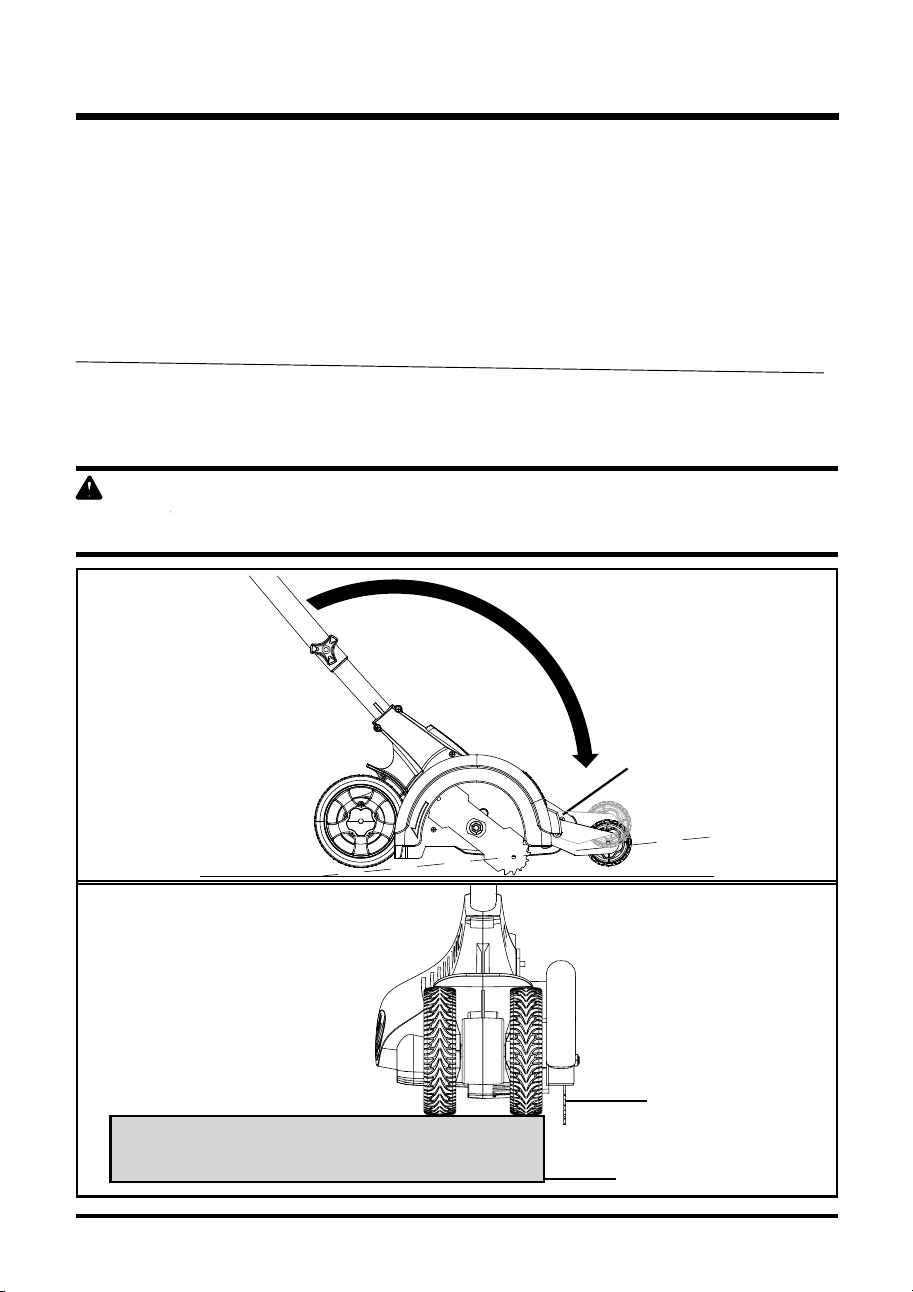
21
cÓMO aJUSTaR La PROFUNdIdad dE cORTE (Vea las figuras 8 y 9.)
Se puede ajustar la rueda frontal para obtener un corte más, o menos, profundo, y alargar la vida
de la cuchilla. Cambie la profundidad del rebordeo con que se envió a la profundidad deseada
haciendo lo siguiente:
• Espere que la cuchilla se detenga completamente.
• DESENCHUFE LA HERRAMIENTA.
• Afloje la perilla para ajuste y mueva la rueda hacia arriba para aumentar la profundidad o
hacia abajo para reducirla.
• Luego de efectuar el ajuste, apriete con seguridad la perilla para ajuste.
NOTA:
Inicialmente ajuste la profundidad de la cuchilla entre y 1,25 y 2,5 cm. (½ y 1 pulgada) Haga un corte
poco profundo para comprobar la profundidad de corte. Si es necesario ajustar la profundidad de corte,
se debe efectuar de manera progresiva hasta alcanzar la profundidad deseada. Para alargar la vida
útil de la cuchilla, mantenga la profundidad inicial a un mínimo y aumente la profundidad solamente
cuando se desgaste la cuchilla.
a d V E R T E N c I a
La hierba muy crecida podría trabarse en la cubierta protectora. Reduzca la profundidad de corte a
un mínimo para ayudar a reducir tal situación.
Fig. 8
Fig. 9
cUcHILLa
BORdILLO
PROFUNdIdad dE
La cUcHILLa
PaRa REdUcIR
La PROFUNdIdad
PaRa aUMENTaR
La PROFUNdIdad
PERILLa PaRa
aJUSTE
FUNCIONAMIENTO

22
CONSEJOS PARA EL FUNCIONAMIENTO
NOTA: El rebordeador necesita una gran cantidad de energía y no se le debe hacer funcionar
simultáneamente con otras herramientas o aparatos en el mismo circuito eléctrico.
• Ajuste la profundidad inicial de corte en 2,54 cm (1 pulg.) y coloque la guía de rebordeo en la
posición baja.
• Antes de arrancar el rebordeador alinéelo de modo que la guía del rebordeador se apoye
contra el borde de la superficie pavimentada. Al rebordear, ambas ruedas posteriores deben
estar asentadas sobre la superficie pavimentada.
NOTA:
La hierba muy crecida que llega hasta la superficie pavimentada podría trabarse en la cubierta
protectora Podría ser necesario efectuar un corte inicial con una profundidad de corte reducida.
• Para evitar los culatazos, presione la manija hacia abajo para que la cuchilla esté arriba de la
cubierta protectora.
• Encienda el interruptor y, sin mover la herramienta, deje girar la cuchilla.
• Eleve lentamente la manija para bajar la cuchilla. Llegue al borde de la superficie pavimentada
y comience el rebordeo.
P R E C A U C I Ó N
No trate de despejar la cámara de la cuchilla botando o golpeando la herramienta en el suelo. Eso
podría dañar la unidad. Mantenga las manos alejadas de la guía de rebordeo y de la cuchilla al
limpiarlos ya que durante el rebordeo ellos se vuelven puntiagudos.
Luego mueva lentamente la herramienta hacia adelante a lo largo del borde de la superficie
pavimentada, manteniendo la guía de rebordeo ligeramente presionada sobre el borde pavimentado.
Al rebordear por primera vez cada temporada, es mejor avanzar lentamente debido a que al principio
de la estación la hierba es más gruesa. El rebordeo subsiguiente se efectúa más rápidamente. Si la
herramienta se detiene, regrésela entre tres y cinco centímetros (una o dos pulgadas) hasta que la
cuchilla regrese a su velocidad normal. Al rebordear se podrían producir chispas al golpear piedras.
Eso es normal. Por motivo de seguridad eléctrica y para evitar que se obstruya la cámara de la
cuchilla, no trate de rebordear cuando la hierba o el suelo estén mojados. Si es necesario rebordear
bajo condiciones que hacen que la cámara de la cuchilla se obstruya, suelte el gatillo, espere que la
cuchilla se detenga completamente, DESENCHUFE LA HERRAMIENTA, abra la compuerta y quite
el material con una varilla. Continuar operando la herramienta obstruida recarga seriamente el motor.
A D V E R T E N C I A
Asegúrese de que las demás personas y las mascotas se encuentren por lo menos a 30 metros
(100 pies) de distancia del área de trabajo.
A D V E R T E N C I A
Antes de efectuar trabajos de jardinería o abrir surcos, inspeccione el terreno y asegúrese de que
no hay cables u otros objetos enterrados o expuestos que pudieran crear un peligro o interferir con
el funcionamiento del rebordeador. Ajuste la profundidad solamente a la necesaria para el trabajo.
No sobrecargue la herramienta. Si la herramienta trata de detenerse, retroceda lentamente y espere
a que la cuchilla regrese a la velocidad normal.
FUNCIONAMIENTO

23
A D V E R T E N C I A
Al dar servicio, use solamente repuestos idénticos. Usar cualquier otro repuesto podría provocar
peligros o crear daños al producto.
A D V E R T E N C I A
Al operar herramientas eléctricas o al crear polvo, use siempre gafas de seguridad o gafas de
seguridad con protecciones laterales. Si la operación es polvorienta, use además una careta.
A D V E R T E N C I A
Antes de inspeccionar, limpiar o dar servicio a la unidad, pare el motor, espere que todas las piezas
móviles se detengan y desconéctela de la fuente de alimentación. No seguir estas instrucciones
podría resultar en lesiones personales graves o daños a la propiedad.
MANTENIMIENTO GENERAL
Evite usar solventes al limpiar las piezas plásticas. La mayoría de plásticos son susceptibles a
daños debido a los distintos tipos de solventes comerciales y se podrían dañar al usar solventes.
Use paños limpios al remover suciedad, polvo, aceite, grasa, etc.
En ningún momento deje que líquido para frenos, gasolina, productos a base de petróleo, aceite
para penetración, etc. entre en contacto con las piezas de plástico. Los químicos podrían dañar,
debilitar o destruir el plástico, resultando en lesiones personales graves.
A D V E R T E N C I A
Pare el motor y desenchufe el rebordeador siempre que tenga que alejarse de la máquina.
Desenchufe el rebordeador antes de despejar la cubierta protectora de la cuchilla y al hacer
reparaciones, ajustes, inspecciones, etc.
Mantenga apretados los pernos, tuercas y tornillos.
A menudo usted mismo podrá hacer los ajustes y reparaciones aquí descritos. Para hacer otras
reparaciones, haga que un concesionario autorizado le dé servicio al producto.
A D V E R T E N C I A
No intente afilar la cuchilla. No obedecer esta advertencia podría producir lesiones personales
graves o daños a la propiedad.
MANTENIMIENTO
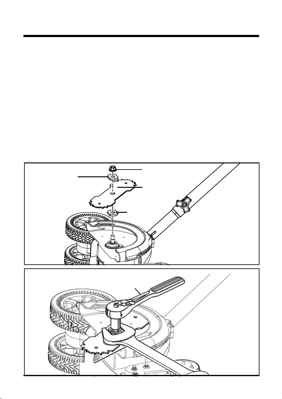
ARANDELA
EMBRIDADA
EXTERNA
ARANDELA
EMBRIDADA
INTERNA
TUERCA DE
LA CUCHILLA
CUCHILLA
24
CÓMO REEMPLAZAR LA CUCHILLA (Vea las figuras 10 y 11.)
Remplace las cuchillas dañadas o desgastadas. Para aumentar la vida útil de la cuchilla, mantenga
la profundidad inicial a un mínimo y aumente la profundidad solamente cuando se desgaste la
cuchilla.
• Pare el motor y desenchufe el rebordeador.
• Con una llave de 26 mm, sostenga la arandela embridada interna.
• Con una llave de cubos de 16 mm, gire la tuerca de la cuchilla en el sentido contrario al de las
agujas del reloj para aflojarla.
• Saque la tuerca de la cuchilla, la arandela embridada externa, la cuchilla y la arandela
embridada interna.
• Instale nuevamente la arandela embridada interna en el eje del rebordeador.
• Coloque la cuchilla nueva en el centro de la arandela embridada interna, asegurándose de que
la cuchilla se asienta planamente.
• Instale la arandela embridada externa en el eje del rebordeador.
• Con una llave de 26 mm, sostenga la arandela embridada interna.
• Instale la tuerca de la cuchilla en el eje del rebordeador.
• Con una llave de cubos de 16 mm, gire la tuerca de la cuchilla en el sentido de las agujas del
reloj y apriétela con seguridad.
Fig. 10
Fig. 11
LLAVE DE
CUBOS DE 16 mm
LLAVE DE 26 mm
MANTENIMIENTO

25
CÓMO ALMACENAR EL REBORDEADOR
• Asegúrese de que la herramienta esté desenchufada.
• Antes del almacenamiento quite y desaloje los escombros de la parte externa del rebordeador y
del interior de la cubierta protectora. Se ser necesario, se debe almacenar el rebordeador
colgándolo de un gancho por la manija.
• Desaloje todo material extraño del rebordeador.
• Almacénelo en un lugar inaccesible para los niños.
• Manténgalo alejado de agentes corrosivos tales como productos químicos para el jardín y sal
contra el hielo.
PRECAUCIÓN:
NO CUELGUE EL REBORDEADOR DEL GATILLO NI DEL CORDÓN
ELÉCTRICO.
NOTA: No almacene la herramienta cerca de fertilizantes o productos químicos. Ello podría causar rápida
corrosión.
MANTENIMIENTO

26
El motor no arranca cuando
se presiona el interruptor
de gatillo
1. El cordón eléctrico no está
enchufado o se ha soltado.
1. Enchufe el cordón
eléctrico.
2. El cortacircuitos de la casa
se ha disparado.
2. Revise el cortacircuitos.
RESOLUCIÓN DE AVERÍAS
PROBLEMA CAUSAS POSIBLES SOLUCIONES

27
LÍNEA TELEFÓNICA PARA AYUDA DE GREENWORKS (1 888 90WORKS):
GARANTÍA LIMITADA DE CUATRO AÑOS
Por este medio y por un período de
defectos en materiales, piezas o mano de obra al comprador original que cuente con una prueba
de compra. GREENWORKS, a su sola discreción reparará o reemplazará, sin costo alguno
para el cliente, cualquier pieza defectuosa, siempre y cuando se haya hecho uso normal de ella.
Esta garantía es válida solamente para unidades utilizadas de manera personal y que no hayan
sido utilizadas o alquiladas para uso industrial o comercial, y que hayan recibido mantenimiento
de acuerdo a las instrucciones que aparecen en el manual del propietario que se suministró con
el producto nuevo.
ARTÍCULOS QUE NO CUBRE LA GARANTÍA:
1. Cualquier pieza que se haya vuelto inoperante debido a mal uso, uso comercial, abuso,
descuido, accidente, mantenimiento inapropiado o alteración; o
2. La unidad, si no ha sido operada o si no se le ha dado mantenimiento de acuerdo al
manual del propietario; o
3. Desgaste normal, excepto según se indica a continuación;
4. Artículos de mantenimiento rutinario tales como lubricantes, afilado de cuchillas;
5. Deterioro normal del acabado exterior debido al uso y la exposición al entorno.
Se puede obtener servicio relacionado con la garantía llamando de lunes a viernes entre las
9 a.m. y las 5 p.m. a nuestra línea gratis para ayuda, el 1-888-909-6757 (1-888-90WORKS).
CARGOS DE TRANSPORTE:
Los cargos de transporte por el traslado de cualquier unidad de equipo o accesorio eléctrico son
responsabilidad del comprador. El comprador es responsable de pagar los cargos de transporte
de cualquier pieza presentada para reemplazo de acuerdo a esta garantía a menos que
GREENWORKS solicite por escrito tal retorno.
YEAR
AÑOS
LIMITED WARRANTY
GARANTÍA
LIMITADA
3
tres (3) años GREENWORKS garantiza este producto contra
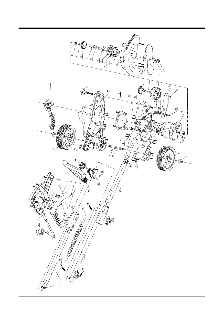
28
DIAGRAMA DE COMPONENTES

29
aRTIcULO No. PIEZa No. dEScRIPTION caNTIdad
1 3221037 onreP 1
sorelbaT A8140333 2 2
3 33301261 allihcuC 1
4 3220351 sonreP 3
5 34103263-1 allihcuc al ed atreibuC 1
6 34908261 Anillo para sello
Pernos
Arandelas planas
Arandelas
Cubierta de transmisión
Cojinete
Eje fijo
Llave plana
Rueda de engranaje
Arandela
Cojinete
Motor
Tuercas
Arandela
Tuerca
Barra para ajuste
Rueda frontal de 3 pulgadas
Barra
Cubiertas de las ruedas
Torsión
Carcaza derecha
Pernos
Cubierta protectora
Carcaza izquierda
Perilla de sujeción
Cubierta externa
Arandelas para ejes
Conjunto de la rueda de 6 pulgadas
Pernos
Collarín inferior
Sujetadores del cordón
Tornillos
Eje de las ruedas posterior
es
Clavija
Tuerca
Conjunto de la rueda izquierda de 6 pulgadas
Tubo inferior
1
7 3220811 4
8 3290305 4
9 3290675 4
10 33103261 1
11 32109261 1
12 33208261 1
13 32902261 1
14 33508261 1
15 3290448 1
16 32108261 1
17 36101263-1 1
18 32208261 3
19 3220898 1
20 32907152 1
21 33303263 1
22 34119263-1 1
23 33203263 1
24 3411799C 3
25 33401263 1
26 34102263-1 1
27 3220505 30
28 34105263 1
29 34101263-1 1
30 34110263 1
31 34104263-1 1
32 33304261 3
33 3411799-4 1
34 3220552 2
35 34113263 1
36 3410302 3
37 3220905 3
38 33202263 1
39 32988261 1
40 32204100 1
41 3411799-3 1
42 33301263-1 1
SAZEIP ED ATSIL

30
aRTIcULO No.
PIEZa No. dEScRIPTION caNTIdad
43 33302262-1 1
44 3110182-6 1
45 34101266 1
46 3110282-6 1
47 3290205 1
48 33301262-1 1
49 36511154 2
50 36901263 1
51 34115263 4
52 34106263-1 1
53 34107263-1 1
54 36301263-1 1
55 3420102-1 1
56 36401263 1
57 34901263
58 3410835-6
59 3220436
60 34120263
61 34121263
Tubo central
Conjunto de la manija auxiliar
Tubo de bloqueo para la manija auxiliar
Perilla de la manija auxiliar
Tuerca
Tubo superior
Tapas del conector
Alambre
Collarines superiores
Manija izquierda
Manija derecha
Interruptor
Retenedor
Cordón eléctrico
Esponja
Gire tapa
Cierre para el asidero
Cámara
Cámara
1
2
2
1
1
SAZEIP ED ATSIL

NOTES

LÍNEA TELEFÓNICA GRATIS PARA AYUDA: 1-888-90WORKS
(888.909.6757)
Greenworks Tools
P.O. Box 1238
Mooresville, NC 28115