Loading ...
Loading ...
Loading ...
FRANÇAIS
14
Field Calibration Check
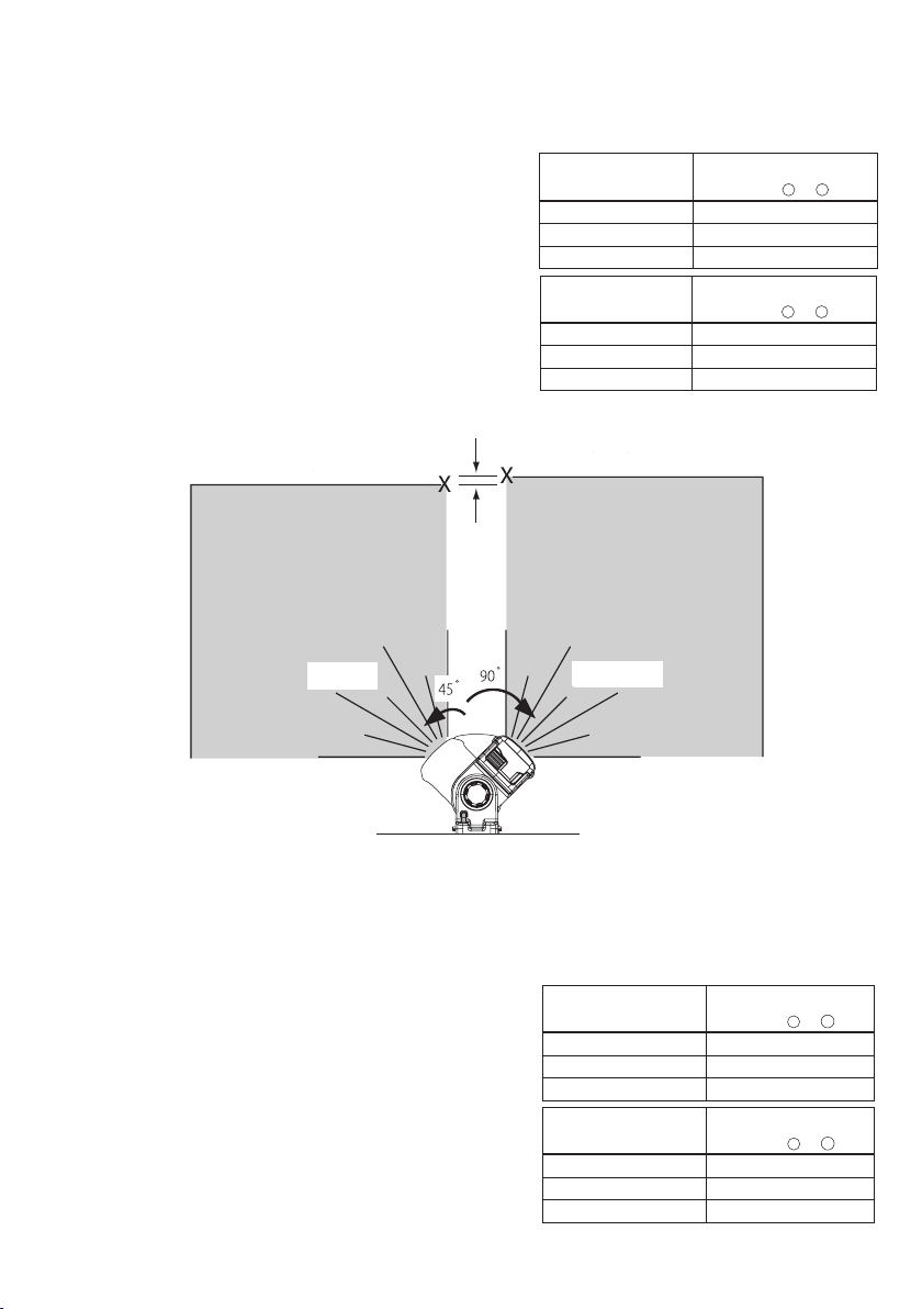
Checking Accuracy – Horizontal Beam, Scan Direction (Fig.F)
Checking the horizontal scan calibration of the laser requires two walls at least 30' (9 m) apart. It is important to conduct a
calibration check using a distance no shorter than the distance of the applications for which the tool will beused.
1. Attach the laser to a wall using its pivot bracket. Make sure the laser is
facing straightahead.
2. Turn on the laser's horizontal beam and pivot the laser approximately
45˚ so that the right-most end of the laser line is striking the opposing
wall at a distance of at least 30' (9 m). Mark the center of the beam (a).
3. Pivot the laser approximately 90˚ to bring the left-most end of the laser
line around to the mark made in Step 2. Mark the center of the beam (b).
4. Measure the vertical distance between themarks.
• If the measurement is greater than the values shown below, the laser
must be serviced at an authorized servicecenter.
Contrôle de précision - faisceau horizontal, direction d’inclinaison (Fig.G)
Le contrôle de calibrage horizontal de l’inclinaison du laser nécessite un mur d’au moins 9m (30’) de longueur. Il importe
d’effectuer le contrôle de calibrage en utilisant une distance qui n’est pas inférieure à la distance des applications pour lesquelles
l’outil serautilisé.
1. Fixez le laser à une extrémité du mur en utilisant son supportpivotant.
2. Allumez le faisceau horizontal du laser et faites-le pivoter vers le côté
opposé du mur et approximativement parallèle au muradjacent.
3. Marquez le centre du faisceau à deux emplacements (a, b) éloignés
d’au moins 9m (30’).
4. Repositionnez le laser sur le côté opposé dumur.
5. Allumez le faisceau horizontal du laser et faites-le pivoter pour revenir
vers la première extrémité du mur et approximativement parallèle au
muradjacent.
6. Réglez la hauteur du laser de sorte que le centre du faisceau soit aligné
avec le repère le plus proche (b).
7. Marquez le centre du faisceau (c) directement au-dessus ou
au-dessous du repère le plus éloigné (a).
Fig. F
STEP 1
a
b
STEP 2
STEP 3
STEP 4
STEP 2
STEP 3
ÉTAPE 1
ÉTAPE 2
ÉTAPE 3
ÉTAPE 4
ÉTAPE 2
ÉTAPE 3
Distance entre les
murs
Distance autorisée
entre
a
et
b
30' 1/8"
40' 5/32"
50' 7/32"
Distance
entre les murs
Distance autorisée
entre
a
et
b
9.0 m 3.1 mm
12.0 m 4.2 mm
15.0 m 5.2 mm
Distance
entre les murs
Distance autorisée
entre
a
et
c
30' 1/4"
40' 5/16"
50' 13/32"
Distance
entre les murs
Distance autorisée
entre
a
et
c
9.0 m 6.2 mm
12.0 m 8.3 mm
15.0 m 10.4 mm
Loading ...
Loading ...
Loading ...