
Owner's Manual
£RAFTSMAN
15.5 HP
ELECTRIC START
42" MOWER
AUTOMATIC
LAWN TRACTOR
Model No.
917.271060
e Safety
• Assembly
• Operation
• Maintenance
• Repair Parts
CAUTION:
Read and follow all Safety
Rules and Instructions before
operating this equipment.
For answers to yourquestions
about this product, Call:
1-800-659-5917
Sears Craftsman Help Line
5 am- 5 pro, Mon- Sat
Sears, Roebuck and Co., Hoffman Estates, II 60179
Visit our Craftsman website:www.sears.com/craftsman

Warranty ............................................... 2
Safety Rules ......................................... 2
Product Specifications .......................... 5
Assembly .............................................. 7
Operation ............................................ 10
Maintenance Schedule ...................... 17
Service and Adjustments.................... 21
Storage ............................................... 28
Troubleshooting ................................. 29
Repair Parts........................................ 34
Parts Ordering ..................... Back Cover
LIMITED TWO YEAR WARRANTY ON CRAFTSMAN RIDING EQUIPMENT
Fortwo (2) years from the date of purchase, if this Craftsman Riding Equipment is
maintained, lubricatod and tuned up according to the instructionsin the owner's
manual, Sears will repair or replace, free of charge, any parts found to be defective in
matedal or workmanship.
This Warranty does not cover:
• Expendable items which become worn dudng normal use, such as blades, spark
plugs, air cleaners, belts, etc.
• Tire replacement or repair caused by punctures from outside objects, such as nails,
thorns, stumps, or glass.
• Repairs necessary because of operator abuse, negligence, improper storage or
accident or the failure to maintain the equipment according to the instructions
contained in the owner's manual.
• Riding equipment used for commercial or rental purposes.
LIMITED 90 DAY WARRANTY ON BATI'ERY
For ninety (90) days from date of purchase, if any battery includedwith this riding
equipment proves defective in matedal or workmanship and our testing determines the
battery will not hold a charge, Sears will replace the battery at no charge. In-home
warranty service on your Craftsman riding equipment is available at no charge for 30
days from the date of purchase. Please contact your nearest service center. After 30
days from the date of purchase, warranty service is available by taking your Craftsman
dding equipment to your nearest Sears Service Center. (In-home warranty service will
still be available after 30 days from the date of purchase but a standard tdp charge will
apply). This warranty applies only while this product is in the United States. This
Warranty gives you specific legal rights, and you may also have other rights which may
vary from state to state.
Sears, Roebuck and Co., D/817 WA, Hoftman Estates, IL 60179
IMPORTANT: This cutting machine is
capable of amputating hands and feet
and throwing objects. Failure to observe
the following safety instructions could
result in serious injury or death.
GENERAL OPERATION
• Read, understand, and follow all
instructions in the manual and on the
machine before starting.
• Only allow responsible adults, who are
familiar with the instructions, to
operate the machine.
• Clear the area of objects such as
rocks, toys, wire, etc., which could be
picked up and thrown by the blade.
• Be sure the area isclear of other
people before mowing. Stop machine
if anyone enters the area.
• Never carry passengers.
• Do not mow in reverse unless abso-
lutely necessary. Always look down
and behind before and while backing.
• Be aware of the mower discharge
direction and do not point itat anyone.
Do not operate the mower without
either the entire grass catcher or the
guard in place.
• Slow down before tuming.
• Never leave a running machine
unattended. Always tum off blades, set
parking brake, stop engine, and
2 remove keys before dismounting.
• Turn off blades when not mowing.
• Stop engine before removing grass
catcher or unclogging chute.
• Mow only in daylight or good artificial
light.
• Do not operate the machine while
under the influence of alcohol or
drugs.
• Watch for traffic when operating near
or crossing roadways.
• Use extra care when loading or
unloading the machine into a trailer or
truck.
• Data indicates that operators, age 60
years and above, are involved in a
large pementage of riding mower-
related injuries, These operators
should evaluate _eir ability to operate
the dding mower safely enough to
protect themselves and others from
esdous injury.
SLOPE OPERATION
Slopes are a major factor related to Ioes-
of-control and tipover accidents, which
can result in severe injuryor death. All
slopes require extra caution. If you
cannot back up the slope or if you feel
uneasy on it, do not mow it.
DO:
• Mow up and down slopes, not across.
• Remove obstacles such as rocks, tree
limbs, etc.
• Watch for holes, ruts, or bumps.
Uneven terrain could overturn the
machine. Tall grass can hide ob-
stacles.
• Use slow speed. Choose a low gear
so that you willnot have to stop or shift
while on the slope.
• Follow the manufacturer's recommen-
dations for wheel weights or counter-
weights to improve stability.
• Use extra care with grass catchers or
other attachments. These can change
the stability of the machine.
• Keep all movement on the slopes slow
and gradual. Do not make sudden
changes in speed or direction.
• Avoid starting or stopping on a slope. If
tires lose traction, disengage the
blades and proceed slowly straight
down the slope.
DO NOT:
• Do not tum on slopes unless neses-
sary, and then, turn slowly and
gradually downhill, if possible.
• Do not mow near dropoffs, ditches, or
embankments. The mower could
suddenly turn over if a wheel is over
the edge of a cliff or ditch, or if an edge
caves in.
• Do not mow on wet grass. Reduced
traction could cause sliding.
• Do not try to stabilize the machine by
putting your foot on the ground.
• Do not use grass catcher on steep
slopes.
CHILDREN
Tragic accidents can occur if the operator
is not alert to the presence of children.
Children are often attracted to the
machine and the mowing activity.Never
assume that children will remain where
you lest saw them.
• Keep children out of the mowing area
and under the watchful care of another
responsible adult.
• Be alert and turn machine off if
children enter the area.
• Before and when backing, look behind
and down for small children.
• Never carry children. They may fall off
and be seriously injured or interfere
with safe machine operation.
• Never allow children to operate the
machine.
• Use extra care when approaching
blind comers, shrubs, trees, or other
objects that may obscure vision.
SERVICE
• Use extra care in handling gasoline
and other fuels. They are flammable
and vapors are explosive.
Use only an approved container.
Never remove gas cap or add fuel
with the engine running. Allow en-
gine to cool before refueling. Do
not smoke.
Never refuel the machine indoors.
Never store the machine or fuel
container inside where there is an
open flame, such as a water heat-
er.
• Never run e machine inside a closed
area.
3
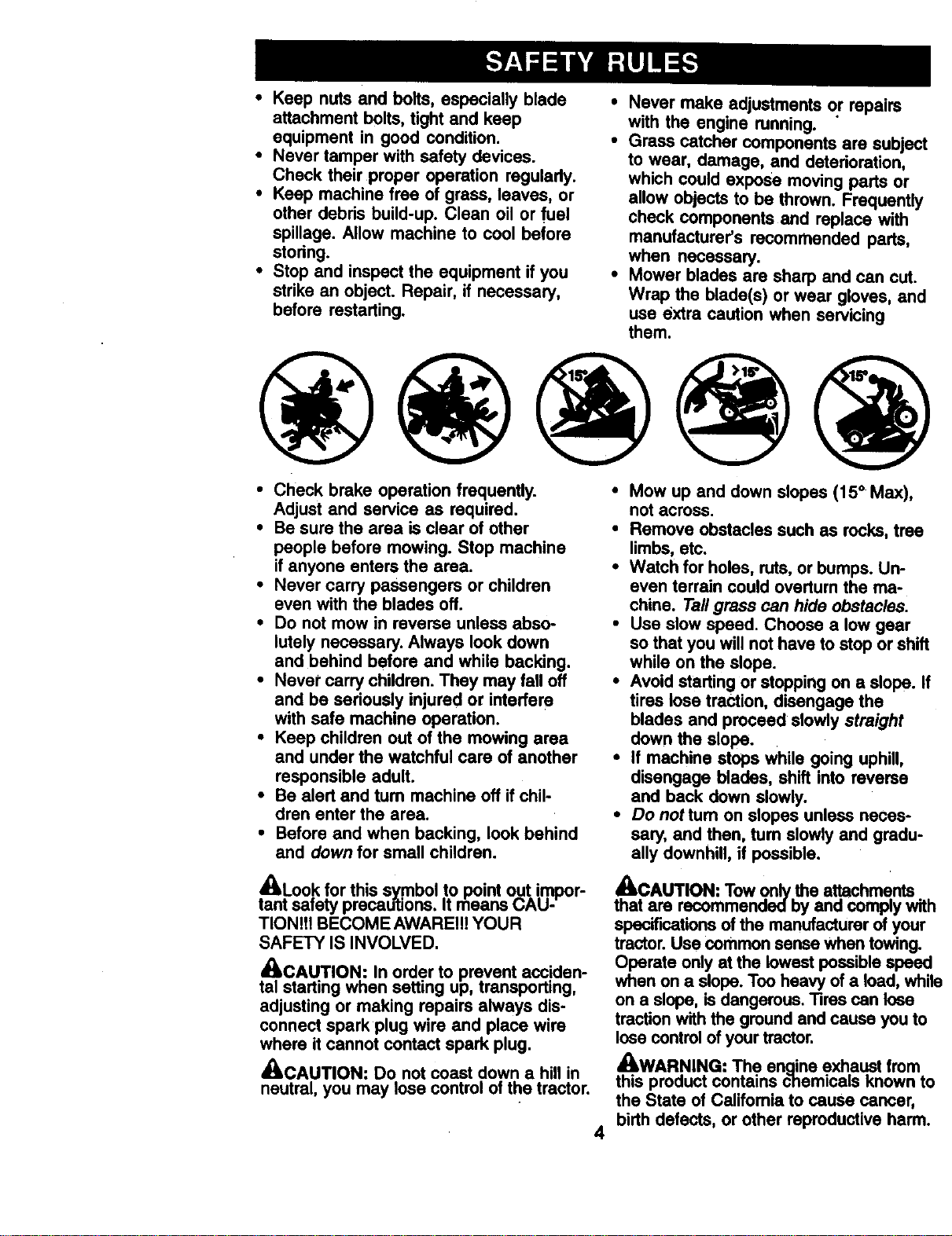
• Keep nuts and bolts, especially blade
attachment bolts, tight and keep
equipment in good condition.
• Never tamper with safety devices.
Check their proper operation regularly.
• Keep machine free of grass, leaves, or
other debris build-up. Clean oil or fuel
spillage. Allow machine to cool before
stodng.
• Stop and inspect the equipment if you
strike an object. Repair, if necessary,
before restarting.
Never make adjustments or repairs
with the engine running.
Grass catcher components are subject
to wear, damage, and deterioration,
which could expose moving parts or
allow objects to be thrown. Frequently
check components and replace with
manufacturer's recommended parts,
when necessary.
Mower blades are sharp and can cut.
Wrap the blade(s) or wear gloves, and
use extra caution when servicing
them.
• Check brake operation frequently.
Adjust and service as required.
• Be sure the area is clear of other
people before mowing. Stop machine
if anyone enters the area.
• Never carry passengers or children
even with the blades off.
• Do not mow in reverse unless abso-
lutely necessary. Always look down
and behind before and while backing.
• Never carry children. They may fall off
and be seriously injured or interfere
with safe machine operation.
• Keep children out of the mowing area
and under the watchful care of another
responsible adult.
• Be alert and turn machine off if chil-
dren enter the area.
• Before and when backing, look behind
and down for small children.
A_,Look for this symbol to point out impor-
tant safety precadtions. It means u/_u-
TIONIt! BECOME AWARE!!! YOUR
SAFETY IS INVOLVED.
_CAUTION: In order to prevent acciden-
tal starting when setting up, transporting,
adjusting or making repairs always dis-
connect spark plug wire and place wire
where it cannot contact spark plug.
,_kCAUTION: Do not coast down a hill in
neutral, you may lose control of the tractor.
4
• Mow up and down slopes (15° Max),
not across.
• Remove obstacles such as rocks, tree
limbs, etc.
• Watch for holes, ruts, or bumps. Un-
even terrain could overturn the ma-
chine. Tallgrass can hide obstacles.
• Use slow speed. Choose a low gear
so that you will nothave to stop or shift
while on the slope.
• Avoid starting or stopping on a slope. If
tires lose traction, disengage the
blades and proceed slowly straight
down the slope.
• If machine stops while going uphill,
disengage blades, shift into reverse
and back down slowly.
• Do not tum on slopes unless neces-
sary, and then, tum slowly and gradu-
ally downhill, if possible.
_CAUTION: Tow only the attachments
that are recommended by and comply with
specifications of the manufacturer of your
tractor. Use common sense when towing.
Operate only at the lowest possible speed
when on a slope. TOOheavy of a load, while
on a slope, is dangerous. "liras can lose
traction with the ground and cause you to
lose control of your tractor.
_WARNING: The enaine exhaust from
this product contains chemicals known to
the State of California to cause cancer,
birth defects, or other reproductive harm.
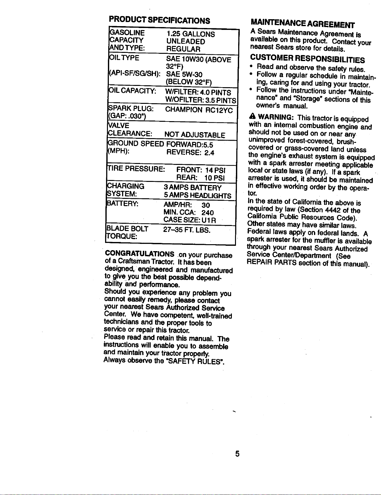
PRODUCT SPECIFICATIONS
GASOLINE
CAPACITY
ANDTYPE:
OILTYPE
API-SF/SG/SH):
OIL CAPACITY:
1.25 GALLONS
UNLEADED
REGULAR
SAE 10W30 (ABOVE
32°F)
SAE 5W-30
(BELOW 32°FI
W/FILTER: 4.0 PINTS
W/OFILTER: 3.5 PINTS
CHAMPION RC12YCSPARK PLUG:
GAP: .030")
VALVE
CLEARANCE: NOT ADJUSTABLE
GROUND SPEED FORWARD:5.5
(MPH): REVERSE: 2.4
I'IRE PRESSURE: FRONT: 14 PSI
REAR: 10 PSI
.3HARGING 3AMPS BATTERY
_YSTEM: 5 AMPS HEADLIGHTS
_TTERY: AMP/HR: 30
MIN. CCA: 240
CASE SIZE: U1 R
3LADE BOLT 27-35 FT. LBS.
rORQUE:
CONGRATULATIONS .on your purchsse
of a Craftsman Tractor. It has been
designed, engineered and manufactured
to give you the best possible depend-
ability and performance.
Should you experience any problem you
cannot easily remedy, please contact
your nearest Sears Authorized Service
Center. We have competent, well-trained
technicians and the proper tools to
service or repair this tractor.
Please read and retain this manual. The
instructions will enable you to assemble
and maintain your tractor properly.
Always observe the =SAFETY RULES'.
MAINTENANCE AGREEMENT
A Sears Maintenance Agreement is
available on this product. Contact your
nearest Sears store for details,
CUSTOMER RESPONSIBILITIES
• Read and observe the safety rules.
• Follow a regular schedule in maintair
ing, cedng for and using your tractor.
• Follow the instructionsunder "Mainte
nance" and "Storage" sections of this
owner's manual.
A WARNING: This tractor isequipped
with an intemal combustion engine and
should not be used on or near any
unimproved forest-covered, brush-
covered or grass-covered land unless
the engine's exhaust system is equippe_
with a spark arrester meeting applicable
local or state laws (if any). Ifa spark
arrester is used, itshould be maintained
in effective working order by the opera-
tor.
In the state of California the above is
required by law (Section 4442 of the
California Public Resources Code).
Other states may have similar laws.
Federal laws apply on federal lands. A
spark arrester for the muffler is available
through your nearest Sears Authorized
Service Center/Dapartment (See
REPAIR PARTS section of this manual).
5
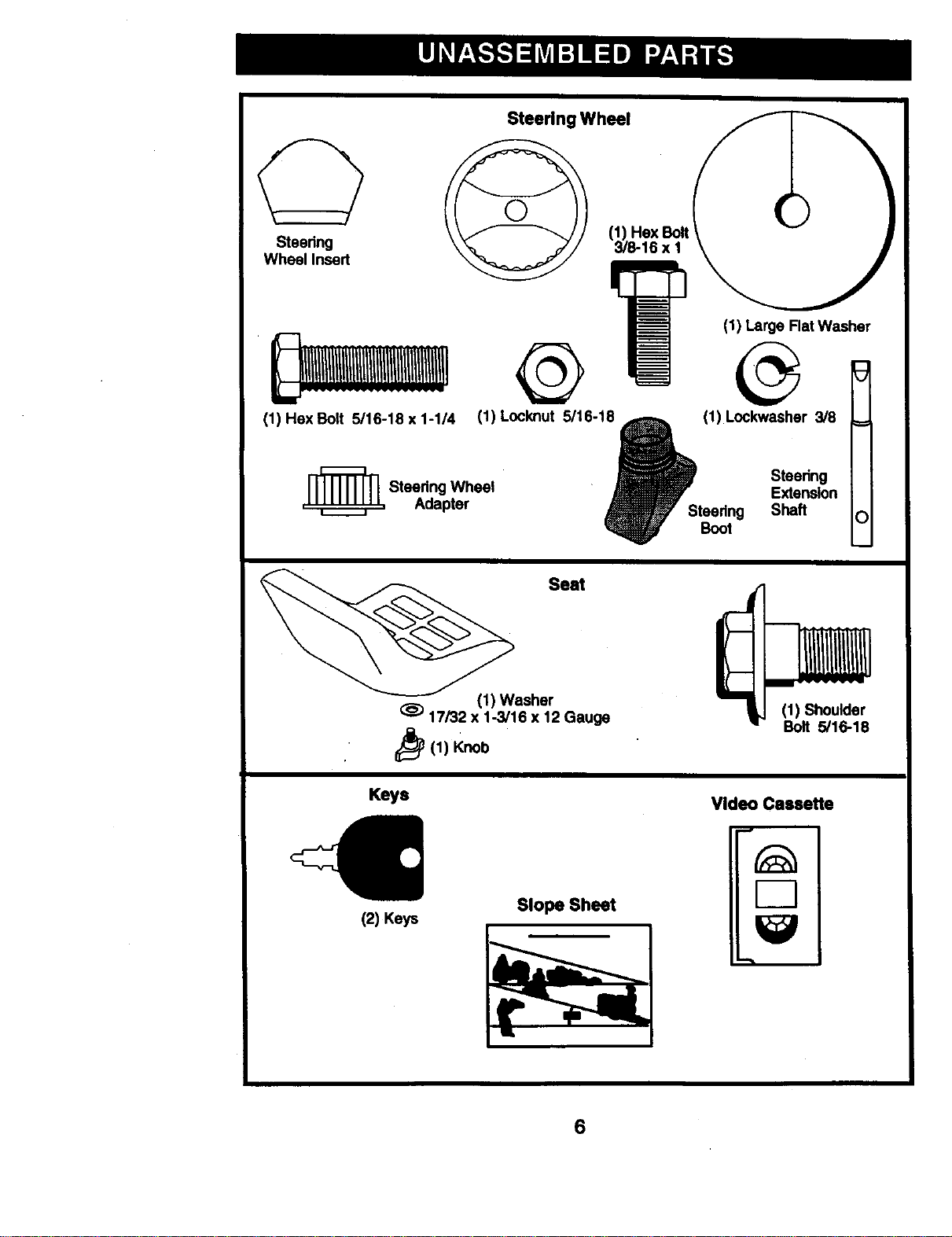
Steering Wheel
Steering
Wheel Insert
(1) Hex Bolt 5/16-18 x 1-1/4
=_ Steedng Wheel
Adapter
(1) Hex Bolt
3/8-16 x I
(1) Large Flat Washer
(1) Locknut 5/16-10 _ (1) Lockwashar 3/8
t
Steedng
Extension
Steedng Shaft
Boot
Seat
(1) Washer
17/32 x 1-3/16 x 12 Gauge
_(1) Knob
(1) Shoulder
Bolt 5/16-18
Keys
Video Cassette
(2) Keys
Slope Sheet
6
Your new tractor has been assembled at the factory with exception of those parts left
unassembled for shipping purposes. To ensure safe and proper operation of your
tractor all parts and hardware you assemble must be tightened securely. Use the
correct tools as necessary to insure proper tightness. Review the video cassette before
you begin.
TOOLS REQUIRED FOR
ASSEMBLY
A socket wrench set will make assembly
easier. Standard wrench sizes you need
are listed below.
(1) 9116" wrench (1) Pliers
(2) 1/2" wrench (1) Utility knife
(1) 3/4" socket with
ddve ratchet
(1) Tire pressure gauge
When dght or left hand is mentioned in
this manual, it means, from your point of
view, when you are in the operafing
position (seated behind the steering
wheel).
TO REMOVE TRACTOR FROM
CARTON
UNPACK CARTON
• Remove all accessible loose parts
and parts boxes from shipping carton.
• Cut, from top to bottom, along lines on
all four corners of shipping carton, and
lay panels fiat.
• Remove mower and packing mated-
als.
• Check for any additional loose parts or
boxes and remove.
BEFORE ROLLING TRACTOR OFF
SKID
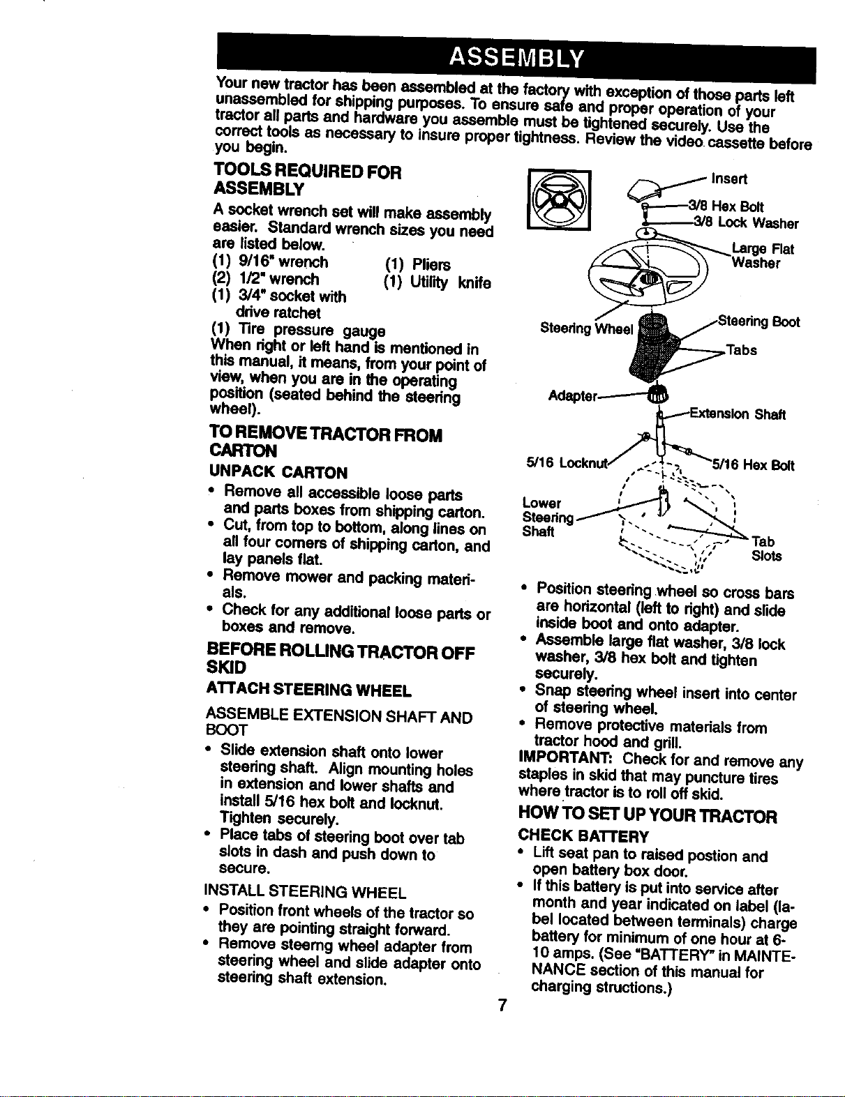
ATTACH STEERING WHEEL
ASSEMBLE EXTENSION SHAFT AND
BOOT
• Slide extension shaft onto lower
steedng shaft. Align mounting holes
in extension and lower shafts and
install 5/16 hex bolt and Iocknut.
Tighten securely.
• Place tabs of steering boot over tab
slots in dash and push down to
secure.
INSTALL STEERING WHEEL
• Position front wheels of the tractor so
they are pointing straight forward.
• Remove steemg wheel adapter from
steering wheel and slide adapter onto
steering shaft extension.
_ Insert
_---..-3/8 Hex Bolt
_---_3/8 Lock Washer
_Large Flat
_ Washer
/ ' Boot
Steedng Wheel
,Tabs
• Position steering wheel so cross bars
are horizontal (left to right) and slide
inside boot and onto adapter.
• Assemble large fiat washer, 3/8 lock
washer, 3/8 hex bolt and tighten
securely.
• Snap steering wheel insert into center
of steering wheel.
• Remove protective materials from
tractor hood and grill.
IMPORTANT: Check for and remove any
staples in skid that may puncture tires
where tractor is to roll off skid.
HOW TO SET UP YOUR TRACTOR
CHECK BATTERY
• Lift seat pan to raised postion and
open battery box door.
• If this battery is put into service after
month and year indicated on label (la-
bel located between terminals) charge
battery for minimum of one hour at 6-
10 amps. (See =BATTERY" in MAINTE-
NANCE section of this manual for
charging structions.)
7
Seat
Battery
Door
_rminal
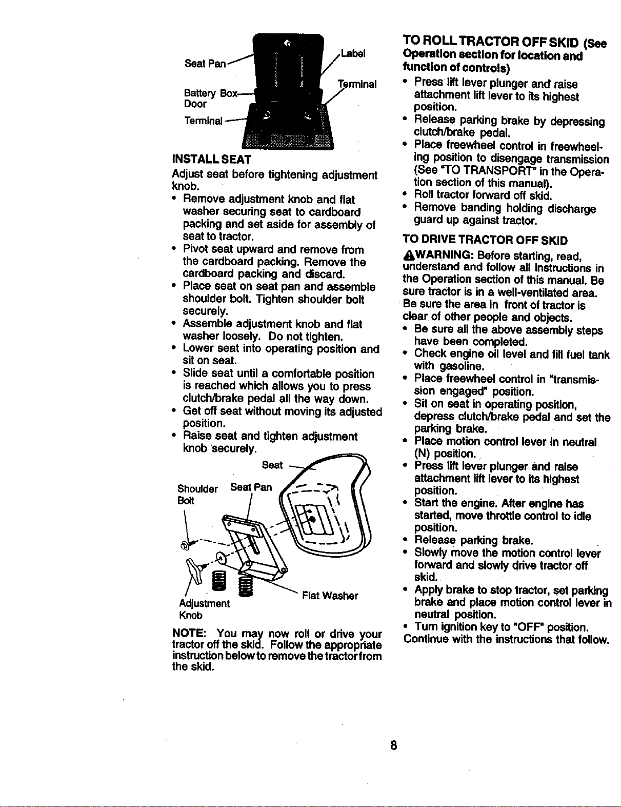
INSTALL SEAT
Adjust seat before tightening adjustment
knob.
• Remove adjustment knob and flat
washer securing seat to cardboard
packing and set aside for assembly of
seat to tractor.
• Pivot seat upward and remove from
the cardboard packing. Remove the
cardboard packing and discard.
• Place seat on seat pan and assemble
shoulder bolt. Tighten shoulder bolt
securely.
• Assemble adjustment knob and flat
washer loosely. Do not tighten.
• Lower seat into operating position and
sit onseat.
• Slide seat until a comfortable position
is reached which allows you to press
clutch/brake pedal all the way down.
* Get off seat without moving its adjusted
position.
• Raise seat and tighten adjustment
knob 'securely.
Seat
Shoulder Seat Pan
Bolt
Adjustment
Knob
NOTE: You may now roll or drive your
tractor off the skid. Follow the appropriate
instruction below to remove the tractor from
the skid.
TO ROLL TRACTOR OFF SKID (See
Operation section for location and
function of controls)
• Press lift lever plunger and"raise
attachment lift lever to its highest
position.
• Release parking brake by depressing
clutch/brake pedal.
* Place freewheel control in freewheel-
ing position to disengage transmission
(See =TO TRANSPORT" in the Opera-
tion section of this manual).
• Roll tractor forward off skid.
• Remove banding holding discharge
guard up against tractor.
TO DRIVE TRACTOR OFF SKID
AWARNING: Before starting, read,
understand and follow all instructionsin
the Operation section of this manual. Be
sure tractor is in a well-ventilated area.
Be sure the area in front of tractor Is
clear of other people and objects.
• Be sure all the above assembly steps
have been completed.
• Check engine oil level and fill fuel tank
with gasoline.
• Place freewheel control in "transmis-
sion engaged" position.
• Sit on seat in operating position,
depress clutch/brake pedal and set the
parking brake.
• Place motion control lever in neutral
(N) position.
• Press liftlever plunger and raise
attachment lift lever to its highest
position.
• Start the engine. After engine has
started, move throttle control to idle
position.
• Release parking brake.
• Slowly move the motion control lever
forward and slowly ddve tractor oft
skid.
• Apply brake to stop tractor, set parking
brake and place motion control lever in
neutral position.
•Tum ignitionkey to "OFF" position.
Continue with the instructions that follow.
8
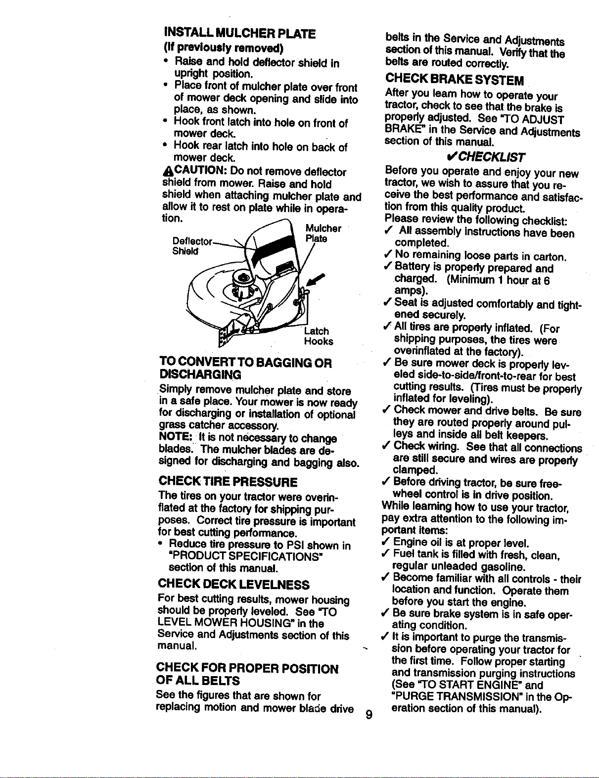
INSTALL MULCHER PLATE
(If previously removed)
• Raise and hold deflector shield in
upright position.
• Place front of mulcher plate over front
of mower deck opening and slide into
place, as shown.
• Hook front latch into hole on front of
mower deck.
• Hook rear latch into hole on back of
mower deck.
_CAUTION: Do not remove deflector
shield from mower. Raise and hold
shield when attaching mulcher plate and
allow it to rest on plate while in opera-
lion.
Mulchsr
Plate
Shield
Latch
Hooks
TO CONVERT TO BAGGING OR
DISCHARGING
Simply remove mulcher plate and store
in a safe place. Your mower is now ready
for discharging or installat'_n of optional
grass catcher accessory.
NOTE: It is not necesea_ to change
blades: The mulcher blades are de-
signed for discharging and begging also.
CHECK TIRE PRESSURE
The tires on your tractor were overin-
flated at the factory for shipping pur-
poses. Correct tire pressure is important
for best cuffing performance.
• Reduce tire pressure to PSI shown in
"PRODUCT SPECIFICATIONS"
section of this manual.
CHECKOECKLEVELNESS
For best cutting results, mower housing
should be properly leveled. See 'I"O
LEVEL MOWER HOUSING" in the
Service and Adjustments section of this
manual.
CHECK FOR PROPER POSITION
OF ALL BELTS
See the figures that are shown for
replacing motion and mower bla_e drive
9
belts in the Service and Adjustments
section of this manual. Verify that the
belts are routed correctly.
CHECK BRAKE SYSTEM
After you learn how to operate your
tractor, check to see that the brake is
properly adjusted. See =TO ADJUST
BRAKE" in the Service and Adjustments
section of this manual.
V' CHECKLIST
Before you operate and enjoy your new
tractor, we wish to assure that you re-
ceive the best performance and satisfac-
tion from this quality product.
Please review the following checklist:
,/ All assembly instructions have been
completed.
•/ No remaining loose parts in carton.
,/Battery is propedy prepared and
charged. (Minimum 1 hour at 6
amps).
,/Seat is adjusted comfortably and tight-
ened securely.
,/All tires are properly inflated. (For
shipping purposes, the tires were
ovednflated at the factory).
,/Be sure mower deck is properly lev-
eled side-to-side/front-to-rear for best
cutting results. (Tires must be properly
inflated for leveling).
•! Check mower and drive belts. Be sure
they are routed properly around pul-
leys and inside all belt keepers.
•/ Check wiring. See that all connections
are still secure and wires are properly
clamped.
•/ Before driving tractor, be sure free-
wheel control is in drive position.
While leaming how to use your tractor,
pay extra attention to the following im-
portant items:
/ Engine oil is at proper level.
,/Fuel tank is filled with fresh, clean,
regular unleaded gasoline.
,/Become familiar with all controls - their
location and function. Operate them
before you start the engine.
/ Be sure brake system is in safe oper-
ating condition.
4' It is important to purge the transmis-
sion before operating your tractor for .
the first time. Follow proper staking
and transmission purging instructions
(See "TO START ENGINE" and
"PURGE TRANSMISSION" in the Op-
eration section of this manual).
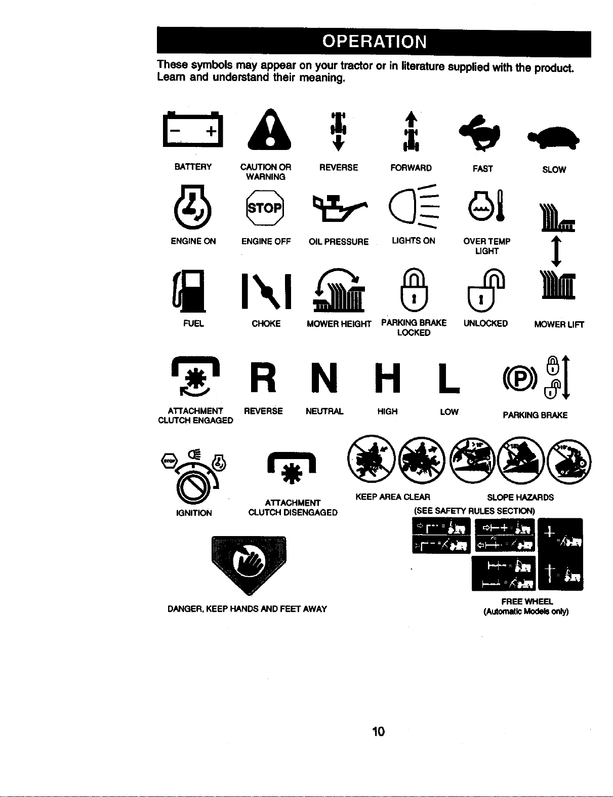
These symbols may appear on your tractor or in literature supplied withthe product.
Learn and understand their meaning.
BATTERY CAUTIONOR
WARNING
REVERSE FORWARD FAST SLOW
ENGINE ON ENGINE OFF OIL PRESSURE LIGHTSON OVERTEMP
LIGHT
FUEL CHOKE MOWERHEIGHT PARKINGBRAKE UNLOCKED MOWERLIFT
LOCKED
R N H
ATTACHMENT REVERSE NEUTRAL HIGH
CLUTCH ENGAGED
LOW PARKINGBRAKE
ATTACHMENT KEEPAREACLEAR SLOPE HAZARDS
IGNITION CLUTCH DISENGAGED (SEE SAFETYRULESSECTION)
DANGER,KEEP HANDSAND FEET AWAY
FREEWHEEL
(AutomaticModelso_y)
10
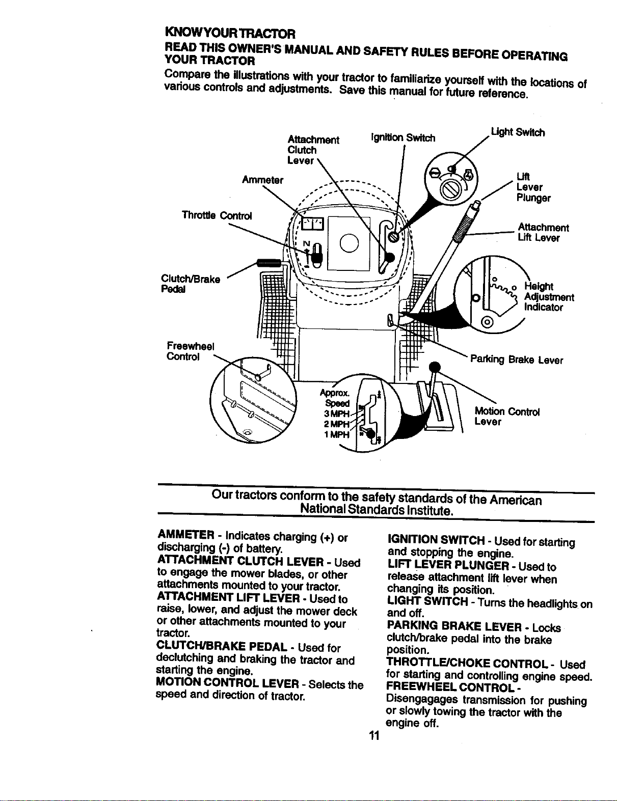
KNOWYOUR TRACTOR
READ THIS OWNER'S MANUAL AND SAFETY RULES BEFORE OPERATING
YOUR TRACTOR
Compare the illustrationswith your tractor to familiarize yourself with the locations of
various controls and adjustments. Save this manual for future reference.
Attachment
Clutch
IgrdtionSwitch
Ammeter
ThrotSe Control
UghtSwitch
Lift
J Lever
Plunger
Attachment
Lift Lever
ClutchlBrake
Pecl_
He,hi
Adjustment
Indicator
Freewheel
Control
Parking Brake Lever
Motion Control
Lever
Our tractors conform to the safety standards of the American
National Standards Institute,
AMMETER - Indicates charging (+) or
discharging (-) of battery.
ATTACHMENT CLUTCH LEVER - Used
to engage the mower blades, or other
attachraents mounted to your tractor.
ATTACHMENT LIFT LEVER - Used to
raise, lower, and adjust the mower deck
or other attachments mounted to your
tractor.
CLUTCH/BRAKE PEDAL - Used for
declutching and braking the tractor and
starting the engine.
MOTION CONTROL LEVER - Selects the
speed and direction of tractor.
11
IGNITION SWITCH - Used for starting
and stopping the engine.
LIFT LEVER PLUNGER - Used to
release attachment lift lever when
changing its position.
LIGHT SWITCH - Turns the headlights on
and off.
PARKING BRAKE LEVER - Locks
clutch/brake pedal into the brake
position.
THROTTLE/CHOKE CONTROL- Used
for starting and controlling engine speed.
FREEWHEEL CONTROL -
Disengagages transmission for pushing
or slowly towing the tractor with the
engine off.
The operation of any tractor can result in foreign objects thrown into
the eyes, which can result in severe eye damage. Always wear safety
glasses or eye shields while operating your tractor or performing any
adjustments or repairs. We recommend a wide vision safsty_nask
over spectacles or standard safety glasses.
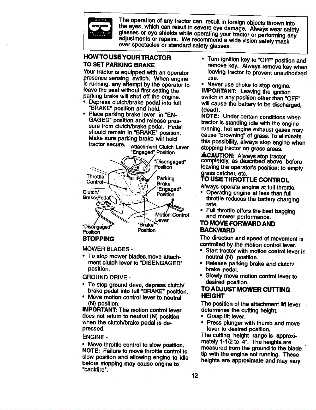
HOW TO USE YOUR TRACTOR
TO SET PARKING BRAKE
Yourtractor is equipped with an operator
presence sensing switch. When engine
is running, any attempt by the operator to
save the seat without first setting the
parking brake will shut off the engine.
• Depress clutch/brake pedal into full
=BRAKE" position and hold.
• Place parking brake lever in =EN-
GAGED" position and release pres-
sure from clutch/brake pedal. Pedal
should remain in =BRAKE" position.
Make sure parking brake will hold
tractor secure. Attachment Clutch Lever
• Tum ignitionkey to =OFF"position and
remove key. Always remove key when
leaving tractor to prevent unauthorized
use.
• Never use choke to stop engine.
IMPORTANT: Leaving the ignition
switch in any positionother than "OFF"
will cause the battery to be discharged,
(dead).
NOTE: Under certain conditions when
tractor is standing idle with the engine
running, hot engine exhaust gases may
cause =browning" of grass. To eliminate
this possibility,always stop engine when
stopping tractor on grass areas.
=Engagecr'Position _CA.U.TI.ON: Always.,stoptractor. ,
__-_'x_/'Disengaged'_ comple[ely, as aescnoed above. Detore
"X\'_F:sJ ,_'_ P_ition leaving the operator's position; to empty
T arking TO USE THROTTLE CONTROL
• control-J,,_,, \ ', /\\ _ Brake Always operate engine at fullthrottle.
...---_---_ ,_, \V!_/=Engaged"
• Operating engine at less than full
Clutch/ "_ _',: __._'_::S-o_ Position
Brake eda ",i -" throttle reduces the battery charging
• Full throttle offers the best bagging
"%_ ._-.--t- MotionControl and mower performance.
_ _ever TO MOVE FORWARD AND
/ _.___" " =Blake'"
STOPPING
MOWER BLADES -
• To stop mower blades,move attach-
ment clutch lever to "DISENGAGED _
position.
GROUND DRIVE -
• To stop ground drive, depress clutch/
brake pedal into kill =BRAKE" position.
• Move motion control lever to neutra!
(N) position.
IMPORTANT: The motion control lever
does not return to neutral (N) position
when the clutch/brake pedal is de-
pressed.
ENGINE o
• Move throttle control to slow position.
NOTE: Failure to move throttle controlto
slow pos'dion and allowing engine to idle
before stopping may cause engine to
=backfire".
The direction and speed of movement is
controlled by the motion controllever.
• Start tractor with motion cOntrollever in
neutral (N) position.
• Release parking brake and clutch/
brake pedal.
• Slowly move motion control lever to
desired position.
TO ADJUST MOWER CUTFING
HEIGHT
The position of the attachment liftlever
determines the cutting height.
• Grasp liftlever.
• Press plunger with thumb and move
lever to desired position.
The cutting height range is approxi-
mately 1-1/2 to 4". The heights are
measured from the ground to the blade
tip with the engine not running. These
heights are approximate and may vary
12
depending upon soil conditions, height
of grass and types of grass being
mowed.
• The average lawn should be cut to
approximately 2-1/2 inches during the
cool season and to over 3 inches
during hot months. For healthier and
better looking lawns, mow often and
after moderate growth.
• For best cutting performance, grass
over 6 inches in height should be
mowed twice. Make the first cut
relatively high; the second to desired
height.
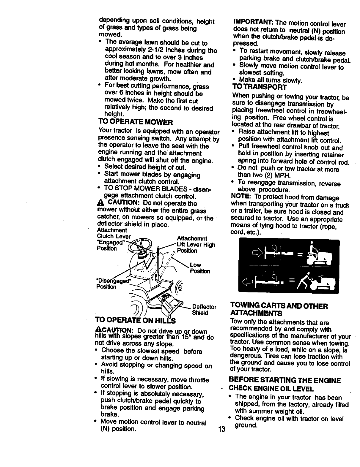
TO OPERATE MOWER
Your tractor is equipped with an operator
presence sensing switch. Any attempt by
the operator to leave the seat with the
engine running and the attachment
clutch engaged will shut off the engine.
• Select desired height of cut.
• Start mower blades by engaging
attachment dutch control.
• TO STOP MOWER BLADES - disen-
gage attachment clutch control.
A CAUTION: Do not operate the
mower without either the entire grass
catcher, on mowers so equipped, or the
deflector shield in place.
Attachment
ClutchLever Attachemnt
"Engaged"" High
Position Position
Low
Pos_on
IMPORTANT: The motion control lever
does not return to neutral (N) position
when the clutch/brake pedal is de-
pressed.
• To restart movement, slowly release
parking brake and clutch/brake pedal.
• Slowly move motion control lever to
slowest setting.
• Make all turns slowly.
TO TRANSPORT
When pushing or towing your tractor, be
sure to disengage transmission by
placing freewheel control in freewheel-
ing position. Free wheel control is
located at the rear drawbar of tractor.
• Raise attachment lift to highest
position with attachment lift control.
• Pull freewheel control knob out and
hold in position by inserting retainer
spring into forward hole of control rod.
• Do not push or tow tractor at more
than two (2) MPH.
• To reengage transmission, reverse
above procedure.
NOTE: To protect hood from damage
when transporting your tractor on a truck
or a trailer, be sure hood is closed and
secured to tractor. Use an appropdate
means of tying hood to tractor (rope,
cord, etc.).
Position
Deflector
Shield
TO OPERAT!
_CAUTION: Do not drive up or down
hills with slopes greater than 15° and do
not ddve across any slope.
• Choose the slowest speed before
starting up or down hills.
• Avoid stopping or changing speed on
hills.
• If slowing is necessary, move throttle
control lever to slower position.
• If stopping is absolutely necessary,
push clutch/brake pedal quickly to
brake position and engage parking
brake.
• Move motion control lever to neutral
(N) position.
13
TOWING CARTS AND OTHER
AI"FACHMENTS
Tow only the attachments that are
recommended by and comply with
specifications of the manufacturer of your
tractor. Use common sense when towing.
Too heavy of a load, while on a slope, is
dangerous. Tires can lose traction with
the ground and cause you to lose control
of your tractor.
BEFORE STARTING THE ENGINE
CHECK ENGINE OIL LEVEL
• The engine in your tractor has been
shipped, from the factory, already filled
with summer weight oil.
• Check engine oil with tractor on level
ground.
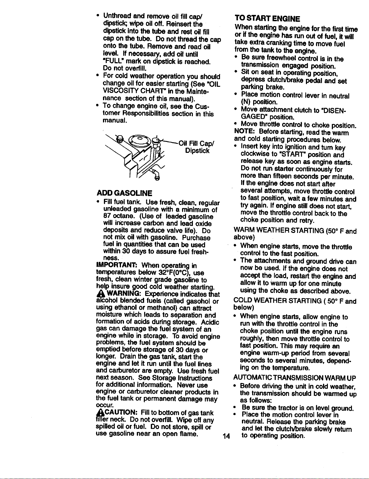
• Unthreed and remove oHfill cap/
dipstick;wipe oil off. Reinsert the
dipstick into the tube and rest oil fill
cap on the tube. Do not thread the cap
onto the tube, Remove and read oil
level. If necessary, add oil until
"FULL" mark on dipstick is reached.
Do not overfill.
• For cold weather operation you should
change oil for easier starting (See =OIL
VISCOSITY CHART" in the Mainte-
nance section of this manual).
• To change engine oil, see the Cus-
tomer Responsibilities section in this
manual.
Oil Fill Cap/
Dipstick
ADD GASOUNE
• Fill fuel tank. Use fresh, clean, regular
unleaded gasoline with a minimum of
87 octane. (Use of leaded gasoline
will increase carbon and lead oxide
deposits and reduce valve life). Do
not mix oil with gasoline. Purchase
fuel in quantities that can be used
within 30 days to assure fuel fresh-
ness.
IMPORTANT: When operating in
temperatures below 32°F(0°C), use
fresh, clean winter grade gasoline to
help insure good cold weather starting.
WARNING: Expedence indicatesthat
aTcoholblended fuels (called gasohol or
using ethanol or methanol) can attract
moisture which leads to separation and
formation of acids dudng storage. Acidic
gas can damage the fuel system of an
engine while in storage. To avoid engine
problems, the fuel system should be
emptied before storage of 30 days or
longer. Drain the gas tank, start the
engine and let it run until the fuel lines
and carburetor are empty. Use fresh fuel
next season. See Storage Instructions
for additional information. Never use
engine or carburetor cleaner products in
the fuel tank or permanent damage may
oosur.
_eCAUTION: Fillto bottom of gas tank
r neck. Do not ovedill. Wipe off any
spilled oil or fuel. Do not store, spill or
use gasoline near an open flame.
TO START ENGINE
When starting the engine forthe first time
or if the engine has run out oi fuel, it will
take extra cranking time to move fuel
from the tank to the engine.
• Be sure freewheel control is in the
transmission engaged position.
• Sit on seat in operating position,
depress clutch/brake pedal and set
parking brake.
• Place motion control lever in neutral
(N) position.
• Move attachment clutch to "DISEN-
GAGED" position.
• Move throttle control to choke position.
NOTE: Before starting, read the warm
and cold starting procedures below.
• Insert key into ignition and turn key
clockwise to "START" position and
release key as soon as engine starts.
Do not run starter continuouslyfor
more than fifteen seconds per minute.
Ifthe engine does not start after
several attempts, move throttle control
to fast position, wad a few minutes and
try again. If engine still does not start,
move the throttle control back to the
choke position and retry.
WARM WEATHER STARTING (50° F and
above)
• When engine starts, move the throttle
control to the fast position.
• The attachments and ground drive can
now be used. If the engine does not
accept the load, restart the engine and
allow it to warm up for one minute
using the choke as dascdbed above.
COLD WEATHER STARTING ( 50° F and
below)
• When engine starts, allow engine to
run with the throttle control in the
choke position untilthe engine runs
roughly, then move throttle control to
fast position. This may require an
engine warm-up pedod from several
seconds to several minutes, depend-
ing on the temperature.
AUTOMATIC TRANSMISSION WARM UP
• Before driving the unit in cold weather,
the transmission should be warmed up
as follows:
• Be sure the tractor is on level ground.
• Place the motion control lever in
neutral. Release the paddng brake
and let the clutch/brake slowly retum
14 to operating pes'_lon.

• Allow one minute for transmission to
warm up. This can be done dudng the
engine warm up period.
• The attachments can also be used
during the engine warm-up period
after the transmission has been
warmed up.
NOTE: If at a high altitude (above 3000
feet) or in cold temperatures (below 32
F) the carburetor fuel mixture may need
to be adjusted for best engine perfor-
mance. See "TO ADJUST CARBURE-
TOR" in the Service and Adjustments
section of this manual.
PURGE TRANSMISSION
4_CA.UTIO.N: Never engage or disen-
gage Treewneel lever wn.e the engine
is running.
To ensure proper operation end
performance, it is recommended that the
transmission be purged before operat-
ing tractor for the first time. This proce-
dure will remove any trapped air inside
the transmission which may have
developed during shipping of your
tractor.
IMPORTANT" Should your transmission
require removal for service or replace-
ment, it should be purged after reinstal-
lation before operating the tractor.
• Place tractor safely on level surface
with engine off and parking brake set.
• Disengage transmission by placing
freewheel control in freewheeling
position (See "TO TRANSPORT" in
this section of manual).
• Sitting in the tractor seat, start engine.
After the engine is running, move
throttle control to slow position. With
motion control lever in neutral (N)
position, slowly disengage clutcW
brake pedal.
• Move motion control lever to full
forward position and hold for five (5)
seconds. Move lever to full reverse
position and hold for five (5) seconds.
Repeat this procedure three (3) times.
NOTE: Dudng this procedure there will
be no movement of drive wheels. The air
is being removed from hydraulic drive
system.
• Move motion control lever to neutral
(N) position. Shut- off engine and set
parking brake.
• Engage transmission by placing
freewheel control in ddving position
(See "TO TRANSPORT" in this section
of manual).
• Sitting in the tractor seat, start engine.
After the engine is running, move
throttle controlto half (1/2) speed. With
motion control lever in neutral (N)
position, slowly disengage dutch/
brake pedal.
• Slowly move motion control lever
forward, after the tractor moves
approximately five (5) feet, slowly
move motion control lever to reverse
position. After the tractor moves
approximately five (5) feet return the
motion control lever to the neutral (N)
position. Repeat this procedure with
the motion control lever three (3)
times.
• Your tractor is now purged and now
ready for normal operation.
15
MOWING TIPS
• Tire chains cannot be used when the
mower housing is attached to tractor.
• Mower should be properly leveled for
best mowing performance. See "TO
LEVEL MOWER HOUSING" in the
Service and Adjustments section of
this manual.
• The left hand side of mower should be
used for trimming.
• Drive so that clippings are discharged
onto the area that has been cut. Have
the cut area to the right of the tractor.
This will result in a more even distribu-
tion of clippings and more uniform
cutting.
• When mowing large areas, start by
turning to the right so that clippings will
discharge away from shrubs, fences,
driveways, etc. After one or two
rounds, mow in the opposite direction
making left hand tums until finished.
• If grass is extremely tall, it should be
mowed twice to reduce load and
possible fire hazard from dried
clippings. Make first cut relatively
high; the second to the desired height.
• Do not mow grass when it is wet. Wet
grass will plug mower and leave
undesirable clumps. Allow grass to
dry before mowing.
• Always operate engine at full throttle
when mowing to assure better mowing
performance and proper discharge of
material. Regulate ground speed by
selecting a low enough gear to give
the mower cutting performance as well
as the quality of cut desired.
• When operating attachments, select a
ground speed that will suit the terrain
and give best performance of the
attachment being used.
MULCHING MOWING TIPS
IMPORTANT: For best performance,
keep mower housing free of built-up
grass and trash. Clean after each use.
• The special mulching blade will recut
the grass clippings many times and
reduce them in size so that as they fall
onto the lawn they will disperse into
the grass and not be noticed. Also, the
mulched grass will biodegrade quickly
to provide nutrients for the lawn.
Always mulch with your highest
engine (blade) speed as this will
provide the best rscutting action of the
blades.
• Avoid cutting your lawn when it is wet.
Wet grass tends to form clumps and
interferes with the mulching action.
The best time to mow your lawn is the
early afternoon. At this time the grass
has dried and the newly cut area will
not be exposed to the directsun.
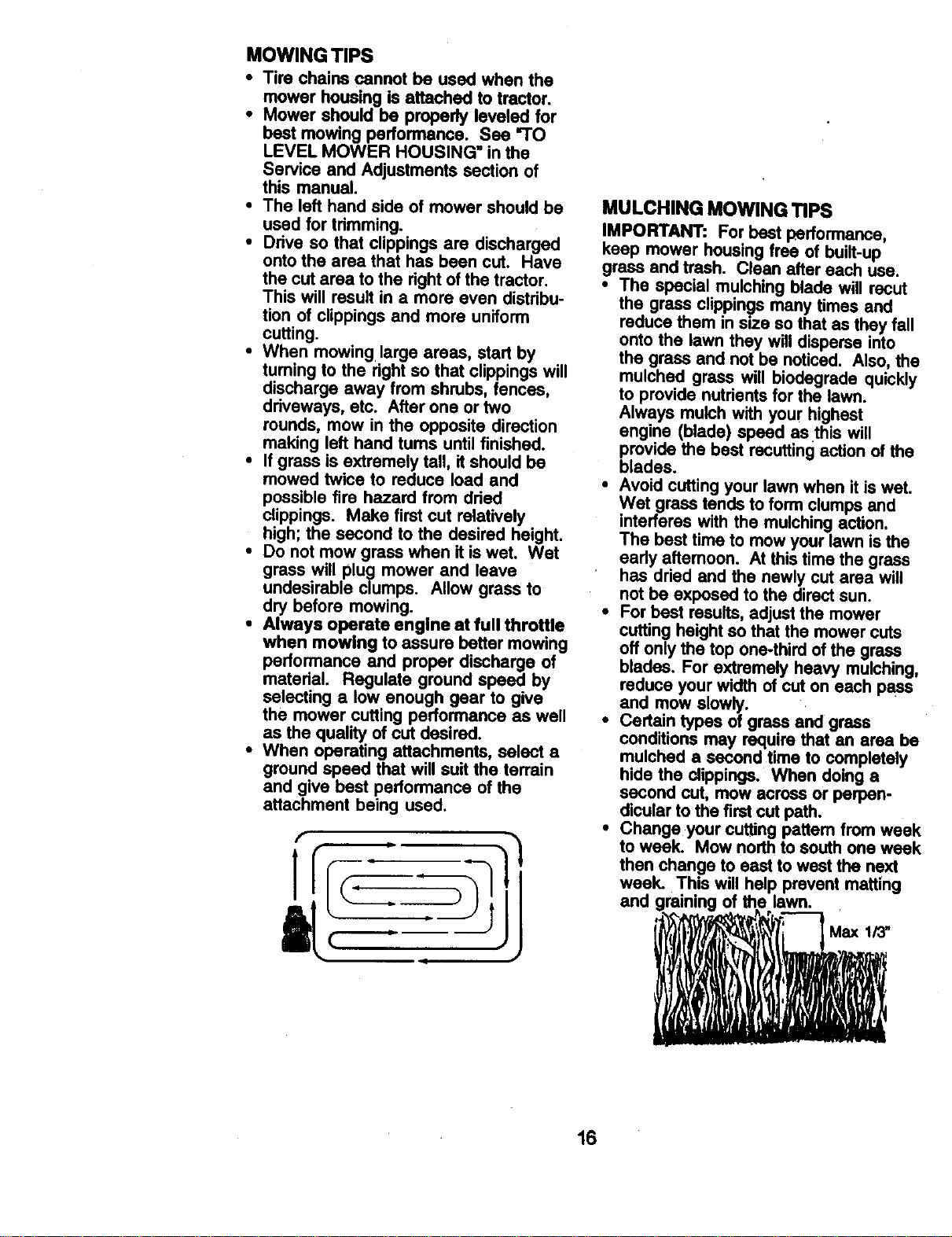
• For best results, adjust the mower
cutting heightso that the mower cuts
off only the top one-third of the grass
blades. For extremely heavy mulching,
reduce your width of cut on each pass
and mow slowly.
• Certain types of grass and grass
conditions may require that an area be
mulched a second time to completely
hide the clippings. When doing a
second cut, mow across or perpen-
dicular to the first cut path.
• Change your cuffing pattem from week
to week. Mow north to south one week
then change to east to west the next
week. This will help prevent matting
and graining of the01awn.
_"-_ Max 1/3"
16
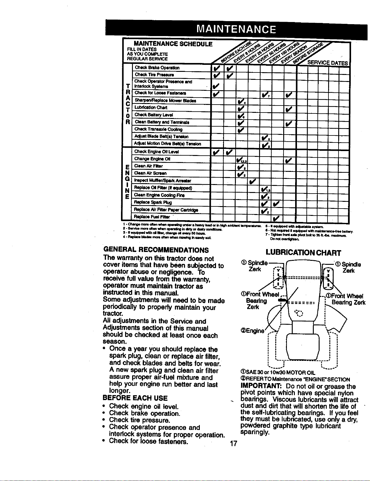
MAINTENANCE SCHEDULE
FILLiN DATES
ASYOU COMPLETE
REGULAR SERVICE
CheckBmkeOperat_n _ _
Check llm Pm_um
T Inten_ckSy_ems
T _uon C_art I/
0 c_e_ _m_ t.e_
R Ch_ck TnmsaxleCoolingCleanBattery and Tenninlds _ t_P
AdjustBladeBe_s)T_olon li/s
AdjustMotion_ Beif(s)Teflon
N _AIr_
ReplaceOil Flifer(ifaKlUipp_K0 V_I.:
NEck.ms_;neCoe_ Rm
Re_ Nr filter Pm)erC_
GENERAL RECOMMENDATIONS
The warranty on this tractor does not
cover items that have been subjected to
operator abuse or negligence. To
receive full value from the warranty,
operator must maintain tractor as
instructed in this manual.
Some adjustments will need to be made
periodically to propedy maintain your
tractor.
All adjustments in the Service and
Adjustments section of this manual
should be checked at least once each
season.
• Once a year you should replace the
spark plug, clean or replace air filter,
and check blades and belts for wear.
A new spark plug and clean air filter
assure proper air-fuel mixture and
help your engine run better and last
longer.
BEFORE EACH USE
• Check engine oil level.
• Check brake operation.
• Check tire pressure.
• Check operator presence and
interlock systems for proper operation.
• Check for loose fasteners.
LUBRICATION CHART
- _ Spindle
Zerk Zerk
•Front Wheel Whee
Bearing Bearing Ze_
Zerk
17
(DSAE 30 or 10w30 MOTOR OIL
(_)REFER TO Maintenance "ENGINE'SECTION
IMPORTANT: Do not oil or grease the
civot points which have special nylon
eadngs. Viscous lubricants will attract
dust and dirt that will shorten the life of
the self-lubdcatin_ bearings. If you feel
they must be lubncated, use only a dry,
powdered graphite type lubricant
sparingly.
TRACTOR
Always observe safety rules when
performing any maintenance.
BRAKE OPERATION
If tractor requires more than six (6) feet
stopping distance at high speed in
highest gear, than brake must be
adjusted. (See "TO ADJUST BRAKE" in
the Service and Adjustments section of
this manual).
TIRES
• Maintain proper air pressure in all tires
(See =PRODUCT SPECIFICATIONS" Rat
section of this manual). Lock
• Keep tires free of gasoline, oil, or
insect control chemicals which can
harm rubber.
• Avoid stumps; stones, deep ruts, sharp
objects and other hazards that may
cause tire damage.
NOTE: To seal tire punctures and
prevent flat tires due to slow leaks, tire
sealant may be purchased from your
local parts dealer. Tire sealant also
prevents tire dry rot and corrosion.
OPERATOR PRESENCE SYSTEM
Be sure operator presence and interlock
systems are working properly. If your
tractor does not function as described,
repair the problem immediately.
• The engine should not start unless the
clutch/brake pedal is fully depressed
and attachement clutch control is in
the disengaged position.
• When the engine is running, any
attempt by the operator to leave the
seat without first setting the parking
brake should shut off the engine.
• When the engine is running and the
attachment clutch is engaged, any
attempt by the operator to leave the
seat should shut off the engine.
• The attachment clutch should never
operate unless the operator is in the
seat.
BLADE CARE
For best results mower blades must be
kept sharp. Replace bent or damaged
blades.
BLADE REMOVAL
• Raise mower to highest pos'ition to
allow access to blades.
• Remove hex bolt, lock washer and flat
washer securing blade.
• Install new or resharpened blade with
trailing edge up towards deck as
shown. 18
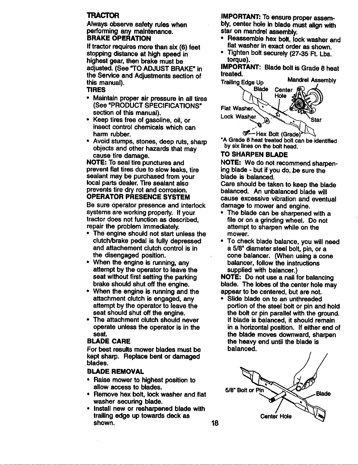
IMPORTANT: To ensure proper assem-
bly, center hole in blade must align with
star on mandrel assembly.
• Reassemble hex bolt, lock washer and
fiat washer in exact order as shown.
• Tighten bolt securely (27-35 Ft. Lbs.
torque).
IMPORTANT: Blade bolt is Grade 8 heat
treated.
Mandrel Assembly
Edge Up
Blade Center
Hole
_--- Hex Bolt
*A Grade 8 heat treated boltcan be identified
by six lines on the bolthead.
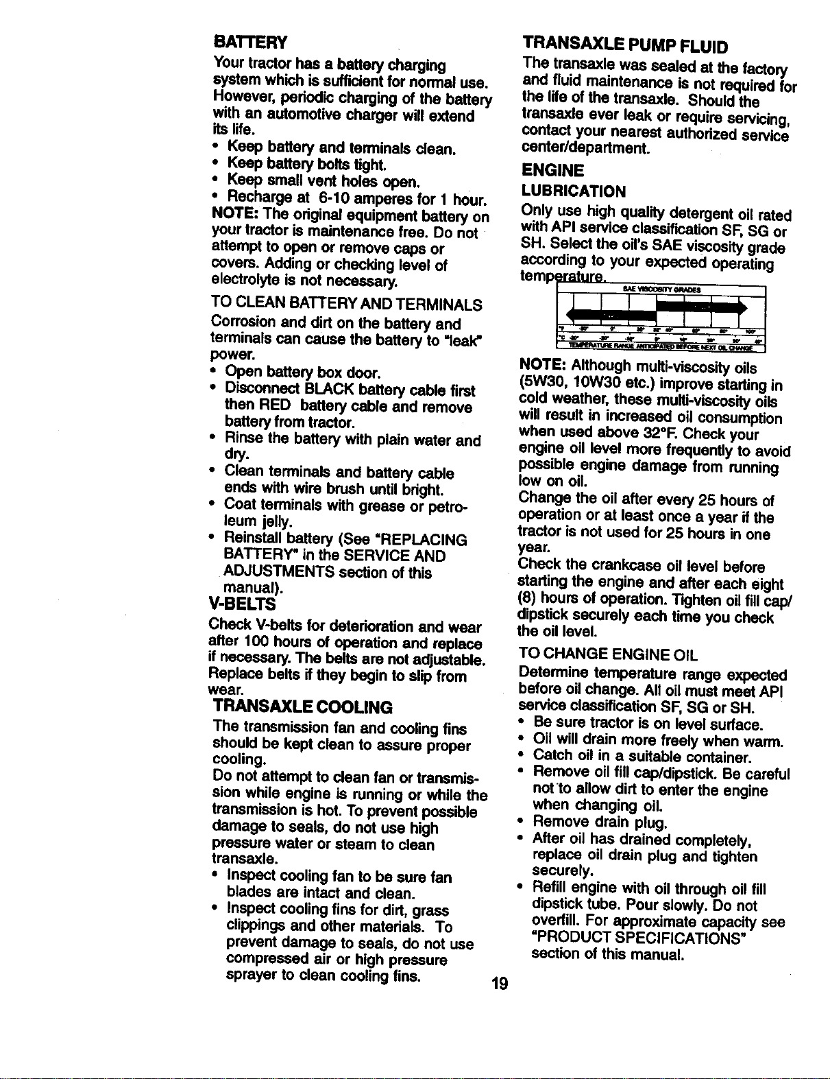
TO SHARPEN BLADE
NOTE: We do not recommend sharpen-
ing blade - but if you do, be sure the
blade is balanced.
Care should be taken to keep the blade
balanced. An unbalanced blade will
cause excessive vibration and eventual
damage to mower and engine.
• The blade can be sharpened with a
file or on a grinding wheel. Do not
attempt to sharpen while on the
mower.
• To check blade balance, you wilt need
a 5/8' diameter steel bolt, pin, or a
cone balancer. (When using a cone
balancer, follow the instructions
supplied with balancer.)
NOTE: Do not use a nail for balancing
blade. The lobes of the center hole may
appear to be centered, but are not.
• Slide blade on to an unthreaded
portion of the steel bolt or pin and hold
the bolt or pin parallel with the ground.
if blade is balanced, it should remain
in a horizontal position. If either end of
the blade moves downward, sharpen
the heavy end until the blade is
balanced.
5/8" " e
Center Hole
BATrERY
Your tractor has a battery charging
system which is sufficientfor normal use.
However, periodic charging of the battery
with an automotive charger will extend
its life.
• Keep battery and terminals clean.
• Keep battery bolts tight.
• Keep smell vent holes open.
• Recharge at 6-10 amperes for 1 hour.
NOTE: The original equipment battery on
your tractor is maintenance free. Do not
attempt to open or remove caps or
covers. Adding or checking level of
electrolyte is not necessary.
TO CLEAN BATTERY AND TERMINALS
Corrosion and dirt on the battery and
terminals can cause the battery to "leak"
power.
• Open battery box door.
• Disconnect BLACK battery cable first
then RED battery cable and remove
battery from tractor.
• Rinse the battery with plain water and
dry.
• Clean terminals and battery cable
ends with wire brush until bdght.
• Coat terminals with grease or petro-
leum jelly.
• Reinstall battery (See =REPLACING
BATTERY" in the SERVICE AND
ADJUSTMENTS section of this
manual).
V-BELTS
Check V-belts for deterioration and wear
after 100 hours of operation and replace
if necessary. The bolts are not adjustable.
Replace belts if they begin to slip from
wear.
TRANSAXLIE COOUNG
The transmission fan end cooling fins
should be kept clean to assure proper
cooling.
Do not attempt to clean fan or transmis-
sion while engine is running or while the
transmission is hot. To prevent possible
damage to seals, do not use high
pressure water or steam to clean
transexle.
• Inspect cooling fan to be sure fan
blades are intact and clean.
• Inspect cooling fins for dirt, grass
clippings and other materials. To
prevent damage to seals, do not use
compressed air or high pressure
sprayer to clean cooling fins.
TRANSAXLE PUMP FLUID
The transaxle was sealed at the factory
and fluid maintenance is not required for
the life of the transexle. Should the
transaxle ever leak or require servicing,
contact your nearest authodzed service
center/department.
ENGINE
LUBRICATION
Only use high quality detergent oil rated
with API service classification SF, SG or
SH. Select the oil's SAE viscosity grade
according to your expected operating
temperature. ,,_,==0_=_
NOTE: Although multi-viscosity oils
(5W30, 10W30 etc.) improve starting in
cold weather, these multi-viscosityoils
will result in increased oil consumption
when used above 32°F. Check your
engine oil level more frequently to avoid
possible engine damage from running
tow on oil.
Change the oil after every 25 hours of
operation or at least once a year ifthe
tractor is not used for 25 hours in one
year.
Check the crankcase oil level before
starting the engine and after each eight
(8) hours of operation. T'_hten oil fillcap/
dipstick securely each time you check
the oil level.
TO CHANGE ENGINE OIL
Determine temperature range expected
before oil change. All oil must meet API
service classification SF, SG or SH.
• Be sure tractor is on level surface.
• Oil will drain more freely when warm.
• Catch oil in a suitable container.
• Remove oil fill cap/dipstick. Be careful
not to allow dirt to enter the engine
when changing oil.
• Remove drain plug.
• After oil has drained completely,
replace oil drain plug and tighten
securely.
• Refill engine with oil through oil fill
dipstick tube. Pour slowly. Do not
overfill. For approximate capacity see
=PRODUCT SPECIFICATIONS"
section of this manual.
t9
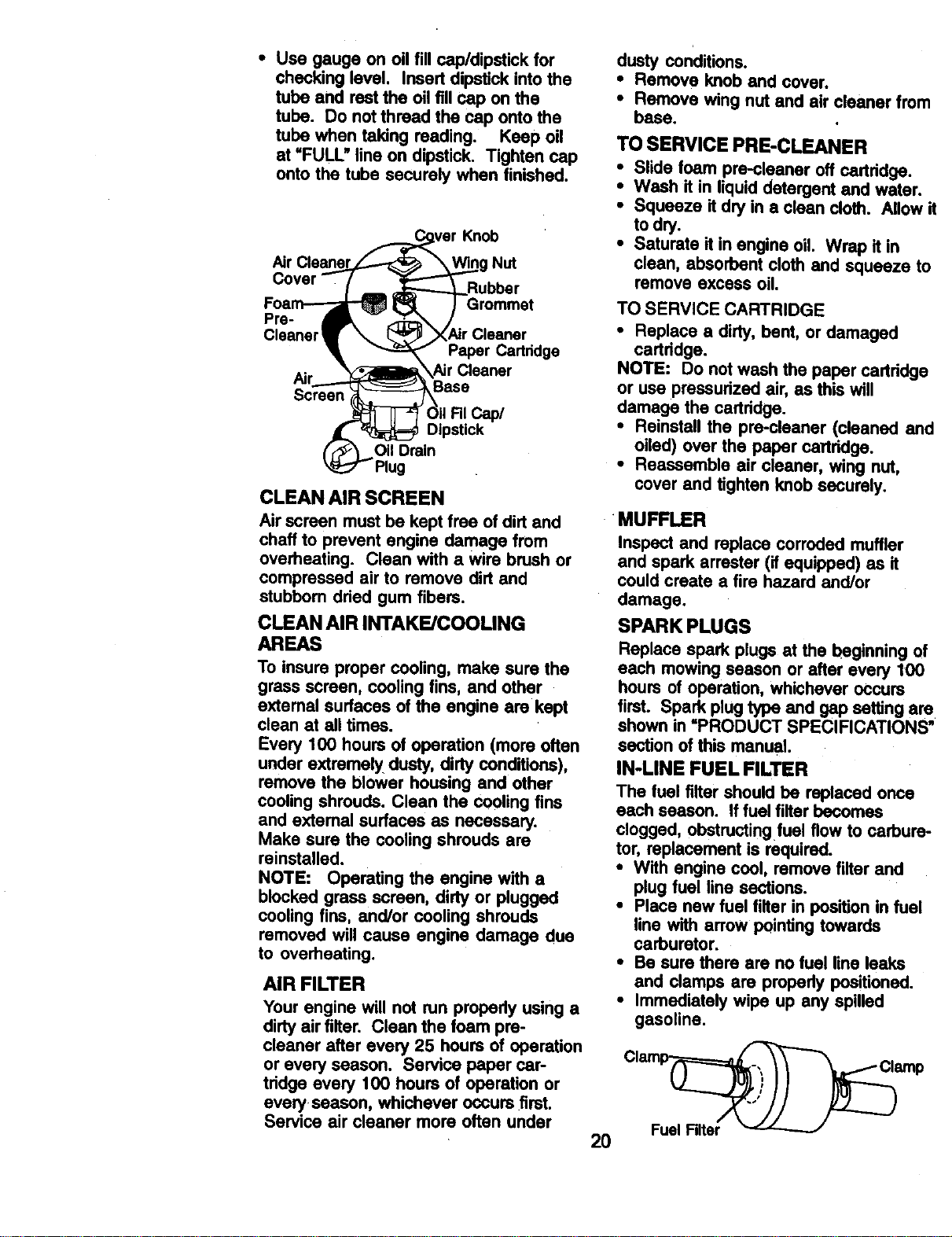
• Use gauge on oil fill cap/dipstick for
checking level. Insert dipstick into the
tube and rest the oil fill cap on the
tube. Do not thread the cap onto the
tube when taking reading. Keep oil
at =FULL" line on dipstick. Tighten cap
onto the tube securely when finished.
( _ver Knob
Air Cleaner_j ___0g Nut
Cover --- ( _,= _ ..___gubber
Foa_ _ )Grommet
Pre- _ - lr_
Cleaner_[ _ XAir Cleaner
Paper Cartridge
_c" _ XAirCleaner
r_ _ kBase
rean
,d /\
o,pstlck
(F_ Oil Drain
Plug
CLEAN AIR SCREEN
Air screen must be kept free of dirt and
chaff to prevent engine damage from
overheating. Clean with a wire brush or
compressed air to remove dirt and
stubborn dried gum fibers.
CLEAN AIR INTAKE/COOLING
AREAS
To insure proper cooling, make sure the
grass screen, cooling fins, and other
external surfaces of the engine are kept
clean at all times.
Every 100 hours of operation (more often
under extremely dusty, dirty conditions),
remove the blower housing and other
cooling shrouds. Clean the cooling fins
and axtemal surfaces as necessary.
Make sure the cooling shrouds are
reinstalled.
NOTE: Operating the engine with a
blocked grass screen, dirty or plugged
cooling fins, and/or cooling shrouds
removed will cause engine damage due
to overheating.
AIR FILTER
Your engine will not run propedy using a
dirty air filter. Clean the foam pre-
cleaner after every 25 hours of operation
or every season. Service paper car-
tridge every 100 hours of operation or
every season, whichever occurs first.
Service air cleaner more often under
dusty conditions.
• Remove knob and cover.
• Remove wing nut and air cleaner from
base.
TO SERVICE PRE-CLEANER
• Slide foam pre-cleaner off oartddge.
• Wash it in liquid detergent and water.
• Squeeze itdry in a clean cloth. Allow it
to dry.
• Saturate it in engine oil. Wrap it in
clean, absorbent cloth and squeeze to
remove excess oil.
TO SERVICE CARTRIDGE
• Replace a dirty, bent, or damaged
cartddge.
NOTE: Do not wash the paper cartridge
or use pressurized air, as this will
damage the cartridge.
• Reinstall the pre-cleaner (cleaned and
oiled) over the paper cartridge.
• Reassemble air cleaner, wing nut,
cover and tighten knob securely.
•MUFFLER
2O
Inspect and replace corroded muffler
and spark arrester (if equipped) as it
could create a fire hazard and/or
damage.
SPARK PLUGS
Replace spark plugs at the beginning of
each mowing season or after every 100
hours of operation, whichever occurs
first. Spark plug type and gap setting are
shown in =PRODUCT SPECIFICATIONS"
section of this manual
IN-LINE FUEL FILTER
The fuel filter should be replaced once
each season. Iffuel filter becomes
clogged, obstruotingfuel flow to carbure-
tor, replacement is required.
• With engine cool, remove filter and
plug fuel line sections.
• Place new fuel filter in position in fuel
line with arrow pointing towards
carburetor.
• Be sure there are no fuel line leaks
and clamps are properly positioned.
• Immediately wipe up any spilled
gasoline.
CI_ amp
Fuai Filter
CLEANING
i lean engine, battery, seat, finish, etc.
of all foreign matter.
Keep finished sudaoss and wheels
free of all Qesoline, oil, etc.
Protect painted surfaces with automo-
tire type wax.
We do not recommend using a garden
hose to clean your tractor unless the
electrical system, muffler,air filter and
carburetor are covered to keep water oL
Water in engine can result in a shod-
ened engine life.
i i
_kCAUTION: Before performing any service or adjustments:
* Depress clutch/brake pedal tully and set parking brake.
Place gearshift lever in neutral (N)position;,
• Place attachment clutch in "DISENGAGED position.
i Tum ignitionkey "OFF" and remove key.
Make sure the blades and all moving parts have completely stopped.
Discon.nectspark plug wire from spark plug and place wire where itcannot
come in contact with plug.
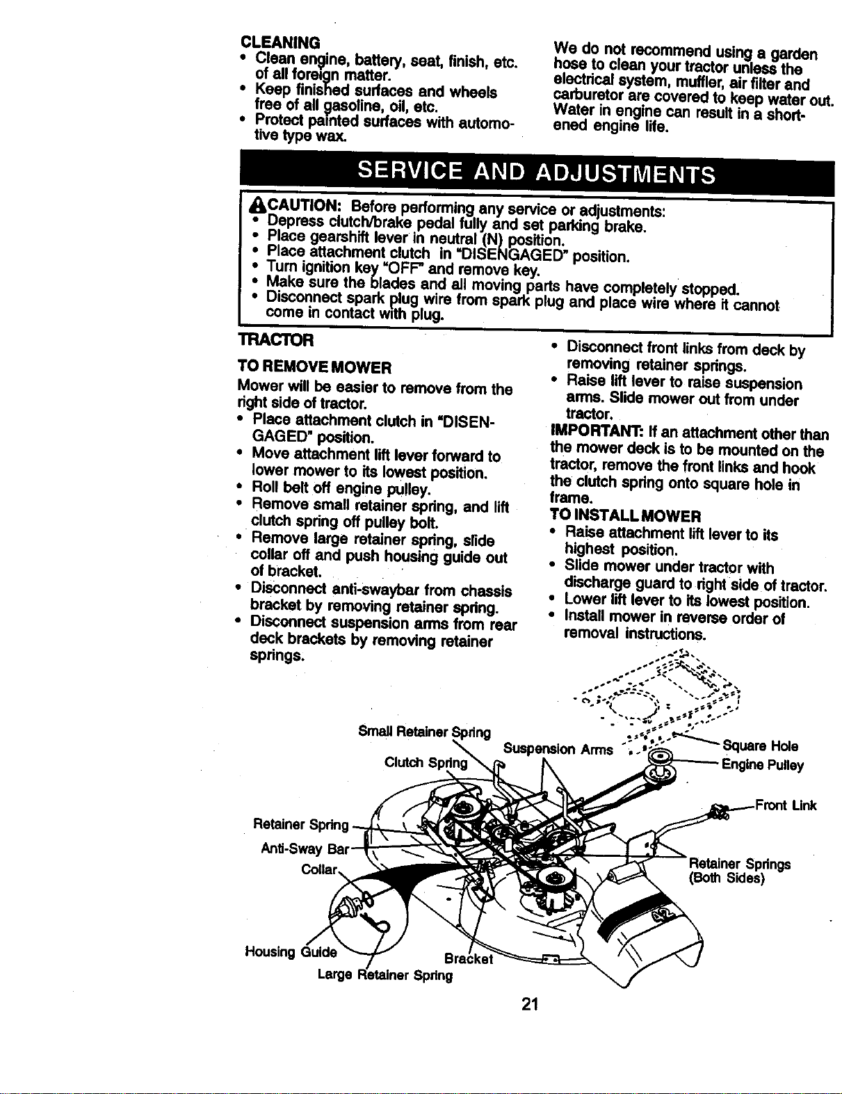
TRACI'OR
TO REMOVE MOWER
Mower will be easier to remove from the
dght side of tractor.
• Place attachment clutch in "DISEN-
GAGED" position.
• Move attachment liftlever forward to
lower mower to its lowest position.
• Roll belt off engine PUlley.
• Remove small retainer spdng, and lift
clutch spdng off pulley bolt.
• Remove large retainer spdng, slide
collar off and push housing guide out
of bracket.
• Disconnect anfi-swaybar from chassis
bracket by removing retainer spdng.
• Disconnect suspension arms from rear
deck brackets by removing retainer
springs,
• Disconnect front links from deck by
removing retainer springs.
• Raise liftlever to raise suspension
arms. Slide mower out from under
tractor.
IMPORTANT: If an attachment other that
the mower deck is to be mounted on the
tractor, remove the front links and hook
the clutch spdng onto square hole in
frame.
TO INSTALL MOWER
• Raise attachment liftlever to its
highest position.
• Slide mower under tractor with
discharge guard to dghtside of tractol
• Lower liftlever to its lowest position.
• Install mower in reverse order of
removal instructions.
Small Retainer Spdng
Retainer
AnU-Swa'
Link
Springs
(BothSides)
Housing Guide
I.srg,
21
TO LEVEL MOWER HOUSING •
Adjust the mower while tractor is parked
on level ground or ddveway. Make sure
tiros aroproperly inflated (See "PROD-
UCT SPECIFICATIONS" section of this •
manual). Iftires are over or
undednflated, you will not properly •
adjust your mower.
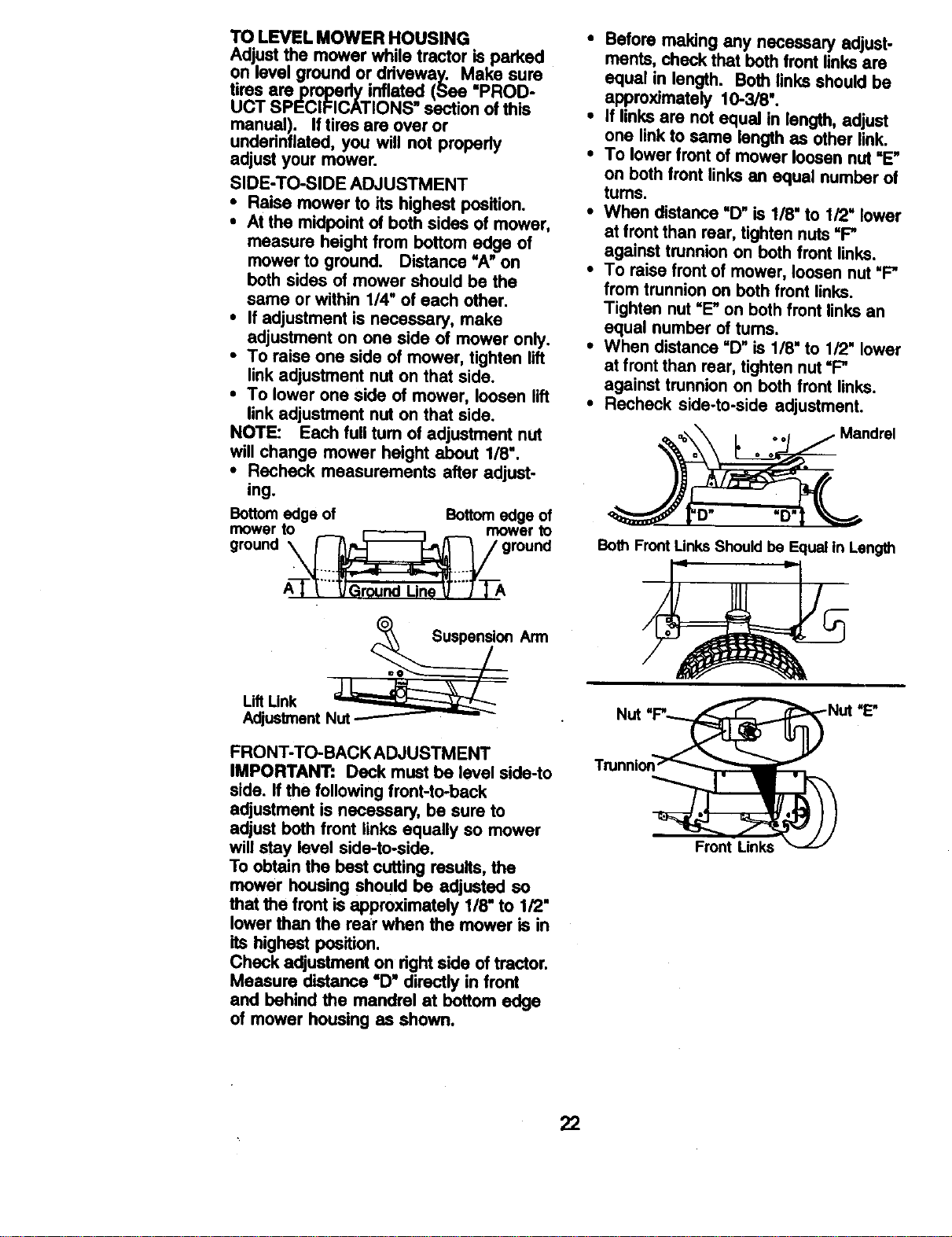
SIDE-TO-SIDE ADJUSTMENT
• Raise mower to its highest position.
• At the midpoint of both sides of mower,
measure height from bottom edge of
mower to ground. Distance "A"on •
both sides of mower should be the
same orwithin 1/4" of each other.
• If adjustment is necessary, make
adjustment on one side of mower only. .
• To raise one side of mower, tighten lift
link adjustment nut on that side.
• To lower one side of mower, loosen lift .
link adjustment nut on that side.
NOTE: Each full turn of adjustment nut
will change mower height about 118".
• Recheck measurements after adjust-
ing.
Bottomedgeof Bottomedge of
gmOou,ne_ t_.___ gmo_c_n_
Arm
LiftLink "==a_--_;;;;_ll_
AdjustmentNut
FRONT-TO-BACK ADJUSTMENT
IMPORTANT: Deck must be level side-to
side. If the following front-to-beck
a_ustment is necessary, be sure to
adjust both front links equally so mower
will stay level side-to-side.
To obtain the best cutting results, the
mower housing should be adjusted so
that the front isapproximately 1/8" to 1/2"
lower than the rear when the mower is in
its highest position.
Check adjustment on rightside of tractor.
Measure distance "D" directly in front
and behind the mandrel at bottom edge
of mower housing as shown.
Before making any necessary adjust-
ments, check that both front links are
equal in length. Both links should be
approximately 10-3/8".
If links are not equal In length, adjust
one link to same length as other link.
To lower front of mower loosen nut =E"
on both front links an equal number of
tums.
When distance "D" is 118' to 1/2" lower
at front than roar, tighten nuts"P
against trunnion on both front links.
To raise front of mower, loosen nut "F"
from trunnion on both front links.
Tighten nut "E" on both front links an
equal number of tums.
When distance "D" is 1/8" to 1/2" lower
at front than rear, tighten nut "F"
against trunnion on both front links.
Recheck side-to-side adjustment.
'D" "D"
Both Front Links Should be Equal In Length
22

TO REPLACE MOWER BLADE
DRIVE BELT
The mower blade drive belt may be
replaced without tools. Park the tractor
on level surface. Engage parking brake.
BELT REMOVAL-
• Remove mower from tractor (See "TO
REMOVE MOWER" in this section of
this manual).
• Work belt off both mandrel pulleys and
idler pulleys.
• Pull belt away from mower.
BELT INSTALLATION -
• Install new belt in reverse order of
removal.
• Make sure belt is in all pulley grooves
and inside all belt guides.
• Install mower in reverse order of
removal instructions.
Mandrel
Pulley
TO ADJUST BRAKE
Your tractor is equipped with an adjust-
able brake system which is mounted on
the side of the transaxle.
Iftractor requires more than six (6) feet
stopping distance at hlgh speed in
highest gear, then brake must be
adjusted.
• Depress clutch/brake pedal and
engage parking brake.
• Measure distance between brake
operating arm and nut "A" on brake
rod.
• If distance is other than 1-9/16", loosen
jam nut and turn nut "A"until distance
becomes 1-9/16". Retightan jam nut
against nut "A'.
• Road test tractor for proper stopping
distance as stated above. Readjust if
necessary. If stopping distance is still
greater than six (6) feet in highest
gear, fudher maintenance is necee-
sary. Contact your nearest authorized
service center/depertment.
W'_h Parking Brake 'Engaged"
Nut "A"
Jam Nut
Do Not touch thisnut. If furlher brake
adjustmentis necessarycontactyour
nearestauthorized servicecenter/
department
TO REPLACE MOTION DRIVE BELT
Park the tractor on level surface. En-
gage parking brake. For assistance,
there is a belt installation guide decal on
bottom side of left footrest.
• Remove mower (See =1"OREMOVE
MOWER" in this section of this
manual.)
• Remove belt from stationary idler and
clutching idler.
• Pull belt slack toward rear of tractor.
Carefully remove belt upwards from
transmission input pulley and over
cooling fan blades.
• Pull belt toward front of tractor and
remove downward from around
engine pulley.
• Install new belt by reversing above
procedure.
"u"0'en;-----
o,utch,n ld,er--
Input Pulley\ _
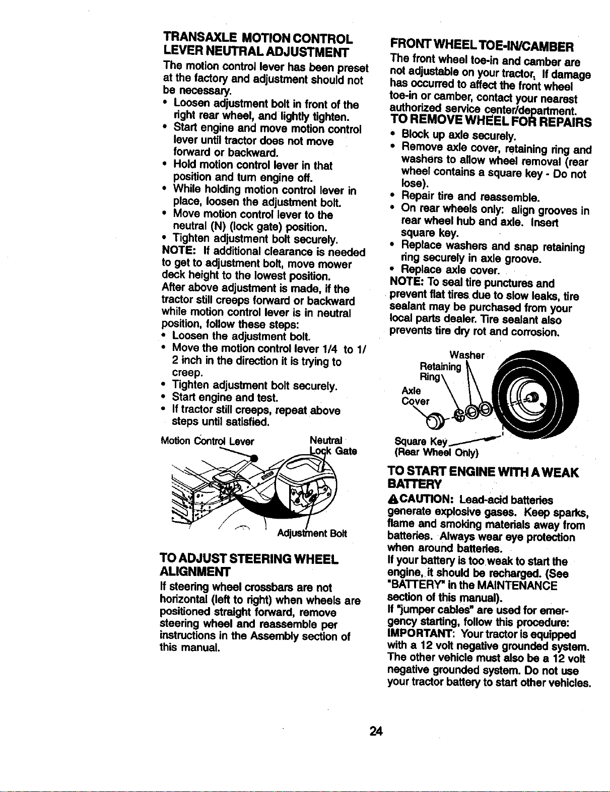
TRANSAXLE MOTION CONTROL
LEVER NEUTRAL ADJUSTMENT
The motion control lever has been preset
at the factory and adjustment should not
be necessary.
• Loosen adjustment bolt in front of the
dght rear wheel, and lightly tighten.
• Stad engine and move motion control
lever until tractor does not move
forward or backward.
• Hold motion control lever in that
position and tum engine off.
• While holding motion control lever in
place, loosen the adjustment bolt.
• Move motion control lever to the
neutral (N) (lock gate) position.
• Tighten adjustment bolt securely.
NOTE: If additional clearance is needed
to get to adjustment bolt, move mower
deck height to the lowest position.
After above adjustment is made, if the
tractor still creeps forward or backward
while motion control lever is in neutral
position, follow these steps:
• Loosen the adjustment bolt.
• Move the motion control lever 1/4 to 1/
2 inch in the direction it is trying to
creep.
• Tighten adjustment bolt securely.
• Start engine and test.
• Iftractor still creeps, repeat above
steps until satisfied.
Mo_onContro4Lever
Neutral
Gate
TO ADJUST STEERING WHEEL
ALIGNMENT
If steering wheel crossbars are not
horizontal (left to right) when wheels are
positioned straight forward, remove
steering wheel and reassemble per
instructionsin the Assembly section of
this manual.
FRONT WHEEL TOE-IN/CAMBER
The front wheel toe-in and camber are
not adjustable on your tractor, If damage
has occurred to affect the front wheel
toe-in or camber, contact your nearest
authorized service center/depadment.
TO REMOVE WHEEL FOR REPAIRS
• Block up axle securely.
• Remove axle cover, retaining ring and
washers to allow wheel removal (rear
wheel contains a square key - Do not
lose).
• Repair tire and reassemble.
• On rear wheels only: align grooves in
rear wheel hub and axle. Insert
square key.
• Replace washers and snap retaining
ring securely in axle groove.
• Replace axle cover.
NOTE: To seal tire punctures and
prevent flat tires due to slow leaks, tire
sealant may be purchased from your
local parts dealer. Tire sealant also
prevents tire dry rot and corrosion.
J"\ r- 'l
SquareKey/
(RearWhe_ Orgy)
TO START ENGINE WITH AWEAK
BA'n'ERY
ACAUTION: Lead-acid baftedes
generate explosive gases. Keep sparks,
flame and smoking matedais away from
batteries. Always wear eye protection
when around batteries.
Ifyour battery istooweak to start the
engine, it should be recharged, (See
"BATI'ERY" inthe MAINTENANCE
section of this manual).
if "jumper cables" are used for emer-
gency stading, follow this procedure:
IMPORTANT: Yourtractor is equipped
with a 12 volt negative grounded system.
The other vehicle must also be a 12 volt
negative grounded system. Do not use
your tractor battery to start other vehicles.
24
TO ATTACH JUMPER CABLES -
• Connect each end of the RED cable to
the POSITIVE (+) terminal of each
battery, taking care not to short against
chassis.
• Connect one end of the BLACK cable
to the NEGATIVE (-) terminal of fully
charged battery.
• Connect the other end of the BLACK
cable to good CHASSIS GROUND,
away from fuel tank and battery.
TO REMOVE CABLES, REVERSE
ORDER -
• BLACK cable first from chassis and
then from the fully charged battery.
• RED cable last from both batterias.
PositiveTerminal Negative Terminal
Battery
PositiveTerminal
Negative Terminal
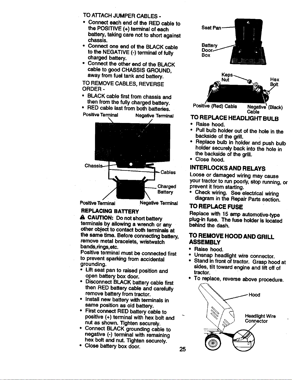
REPLACING BATTERY
A CAUTION: Do notshort battery
terminals by allowing a wrench Or any
other object to contact both terminals at
the same time. Before connecting battery,
remove metal bracelets, wristwatch
bands,rings,etc.
Positive terminal must be connected first
to prevent sparking from accidental
grounding.
* Lift seat pan to raised position and
open battery box door.
. Disconnect BLACK battery cable first
then RED battery cable and carefully
remove battery from tractor.
* Install new battery with terminals in
same position as old battery.
, First connect RED battery cable to
positive (+) terminal with hex bolt and
nut as shown. Tighten securely.
• Connect BLACK grounding cable to
negative (-) terminal with remaining
hex bolt and nut. Tighten securely.
• Close battery box door.
Seat
Nut Hex
(Red) Cable Black)
TO REPLACE HEADLIGHT BULB
• Raise hood.
• Pull bulb holder out of the hole in the
backside of the gdlL
• Replace bulb in holder and push bulb
holder securely back Into the hole in
the backside of the grill.
• Close hood.
INTERLOCKS AND RELAYS
Loose or damaged wiring may cause
your tractor to run poorly,stop running, or
prevent it from starting.
• Check wiring. See electrical wiring
diagram in the Repair Parts section.
TO REPLACE FUSE
Replace with 15 amp automotive-type
plug-in fuse. The fuse holder Is located
behind the dash.
TO REMOVE HOOD AND GRILL
ASSEMBLY
. Raise hood.
• Unsnap headlight wire connector.
• Stand in front of tractor. Grasp hood at
sides, tilttoward engine and lift off of
tractor.
* To replace, reverse above procedure.
_e_dli:ht Wire
25 _ector
Maintenance, repair, or replacement of
the emission control devices and
systems, which are being done at the
customers expense, may be performed
by any non.road engine repair establish-
ment or individual. Warranty repairs must
be performed by an authodzed engine
manufacturer's service outlet.
ENGINE
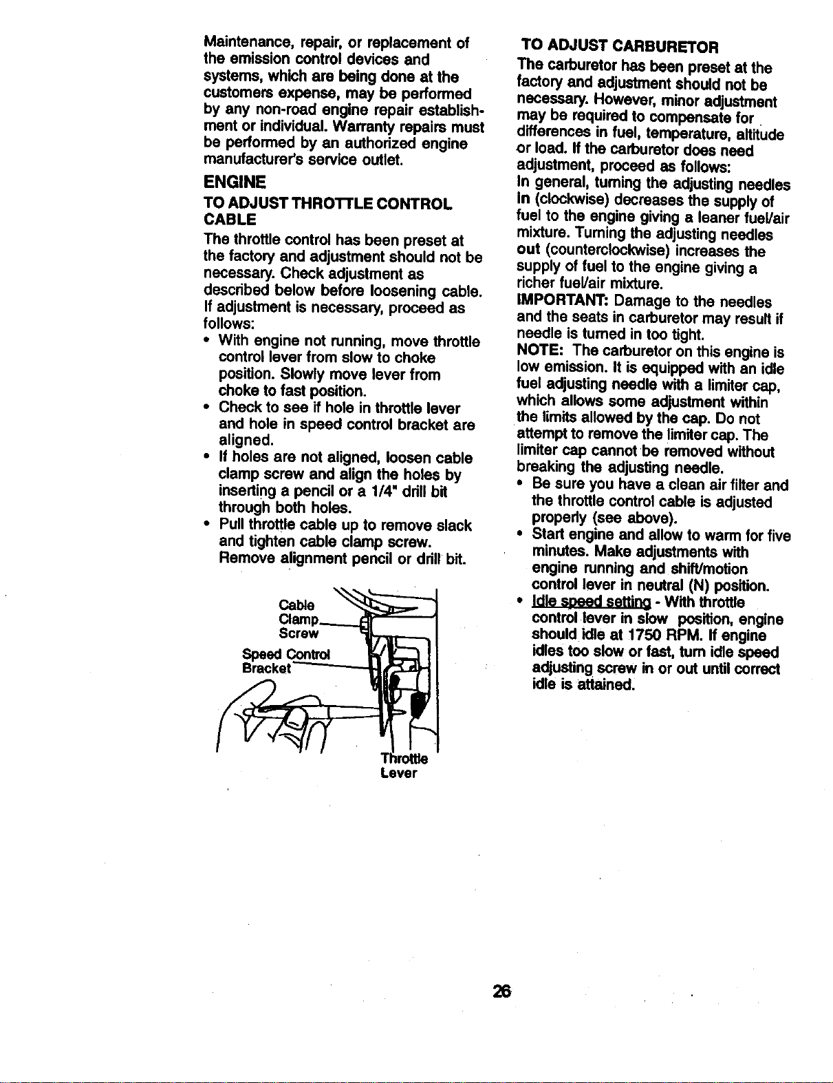
TO ADJUST THROTI'LE CONTROL
CABLE
The throttle control has been preset at
the factory and adjustment should not be
necessary. Check adjustment as
descdbed below before loosening cable.
If adjustment is necessary, proceed as
follows:
= With engine not running, move throttle
control lever from slow to choke
position. Slowly move lever from
choke to fast position.
• Check to see if hole in throttle lever
and hole in speed control bracket are
aligned.
• If holes are not aligned, loosen cable
clamp screw and align the holes by
inserting a pencil or a 1/4" ddll bit
through both holes.
• Pull throttle cable up to remove slack
and tighten cable clamp screw.
Remove alignment pencil or ddll bit.
Cable
Screw
SpeedControl
Bracket
TO ADJUST CARBURETOR
The carburetor has been preset at the
factory and adjustment should not be
necessary. However, minor adjustment
may be required to compensate for
differences in fuel, temperature, altitude
or load. If the carburetor does need
adjustment, proceed as follows:
In general, tuming the adjusting needles
In (clockwise) decreases the supply of
fuel to the engine giving a leaner fuel/air
mixture. Tuming the adjusting needles
out (counterclockwise) increases the
supply of fuel to the engine giving a
richer fuel/air mixture.
IMPORTANT: Damage to the needles
and the seats in carburetor may resultif
needle isturned in too tight.
NOTE: The carburetor on this engine is
low emission. It is equipped with an idle
fuel adjusting needle with a limiter cap,
which allows some adjustment within
the limitsallowed by the cap. Do not
attempt to remove the limitercap. The
limiter cap cannot be removed without
breaking the adjusting needle.
• Be sure you have a clean air filter and
the throttle control cable is adjusted
properly (see above).
• Start engine and allow to warm for five
minutes. Make adjustments with
engine running and shift/motion
control lever in neutral (N) position.
• J._ - With throttle
control lever in slew position, engine
should idle at 1750 RPM. If engine
idles too slow or fast, tum idle speed
adjustingscrew in or out until correct
idle is attained:
TI _ro_
Lever
26
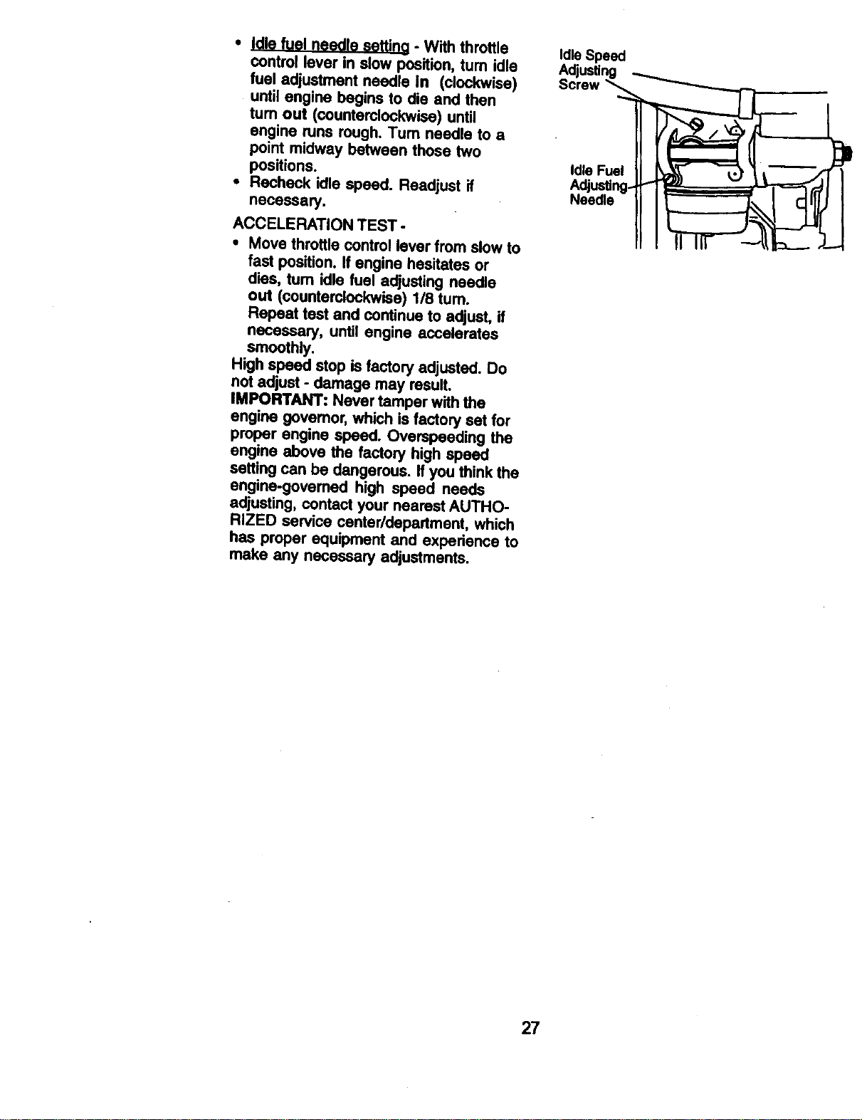
• Idle fuel needle settina - With throttle
control lever in slow position, tum idle
fuel adjustment needle in (clockwise)
until engine begins to die and then
tum out (counterclockwise) until
engine runs rough. Turn needle to a
point midway between those two
positions.
• Recheck idle speed. Readjust if
necessary.
ACCELERATION TEST -
• Move throttle control lever from slow to
fast pos'diono If engine hesitates or
dies, turn idle fuel adjusting needle
out (counterclockwise) 1/8 turn.
Repeat test and continue to adjust, if
necessary, until engine accelerates
smoothly.
High speed stop is factory adjusted. Do
not adjust - damage may result.
IMPORTANT: Never tamper with the
engine governor,which is factory set for
proper engine speed. Overspeeding the
engine above the factory high speed
setting can be dangerous. If you think the
engine-governed high speed needs
adjusting, contact your nearest AUTHO-
RIZED service center/department, which
has proper equipment and experience to
make any necessary adjustments.
IdleSpeed
Adjusting
Screw _
27
immediately prepare your tractor for
storage at the end of the season or ifthe
tractor will not be used for 30 days or
more.
_. CAUTION: Neverstore the tractor
with _asoline in the tank inside a
building where fumes may reach an
open flame or spark. Allow the engine to
cool before storing in any enclosure.
TRACTOR
Remove mower from tractor for winter
storage. When mower is to be stored for
a penod of time, clean it thoroughly,
remove all did, grease, leaves, etc. Store
in a clean, dry area.
• Clean entire tractor (See "CLEANING"
in the Maintenance section of this
manual).
• Inspect and replace belts, if necessary
(See belt replacement instructionsin
the Service and Adjustments section of
this manual).
• Lubricate as shown in the Mainte-
nance section of this manual.
• Be sure that all nuts, bolts and screws
are securely fastened. Inspect moving
pads for damage, breakage and wear.
Replace if necessary.
• Touch up all rusted or chipped paint
surfaces; sand lightly before painting.
BATFERY
Fully charge the battery for storage.
After a period of Ume in storage,
battery may require recharging.
• To help prevent corrosion and power
leakage dudng long periods of
storage, battery cables should be
disconnected and battery cleaned
thoroughly (see =TO CLEAN BATTERY
AND TERMINALS" in the Maintenance
section of this manual).
• Af_ercleaning, leave cables discon-
nected and place cables where they
cannot come in contact with battery
terminals.
• Ifbattery is removed from tractor for
storage, do not store battery directly on
concrete or damp surfaces.
ENGtNE
FUELSYSTEM
IMPORTANT: Itis important to prevent
gum deposits from forming in essential
fuel system parts such as carburetor, fuel
filter,fuel hose, or tank during storage.
Also, experience indicates that alcohol
blended fuels 9called gasohol or using
ethanol or methanol) can attract moisture
which leads to separation and formation
of acids during storage. Acidic gas can
dema_e the fuel system of an engine
while Jnstorage.
• Drain the fuel tank.
• Start the engine and let it run until the
fuel lines and carburetor are empty.
• Never use engine or (_arburetor
cleaner products in the fuel tank or
permanent damage may occur.
• Use fresh fuel next season.
NOTE: Fuel stabilizer is an acceptable
altemative in minimizing the formation of
fuel gum deposits during storage. Add
stabilizer to gasoline infuel tank or
storage container. Always follow the mix
ratio found on stabilizer container. Run
engine at least 10 minutesafter adding
stabilizer to allow the stabilizer to reach
the carburetor. Do not drain the gas tank
and carburetor if using fuel stabilizer.
ENGINE OIL
Drain oil (with engine warm) and replace
with clean engine oil. (See =ENGINE" in
the Maintenance section of this manual).
CYLINDER(S)
• Remove spark plug(s).
• Pour one ounce of oil through spark
plug hole(s) into cylinder(s).
• Tum ignitionkey to =START" position
for a few seconds to distributeoil.
• Replace with new spark p!ug(s).
OTHER
• DOnot store gasoline from one season
to another.
• Replace your gasoline can if your can
starts to rust. Rustand/or dirt inyour
gasoline will cause problems.
• If possible, store your tractor indoors
and cover it to give protection from
dust and dirt.
• Cover your tractor with a suitable
protective cover that does not retain
moisture. Do not use plastic. Plastic
cannot breathe which allows conden-
sation to form and willcause your
tractor to rust.
IMPORTANT: Never cover tractor while
engine and exhaust areas are still
warm.
28
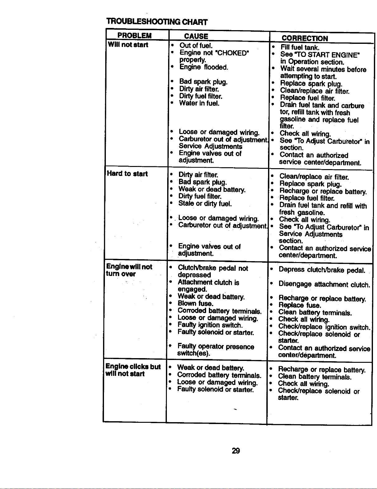
TROUBLESHOOTING CHART
PROBLEM CAUSE CORRECTION
Will not start
Hard to start
Engine will not
turn over
Engine clicks but
wig not start
• _ off_I.
• Engine not "CHOKED"
propedy.
• Engine flooded.
• Bad spark plug.
• Dirty airfilter.
• Dirty fuel filter.
• Water in fuel.
• Loose or damaged wiring.
• Carburetor out of adjustment
Service Adjustments
• Engine valves out of
adjustment.
Dirty airfilter.
i•
I. Badsparkplug.
• Weak or dead battery.
• Dirty fuel filter.
• Stale or dirtyfuel.
• Loose or damaged wiring.
• Carburetor out of adjustment
• Engine valves out of
adjustment.
• Clutch/orake pedal not
depressed
• Attachment clutch is
engaged.
i eak or dead battery.
Blown fuse.
Corroded battery terminals.
Loose or damaged wiflng.
• Faulty ignition switch.
• Faulty soler_d or starter.
t
Faulty operator presence
switch(as).
• Weak or dead battery.
• Fill fuel tank.
• See "TO START ENGINE"
in Operation section.
• Wait several minutes before
attempting to stad.
• Replace spark plug.
• Clean/rsplace air filter.
• Replace fuel filter.
• Drain fuel tank and carbure
tot, refill tank withfresh
gasoline and replace fuel
filter.
• Check all wiring.
• See "To Adjust Carburetor" ir
section.
Contact an authorized
service centerldepartment.
• Clean/replace air filter.
• Replace spark plug.
• Recharge or replace battery.
• Replace fuel filter.
• Drain fuel tank and refill with
fresh gasoline.
• Check all wiring.
• See "To Adjust Carburetor" in
Service Adjustments
section.
• Contact an authorized serv_
center/department.
• Depress clutch/brake pedal.
• Disengage attachment clutch,
• Recharge or replace battery.
• Replace fuse.
• Clean battery terminals.
• Check all wiring.
• Chack/mplace ignition switch
• Check/replace solenoid or
starter.
• Contact en authorized eervic_
center/department.
i•
Corroded battery terminals.
I. Loose or damaged widng.
• Faulty solenoid or starter.
I. Recharge or replace battery.
• Clean battery terminals.
• Check all widng.
• Check/replace solenoid or
starter.
29
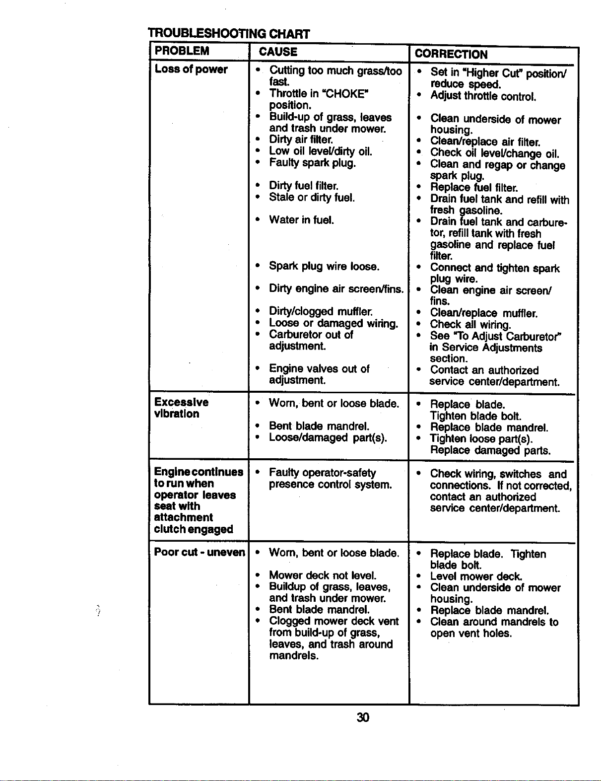
TROUBLESHOO_NG CHART
PROBLEM CAUSE
CORRECTION
Lossofpower •
Excessive
vibration
Cutting too much grass/too
fast.
Throttle in =CHOKE"
position.
Build-up of grass, leaves
and trash under mower.
• Dirty air filter.
• Low oil level/dirty oil.
• Faulty spark plug.
• Dirty fuel filter.
• Stale or dirty fuel.
Engine continues
to run when
operator leaves
seat with
attachment
clutch engaged
Poor cut - uneven
• Water in fuel.
• Spark plug wire loose.
• Dirty engine air screen/fins.
• Dirty/clogged muffler:
• Loose or damaged wiring.
• Carburetor out of
adjustment.
• Engine valves out of
adjustment.
•Wom, bent or loose blade.
• Bent blade mandrel.
• Loose/damaged part(s).
• Faulty operator-safety
presence control system.
Wom, bent or loose blade.
Mower deck not level.
Buildup of grass, leaves,
and trash under mower.
Bent blade mandrel.
Clogged mower deck vent
from build-up of grass,
leaves, and trash around
mandrels.
• Set in =Higher Cut" position/
reduce speed.
• Adjust throttle control.
• Clean underside of mower
housing.
• Clean/replace air filter.
• Check oil level/change oil.
• Clean and rogap or change
spark plug.
• Replace fuel filter.
• Drain fuel tank and refill with
fresh gasoline.
• Drain fuel tank and carbure-
tor, refill tank with fresh
gasoline and replace fuel
filter.
• Connect and tighten spark
plug wire.
• Clean engine air screen/
fins.
• Clean/replace muffler.
• Check all wiring.
• See "To Adjust Carburetor"
in Service Adjustments
section.
• Contact an authodzed
service center/department.
• Replace blade.
Tighten blade bolt.
• Replace blade mandrel.
• Tighten loose part(s).
Replace damaged parts.
Check wiring, switches and
connections. If not corrected,
contact an authorized
service center/department.
• Replace blade. Tighten
blade bolt.
• Level mower deck.
• Clean underside of mower
housing.
• Replace blade mandrel.
• Clean around mandrels to
open vent holes.
30
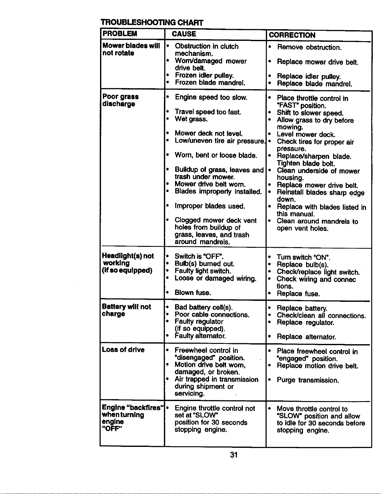
TROUBLESHOOTING CHART
PROBLEM CAUSE CORRECTION
Mower blades will Obstruction in clutch • Remove obstruction.
not rotate mechanism.
• Worn/damaged mower • Replace mower drive belt.
drive belt.
• Frozen idler pulley. • Replace idler pulley.
• Frozen blade mandrel. * Replace blade mandrel.
Poor grass • Engine speed too slow.
discharge
Headlight(s) not
working
(if so equipped)
Battery will not
charge
Loss of drive
Engine "backfires'
whentumlng
engine
"OFF"
• Travel speed too fast.
• Wet grass.
• Mower deck not level.
• Low/uneven tire air pressure
• Worn, bent or loose blade.
• Buildup of grass, leaves and
trash under mower.
• Mower drive belt wom.
• Blades improperly installed.
• Improper blades used.
Clogged mower deck vent
holes from buildup of
grass, leaves, and trash
around mandrels.
Switch is=OFF'.
Bulb(s) burned out.
• Faulty lightswitch.
• Loose or damaged wiring.
• Blown fuse.
'. Bad battery cell(s).
• Poor cable connections.
• Faulty regulator
(if so equipped).
• Faulty alternator.
• Freewheel control in
"disengaged" position.
• Motion drive belt worn,
damaged, or broken.
• Air trapped in transmission
dudng shipment or
servicing.
Engine throttle control not
set at "SLOW_
position for 30 seconds
stopping engine.
• Place throttle control in
"FAST" position.
• Shift to slower speed.
• Allow grass to dry before
mowing.
• Level mower deck.
• Check tires for proper air
pressure.
• Replace/sharpen blade.
Tighten blade bolt.
• Clean underside of mower
housing.
• Replace mower ddve belt.
• Reinstall blades sharp edge
down.
• Replace with blades listed in
this manual.
• Clean around mandrels to
open vent holes.
• Turn switch=ON".
• Replace bulb(s).
• Check/replace light switch.
• Check widng and connec
tions.
• Replace fuse.
• Replace battery.
• Check/clean all connections.
• Replace regulator.
• Replace alternator.
• Place freewheel control in
"engaged" position.
• Replace motion ddve belt.
• Purge transmission.
Move throttle control to
"SLOW* position and allow
to idle for 30 seconds before
stopping engine.
31

32
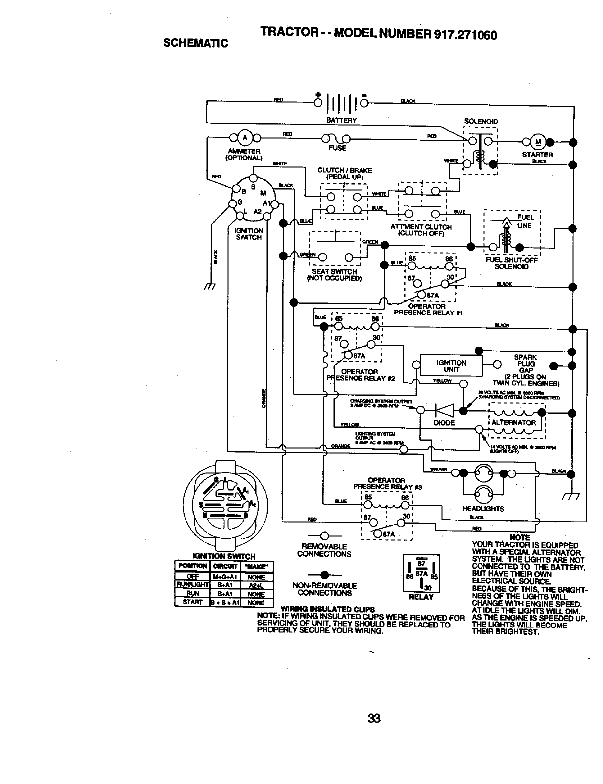
TRACTOR -- MODEL NUMBER 917.271060
SCHEMATIC
I
t ....... I
I
I
SEATSWITCH
(NOTOCCUPIEO)
AMMETER
(OP_ORAL)
OPEP_TOR
t
J
OPERATOR
PRESENCE RELAY #1
IGNITION SWITCH
OPERATOR
PRESENCERELAY113
i
187 , 30I
@ J
REMOVABLE
CONNECTIONS_
NON-REMOVABLE
CONNECTIONS RELAY
WIRING IINSUt.ATED CLIPS
NOTE: IF WtRiNG tNSUU_TED CUPS WERE REMOVED FOR
SERVICING OF UNIT. THEY SHOULD 8E REPLACED TO
PROPERLY SECURE yOUR WIRING.
NOl1£
YOUR TFtACTORIS EQUiPPEO
WITH ASPEQAL ALTERNA'IOFt
SYSTEM. "hiE LIGHTS ARE NOT
CONNECTED TO THE BATTERY,
BUT HAVE THBR OWN
ELECTRICAL SOURCE.
BECAUSE OF THIS, THE BRIGHT-
HESS OF THE UGHTS WILL
CHANGE WITH ENGINE SPEED.
AT IDt.E THE LIGHTS WILL DiM.
AS THE ENGINE IS SPEEOEO UP,
THE UGHTS WiLL BECOME
THEIR BRIGHTEST.
33
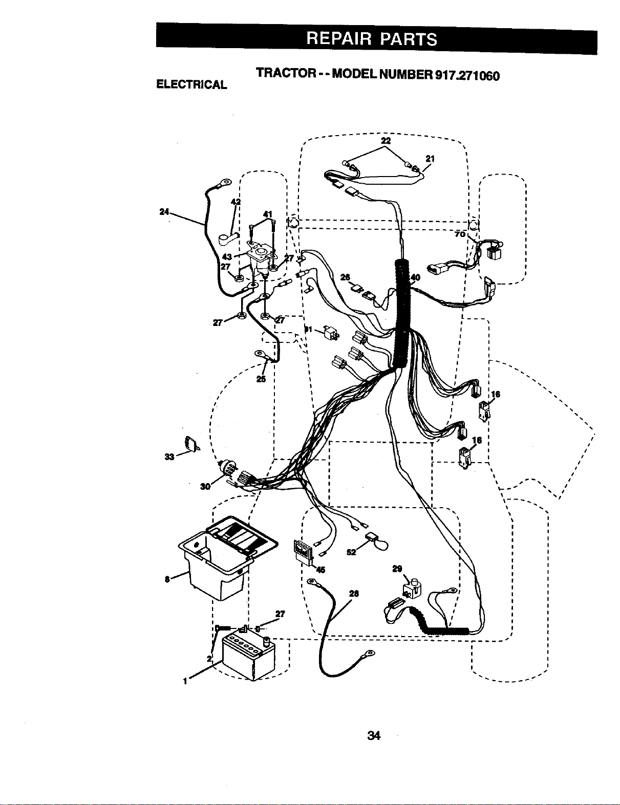
TRACTOR -- MODEL NUMBER917.271060
ELECTRICAL
I
I
I
I I
I I
I
I I
I
I I
I
41
1
I
1
t
t
I
t
\
t
21
I
I
I €
I i
I I
I 1
I I
I_ I
701 *l
11
#
t
I
t
T
I
I
I
I
I
I
I
I
I
I
s I
I
I
I
I
34
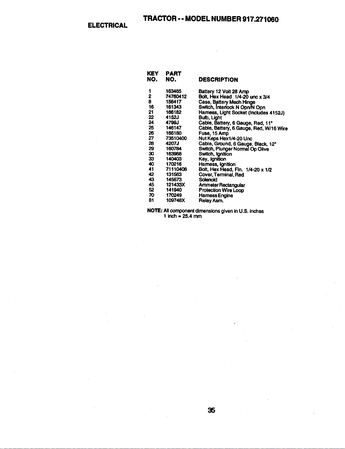
TRACTOR -- MODEL NUMBER 917.271060
ELECTRICAL
KEY PART
NO. NO. DESCRIPTION
1 163465
2 74760412
8 156417
16 161343
21 166182
22 4152J
24 4799,1
25 146147
26 166180
27 73510400
28 4207J
29 160784
3O 16,3968
33 14O403
40 170216
41 71110408
42 131563
43 145673
45 121433X
52 141940
70 170249
81 109748X
Battery 12 Volt 25 Amp
Bolt. Hex Head 1/4-20 unc x 3/4
Case. Ba.tteryMech Hinge
Swttch,Interlock N Opn/N Opn
Harness, LightSocket (Includes 4152J)
Bu_, Light
Cable, Battery, 6 Gauge, Red, 11•
Cable, Batten/. 6 Gauge. Red. W/16 Wire
Fuse, 15Amp
Nut KepsHexl/4-20 Unc
Cable, Ground, 6 Gauge, Black, 12"
Switch,Plunger NormalOp Olive
Switch, Ignition
Key, Ignition
t-tames,s,ignition
Bolt, Hex Head, Fin. 1/4-20 x 1/2
Cover,Terminal, Red
Solenoid
AmmeterRectangular
ProteollonWlre Loop
HarnessEngina
Relay Asm.
NOTE:NI componentdimensionsgiveninU.S.inches
1 inch=25.4 mm
35

TRACTOR - - MODELNUMBER917.271060
CHASSISAND ENCLOSURES
58 12
ss
f_
2O6
74
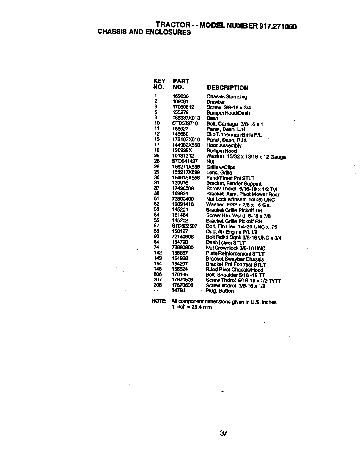
TRACTOR -- MODEL NUMBER 917.271060
CHASSIS AND ENCLOSURES
KEY PART
NO. NO. DESCRIPTION
1 169830 ChesslsStamping
2 169061 Drawbar
3 17060612 Screw 3/6`16 x 3/4
5 155272 BumperHood/Dash
9 168337X013 Dash
10 STD533710 Bolt,Cardage 3/8-16 x 1
11 155927 Panel, Dash, LH.
12 145660 ClipTlnnerman GdlleP/L
13 172107X010 Panel, Dash, R.H.
17 144983X558 HoodAssembly
18 126938X BumperHood
25 19131312 Washer 13/32 x 13/16 x 12 Gauge
26 _1437 Nut
28 166271X558 Gr_law/CUps
29 155217X599 Lens, Gdlla
30 164918X558 Fend/Ftrest PntSTLT
31 139976 Bracket, Fender SuPport
37 17490508 Screw Thdrol 5/16`18 x 1/2 Tyt
38 169834 Bracket Asm. PivotMower Rear
51 73800400 Nut Lockw/Insert 1/4-20 UNC
52 19091416 Washer 9/32 x 7/8 x 16 Ga.
53 • 145201 Bracket GrittePIckofl Lit
54 161464 Screw Hex Wshd 8-18 x 7/8
55 145202 Bracket Gdlle PIckoffRH
57 S'11To22507 Bolt,Rn Hex I14-20 UNC x .75
58 150127 DuctAir Engine P/LLT
60 72140606 BottRdhd Sqnk3/8-18 UNC x 3/4
64 154798 DashLowerSTLT
74 73680600 NutCrownlock3/8-16 UNC
142 165867 Plate ReinforcementS11.T
143 154966 Bracket Swaybar Chassis
• 144 154207 Bracket Pnt Footrest STLT
145 156524 RJod PivotChessls/Hood
206 170165 Bolt Shoulder 5/16 -18 1-1"
207 17670508 _rew'l'hdrct 5/16-18 x 1/2 TY'I-r
208 17670606 Screw Thdrol 3/8-16 x 1/2
- - 5479J Ptug, Button
NOTE: AUcomponentdimensions given in U.S. Inches
1 Inch= 25.4 mm
37
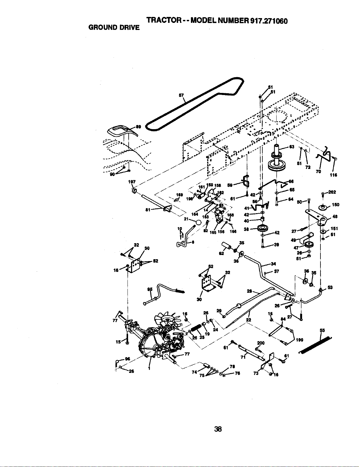
TRACTOR-- MODEL NUMBER 917.271060
GROUND DRIVE
; 156 166
35
/v
38
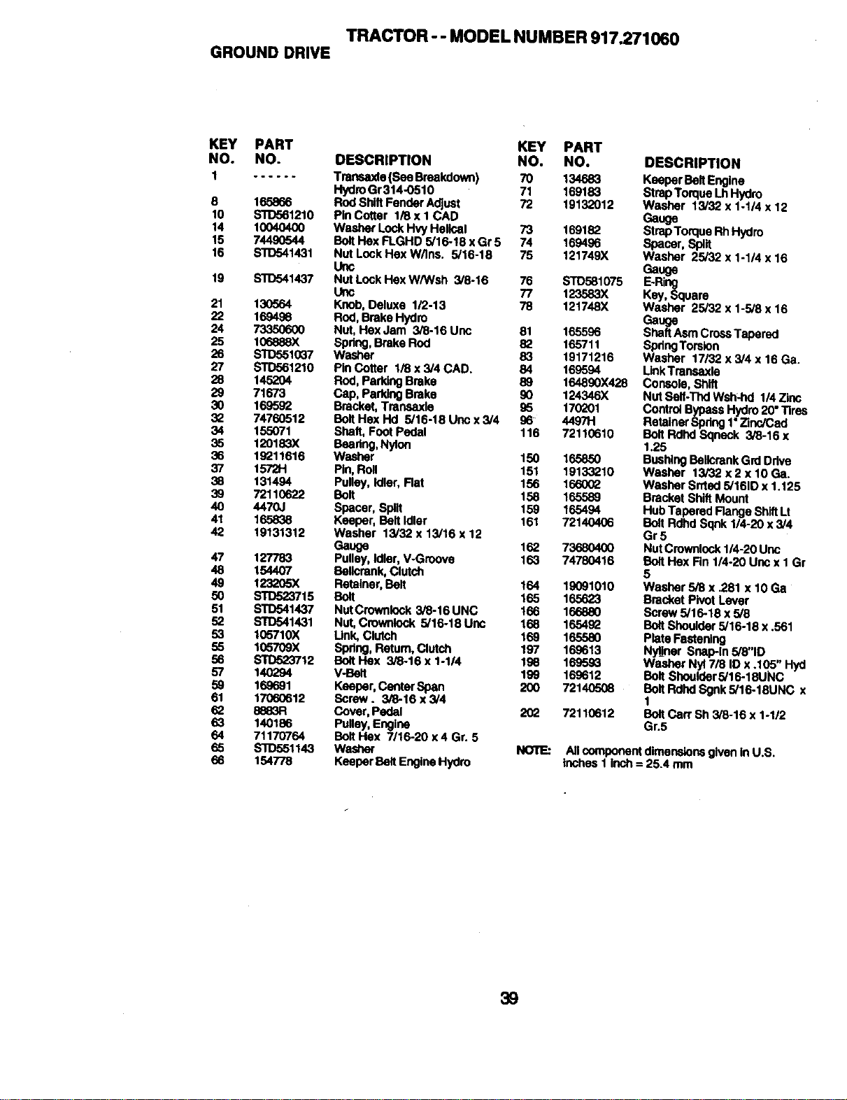
TRACTOR -- MODEL NUMBER 917.271060
GROUNDDRIVE
KEY PART KEY PART
NO. NO. DESCRIPTION NO. NO.
1 ...... Tra_,_.de (See Breakdown) 70 134683
HydroGr314-0510 71 169183
8 165866 RodShiftFender Adjust 72 19132012
10 $10561210 PidCotter 1/8xl CAD
14 10040400 Wecher LockHvy Helical 73 169182
15 74490544 BoltHex FLGHD 5/16-18 x Gr 5 74 169496
16 S'10541431 Nut LockHex W/Ins. 5/16-18 75 121749X
Uflc
19 STO541437 Nut LockHex W/Wsh 3/8-16 76 STD581075
Uric 77 123583X
21 130564 Knob, Detuxe 1/2-13 78 121748X
22 169498 Rod, Brake Hydro
24 73350600 Nut, Hex Jam 3/8-16 Unc 81 165596
25 106888X Spdng, Brake Rod 82 165711
26 S'I1Yo51037 Washer 83 19171216
27 STD561210 Pin Cotter 1/8 x 3/4 CAD. 84 169594
28 145204 Rod, ParkingBrake 89 164890X428
29 71673 Cap, ParkingBrake 90 124346X
30 169592 Bracket,Transaxle 95 170201
3_ 74760512 BoltHex Hd .5/16-18 Unc x 3/4 96 449711
34 155071 Shaft, Foot Pedal 116 72110610
35 120183X Beedng,Nyloo
36 19211616 Washer 150 165850
37 1572H Pin,Roll 151 19133210
38 131494 Pulley, Idler, Rat 156 166002
39 72110622 Bolt 158 165589
40 4470J Spacer, Split 159 165494
41 165838 Keeper, Belt idler 161 72140406
42 19131312 Washer 13/32 x 13/16 x 12
Gauge 162 73680400
47 127783 Pulley, Idler, V-Groove 163 74780416
48 154407 Bellcmnk, Clutch
49 123205X Retalner, Bolt 164 19091010
50 STD523715 Bolt 165 165623
51 8_1437 Nut Crownlock 3/8-16 UNC 166 166880
52 s'rD541431 Nut, Cmwnlock 5/16-18 Unc 168 165492
53 105710X Link, Clutch 169 165580
55 I_X Sp_lng,Return,Clutch 197 169613
56 STD523712 Bo#tHex 3/8-16 x 1-1/4 198 169593
57 140294 V-Belt 199 169612
59 169691 Keeper,Center Span 200 72140508
61 17060612 Screw. 3/8-16 x 3/4
62 8_83R Cover, Pedal 202 72110612
63 140186 Pulley, Engine
64 71170764 Bo_tHex 7/16-20 x4 Gr. 5
65 _1143 W_ NOTE:
66 154778 Keeper Belt EngineHydro
DESCRIPTION
Keeper BeltEngine
StrapTorque LhHydro
Washer 13/32 x 1-1/4 x 12
Gauge
StrapTorque RhHydro
Spacer, Split
Washer 25/32 x 1-1/4 x 16
Gauge
E-Ring
Key, Square
Wesher 25J32 x 1-5/8x 16
Ga
s_aU_eAsmCrossTapered
SpdngTorsion
Washer 17/32 x 3/4 x 16 Ge.
Unk Transaxla
Console, Shift
Nut Self-Thd Wsh-hd I14 Zinc
Control Bypass Hydro 20"Tires
RetainerSqdng I •Zinc/Cad
Bolt Rdhd So.nsck 3/8-16 x
1.25
BushingBellcrankGrd Drive
Washer 13/32 x 2 x 10 Ga.
Washer Srrted 5/161Dx 1.125
Bracket Shift Mount
Hub Tapered Range ShiftLt
Bolt Rdhd Sqnk 1/4-20 x 3/4
Gr5
Nut Crownlock1/4-20 Uric
BoltHex Rn 1/4-20 Unc x I Gr
5
Washer 5/8 x .281 x 10 Ga
Bracket Pivot Lever
Screw 5/16-18 x 5/8
BoltShoulder5/16-18 x .561
Plate Fastening
Nyl_ner Sr_p-tn 5/8"10
Washer Nyl 7/8 ID x .105" Hyd
Bolt Shoulder5/16-1BUNC
BoltRdhd Sgnk 5/15-18UNC x
1
BoltCart Sh 3/8-16 x 1-1/2
Gr.5
All componentdimensionsgiven inU.S.
Inches 1inch = 25.4 mm
39
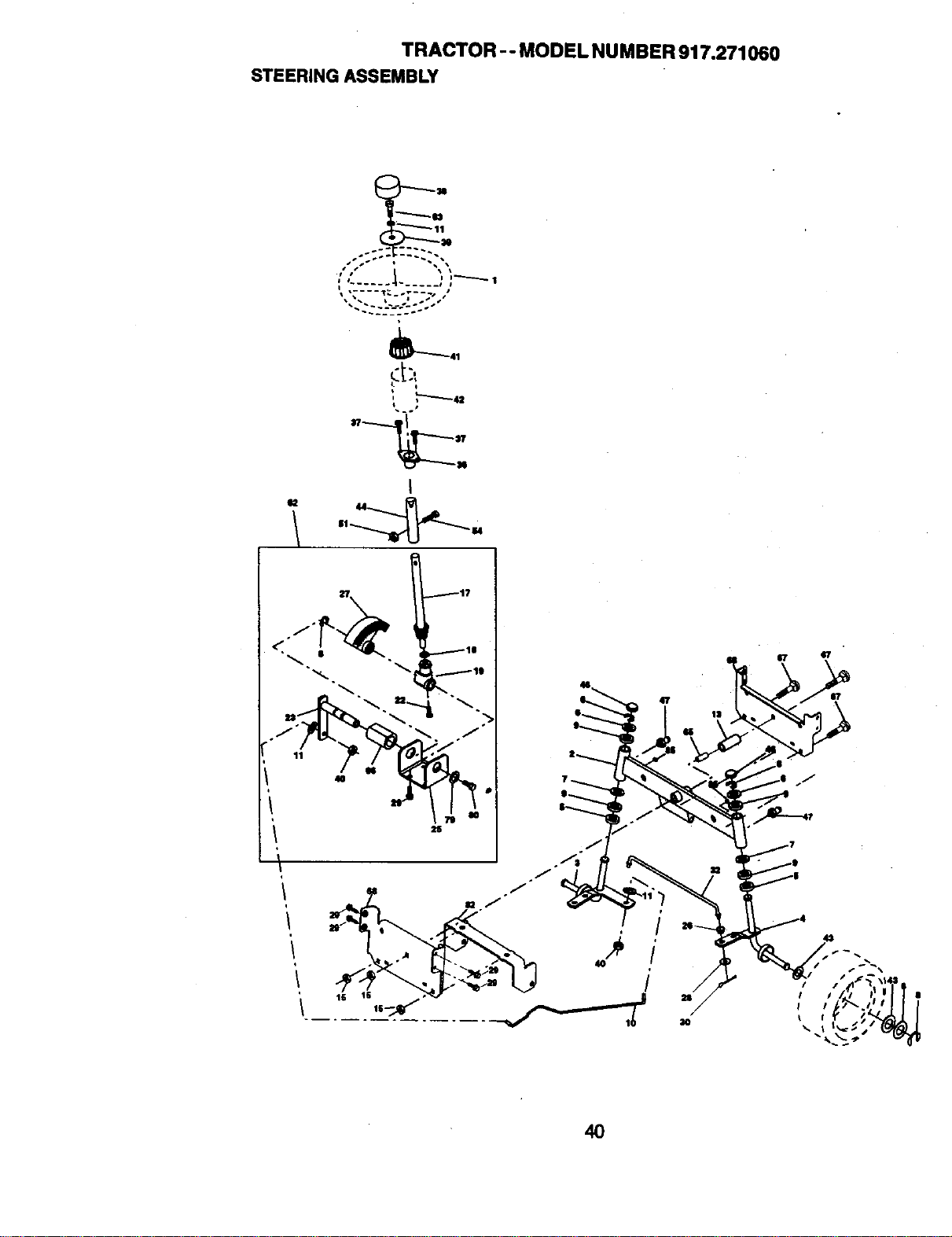
TRACTOR -. MODEL NUMBER 917.271060
STEERINGASSEMBLY
:,'......_-.____,)_---,
,c :i
I
40
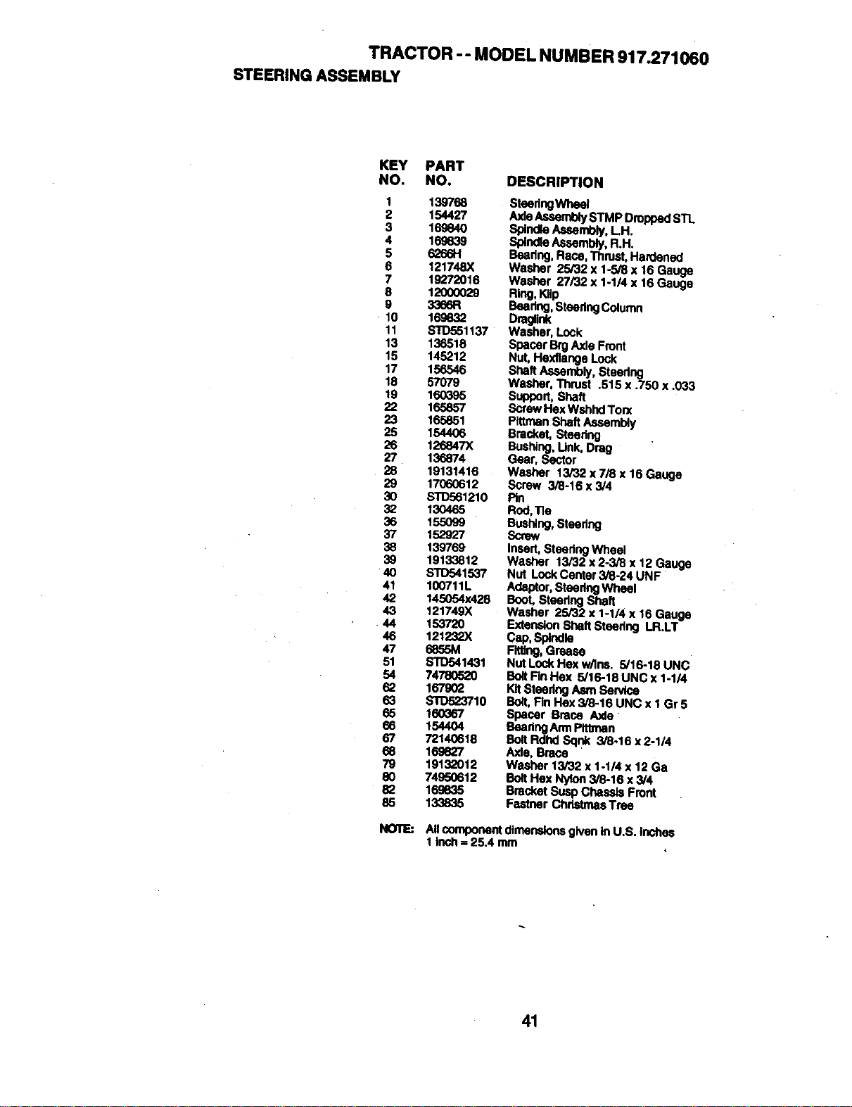
TRACTOR -- MODEL NUMBER 917.271060
STEERINGASSEMBLY
KEY PART
NO. NO. DESCRIPTION
1 1397"o8
2 154427
3 16984O
4 16_839
5
6 121748X
7 19272016
8 1200OO29
9 3366R
10 169832
11 $10551137
13 136518
15 145212
17 156546
18 57079
t9 160395
22 165857
23 165851
25 154406
26 126847)(
27 136874
2B 19131416
29 17060612
3O STD561210
32 130465
36 155O99
37 152927
38 139769
39 19133812
4O $11To41537
41 100711L
42 145054X428
43 121749)(
44 15372O
46 121232X
47 6855M
51 STD541431
54 74780520
62 167902
63 STD523710
65 160G67
66 1544O4
67 72140618
68 169827
79 19132012
80 74950612
82 169835
85 133835
NOTE:
SteedngWheel
AxleAssemblySTMP Dropped STL
Splnd4eAssembly,LH,
SpindleAssembly,R.H.
Beadng,Race, Thrust,Hardened
Washer 25/32 x 1-5/8 x 16 Gauge
Washer 27/32 x 1-1/4 x 16 Gauge
ng,SteedngColumn
Dm_ink
Washer, Look
Spacer Brg Axle Front
Nut, Hexltange Lock
Shaft Assembly, Steedng
Washer, Thrust .515 x .750 x .033
suppon, Shaft
ScrewHex WshhdTon(
PittrnanShaft Assembly
Bracket, Steering
Bushing, Link,Drag
Gear, Sector
Washer 13/82 x 7/8 x 16 Gauge
Screw 3/8-I 6 x 3/4
Pin
Rod,Tie
Bushing, Steedng
Screw
Insert, Steedng Wheel
Washer 13/32 x 2-3/8 x 12 Gauge
Nut LockCenter 3/3-24 UNF
Adaptor,SteeringWheel
Boot,Steedng Shaft
Washer 25/32 x 1-1/4 x 16 Gauge
ExtensionShaft Steering LR.LT
Cap,Spindle
Fitting,Grease
Nut Lock Hex w/Ins. 5/16-18 UNC
BoltRn Hex 5/16-18 UNC x 1-114
Kit_eedng Asm Service
Bolt,Fin Hex 3/8-16 UNC x 1 Gr5
Spacer Brace Axle
Beedng AmtPlttman
BoltRdhd Sqnk 3/8.16 x2-1/4
Axle, Brace
Washer 13/32 x 1-1/4 x 12 Ga
BoltHex Nylon 3/8-16 x3/4
Bracket SuapChassis Front
Fastner ChristmasTree
All component dimensionsgiven In U.S. Inches
1klch = 25.4 mm
41
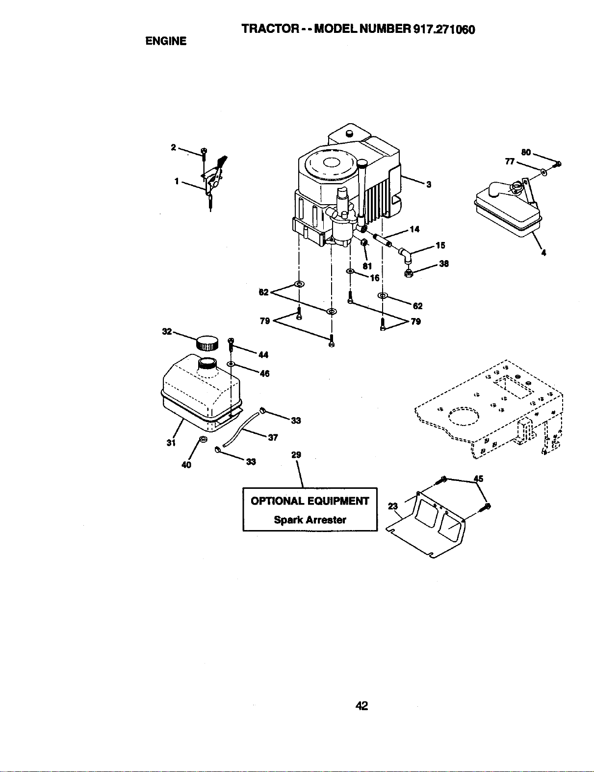
TRACTOR -- MODEL NUMBER 9172.71060
ENGINE
4
44 "_
33
33 29
I OPTIONAL EQUIPMENT
Spark Arrester
S_ L: _ p_ i
42
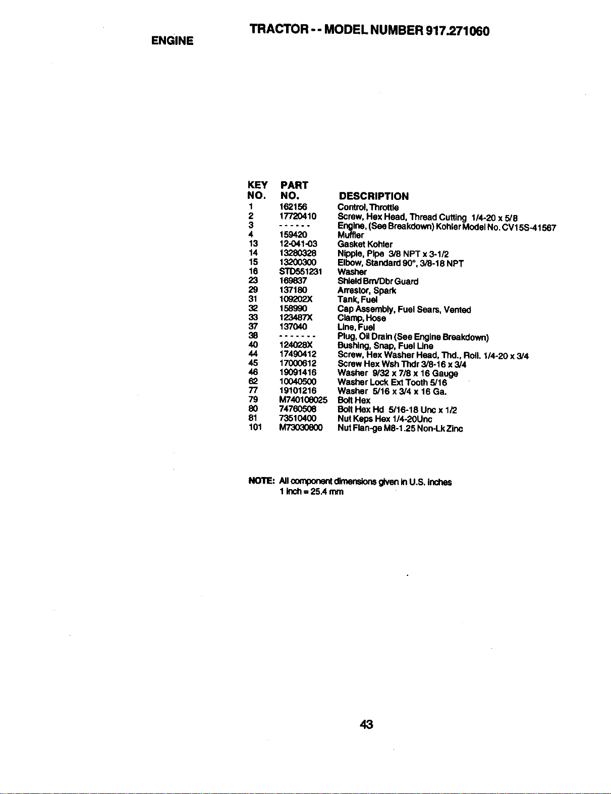
TRACTOR -- MODEL NUMBER 917.271060
ENGINE
KEY PART
NO. NO.
1 162156
2 17720410
3 ---_-°
4 159420
13 12-041-03
14 13280328
15 13200300
16 S'rD551231
23 169837
29 137180
31 109"202)(
32 158990
33 123487X
37 137040
40 124028X
44 17490412
45 17000612
46 19091416
62 10040500
77 19101216
79 M740108025
80 74760506
81 73510400
101 M73030800
DESCRIPTION
Control,Throttle
Screw, Hex Head, Thread Cuffing 1/4-20 x 5/8
Engine, (See Breakdown)KohlerModel No. CV15S-41567
Muffler
Gasket Kohlar
Nipple, Pipe 3/8 NPT x 3-1/2
Elbow, Standard90°, 3/8-18 NPT
Washer
ShieldBrn/DbrGuard
Arrestor, Spark
Tank, Fuel
Cap Assembly, FuelSears, Vented
Clamp,Hose
Line,Fuel
Plug,OilDrain (See EngineBreakdown)
Bushing, Snap, Fuel Llna
Screw, Hex Washer Head, Thd., Roll. 1/4-20 x 3/4
Screw Hex Wsh Thdr 3/8-16 x 3/4
Washer 9/32 x7/8 x 16 Gauge
Washer Lock ExtTooth 5/16
Washer 5/16 x 3/4 x 16 Ga.
BoltHex
BoltHex Hd 5/16-18 Unc x 1/2
Nut Keps Hex 1/4-20Unc
Nut Flan-ge M8-1.25 Non-Lk Zinc
NOTE: Allcomponentdimensionsgiven InU.S. inches
1inch= 25A mm
43
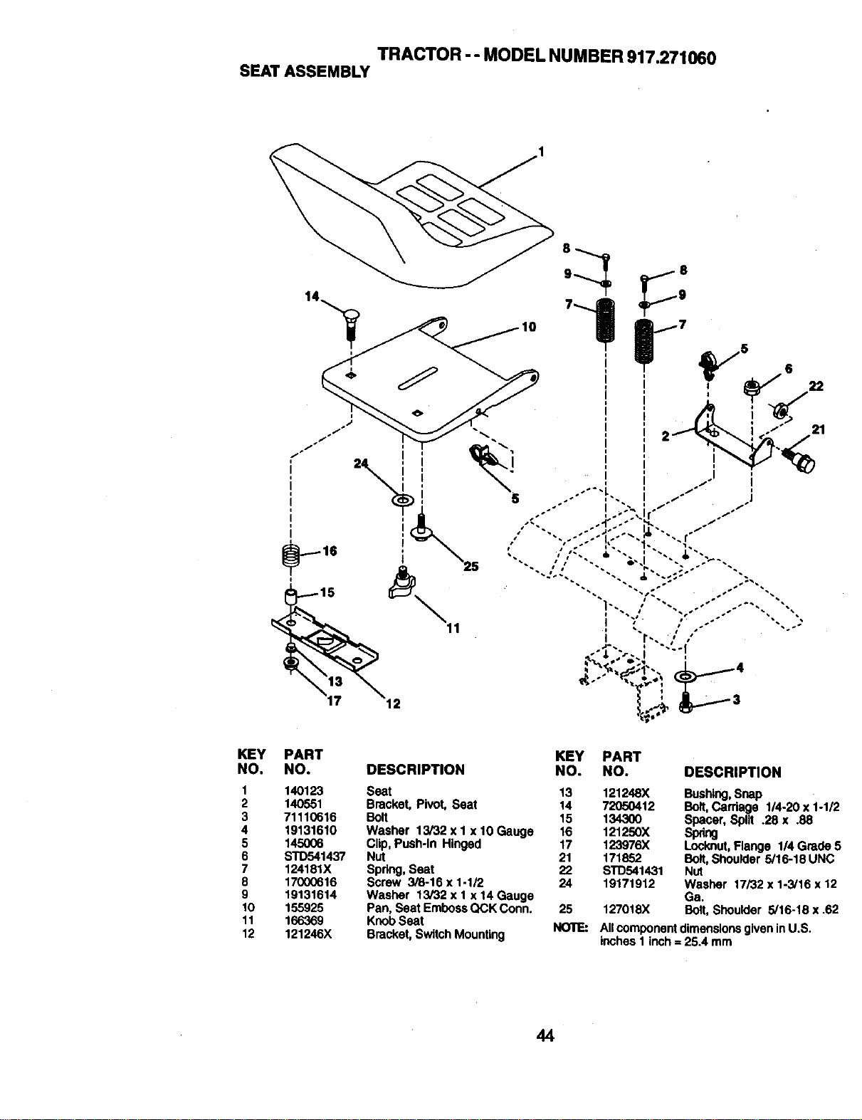
TRACTOR -- MODEL NUMBER 917.271060
SEATASSEMBLY
KEY
NO.
I
2
3
4
5
6
7
6
9
IO
11
12
PART KEY PART
NO. DESCRIPTION NO. NO. DESCRIPTION
140123 Seat 13 121248X Bushing,Snap
140551 Bracket, Pivot, Seat 14 72050412 Bolt,Carriage 1/4-20 x i-1/2
71110616 Bolt 15 134300 Spacer, Spilt .26 x .88
19131610 Washer 13/32 x I x 10 Gauge 16 121250X Spdng
145006 Clip,Push-In Hinged 17 123976X Locknut, Flange 114Grade 5
STD541437 Nut 21 171852 Bolt,Shoulder 5/16-18 UNC
124181X Spdng, Seat 22 STD541431 Nut
17000616 Screw 3/8-16 x 1-1/2 24 19171912 Washer 17/32 x 1-3/16 x 12
19131614 Washer 13/32 x 1 x 14 Gauge Ga.
155925 Pan, Seat Emboss QCK Conn. 25 127018X Bolt, Shoulder 5/16-18 x .62
166369 KnobSeat
121246X Bracket, Switch Mounting NOTE: Allcomponent dimensionsgiven inU.S.
Inches 1 inch= 25.4 mm
44
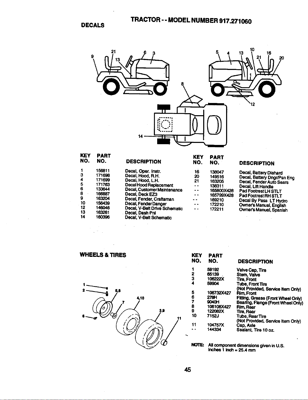
TRACTOR -- MODEL NUMBER 917.271060
DECALS
21
10
5_ 4 13 16
2O
KEY PART
NO. NO.
1 156811
3 171698
4 171699
5 171763
6 133644
8 166887
9 1632O4
10 156439
12 146046
13 163261
14 160396
KEY PART
DESCRIPTION NO. NO.
Decal, Oper. Instr. 16 138047
Decal, Hood,R.H. 20 149516
Decal;Hood, LH. 21 1632_5
Decal HoodReplacament - - 138311
Oeca|,Customer Maintenanea - - 165800X428
Decal, Deck EZ3 - - 165799X428
Oecal, Fender,Creftsman - - 169210
Decal,FenderDanger -. 172210
Decal, V-Belt Drive Schematic - - 172211
Decal, Dash Pnl
Decal, V-Belt Schematic
DESCRIPTION
Decal, Bettery Diehard
Decal, Battery Dngr/Psn Eng
Decal, Fender AutoSears
Decal,Lift Handle
PadFootrestLH STLT
PadFootrestRH STLT
Decal By Pass LT Hydro
Owner'sManual, English
Owner'sManual, Spaolsh
WHEELS & TIRES
4,10
KEY PART
NO. NO.
1
2
3
4
5
6
7
8
9
10
11
11
DESCRIPTION
59192 Valve Cap, Tire
65139 . Stm, Valve
106222X Tire, Front
59904 Tube, FrontTire
(Not Provided, Service ItemOnly]
106732X427 Rim,Froot
2781"1 Fitting,Grease (FrontWile_elOnly)
90401-1 Beadng, Flange(Frontwheel Only
106108X42"/ Rim, Rear
122082X Tire, Rear
7152J Tube, Reer"llre
(Nat Provided, Service ItemOnly)
I O4757)( Cap, Axle
144334 Sealant, Tire 10 oz.
All component dimensionsgiven in U.S.
Inches I Inch= 25.4 mm
45
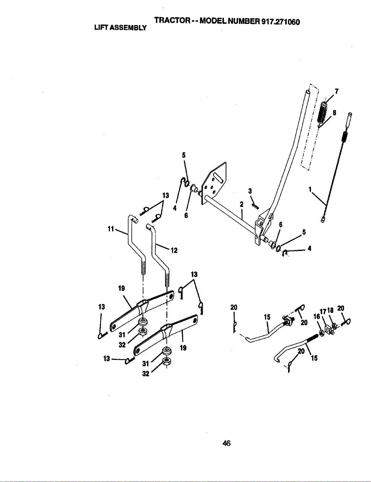
TRACTOR -- MODEL NUMBER 917.271060
LIFTASSEMBLY
13
46
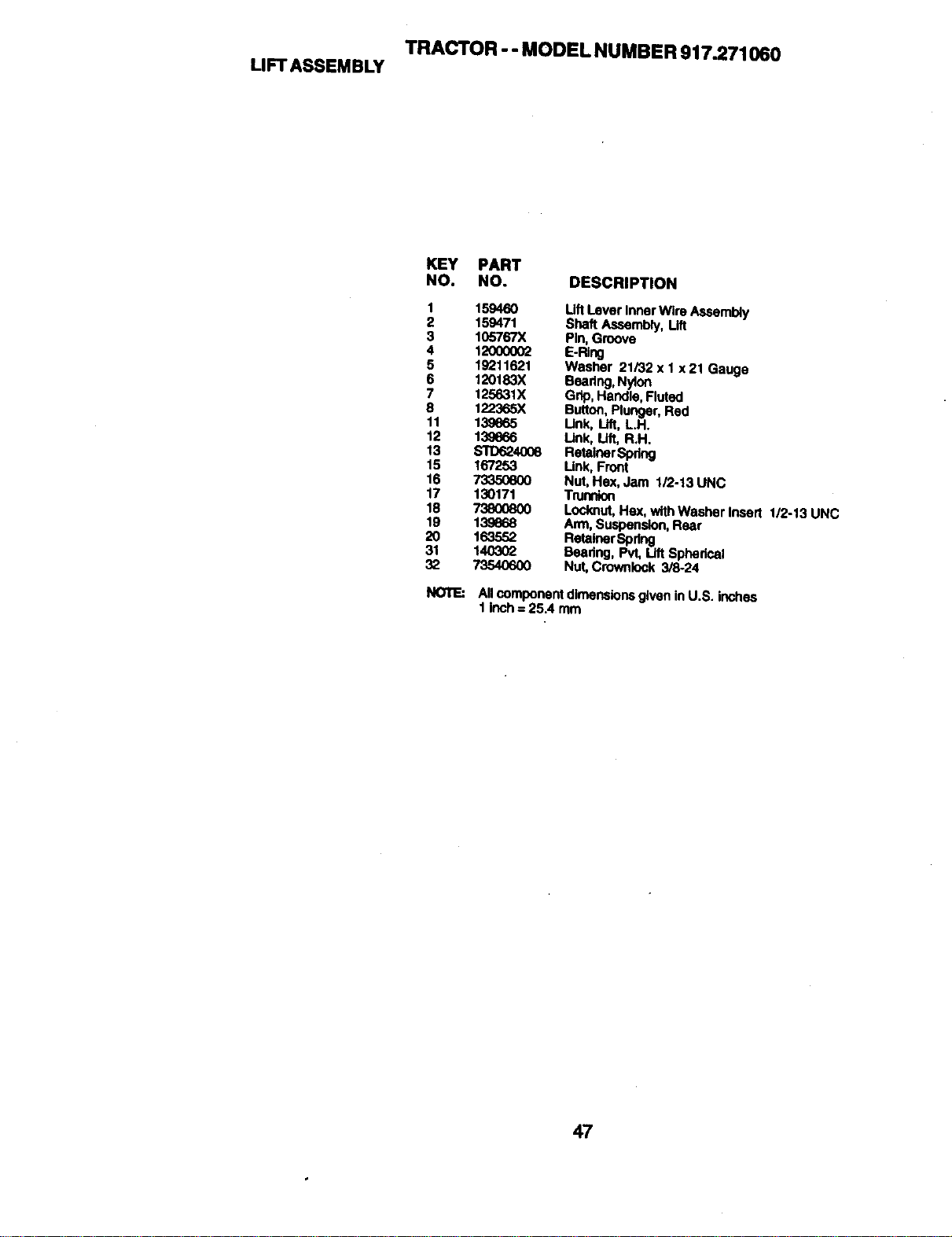
TRACTOR - - MODEL NUMBER 917.271060
LIFT ASSEMBLY
KEY PART
NO. NO. DESCRIPTION
1 159460 LiftLever Inner Wire Asseml_y
2 159471 Shaft Assembly, Lift
3 105767X Pin, Groove
4 12000002 E.RIr_
5 19211621 Washer 21/32 x 1x 21 Gauge
6 120183X Beadn9, Nyion
7 125631X Gdp, Handle, Fluted
8 122365X Button, Plunger, Red
11 13_65 Unk, Lid, L.H.
12 13_66 Unk, Lift, R.H.
13 $1"D624008 Retainer,Spring
15 167253 Unk, Front
16 _ Nut,Hex, Jam 1/2-13 UNC
17 130171 Trunnion
18 73800800 Locknut, Hes, with Weshar Ineatt 1/2-13 UNC
19 139668 Arm, Suspension,Rear
20 163552 RetainerSpdng
31 140302 Beadng, Pvt, Lift Spherical
32 73540600 Nut, Crownlock 3/8-24
NOTE:
All componentdimensionsgiven inU.S. inches
1 Inch= 25.4 mm
47
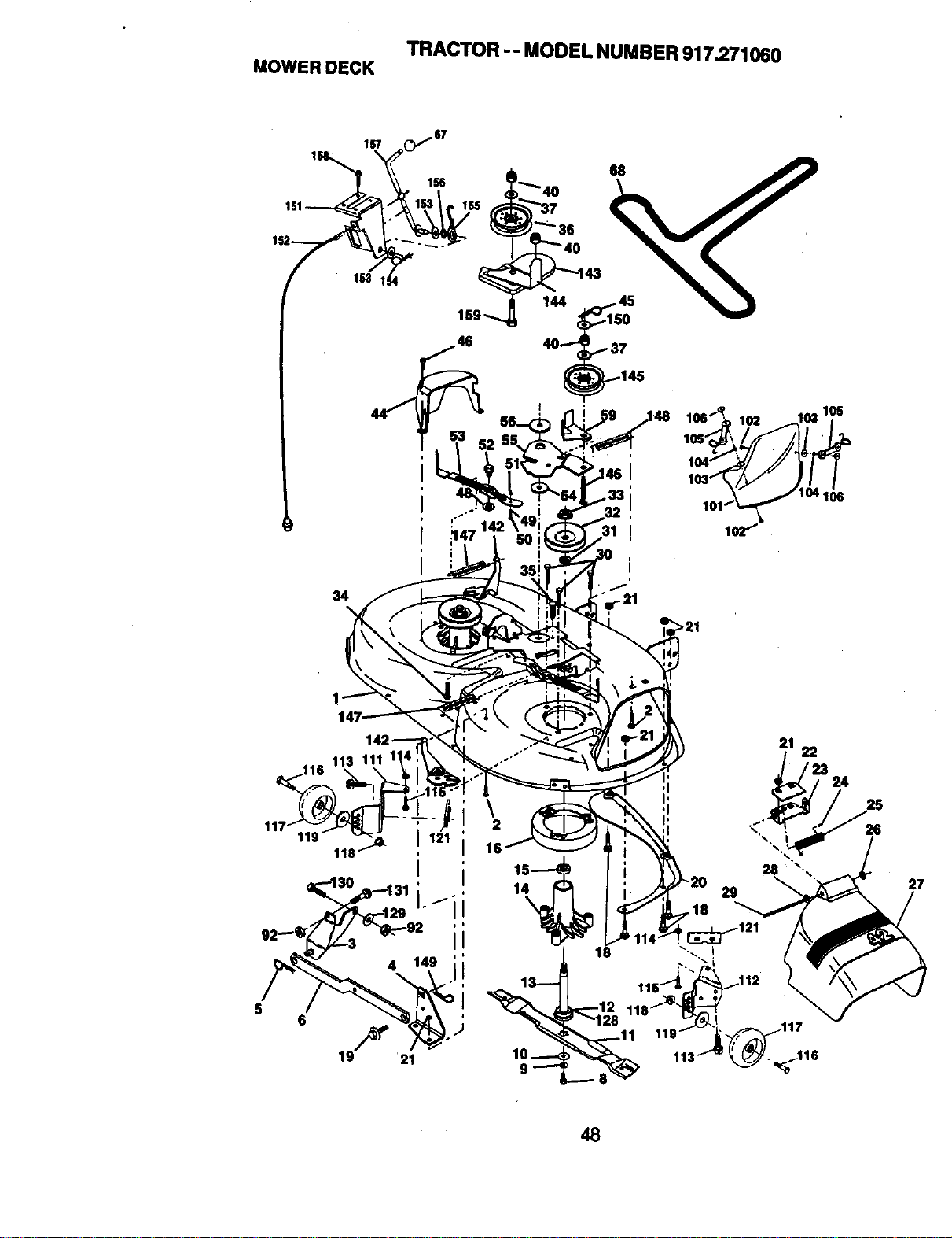
TRACTOR -- MODEL NUMBER917.271060
MOWERDECK
167
68
I
\
2
16
1
18
>21
21
223 24
_117
26
27
48
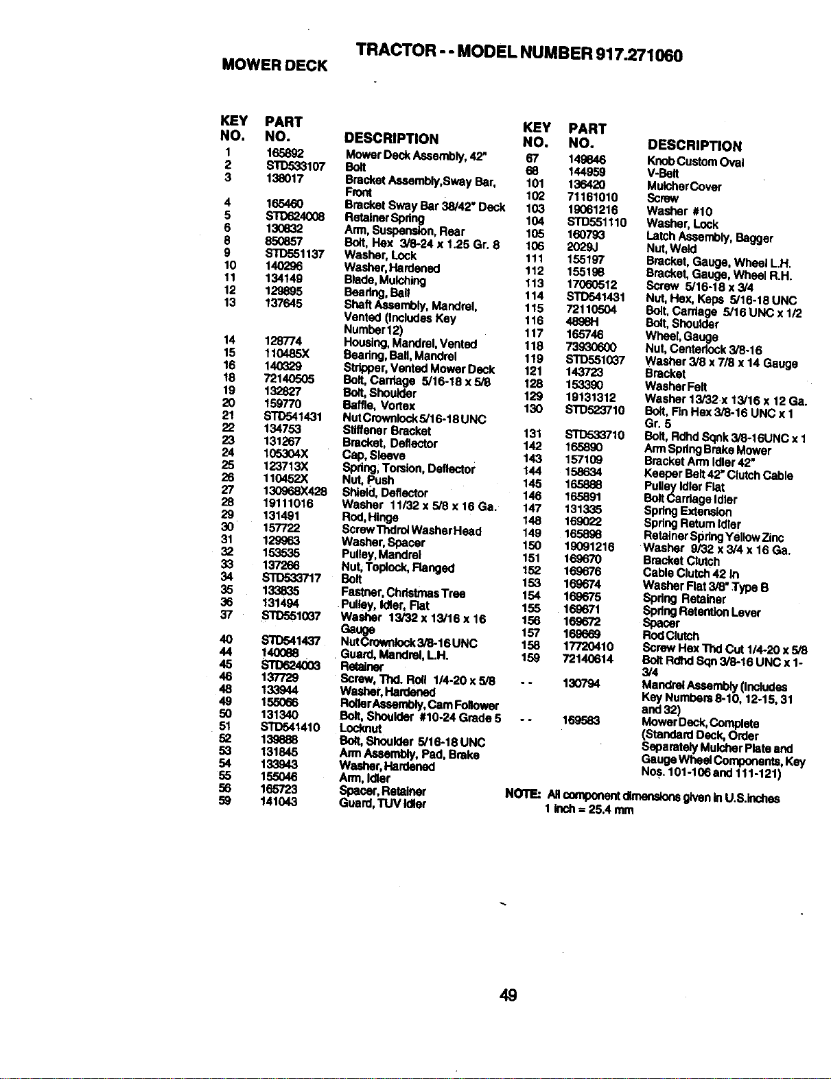
TRACTOR - - MODEL NUMBER 917.271060
MOWER DECK
KEY PART
NO. NO.
1 165892
2 STD533107
3 138017
4 165460
5 S'IO624008
6 130832
8 85O857
9 STD551137
10 140296
11 134149
12 129895
13 137645
14 128774
15 110485X
16 140329
18 72140505
19 132827
I_0
22 134753
23 131267
24 105304X
25 123713X
26 110452X
27 130968X428
28 19111016
29 131491
3O 157722
31 129963
32 153535
33 137266
34 STD533717
35 133835
36 131494
37 $1"D5510_7
40 s'rIx_1437
44 14OO88
45 S'rD624003
46 137729
48 133944
49 155066
5o 13134o
51 STD541410
52 139888
53 131845
54 133943
55 155046
56 165723
59 141043
KEY PART
DESCRIPTION NO. NO.
Mower Deck Assembly, 42, 67 149846
Bolt 68 144959
Bracket Assembly,Sway Bar, 101 136420
Free( 102 71161010
Bracket Sway Bar 38/42" Deck 103 19061216
RetainerSpdng 104 STD551110
Ann,Suspension,Rear 105 160793
Bolt, Hex 3/8-24 x 1.25 Gr. 8 106 2029J
Washer, Lock 111 155197
Washer,Hardened 112 155198
Blade, Mulching 113 17060512
Beadng,Bail 114 STD541431
Shell Assembly, Mandrel, 115 72110504
Vented (Indedas Key 116 489814
Number 12) 117 165746
Housing, MandmI, Vented 118 73930600
Beering, Ball,Mandrel 119 STD551037
Stripper,Vented Mower Deck 121 143723
Bolt,Carriage 5/16-18 x 5/8 128 153390
Bolt,Shoulder 129 19131312
Baffle, Vortex 130 STD523710
NutCrownlocks/16-18 UNC
Stiffener Bracket 131 $10533710
Bracket, Deflector 142 165890
Cap, Sleave 143 157109
Spdng;Torsk>n,Deflector 144 158634
Nut, push 145 165888
Shield, Deflector 146 165891
Washer 11/32 x 5/8 x 16 Ga. 147 131335
Rod, Hinge 148 169022
ScrewThdroiWasherHeed 149 165898
Washer, Spacer 150 19091216
Pulley,Mandrel 151 169670
Nut, Taplock, Ranged 152 169676
Bolt 153 169674
Featner,ChrlatmasTrae 154 169675
•Pulley, Idler, Rat 155 169671
Washer 13/32 x 13/16 x 16 156 169672
Gauge 157 169669
NutCrownlock3/8-16 UNC 158 17720410
Guard, Mandrel, L.H. 159 72140614
ReWne¢
Screw, "rhd.Roll 114-20x 5/8 -* 130794
Washer, Hardened
RolterAseambly,Cam Follower
Bolt, Shoulder #10-24 Grade 5 - - 169583
Locknut
Bolt,Shoulder 5/16-18 UNC
AnnAssembly, Pad, Broke
Washer, Hardened
Ann, Idler
Gspacer,RetaJ_er
uard,TUV Idler
DESCRIPTION
KnobCustom Oval
V-Belt
MulcherCover
Screw
Washer #10
Washer, Lock
Latch Assembly,Bagger
Nut, Weld
Bracket,Gauge, Wheel LH.
Bracket,Gauge, Wheel R.H.
Screw 5/16-18 x 3/4
Nut, Hex, Keps 5/16-18 UNC
Bolt,Carriage 5/16 UNC x 1/2
Bolt,Shoulder
Wheel, Gauge
Nut, Centedock 3/8-16
Washer 3/8 x 7/8 x 14 Gauge
Bracket
Washer Felt
Washer 13/32.x 13/16 x 12 Ga.
Bolt,Rn Hex 3/8-16 UNC x 1
Gr. 5
Bolt, RdhdSqnk 3/8-16UNC x 1
Ann SpdngBrake Mower
Bracket Ann Idler 42"
Keeper Belt42"ClutchCable
PulleyIdler Flat
BoltCarriage Idler
Spring Extension
Spring Retum Idler
Retainer SpringYellow Zinc
Washer 9/32 x 3/4 x 16 Ga.
Bracket Clutch
Cable Clutch42 In
Washer Rat 3/8" Type B
Spring Retainer
SpringRetentionLever
Spacer
RodClutch
Screw Hex Thd Cut 1/4-20 x5/8
BoltRdhd Bqn 3/8-16 UNC x 1-
3/4
Mam:k'el,ad_embly(I_lud_s
Key Numbem 8-10, 12-15, 31
and 32)
Mower Deck,Complete
(Standard Deck,Order
Separately Muldner Plate end
Gauge Wheel Components, Key
Nos. 101-106 and 111-121)
NOTE: All_n_aoneatdlmees_ givenInU.S.k-tchas
I Inch= 25.4mm
49
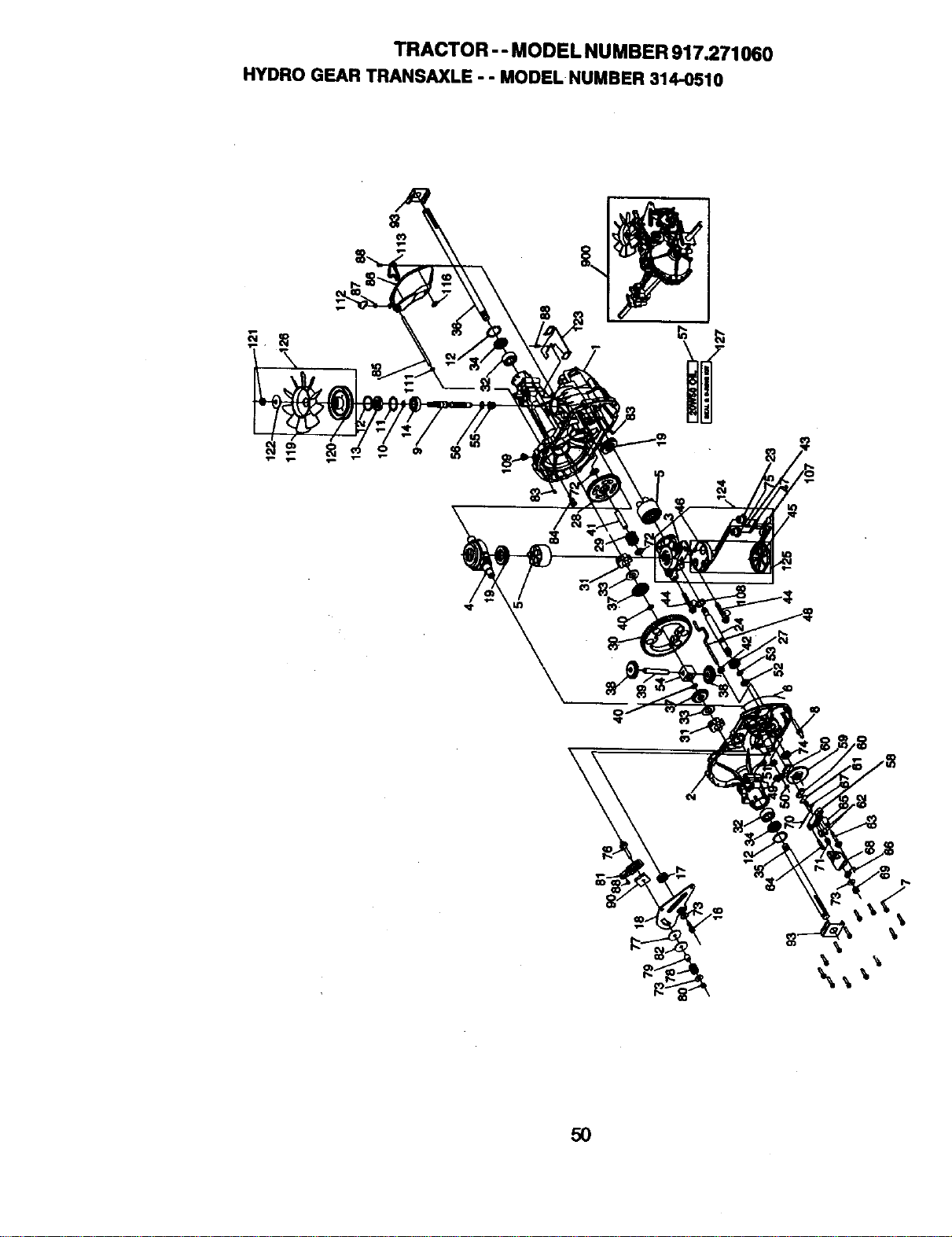
TRACTOR -- MODEL NUMBER 917.271060
HYDROGEARTRANSAXLE- - MODELNUMBER314-0510
\
\
5O
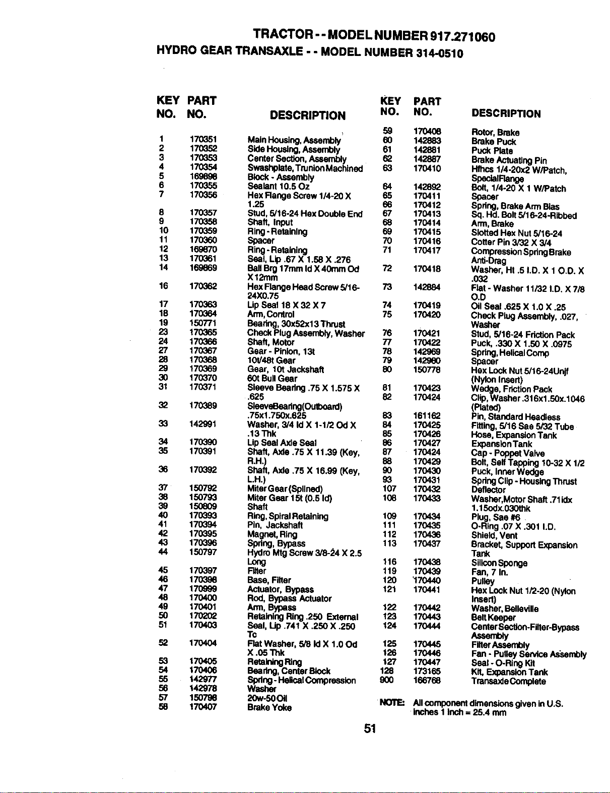
TRACTOR -- MODEL NUMBER 917.271060
HYDROGEARTRANSAXLE- - MODELNUMBER314.O510
KEY PART KEY PART
NO. NO. DESCRIPTION NO. NO.
, 59 1704O6
1 170351 Main Housing,Assembly 60 142883
2 170352 Side Housing, Assembly 61 142881
3 170353 Center Section, Assembly 62 142887
4 170354 Swashplate,TrunionMacblned 63 170410
5 1696ge Block- Assembly
6 170355 Sealant 10,50z 64 142892
7 170356 Hax Range Screw 1/4-20 X 65 170411
1.25 66 170412
8 170357 Stud, 5/16-24 Hex Double End 67 170413
9 170358 Shaft, Input 68 170414
10 170359 Ring- Retaining 69 170415
11 170360 Spacer 70 170416
12 169870 Ring- Retaioing 71 170417
13 170361 Seal, Lip .67 X 1.58 X .276
14 16S669 BallBrg 17ramId X 40ram Od 72 170418
X12mm
16 170362 Hex Flange Head Screw 5/16- 73 142884
24X0.75
17 170363 I Ip Seal 18 X 32 X 7 74 170419
18 170364 Arm,Control 75 170420
19 150771 Beadng, 30x52x13 Thrust
23 170365 Check Plug Assembly,Washer 76 170421
24 170366 Shaft, Motor 77 170422
27 170367 Gear - Pinion,131 78 142969
28 170368 10V48t Gear 79 142960
29 170369 Gear, 10t Jackshaft 80 150778
30 170370 601BullGear
31 170371 Bieave Beadng .75 X 1.575 X 81 170423
.625 82 170424
32 170389 Sleavel_)adng(Oulboard)
.75x1.750x.625 83 161162
33 142991 Washer, 3/4 Id X 1-1/20d X 84 170425
.13 Thk 85 170426
34 1703,90 Lip SealAxle Seal 86 170427
35 170391 Shaft, Axle .75 X 11.39 (Key, 87 170424
R.H.) 88 170429
36 170392 Shaft, Axle .75 X 16.99 (Key, 90 170430
LH.) g_ 170431
37 150792 MitarGear (Bpflned) 107 170432
38 150793 Miter Gear 151(0.5 Id) 108 170433
39 150609 Shaft
40 170393 Ring,SplralRetainlng 109 170434
41 170394 Pln, Jackshaft 111 170435
42 170395 Magnet, Ring 112 170436
43 170396 Spdng, Bypass 113 170437
44 150797 Hydro Mtg Screw 3/8-_'4 X 2.5
Long 116 170438
45 170397 Filler 119 170439
46 1703S8 Base, Filler 120 "170440
47 170999 Actuator, Bypass 121 170441
48 170400 Rod, BypassActuator
49 170401 Arm, Bypass 122 170442
50 170202 RetainingRing .250 External 123 170443
51 170403 Seal, Up .741 X .250 X .250 124 170444
Tc
52 170404 Flat Washer, 5/8 Id X 1.00d 125 170445
X .05 Thk 126 170446
53 170405 RetainklgRing 127 170447
54 170406 Beadng, Center Block 128 173165
55 142977 Spdng - HencalComprassion 900 166768
56 142978 Washer
57 150798 2Ow-50oii NOTE:
58 170407 Brake Yoke
51
DESCRIPTION
Rotor,Brake
Brake Puck
Puck Plate
Brake ActuatlngPin
Hfhce 114-20x2 W/Patch,
SpeclaIRange
Bolt, 1/4-20 X 1 W/Patch
Spacer
Spdng, Brake Arm Bias
Sq, lid. Bolt5/16-24-Ribbed
Arm, Brake
BlottedHex Nut5/16-24
Cotter Pin 3/32 X 3/4
Compression SpringBrake
Anti-Drag
Washer, Ht .5 I.D. X 10.D. X
.032
Flat - Washer 11/32 I.D. X 7/3
O.D
Oil Seal .625 X t.0 X .25
Check Plug Assembly, .027,
Washer
Stud, 5/16-24 FrictionPack
Puck, .330 X 1.50 X .0975
Spdng,HelicalComp
Spacer
Hax Lock Nut 5/16-24Unjf
(Nylon Insert)
Wedge, FrictionPack
Clip, Washer .316xl .50x.1046
(Plated)
Pin, StandardHeadless
Fitting,5/16 Sea 5/32 Tube
Hose, ExpansionTank
(_aXpansionTank
p - Poppet Valve
Bolt, SelfTapping 10-32 X 1/2
Puck, InnerWedge
SpdngClip - Housing Thrust
Deflector
Washer,Motor Shaft .71idx
1.15odx.030thk
Plug,See #6
O-Ring .07 X .301 I.D.
Shield, Vent
Bracket, SupportExpansion
Tank
SiliconSponge
Fan, 7 In.
Pulley
Hex LockNut 1/2-20 (Nylon
Insed)
Washer, Bailey|lie
Bell Keeper
Center Section-Filler-Bypass
Assembly
FillerAssembly
Fan - Pulley Service Assembly
Seal - O-Ring Kit
Kit, ExpansionTank
TmneaxlaComplete
All componentdimensionsgivenin U.S.
inches I inch = 25.4 mm
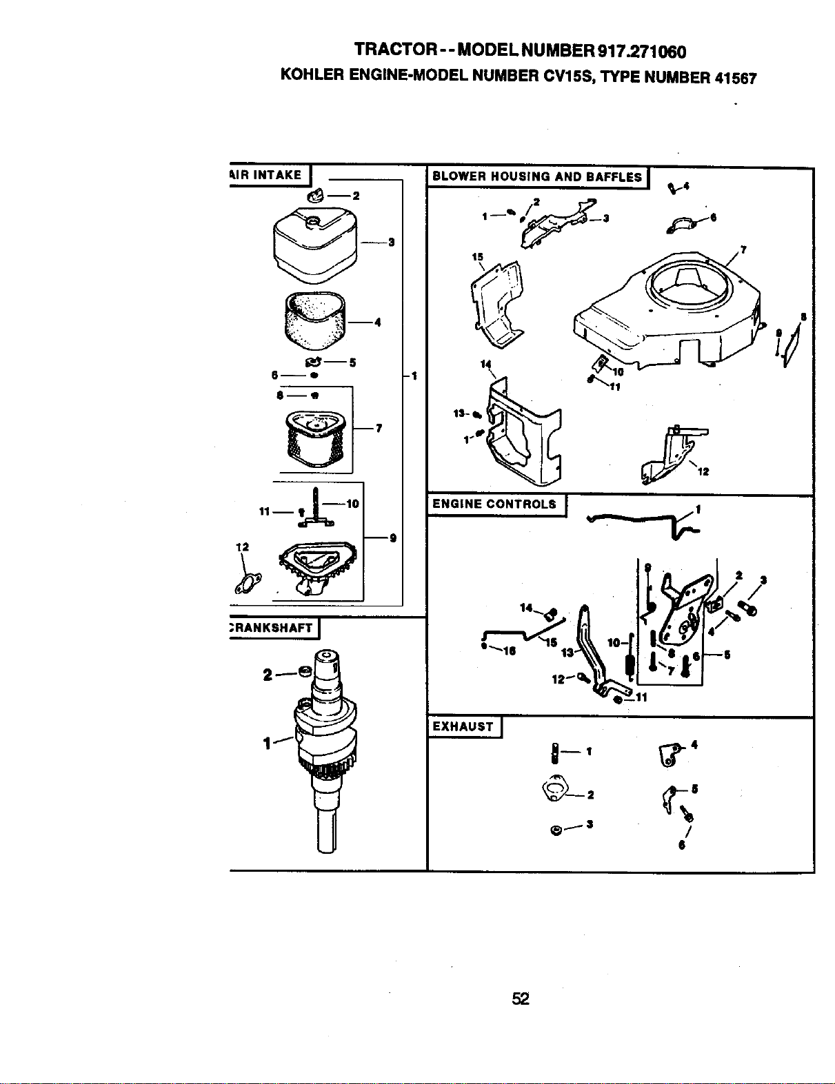
TRACTOR - - MODEL NUMBER 917.271060
KOHLER ENGINE-MODEL NUMBER CV15S, TYPE NUMBER 41567
L.IR INTAKE I
@-,
t;_--S
S--e
;RANKSHAFT I
-I
BLOWER HOUSING AND BAFFLES I
15
ENGINE CONTROLS I
__
/
S
?
52
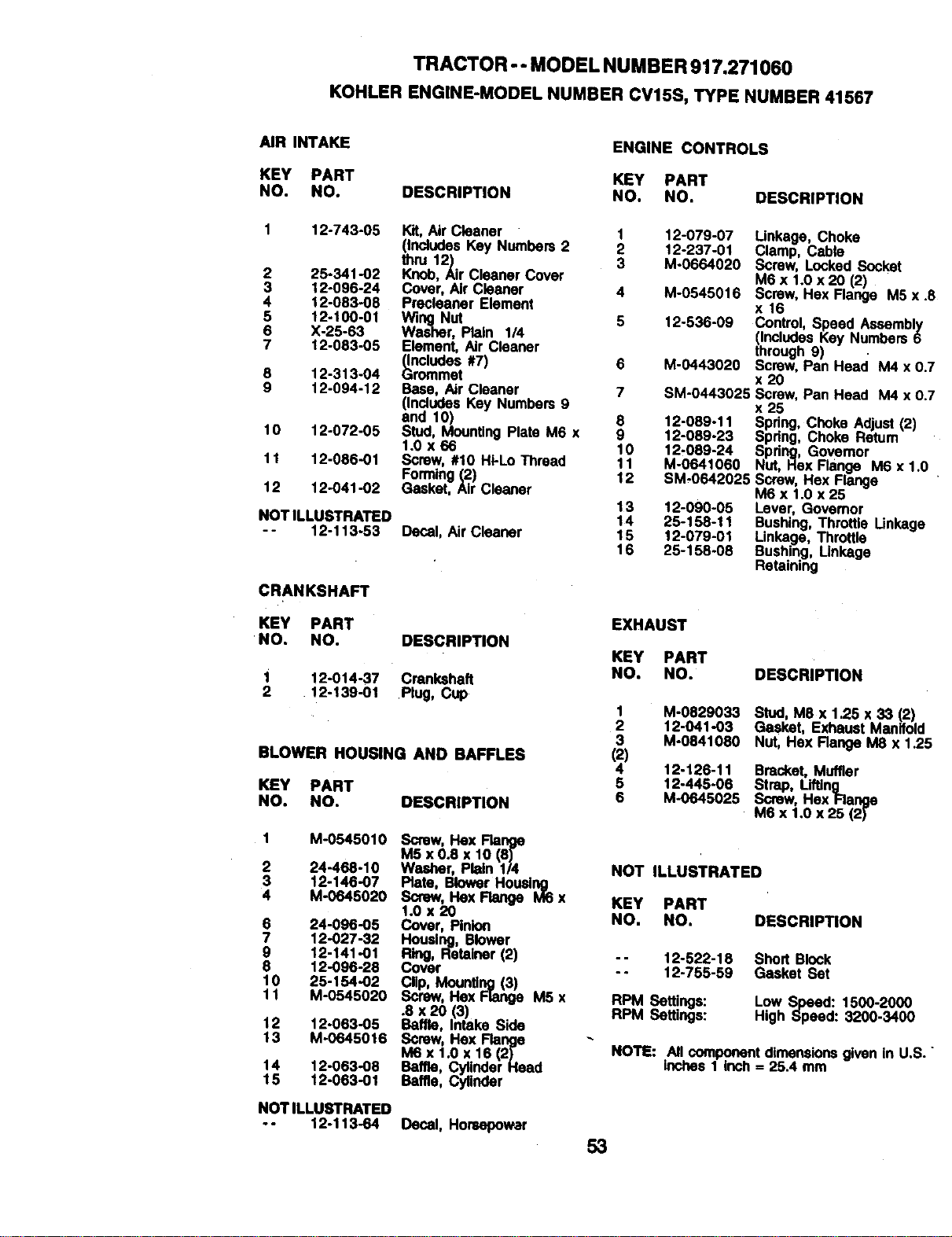
TRACTOR -- MODELNUMBER 917.271060
KOHLERENGINE-MODELNUMBERCV15S,TYPENUMBER41567
AIR INTAKE
KEY PART KEY PART
NO. NO. DESCRIPTION NO, NO,
1 12-743-05 Kit, AirCleaner 1
thrutnCludesKey Numbers 2 2
12) 3
2 25-341-02 Knob, Air Cleaner Cover
3 12-096-24 Cover, AirCleaner 4
4 12-083-08 Precleaner Element
5 12-100-01 Wing Nut 5
6 X-25-63 Washer, Plain 1/4
7 12-083-05 Element, Air Cleaner
(Includes #7) 6
8 12-313-04 Grommet
9 12-094-12 Base, Air Cleaner 7
(IncludesKey Numbers 9
end 10) 8
10 12-072-05 Stud, MountingPlate M6 x 9
1.0 x 66 10
11 12-086-01 Samw, #10 Hi-Lo Thread 11
Forming(2) 12
12 12-041-02 Gasket, Air Cleaner
13
NOT ILLUSTRATED 14
- - 12-113-53 Decal, Air Cleaner 15
16
CRANKSHAFT
KEY PART
NO. NO. DESCRIPTION
1 12-014-37 Crankshaft
2 12-139-01 Plug, Cup
BLOWER HOUSING AND BAFFLES
KEY PART
NO. NO. DESCRIPTION
1 M-0545010 Screw, Hex Flange
M5 x 0.8 x 10 (8)
2 24-468-10 Washer, Plain 1/4
3 12-146-07 Plate, Blower Housing
4 M-0645020 Screw, Hex Flange M6 x
1.0 x 20
6 24-096-05 Cover, Pinion
7 12-027-32 Housing, Blower
g 12-141-01 Ring, Retainer (2)
6 12-096-26 Cover
10 25-154-02 _NM_H:_
11 M-0545020 M5 x
.8 x 20 Inta(3)ka
12 12-063-05 Baffle,
Side
13 M-0645016 Screw, Hex Range
M6 x 1.0 x 16 (2)
14 12-063-08 Baffle, _r Heed
15 12-063-01 Baffle, Cylinder
NOT ILLUSTRATED
-- 12-113-64
Decal, Horsepower
ENGINE CONTROLS
DESCRIPTION
12-079-07 Linkage, Choke
12-237-01 Clamp, Cable
M-0664020 Screw, LockedSocket
M6 x 1.0 x 20 (2)
M-0545016 Screw, Hex Flange M5 x.
x16
12-536-09 Control,Speed Assembly
(IncludesKey Numbers6
through 9)
M-0443020 Screw, Pan Head M4 x 0
x 20
SM-0443025 Screw,Pan Heed MAx 0
x 25
12-089-11 Spdng,Choke Adjust (2)
12-089-23 Spdng, Choke Retum
12,089-24 Spdng, Governor
M-0641060 Nut,Hex Flange M6 x 1.0
SM-0642025 Screw, Hex Flange
M6 x 1.0 x25
12-090-05 Lever, Governor
25-158-11 Bushing,Throttle Linkage
12-079-01 Linkage, Throttle
25-158-08 Bushing, Linkage
Retaining
EXHAUST
KEY PART
NO. NO. DESCRIPTION
1 M-0829033 Stud,M8 x 1.25 x 33 (2)
2 12-041-03 Gasket, Exhaust Manifold
3 M-0841080 Nut, Hex Range M8 x 1.2:
42) 12-126-11 Bracket, Muffler
5 12-445-06 Strap, Lifting
6 M-0645025 Screw, Hex Flenge
M6 x 1.0 x 25 (2)
NOT ILLUSTRATED
KEY PART
NO. NO. DESCRIPTION
-- 12-522-18 Short Block
-- 12-755-59 Gasket Set
RPM Settings: Low Speed: 1500-2000
RPM Settings: High Speed: 3200-3400
NOTE: NI componentdimensionsgivenin U.S.
Inches 1 inch= 25.4 mm
53
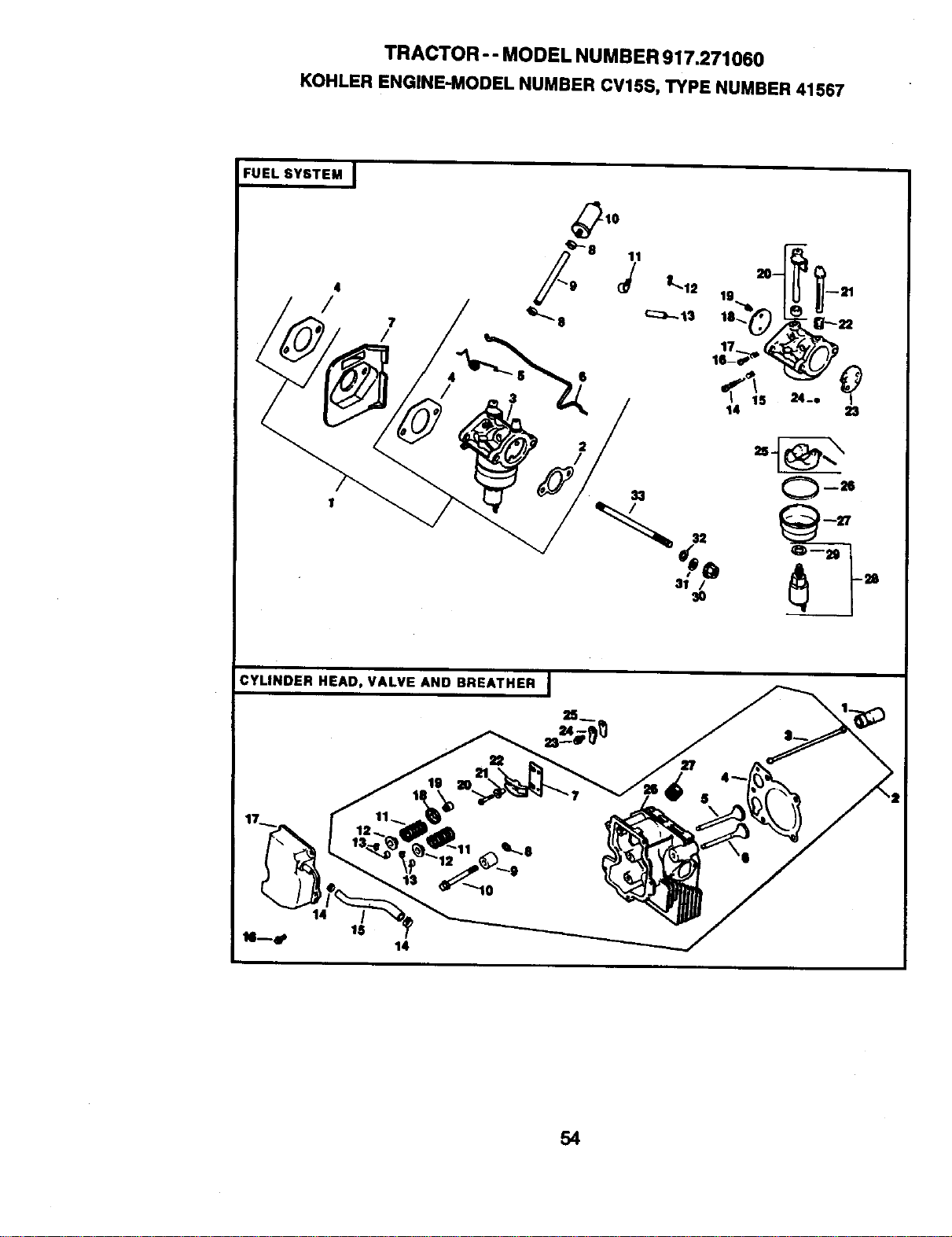
TRACTOR - - MODEL NUMBER 917.271060
KOHLER ENGINE-MODEL NUMBER CV15S,TYPE NUMBER 41567
FUEL SY6TEM I
4
/
/
31 /
CYLINDER HEAD, VALVE AND BREATHER
54
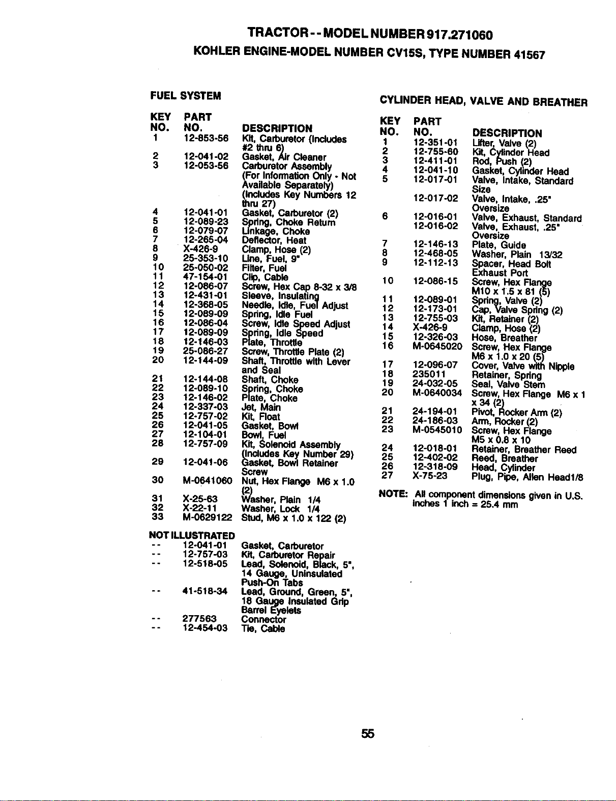
TRACTOR - -MODEL NUMBER 917.271060
KOHLERENGINE-MODELNUMBERCV15S,TYPENUMBER41567
FUEL SYSTEM
KEY PART
NO. NO.
1 12-853-56
2 12-041-02
3 12-053-56
4 12-041.01
5 12-089-23
6 12-079-07
7 12-265-04
8 X-426-9
9 25-353-10
10 25-050-02
11 47-154-01
12 12-086.07
13 12-431-01
14 12-368-05
15 12-089-09
16 12-086-04
17 12-089.09
18 12-146-03
19 25-086-27
20 12-144-09
21 12-144-08
22 12.069-10
23 12-146-02
24 12-337-03
25 12-757-02
26 12.041-05
27 12-104-01
28 12-757-06
29 12-041-06
30 M-0641060
31 X-25-63
32 X-22-11
33 M-0629122
NOT ILLUSTRATED
-- 12-041-01
- - 12-757-03
-. 12-518-05
- - 41-518-34
- - 277563
- - 12-454-03
CYUNDER HEAD, VALVE AND BREATHER
KEY PART
DESCRIPTION NO. NO.
Kit, Carburetor(Includes 1 12-351-01
#2 thru 6) 2 12-755-60
Gasket, Air Cleaner 3 12-411-01
CarburetorAssembly 4 12-041-10
(For InformationOnly. Hot 5 12.017-01
Available Separately)
(IncludesKey Numbers 12 12-017-02
thru 27)
Gasket, Carburstor(2) 6 12-016-01
Spdng, Choke Return 12-016-02
Linkage, Choke
Deflector, Heat 7 12-146-13
Clamp, Hose (2) 8 12-468-05
Line, Fuel, 9" 9 12-112-13
Filter, Fuel
Clip, Cable 10 12-086-15
Screw, Hex Cap 8-32 x 3/8
Sleeve, Insulating 11 12-089.01
Needle, Idle, Fuel Adjust 12 12-173-01
Spdng, Idle Fuel 13 12-755-03
Screw, Idle Speed Adjust 14 X-426-9
Spring, IdleSpeed 15 12-326-03
Plate, Throttle 16 M-0645020
Screw,ThrottlaPlate (2)
Shaft, Throttlewith Lever 17 12.096.07
and Seal 18 235011
Shaft, Choke 19 24-032-05
Spdng, Choke 20 M-0640034
Plate, Choke
Jet, Main 21 24-194-01
Kit, Float 22 24-186-03
Gasket, Bowl 23
Bowl, Fuel
Kit, Solenoid Assembly
(IncludesKey Number 29)
Gasket, Bowl Retainer
Screw
Nut, Has Flange M6 x 1.0
_1,-_asher,Plain 1/4
NOTE:
Washer, Lock 1/4
Stud, M6 x 1.0 x 122 (2)
Gasket, Carburetor
Kit, CarburetorRepair
Lead, Solenoid, Black, 5",
14 Gauge, Unineulated
Push-On Tabs
Lead, Ground, Green, 5",
18 Gauge InsulatedGdp
Barrel Eyelets
Connector
Tie, Cable
DESCRIPTION
Lifter,Valve(2)
Kit, CylinderHead
Rod, Push _2)
Gasket, CylinderHead
Valve, Intake, Standard
Size
Valve, Intake, .25"
Oversize
Valve, Exhaust, Standard
Valve, Exhaust, .25"
Oversize
Plate, Guide
Washer, Plain 13/32
Spacer, Head BOtt
xhaust Port
Screw, Hex Flange
M10 x 1.5 x 81 (5)
Spring, Valve (2)
Cap, Valve Spdng (2)
Kit, Retainer (2)
Clamp, Hose (2)
Hose, Breather
Screw, Hex Flange
M6 x 1.0 x 20 (5)
Cover, Valve with Nipple
Retainer, Spring
Seal, Valve Stem
Screw, Hex Flange M6 x 1
x34 (2)
Pivot, RockerArm (2)
Arm, Rocker(2)
M-0545010 Screw, Hex Flange
M5 x 0.8 x 10
24 12-018-01 Retainer, Breather Reed
25 12-402-02 Reed, Breather
26 12-316.09 Head, Cylinder
27 X-75-23 Plug, Pipe, Allen Heed1/8
Allcomponentdimensionsgiven in U.S.
inches1 inch= 25.4 mm
55
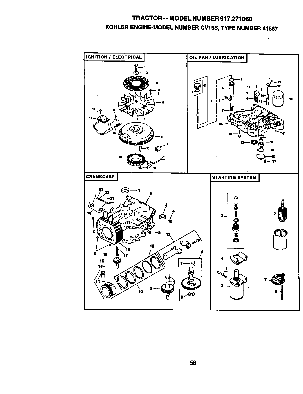
TRACTOR -- MODEL NUMBER 917.271060
KOHLERENGINE-MODELNUMBERCV15S,TYPENUMBER41567
IGNITION I ELECTRICAL I
_-,
_'_ ___,
OIL PAN I LUBRICATION J'
$.1
CRANKCASE I
STARTING SYSTEM I
'+ .d!
+.!
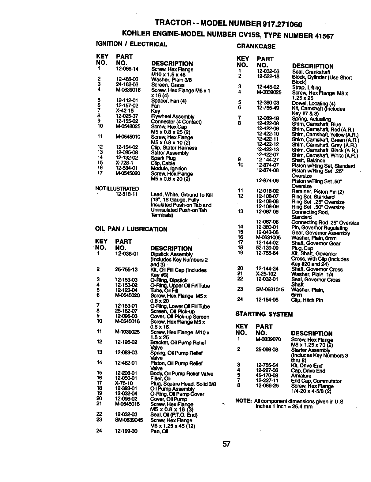
TRACTOR - - MODEL NU MBER 917.271060
KOHLER ENGINE-MODEL NUMBER CV15S, TYPE NUMBER 41567
IGNmON I ELECTRICAL CRANKCASE
KEY PART KEY PART
NO. NO. DESCRIPTION NO. NO.
1 12-086-14 Screw,Hex Flenge 1 12-032-03
M10x 1.5x46 2 12-522-18
2 12-468-03 Washer, Plain3/8
3 24-162-03 Screen, Grass 3 12-44502
4 M-0639016 Screw, Hex Flange M6 x I 4 M-0839025
x 16 (4)
5 12-112-01 Spacer, Fan (4) 5 12-38003
6 12-157-02 Fan 6 12-755-49
7 X-42-15 _h
8 12-025-37 eel Assembly 7 12-089-18
9 12-155-02 Connector (4 Contact) 8 12-422.08
10 M-(_48025 Screw,Hex Cap 12-422-09
M5 x 0.8 x 25 (2) 12-422-10
11 M-O545010 Scraw,Hex FlaNge 12-422-11
M5 x 0.8 x 10 (2) 12-422-12
12 12-154-02 Clip, StatorHarness 12-422-13
13 12-085-08 Stator Asssmbly 12-422-07
14 12-132-02 Spad_Ptug 9 12-144-27
15 X-728-1 Clip,Cable 10 12-874-07
16 12-584-01 Module, Ignition 12-874.08
17 M-0545020 Screw,HexRange
M5 x 0.8 x 20 (2) 12-874-09
NOTILLUSTRA'I_D 11 12-018-02
-- 12-518-11 Leed,Whlta, GroundToKill 12 12-10e-07
19", 18 Gauge, Fully 12-108-06
nsuistedPush-onTab and 12-10609
UnlnsulatedPush-onTab 13 _,2-067-05
Termioais)
12-067-06
14 12-380-01
OIL PAN I LUBRICATION 15 12-043-05
16 M-0631005
KEY PART 17 12-144-02
NO. NO. DESCRIPTION 18 52-139-09
1 12-038-01 DipstickAssembly 19 12-755-64
(includesKey Numbers2
and3)
2 25-755-13 Kit, Oil FillCap (Includes 20 12-144-24
Key #3) 21 X-25-102
3 12-153-O3 O-Ring, _itck 22 12-032-01
4 12-153-02 O-Ring,Upperoil FBTube
5 12-123-04 Tube,Oil Fill 23 SM-0631015
6 _ Screw, Hex Ftange M5x 24 12-15405
0.8x 20
7 12-153-01 O-Ring, LowerOilFillTube
8 25-162-07 Screen, oil Pisk-up STARTING SYSTEM
9 12-096.03 Cover, Oil Pick-upScreen
I0 M.0545016 Screw,Hex Range M5 x
0.8 x 16 KEY PART
11 M-10390L)5 Screw,Hex Range Ml0x NO. NO;
1.5 x 25 1 M-0839070
12 12-126-02 Bracket,Oil Pump Relief
Valve 2 25-096-03
13 12"089-03 vaSPalvdnge,oil Pump Rellef
14 12_-01 Piston,oil Pump Relief 3 12-755-54
Valve 4 12-227-06
15 12-208-01 Body,Oil PumpRelief Valve 5 45-170-0_
16 12-050-O1 Filler,Oil 7 12-227-I I
17 )(-75-10 Plug,Sque,re Head, Sotid3/8 8 12.086-25
18 12-3,93-01 OIIPumpAssemb_/
19 12-032.04 O-Ring,OilPumpLover
20 12-09602 Cover, OilPump
21 M-0545016 Screw, HexRange "_
M5 x 0.8 x 16 (3)
22 12-032-03 Seal, Oil(P.T.O.End)
23 SM-0e39045 Screw,l-laxFlange
M8 x 1.25 x 45 (12)
24 12-199-30 Pan,Oil
DESCRIPTION
Seal, Crankshaft
Block,Cylinder(Use Short
Block)
strop,
Screw, Hex Hange M8 x
1.25 x 25
Dowel,Locating(4)
Kit,Camshaft 0nclodes
Key #7 &8)
Spring,Actuating
Shim,Camshaft, B4uo
Shim,Camshaft, Red (A.R.)
Shim,Camshaft,Yellow(A.R.)
Shim,Camshaft, Greee (A.R.)
Shim,Camshaft, Grey (A.R.)
Shim,Camshaft, Black(A.R.)
Shim,Camshaft,White(A.R.)
Shaft, Balance
Pistonw/Ring Set, Standard
Pistonw/Ring Set .25'
Oversize
Pistonw/Ring Set .50"
Oversize
Retainer, PistonPin(2)
Ring Set, Standard
RingSet .25" Oversize
RingSet .50" Oversize
ConnectingRod,
Standard
ConnectingRod .25"Oversize
Pin,GovernorRegulating
Gear,Govemor Aseembly
Washer, Plain,6mm
Shaft, Govemor Gear
Plug,Cup
Kit, Shaft, Governor
Cross,withClip (Includes
Key #20 and 24)
Shaft, GovernorCross
Washer, Plain 1/4
Seal, GovernorCross
Shaft
Washer, Plain,
6turn
Clip,Hitch Pin
DESCRIPTION
Screw,HexRange
¥8 x 1.25x70 (2)
_'_rtarAssembly
(IndudeeKeyNumbers3
thru8)
I_, DriveEnd
Cap/uCa_ma,DdveEnd
tura
EndCap,Commutator
Screw,HexF_nga
114-20x 4-5/8(2)
NOTE: AIIcomponent dimensionsgivenin U.S.
inches 1inch = 25.4 mm
57

58

SUGGESTED GUIDE FOR SIGHTING SLOPES FOR SAFE OPERATION
I "
SIGHTING
ONLY RIDE UP AND DOWN HILL,
NOT ACROSS HILL
I
Operate your Tractor up and down the face of slopes (not l
greater than 15°), never across the face. Make rums gradu-
I
ally to prevent tlpplng or loss of control. Exercise extreme
caution when changing dlrectlon on slopes.

For in-home major brand repair service:
Call 24 hours a day, 7 days a week
1-800-4-MY-HOME s" (1-800-469-4663)
Para pedir servicio de reparaci6n a domicilio
1-800-676-5811
In Canada for all your service and parts needs call
Au Canada pour tout le service ou les pi6ces
1-600-665-4455
For the repair or replacement parts you need:
Call 6 am - 11 pm CST, 7 days a week
PartsDirects"
1-800-366-PART (1-800-366-7278)
Para ordenar piezas con entrega a domicilio
1-600-659-7084
For the location of a Sears Parts and Repair Center
in your area:
Call 24 hours a day, 7 days a week
1-800488-1222
For Information on purchasing a Sears Maintenance
Agreement or to inquire about an existing Agreement:
Call 9 am - 5 pm, Monday - Saturday
1-800-827-6655
pr
SEARS
Home Central°"
172210 11.19.99 RD Printed in U.S.A.