12500
EN
Original Instructions
Version 1 – May 2023
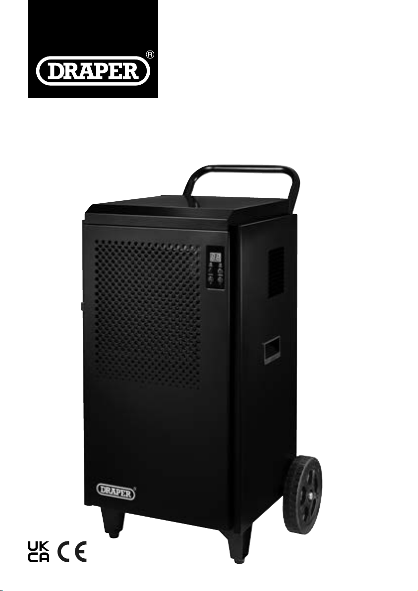
70L
DEHUMIDIFIER
1.1 Product Reference
User Manual for: Industrial Dehumidier, 70L
Stock No: 12500
Part No: DH70
1.2 Revisions
Version 1: May 2023
First release
As our manuals are continually updated, always ensure
that the latest version is used.
Please visit drapertools.com/manuals for the latest
version of this manual and the associated parts list, if
applicable.
1.3 Understanding the Safety Content of
This Manual
WARNING!
– Situations or actions that may result
in personal injury or death.
CAUTION! – Situations or actions that may result
in damage to the product or surroundings.
Important: – Information or instructions of particular
importance.
1.4 Copyright © Notice
Copyright © Draper Tools Limited.
Permission is granted to reproduce this manual for
personal and educational use ONLY. Commercial
copying, redistribution, hiring or lending is strictly
prohibited.
No part of this manual may be stored in a retrieval system
or transmitted in any other form or means without written
permission from Draper Tools Limited.
In all cases, this copyright notice must remain intact.
1. Preface
– 2 –
These are the original product instructions. This
document is part of the product; retain it for the life
of the product, passing it on to subsequent holders.
Read this manual in full before attempting to
assemble, operate or maintain this product.
This Draper Tools manual describes the purpose
of the product and contains all the necessary
information to ensure its correct and safe use.
Following all the instructions and guidance in
this manual will ensure the safety of both the
product and the operator and increase the
lifespan of the product.
All photographs and drawings within this manual are
supplied by Draper Tools to help illustrate correct
operation of the product.
Every eort has been made to ensure the
information contained in this manual is accurate.
However, Draper Tools reserves the right to amend
this document without prior warning. Always use the
latest version of the product manual.

2. Contents
– 3 –
EN
1. Preface 2
1.1 Product Reference 2
1.2 Revisions 2
1.3 Understanding the Safety Content of This
Manual 2
1.4 Copyright © Notice 2
2. Contents 3
3. Product Introduction 4
3.1 Intended Use 4
3.2 Specication 4
4. Health and Safety Information 5
4.1 Health and Safety Information for this
Dehumidier 5
4.2 Additional Safety Information for
Flammable Refrigerants 6
4.3 Connection to the Power Supply 7
4.4 Residual Risk 7
5. Identication and Unpacking 8
5.1 Product Overview 8
5.2 What’s in the Box? 9
5.3 Packaging 9
6. Preparation Instructions 10
6.1 Assembling the Dehumidier 10
6.2 Positioning the Dehumidier 11
7. Operating Instructions 12
7.1 The Control Panel 12
7.2 Switching the Dehumidier
On and O 12
7.3 Continuous Drainage 12
7.4 Setting the Target Humidity 13
7.5 Using the Timer 13
7.6 Auto-Defrost Functionality 13
7.7 Overheating Protection 13
8. Maintenance and Troubleshooting 14
8.1 General Maintenance and Storage 14
8.2 Air Filter Care 14
8.3 Air Inlet Care 14
8.4 Troubleshooting 15
9. Spares, Returns and Disposal 17
10. Warranty 18
11. Explanation of Symbols 19

3. Product Introduction
– 4 –
3.1 Intended Use
This product is designed to extract moisture from damp
or humid industrial environments to prevent the build-up
of mould and other hazards. Any other application
beyond the conditions established for use will be
considered misuse. Draper Tools accepts no
responsibility for improper use of this product.
Part of our ore range, this product is suitable for regular
use by enthusiasts and tradespersons alike.
Important: This product is not a water pump and is not
designed to transfer water from one location to another.
WARNING! This product is not a toy and must be
respected.
Read this manual in full before attempting to assemble,
operate or maintain the product, and retain it for later
use.
Stock No. 12500
Part No. DH70
Rated voltage 220–240V AC
Rated frequency 50Hz
Rated power 1
Rated current 5.7A
Extraction rate 70L per day (at 30°C, 80% relative humidity)
Target humidity range 10–95%
Discharge hose length 90cm
Discharge hose outlet Ø16mm
Refrigerant R290 (propane), 280g
Max. suction pressure 1.0Mpa
Max. discharge pressure 2.5Mpa
Minimum room size 14m
2
Ambient operation environment 5–35°C
Global warming potential 3
Ingress protection IP22
Dimensions W 545 × H 870 × D 580mm
Net weight 40kg
Dimensions W 450 × H 655 × D 480mm
Net weight 30kg
3.2 Specication

4. Health and Safety Information
Important: Read all the Health and Safety instructions
before attempting to assemble, adjust, operate or
maintain this product. Non-compliance with these
instructions may result in injury or damage to the user or
the product.
4.1 Health and Safety Information for this
Dehumidier
General Safety Instructions
• Only authorised personnel that have been trained in
the use of this product and are familiar with the
instructions in this manual may operate this machine.
Important: This product is not suitable for use by
children.
• Inspect the product before every use for cracked,
corroded or broken parts and leakages.
WARNING! DO NOT use this product if it is
damaged or leaking in any way. Contact Draper
Tools for repair and replacement options.
• Use this product only for its intended purpose and do
not modify it in any way.
• DO NOT operate this product while tired or under the
inuence or alcohol, drugs or other medication.
• Keep your hands and other body parts away from
moving parts at all times and keep loose hair, clothing
and jewellery tied back.
• ONLY use spare parts supplied by Draper Tools.
Installation
• DO NOT use or store this product in unventilated
areas that are smaller than the minimum required
space for this product.
• DO NOT use this product in environments containing
high concentrations of dust; ammable, volatile, toxic
or otherwise dangerous gases, vapours and liquids; or
where the air composition is ammable.
• DO NOT use this product in locations in which ames
or sources of ignition are present.
• This product is suitable for indoor use ONLY; DO NOT
immerse it in water or expose it to wet conditions.
• DO NOT use this product in the vicinity of water tanks.
• Keep all air vents and grilles free from obstructions.
• Use this product ONLY on sturdy, at and level
surfaces capable of bearing the weight of the product.
Important: DO NOT use this product on tilted
surfaces as it may cause damage to the internal
components or cause the unit to tip over.
• Ensure that the product is positioned with no less than
the minimum clearance required around all sides of
the unit during use.
• DO NOT place the product directly beneath wet
materials; allow at least one metre between the unit
and the items to be dried.
• Ensure that the discharge hose is placed tidily and
does not create a trip hazard.
• DO NOT submerge the end of the discharge pipe as
this may cause moisture to be drawn back into the
dehumidier.
Correct Use and Operational Safety
• NEVER connect this product to a power supply if the
air lter is not installed.
• NEVER cover the air vents and grilles or place any
object on the product during use.
• DO NOT insert foreign objects through the air vents or
grilles.
• NEVER open or place your hands inside the product
during use.
• ALWAYS switch o the product using the power
button before disconnecting the power supply.
Electrical Safety
• Keep the power cord away from sources of heat,
liquids, oil and hot or sharp surfaces.
• NEVER handle the plug or operate the product with
wet hands.
• NEVER pull the product along using the power cable
or plug and DO NOT pull on the cable to disconnect
the plug from a power supply.
• Position the power cable tidily and safely so that it
does not create a trip hazard.
– 5 –
EN
4. Health and Safety Information
Handling and Storage
WARNING! This product is heavy and requires
two people to lift and transport it. Use
appropriate equipment where necessary. Failure
to transport the product safely may result in
serious injury.
• Switch o the product, disconnect it from the power
supply and wait for all moving parts to stop before
attempting to maintain or move the unit.
• Store and transport the product in an upright
position.
• DO NOT use or store this product in the presence of
ammable liquids or vapours.
• Discard any liquid extracted by the product; DO NOT
use it for any other purpose.
Servicing
• Any maintenance beyond the procedures detailed in
this manual MUST be performed by an authorised
and suitably qualied technician.
4.2 Additional Safety Information for
Flammable Refrigerants
WARNING! This product contains approximately
200g of pressurised R290 (propane) refrigerant.
This substance is highly ammable and must
NOT be exposed to sources of ignition.
• DO NOT use this product in spaces that are smaller
than the minimum room size rated for the unit.
• By means of ventilation or construction, the space in
which the unit is installed must NOT cause or allow
the refrigerant to stagnate and create a re or
explosion hazard in the event of a leak.
• The unit MUST be stored in a well-ventilated room no
smaller than the minimum room size required for
operation in which no continuously operating open
ames (e.g. an operating gas appliance) and no
sources of ignition (e.g. an operating electric heater)
are present.
• Keep all air vents and grilles in the location and on the
product free from obstructions.
• DO NOT attempt to undertake any maintenance
procedures not covered in this manual; additional
servicing and handling of the refrigerant MUST be
conducted by an authorised and suitably qualied
service agent who is competent in the use and
handling of ammable refrigerants.
• DO NOT puncture, burn or attempt to modify the
refrigerant system or its components in any way.
• DO NOT use any means to accelerate the defrosting
process or to clean other than those identied in this
manual.
WARNING! Refrigerant gases may be odourless
and can explode in the presence of sources of
heat and ignition.
– 6 –
4. Health and Safety Information
4.3 Connection to the Power Supply
WARNING! Risk of electric shock. DO NOT open
this product.
This appliance is supplied with an approved plug and
cable for your safety. The product must be installed
according to national wiring regulations.
If the power supply cord is damaged, it must be replaced
by Draper Tools, an authorised service agent or similarly
qualied personnel in order to avoid a hazard.
The damaged or incomplete plug, when cut from the
cable, must be disabled to prevent connection to a live
electrical outlet.
This product is Class I* and is designed for connection
ONLY to a power supply matching that detailed on the
rating label and compatible with the plug tted.
The value of the fuse tted is marked on the pin face of
the plug. Should the fuse need replacing, ensure the
substitute is of the correct rating, approved to BS 1363/A
and ASTA or BS Kite marked. This should only be
performed by suitably qualied personnel.
ASTA
BSI
The fuse can be replaced by removing the cover using a
small plain slot screwdriver and removing the broken
fuse from its holder. This should only be performed by
suitably qualied personnel.
If an extension lead is required, use an approved and
compatible lead rated for this appliance. Where use of an
extension lead is unavoidable, Draper Tools recommends
using a 2.5mm cable. Follow all the instructions supplied
with the extension lead.
Important: Always follow the extension lead instructions
regarding maximum load while the cable is wound. If in
doubt, unwind the entire cable. A coiled extension lead
generates heat which could melt the lead and cause a
re.
*Earthed: This product requires an earth connection to
protect against electric shock from accessible
conductive parts in the event of a failure of the basic
insulation.
4.4 Residual Risk
The safety instructions in this manual cannot account for
all possible conditions and situations that may occur.
Exercise common sense and caution when using this
product and protect against any additional conceivable
risks.
– 7 –
EN
– 8 –
5. Identication and Unpacking
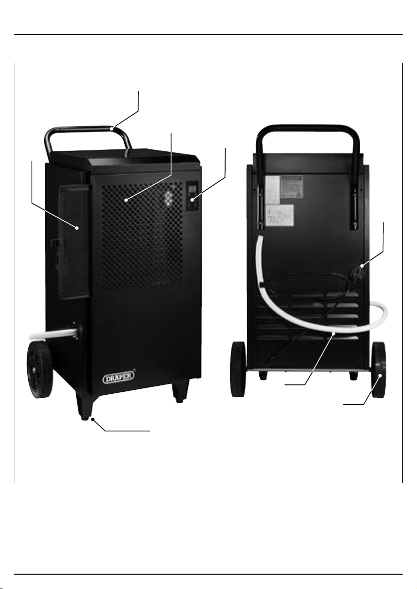
5.1 Product Overview
(1) Air lter
(2) Air inlet
(3) Control panel
(4) Discharge hose
(5) Front feet
(6) Power cable and plug
(7) Transport handle
(8) Wheels
(1)
(2)
(7)
(3)
(6)
(4)
(8)
(5)
– 9 –
5. Identication and Unpacking
5.3 Packaging
Keep the product packaging for the duration of the
warranty period for reference should the product need to
be returned for repair.
WARNING! Keep packaging materials out of
reach of children. Dispose of packaging
correctly and responsibly and in accordance
with local regulations.
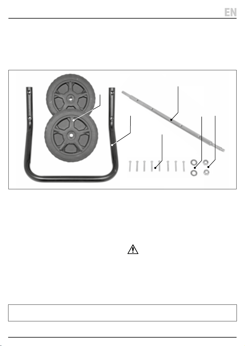
(A) 1 × Dehumidier unit (not shown)
(B) 1 × Transport handle
(C) 1 × Axle
(D) 2 × Wheels
(E) 8 × M6 × 35mm bolts
(F) 2 × M12 washers
(G) 2 × M12 nuts
Please visit drapertools.com for our full range of accessories and consumables.
– 9 –
EN
5.2 What’s in the Box?
Carefully remove the product from the packaging and
examine it for any signs of damage that may have
occurred during shipment.
Before assembling the product, lay the contents out and
check them against the parts shown below. If any part is
damaged or missing, do not attempt to use the product.
Please contact the Draper Helpline; contact details can
be found at the back of this manual.
(D)
(B)
(G)
(F)
(E)
(C)
6. Preparation Instructions
Important: Before assembling and installing this
product, read and understand all the safety instructions
listed in this manual.
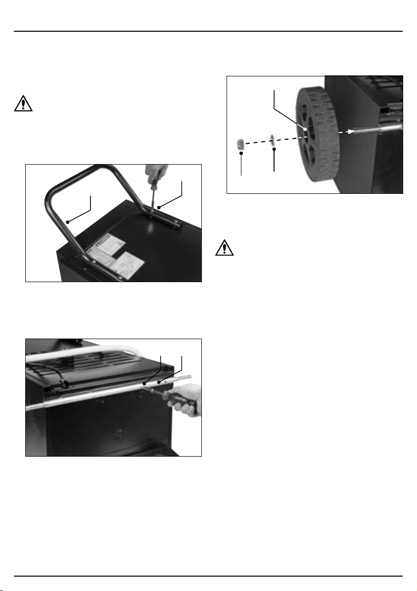
6.1 Assembling the Dehumidier
WARNING! This product is heavy. For your
safety, Draper Tools recommends that this
product is assembled by two people.
1. Align the transport handle (B) with the back of the
unit and secure it in place using four M6 × 35mm
bolts (E).
1 Fig.
(E)
(B)
2. Carefully tip the dehumidier unit onto its front face.
3. Align the axle (C) with the base of the unit and secure
it in place using four M6 × 35mm bolts (E).
2 Fig.
(C)(E)
4. Place a wheel (D) onto each end of the axle and
secure them in place using the M12 washers (F) and
M12 nuts (G).
3 Fig.
(D)
(G)
(F)
Important: DO NOT overtighten the wheel nuts.
5. Carefully tip the unit into its upright position.
CAUTION! After assembly or tipping the
dehumidier for any reason, allow it to rest in an
upright position for at least 2 HOURS before
connecting it to mains power.
– 10 –
6. Preparation Instructions
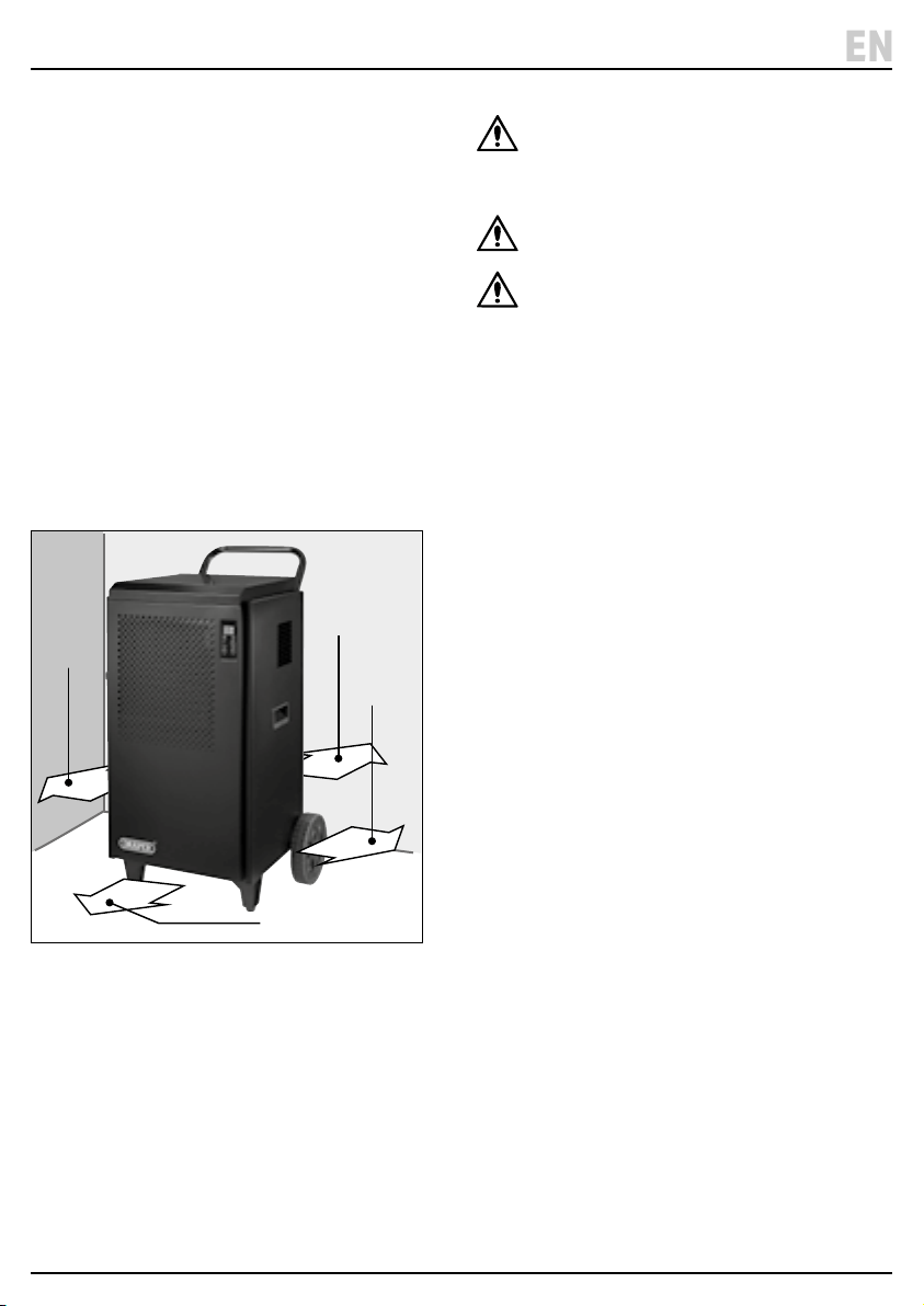
6.2 Positioning the Dehumidier
Failure to position the dehumidier correctly will
adversely impact on its performance.
• Allow at least 50cm of clear space around the sides
and rear of the unit.
• Allow at least 1m of clear space at the front of the unit.
• Position the unit in a clear and central location.
• For maximum eciency, create an enclosed
environment by closing all doors and windows.
Important: The enclosed area MUST be larger than
the minimum room size rated for the unit.
• When used in a home, ensure that all external
openings are closed and open all appropriate interior
doors, with the unit located in a central location.
• If moisture or dampness is particularly prolic in one
specic area, position the unit closer to that location
before moving to a more central spot.
4 Fig.
≥ 50cm
≥ 50cm
≥ 1m
≥ 50cm
WARNING! Position the unit on sturdy at and
level surfaces ONLY. NEVER position the unit on
sloped surfaces as it may tip over and cause
injury or damage.
CAUTION! DO NOT position the unit in close
proximity to radiators or other heat sources.
CAUTION! When using the dehumidier to dry
wet materials, position the unit at least one
meter from the items to be dried. This prevents
water from falling onto the unit and damaging
internal components.
– 11 –
EN
Important: Ensure that the product is correctly prepared
and positioned before operation.
CAUTION! After assembly or tipping the
dehumidier for any reason, allow it to rest in an
upright position for at least 2 HOURS before
connecting it to mains power and switching it
on.
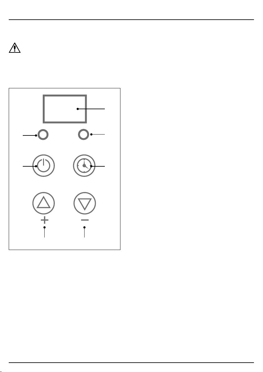
7.1 The Control Panel
5 Fig.
(11) (9)
ON/OFF
POWER
TIMING
8.8.
TIMER
(12)
(13)
(14)
(15)
(10)
(9) Decrease value button
(10) Display screen
(11) Increase value button
(12) Power button
(13) Power indicator
(14) Timer button
(15) Timer indicator
7.2 Switching the Dehumidier
On and O
Important: ALWAYS ensure that the air lter (1) is
installed and that the discharge hose (4) is positioned
correctly before switching on the product.
To switch the dehumidier on, ensure that it is positioned
correctly with suitable clear space around each side of
the unit, then connect the plug (6) to a power supply.
While the dehumidier is connected to mains power but
not switched on, it remains in standby mode. To switch
on the unit, press the power button (12) once. Press the
power button again to return the unit to standby mode.
To completely shut down the unit, disconnect the plug
from mains power.
Important: The fan continues to operate for a few
seconds after the unit is switched o.
Important: ALWAYS switch o the unit using the power
button BEFORE disconnecting the plug from the power
supply.
7.3 Continuous Drainage
This product in not tted with an internal water tank and
does not store moisture extracted from the space.
Instead, a Ø16 × 90mm discharge hose is tted directly
to the unit to allow for continuous drainage.
Draper Tools recommends locating the discharge point
in a permanent drain or closed-top container to prevent
the moisture from being recycled through the
dehumidier once it has been discharged.
Important: The discharge point of the hose MUST be
lower than the water tank outlet in order for water to be
continually discharged from the unit. Ensure that the
hose is not bent or kinked and does not contain any
upward stretches.
Important: Ensure that the receptacle is large enough to
accommodate the amount of moisture that will be
extracted during the operating time. The product will
NOT stop operating if the receptacle is lled.
This product may be used with an external uplift pump
(not supplied) for low-level applications.
Important: Ensure that the water discharged from the
hose does not create a slipping hazard.
– 12 –
7. Operating Instructions

7. Operating Instructions
7.4 Setting the Target Humidity
The target humidity of the room to be treated can be set
from 10–95%. To set the target humidity level, press the
increase (11) and decrease (9) value buttons as
appropriate while the device is switched on. The display
screen (10) displays the chosen percentage. When the
desired level is reached, allow the display to stop ashing
to save the target value.
Once a target humidity value has been set, the
dehumidier will run until that level has been reached. If
the humidity level rises by 3% above the set level, the
unit will automatically resume operation until the
congured level is reached again.
The recommended target humidity for a typical room is
50–70%.
Important: If the target humidity level is set at a value
lower than is achievable in the climate in which it is used,
the dehumidier will operate continuously.
7.5 Using the Timer
The dehumidier can be programmed to switch either on
or o after a dened number of hours. If a value is set for
both on and o timers, the unit will cycle between on and
o according to the congured intervals.
To enable the timer, press the timer button (14) and use
the increase (11) and decrease (9) value buttons to set
the number of hours until the unit switches on or o. The
chosen value is shown on the display screen (10). When
the desired number of hours is reached, allow the display
to stop ashing to save the target value.
If the timer is set while the unit is in standby mode, the
timer will determine the number of hours until the
dehumidier automatically switches on.
If the timer is set while the unit is switched on, the timer
will determine the number of hours until the dehumidier
automatically switches o (unless the water tank is lled
before this period expires).
7.6 Auto-Defrost Functionality
When used for extended periods or in lower ambient
temperatures, frost may accumulate on the evaporator
coils, reducing the airow within the unit. When this
occurs, the dehumidier will automatically enter Defrost
mode.
When Defrost mode is enabled, the compressor switches
o but the fan continues to run.
When the dehumidier has completed the defrosting
process, it will automatically resume operation with the
previously congured settings.
Important: DO NOT switch o the machine or
disconnect it from mains power during defrosting.
7.7 Overheating Protection
The dehumidier is tted with overload and overheating
protection functions
If sudden power loss to the unit occurs during operation,
the unit will shut down for three minutes to protect the
compressor and will not run during this period. If power
is reconnected, the dehumidier will resume operation
once this time has elapsed.
If the temperature of the coolant circuit coil rises
abnormally and does not drop within 10 minutes, the
unit will enter standby mode. The dehumidier will not
operate until the circuit has cooled.
– 13 –
EN
– 14 –
8. Maintenance and Troubleshooting
Important: ALWAYS switch o and disconnect the
dehumidier from the power supply, allow moving parts
to stop and empty the water tank before performing any
product care or maintenance.
8.1 General Maintenance and Storage
• Clean the outer surface of the unit with a soft, damp
cloth and mild detergent.
− DO NOT spray the device with liquid or submerge
it in water.
− Once clean, wipe the unit dry to prevent corrosion.
CAUTION! DO NOT use solvents or
aggressive chemicals to clean the unit as
they may cause corrosion or damage
insulated parts.
• Clean other parts of the unit in accordance with their
dedicated instructions.
• Inspection and replenishment of the coolant MUST
be performed by an authorised and qualied service
agent.
• Disconnect the plug from the power supply when the
unit is not used for extended periods.
• Store the product upright in a cool, clean and dry
environment, out of direct sunlight and out of reach of
children.
• Store the unit in a well-ventilated room no smaller
than the minimum room size required for operation in
which no continuously operating open ames (e.g. an
operating gas appliance) and no sources of ignition
(e.g. an operating electric heater) are present.
• Observe any additional storage safety instructions
relating to R290 refrigerant; see 4.2 Additional
Safety Information for Flammable Refrigerants.
8.2 Air Filter Care
Over time, the air lter (1) will gather dust and debris
from the air drawn into the dehumidier. Clean the lter
regularly to ensure a consistent ow of air into the unit.
6 Fig.
(1)
1. Pull the air lter out of the front of the unit and tap
away any excess dust.
2. Remove light dust using a vacuum cleaner and a soft
brush.
3. For tough dust or clogged lters, wash the lter
element in hot, soapy water and allow it to dry
naturally and thoroughly.
4. Insert the lter back into the unit.
CAUTION! NEVER connect the dehumidier to a
power supply or switch it on without the air
lter installed.
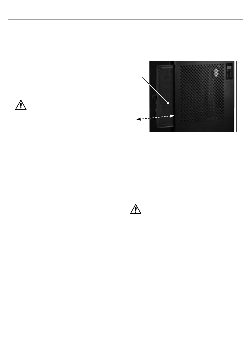
8.3 Air Inlet Care
The air inlet (2) grille may accumulate dust and other
debris during operation. Clean the inlet grille regularly to
ensure a consistent ow of air into the unit.
To clean the inlet grille, remove the air lter (1) from the
unit and use a vacuum cleaner or compressed air at low
pressure and a soft brush.

8. Maintenance and Troubleshooting
– 15 –
8.4 Troubleshooting
Problem Possible cause Remedy
The unit expels hot or cold air. Normal operation. During normal operation, cold air is
expelled from the machine. Hot air is
produced during the defrost cycle.
The unit does not switch on. The product is not connected to an
active power supply.
Check that the plug is securely
connected and that the power supply
is active.
The ambient temperature is beyond
the working range of the unit.
Take steps to bring the ambient
temperature within 5–35°C.
The unit is defrosting. Wait for defrosting to complete before
resuming. Increasing the ambient
temperature may help to speed up the
defrosting process.
The power supply was interrupted. Wait for three minutes for the overload
protection to deactivate.
The unit does not extract much
moisture.
The air lter or air inlet is clogged. Clean the inlet grille and lter element
as appropriate.
The ambient temperature and/or
humidity are already low.
The unit is operating normally.
The target humidity level is greater
than the current ambient humidity
level.
Reduce the target humidity level until
it is lower than the current level.
Water is leaking from the unit. The discharge hose is damaged,
obstructed or poorly connected to the
water tank outlet.
Check the hose connection and
inspect it for any damage, cracks,
kinks or blockages.
The device is excessively noisy. The device is not stable or the surface
is not level.
Move the unit to a more appropriate
location. Empty the water tank and
switch o the unit before moving it.
An internal component has become
loose.
Have the unit inspected and repaired
by an authorised service agent.
The noise sounds like water owing. This is normal and is caused by the
coolant circulating.
EN

8. Maintenance and Troubleshooting
8.4 Troubleshooting (continued)
Problem Possible cause Remedy
The control panel displays an error
code.
E1 – Coolant coil sensor fault. Ensure that the environment meets
the requirements for this unit. Unplug
the unit and allow it to rest for several
minutes before retrying. If the error
persists, contact Draper Tools for
support.
E2 – Moisture sensor error.
E3 – Temperature sensor error.
EE – Coolant leak. Switch o and unplug the unit and
ensure that the room is well-
ventilated. Allow the unit to rest for at
least three hours before retrying. If the
error persists, contact Draper Tools for
support.
– 16 –
– 17 –
For spare parts, servicing, and repair and replacement
options, please contact the Draper Tools Product
Helpline for details of your nearest authorised agent.
Draper Tools will endeavour to hold any spare parts, if
applicable, for seven years from the date that it sells the
nal matching stock item.
Any servicing or repairs carried out by unauthorised
personnel or installation of spare parts not supplied by
Draper Tools will invalidate your warranty.
Important: For safety, ALWAYS drain and clean the
product of any oil, fuel, chemicals or other substances
before returning it to Draper Tools or its authorised
agent. Store these materials in suitable containers and
dispose of them in accordance with local regulations.
Draper Tools and its agents cannot be responsible for the
disposal of these substances.
At the end of its working life, dispose of the product
responsibly and in line with local regulations. Recycle
where possible.
• DO NOT dispose of this product with domestic waste;
most local authorities provide appropriate recycling
facilities.
• DO NOT burn or incinerate this product.
• DO NOT abandon this product in the environment.
9. Spares, Returns and Disposal
EN

10. Warranty
Draper Tools products are carefully tested and inspected
before shipment and are guaranteed to be free from
defective materials and workmanship.
Should the tool develop a fault, return the complete tool
to your nearest distributor or contact Draper Tools
directly. Contact information can be found at the back of
this manual.
Proof of purchase must be provided.
If, upon inspection, it is found that the fault occurring is
due to defective materials or workmanship, repairs will
be carried out free of charge. This warranty period covers
parts and labour for 12 months from the date of
purchase. Where tools have been hired out, the warranty
period covers 90 days from the date of purchase.
This warranty does not apply to any consumable parts,
batteries or normal wear and tear, nor does it cover any
damage caused by misuse, careless or unsafe handling,
alterations, accidents, or repairs attempted or made by
any personnel other than the authorised Draper Tools
repair agent.
In all cases, to make a claim for faulty workmanship or
materials within the standard warranty period, please
contact or return the product to the place of purchase.
Proof of purchase may be required.
If the place of purchase is no longer trading or if you
experience any diculties with your warranty, please
contact Customer Services with the product details and
your proof of purchase. Contact details can be found at
the back of this manual.
If the tool is not covered by the terms of this warranty,
repairs and carriage charges will be quoted and charged
accordingly.
This warranty supersedes any other guarantees
expressed or implied and variations of its terms are not
authorised.
Your Draper Tools guarantee is not eective until you can
produce, upon request, a dated receipt or invoice to
verify your purchase within the guarantee period.
Please note that this warranty is an additional benet
and does not aect your statutory rights.
Draper Tools Limited
– 18 –
11. Explanation of Symbols
– 19 –
Read the instruction manual
Warning!
Do not abandon in the environment
Do not incinerate or throw onto re
Warning!
Highly ammable refrigerant
Rated input
Rated voltage
Maximum discharge pressure
Maximum suction pressure
Extraction rate per day (at 30°C, 80%
relative humidity)
Extraction rate per day (at 27°C, 80%
relative humidity)
Refrigerant – R290 (Propane)
Ingress protection rating
Product dimensions
Product weight
European conformity
UK Conformity Assessed
EN

© Published by Draper Tools Limited© Published by Draper Tools Limited
Delta International
Delta International BV
Oude Graaf 8
6002 NL
Weert
Netherlands
Contact Details
Draper Tools
Draper Tools Limited
Hursley Road
Chandler’s Ford
Eastleigh
Hampshire
SO53 1YF
UK
Website: drapertools.com
Email: [email protected]
Product Helpline: +44 (0) 23 8049 4344
Telephone Sales Desk: +44 (0) 23 8049 4333
General Enquiries: +44 (0) 23 8026 6355
General Fax: +44 (0) 23 8026 0784
Please contact the Draper Tools Product Helpline for repair and servicing enquiries.