
Projector
PX602UL-WH/PX602UL-BK/
PX602WL-WH/PX602WL-BK
User’s Manual
Model No.
NP-PX602UL-WH/NP-PX602UL-BK/NP-PX602WL-WH/NP-PX602WL-BK

Ver. 2 11/14
• Apple,Mac,MacOS,andMacBookaretrademarksofAppleInc.registeredintheU.S.andothercountries.
• Microsoft,Windows,WindowsVista, Internet Explorer,.NETFrameworkandPowerPoint areeitheraregistered
trademarkortrademarkofMicrosoftCorporationintheUnitedStatesand/orothercountries.
• MicroSaverisaregisteredtrademarkofKensingtonComputerProductsGroup,adivisionofACCOBrands.
• Adobe,AdobePDF,AdobeReader,andAcrobatareeitherregisteredtrademarksortrademarksofAdobeSystems
IncorporatedintheUnitedStatesand/orothercountries.
• VirtualRemoteToolusesWinI2C/DDClibrary,©NicomsoftLtd.
• HDMI,theHDMILogoandHigh-DenitionMultimediaInterfacearetrademarksorregisteredtrademarksofHDMI
LicensingLLC.
• DisplayPortandDisplayPortComplianceLogoaretrademarksownedbytheVideoElectronicsStandardsAssocia-
tion.
• HDBaseT™isatrademarkofHDBaseTAlliance.
• DLPandBrilliantColoraretrademarksofTexasInstruments.
• TrademarkPJLinkisatrademarkappliedfortrademarkrightsinJapan,theUnitedStatesofAmericaandother
countriesandareas.
• Wi-Fi
®
,Wi-FiAlliance
®
,andWi-FiProtectedAccess(WPA,WPA2)
®
areregisteredtrademarksoftheWi-FiAlliance.
• Blu-rayisatrademarkofBlu-rayDiscAssociation
• CRESTRONandROOMVIEWareregisteredtrademarksofCrestronElectronics,Inc.intheUnitedStatesandother
countries.
• EthernetiseitheraregisteredtrademarkortrademarkofFujiXeroxCo.,Ltd.
• Otherproductandcompanynamesmentionedinthisuser’smanualmaybethetrademarksorregisteredtrademarks
oftheirrespectiveholders.
• TOPPERSSoftwareLicenses
TheproductincludessoftwarelicensedunderTOPPERSLicense.
Formoreinformationoneachsoftware,see“readme.pdf”insidethe“aboutTOPPERS”folderonthesuppliedCD-
ROM.
NOTES
(1)Thecontentsofthisuser’smanualmaynotbereprintedinpartorwholewithoutpermission.
(2)Thecontentsofthisuser’smanualaresubjecttochangewithoutnotice.
(3)Greatcarehasbeentakeninthepreparationofthisuser’smanual;however,shouldyounoticeanyquestionable
points,errorsoromissions,pleasecontactus.
(4)Notwithstandingarticle(3),NECwillnotberesponsibleforanyclaimsonlossofprotorothermattersdeemed
toresultfromusingtheProjector.
i
Important Information
Safety Cautions
Precautions
PleasereadthismanualcarefullybeforeusingyourNECprojectorandkeepthemanualhandyforfuturereference.
CAUTION
Toturnoffmainpower,besuretoremovetheplugfrompoweroutlet.
Thepoweroutletsocketshouldbeinstalledasneartotheequipmentaspossible,andshouldbeeasily
accessible.
CAUTION
TOPREVENTSHOCK,DONOTOPENTHECABINET.
THEREAREHIGH-VOLTAGECOMPONENTSINSIDE.
REFERSERVICINGTOQUALIFIEDSERVICEPERSONNEL.
Thissymbolwarnstheuserthatuninsulatedvoltagewithintheunitmaybesufcienttocauseelectrical
shock.Therefore,itisdangeroustomakeanykindofcontactwithanypartinsideoftheunit.
Thissymbolalertstheuserthatimportantinformationconcerningtheoperationandmaintenanceofthis
unithasbeenprovided.
Theinformationshouldbereadcarefullytoavoidproblems.
WARNING:TOPREVENTFIREORSHOCK,DONOTEXPOSETHISUNITTORAINORMOISTURE.
DONOTUSETHISUNIT’SPLUGWITHANEXTENSIONCORDORINANOUTLETUNLESSALLTHEPRONGS
CANBEFULLYINSERTED.
DOC Compliance Notice (for Canada only)
ThisClassBdigitalapparatuscomplieswithCanadianICES-003.
Machine Noise Information Regulation - 3. GPSGV,
Thehighestsoundpressurelevelislessthan70dB(A)inaccordancewithENISO7779.
Disposing of your used product
EU-widelegislationasimplementedineachMemberStaterequiresthatusedelectricalandelectronicprod-
uctscarryingthemark(left)mustbedisposedofseparatelyfromnormalhouseholdwaste.Thisincludes
projectorsandtheirelectricalaccessories.Whenyoudisposeofsuchproducts,pleasefollowtheguidance
ofyourlocalauthorityand/orasktheshopwhereyoupurchasedtheproduct.
Aftercollectingtheusedproducts,theyarereusedandrecycledinaproperway.Thiseffortwillhelpusreduce
thewastesaswellasthenegativeimpacttothehumanhealthandtheenvironmentattheminimumlevel.
ThemarkontheelectricalandelectronicproductsonlyappliestothecurrentEuropeanUnionMemberStates.

ii
Important Information
WARNING TO CALIFORNIA RESIDENTS:
Handlingthecablessuppliedwiththisproductwillexposeyoutolead,achemicalknowntotheStateofCalifornia
tocausebirthdefectsorotherreproductiveharm.WASHHANDSAFTERHANDLING.
RF Interference (for USA only)
WARNING
TheFederalCommunicationsCommissiondoesnotallowanymodicationsorchangestotheunitEXCEPTthose
speciedbyNECDisplaySolutionsofAmerica,Inc.inthismanual.Failuretocomplywiththisgovernmentregu-
lationcouldvoidyourrighttooperatethisequipment.Thisequipmenthasbeentestedandfoundtocomplywith
thelimitsforaClassBdigitaldevice,pursuanttoPart15oftheFCCRules.Theselimitsaredesignedtoprovide
reasonableprotectionagainstharmfulinterferenceinaresidentialinstallation.Thisequipmentgenerates,uses,and
canradiateradiofrequencyenergyand,ifnotinstalledandusedinaccordancewiththeinstructions,maycause
harmfulinterferencetoradiocommunications.However,thereisnoguaranteethatinterferencewillnotoccurina
particularinstallation.
Ifthisequipmentdoescauseharmfulinterferencetoradioortelevisionreception,whichcanbedeterminedby
turningtheequipmentoffandon,theuserisencouragedtotrytocorrecttheinterferencebyoneormoreofthe
followingmeasures:
• Reorientorrelocatethereceivingantenna.
• Increasetheseparationbetweentheequipmentandreceiver.
• Connecttheequipmentintoanoutletonacircuitdifferentfromthattowhichthereceiverisconnected.
• Consultthedealeroranexperiencedradio/TVtechnicianforhelp.
ForUKonly:InUK,aBSapprovedpowercordwithmouldedplughasaBlack(veAmps)fuseinstalledforusewith
thisequipment.Ifapowercordisnotsuppliedwiththisequipmentpleasecontactyoursupplier.
Important Safeguards
Thesesafetyinstructionsaretoensurethelonglifeofyourprojectorandtopreventreandshock.Pleasereadthem
carefullyandheedallwarnings.
Installation
• Donotplacetheprojectorinthefollowingconditions:
- onanunstablecart,stand,ortable.
- nearwater,baths,ordamprooms.
- indirectsunlight,nearheaters,orheatradiatingappliances.
- inadusty,smokyorsteamyenvironment.
- onasheetofpaperorcloth,rugsorcarpets.
• Ifyouwishtohavetheprojectorinstalledontheceiling:
- Donotattempttoinstalltheprojectoryourself.
- Theprojectormustbeinstalledbyqualiedtechniciansinordertoensureproperoperationandreducetherisk
ofbodilyinjury.
- Inaddition,theceilingmustbestrongenoughtosupporttheprojectorandtheinstallationmustbeinaccordance
withanylocalbuildingcodes.
- Pleaseconsultyourdealerformoreinformation.
iii
Important Information
WARNING
• Donotplaceanyobjects,whichareeasilyaffectedbyheat,infrontoftheprojectorlens.Doingsocouldlead
totheobjectmeltingfromtheheatthatisemittedfromthelightoutput.
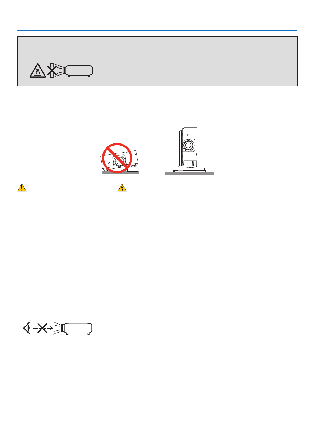
Donotusetheprojectorwithitleaningtotheleftandright.Thismayresultinamalfunction,however,portraitinstal-
lation*ispossible.Forportraitinstallation,installtheprojectorwiththeintakeventatthebottom.Observeprecautions
forportraitinstallation.
* Acustomizedstandandasafetycover(soldseparately)needtobeattachedtotheprojector.(→page136)
Fire and Shock Precautions
• Ensurethatthereissufcientventilationandthatventsareunobstructedtopreventthebuild-upofheatinsideyour
projector.Allowenoughspacebetweenyourprojectorandawall.(→pagevii)
• Donottrytotouchtheexhaustventontheleftfront(whenseenfromthefront)asitcanbecomeheatedwhilethe
projectoristurnedonandimmediatelyaftertheprojectoristurnedoff.Partsoftheprojectormaybecometemporarily
heatediftheprojectoristurnedoffwiththePOWERbuttonoriftheACpowersupplyisdisconnectedduringnormal
projectoroperation.
Usecautionwhenpickinguptheprojector.
• Preventforeignobjectssuchaspaperclipsandbitsofpaperfromfallingintoyourprojector.Donotattempttoretrieve
anyobjectsthatmightfallintoyourprojector.Donotinsertanymetalobjectssuchasawireorscrewdriverintoyour
projector.Ifsomethingshouldfallintoyourprojector,disconnectitimmediatelyandhavetheobjectremovedbya
qualiedservicepersonnel.
• Donotplaceanyobjectsontopoftheprojector.
• Donottouchthepowerplugduringathunderstorm.Doingsocancauseelectricalshockorre.
• Theprojectorisdesignedtooperateonapowersupplyof100-240VAC50/60Hz.Ensurethatyourpowersupply
tsthisrequirementbeforeattemptingtouseyourprojector.
• Donotlookintothelenswhiletheprojectorison.Seriousdamagetoyoureyescouldresult.
• Donotlookintothelightsourceusingopticalinstruments(suchasmagnifyingglassesandmirrors).Visualimpair-
mentcouldresult.
• Whenturningontheprojector,makesurenoonewithinprojectionrangeislookingatthelens.
• Keepanyitems(magnifyingglassetc.)outofthelightpathoftheprojector.Thelightpathbeingprojectedfromthe
lensisextensive,thereforeanykindofabnormalobjectsthatcanredirectlightcomingoutofthelens,cancause
anunpredictableoutcomesuchasareorinjurytotheeyes.
• Donotplaceanyobjects,whichareeasilyaffectedbyheat,infrontofaprojectorexhaustvent.
Doingsocouldleadtotheobjectmeltingorgettingyourhandsburnedfromtheheatthatisemittedfromtheexhaust
vent.

iv
Important Information
• Handlethepowercordcarefully.Adamagedorfrayedpowercordcancauseelectricshockorre.
- Donotuseanypowercordotherthantheonesuppliedwiththeprojector.
- Donotbendortugthepowercordexcessively.
- Donotplacethepowercordundertheprojector,oranyheavyobject.
- Donotcoverthepowercordwithothersoftmaterialssuchasrugs.
- Donotheatthepowercord.
- Donothandlethepowerplugwithwethands.
• Turnofftheprojector,unplugthepowercordandhavetheprojectorservicedbyaqualiedservicepersonnelunder
thefollowingconditions:
- Whenthepowercordorplugisdamagedorfrayed.
- Ifliquidhasbeenspilledintotheprojector,orifithasbeenexposedtorainorwater.
- Iftheprojectordoesnotoperatenormallywhenyoufollowtheinstructionsdescribedinthisuser’smanual.
- Iftheprojectorhasbeendroppedorthecabinethasbeendamaged.
- Iftheprojectorexhibitsadistinctchangeinperformance,indicatinganeedforservice.
• Disconnectthepowercordandanyothercablesbeforecarryingtheprojector.
• Turnofftheprojectorandunplugthepowercordbeforecleaningthecabinet.
• Turnofftheprojectorandunplugthepowercordiftheprojectorisnottobeusedforanextendedperiodoftime.
• WhenusingaLANcable:
Forsafety,donotconnecttotheterminalforperipheraldevicewiringthatmighthaveexcessivevoltage.
CAUTION
• Donotplaceyourngersinsidethelenshoodwhileperformingalensshift.Failuretodosocouldresultinngers
beingpinchedbetweenthecabinetandlens.
• Donotusethetilt-footforpurposesotherthanoriginallyintended.Misusessuchasgrippingthetilt-footorhang-
ingonthewallcancausedamagetotheprojector.
• Donotsendtheprojectorinthesoftcasebyparceldeliveryserviceorcargoshipment.Theprojectorinsidethe
softcasecouldbedamaged.
• Select[HIGH]inFanmodeifyoucontinuetousetheprojectorforconsecutivedays.(Fromthemenu,select
[SETUP]→[OPTIONS(1)]→[FANMODE]→[MODE]→[HIGH].)
• Donotbringtheprojectorholdingitbythelenshood.Theprojectormaybedroppeddownanditmaybecause
ofhumaninjury.
• Ifasafetycover(soldseparately)isused,donotcarrytheprojectorbythecover.Thesafetycovercancomeoff
andtheprojectormaybedropped,causingpersonalinjury.
• Donotunplugthepowercordfromthewalloutletorprojectorwhentheprojectorispoweredon.Doingsocan
causedamagetotheACINterminaloftheprojectorand(or)theprongplugofthepowercord.
ToturnofftheACpowersupplywhentheprojectorispoweredon,usetheprojector’smainpowerswitch,apower
stripequippedwithaswitch,orabreaker.
Caution on Handling the Optional Lens
Whenshippingtheprojectorwiththelens,removethelensbeforeshippingtheprojector.Alwaysattachthedustcap
tothelenswheneveritisnotmountedontheprojector.Thelensandthelensshiftmechanismmayencounterdamage
causedbyimproperhandlingduringtransportation.
Donotholdthelenspartwhencarryingtheprojector.
Doingsocouldcausethefocusringtorotate,resultinginaccidentaldroppingoftheprojector.
Remote Control Precautions
• Handletheremotecontrolcarefully.
• Iftheremotecontrolgetswet,wipeitdryimmediately.
• Avoidexcessiveheatandhumidity.
• Donotshort,heat,ortakeapartbatteries.
• Donotthrowbatteriesintore.
• Ifyouwillnotbeusingtheremotecontrolforalongtime,removethebatteries.
• Ensurethatyouhavethebatteries’polarity(+/−)alignedcorrectly.
• Donotusenewandoldbatteriestogether,orusedifferenttypesofbatteriestogether.
• Disposeofusedbatteriesaccordingtoyourlocalregulations.
v
Important Information
Light Module
1. Alightmodulecontainingmultiplelaserdiodesisequippedintheproductasthelightsource.
2. Theselaserdiodesaresealedinthelightmodule.Nomaintenanceorserviceisrequiredfortheperformanceof
thelightmodule.
3. Enduserisnotallowedtoreplacethelightmodule.
4. Contactqualieddistributorforlightmodulereplacementandfurtherinformation.
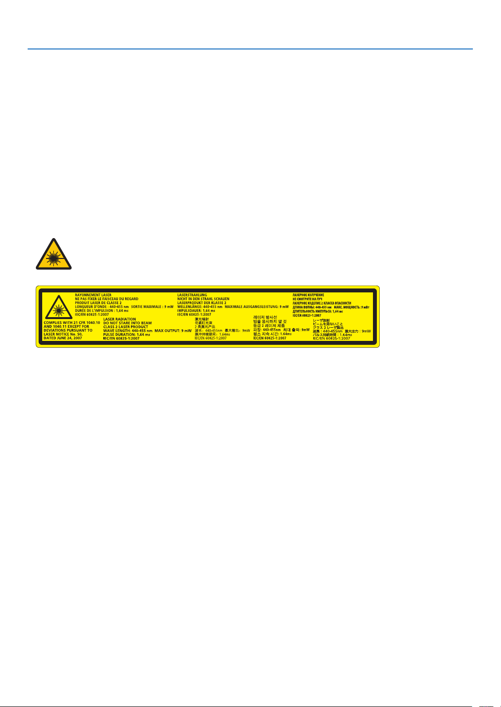
Laser Safety Caution
• ThisproductisclassiedasClass2ofIEC60825-1Secondedition2007-03.
AlsocomplieswithFDAperformancestandards21CFR1040.10and1040.11forlaserproductsexceptfordevia-
tionspursuanttoLaserNoticeNo.50,datedJune24,2007.
Obeythelawsandregulationsofyourcountryinrelationtotheinstallationandmanagementofthedevice.
• Thelasermoduleisequippedinthisproduct.
Useofcontrolsoradjustmentsofproceduresotherthanthosespeciedhereinmayresultinhazardousradiation
exposure.
DONOTSTAREINTOTHELENSWHILEINUSE.
• Thiscautionlabelsareonthesidefaceofthecabinet.
TheexplanatorylabeloftheCLASS2LASERPRODUCTSisontherightsideoftheprojectorbody.
About High Altitude mode
• Set[FANMODE]to[HIGH]whenusingtheprojectorataltitudesapproximately2500feet/760metersorhigher.
Usingtheprojectorataltitudesapproximately2500feet/760metersorhigherwithoutsettingto[HIGH]cancause
theprojectortooverheatandtheprotectorcouldshutdown.Ifthishappens,waitacoupleminutesandturnonthe
projector.
• Usingtheprojectorataltitudesapproximately2500feet/760metersorhighercanshortenthelifeofopticalcompo-
nentssuchasthelightmodule.
About Copyright of original projected pictures:
Pleasenotethatusingthisprojectorforthepurposeofcommercialgainortheattractionofpublicattentioninavenue
suchasacoffeeshoporhotelandemployingcompressionorexpansionofthescreenimagewiththefollowingfunc-
tionsmayraiseconcernabouttheinfringementofcopyrightswhichareprotectedbycopyrightlaw.
[ASPECTRATIO],[KEYSTONE],Magnifyingfeatureandothersimilarfeatures.
Turkish RoHS information relevant for Turkish market
EEE Yönetmeliğine Uygundur.
Thisdeviceisnotintendedforuseinthedirecteldofviewatvisualdisplayworkplaces.Toavoidincommodingreec-
tionsatvisualdisplayworkplacesthisdevicemustnotbeplacedinthedirecteldofview.

vi
Important Information
Health precautions to users viewing 3D images
Beforeviewing,besuretoreadhealthcareprecautionsthatmaybefoundintheuser’smanualincludedwithyour3D
eyeglassesoryour3DcompatiblecontentsuchasBlu-rayDiscs,videogames,computer’svideolesandthelike.
Toavoidanyadversesymptoms,heedthefollowing:
• Donotuse3Deyeglassesforviewinganymaterialotherthan3Dimages.
• Allowadistanceof2m/7feetorgreaterbetweenthescreenandauser.Viewing3Dimagesfromtooclosea
distancecanstrainyoureyes.
• Avoidviewing3Dimagesforaprolongedperiodoftime.Takeabreakof15minutesorlongeraftereveryhour
ofviewing.
• Ifyouoranymemberofyourfamilyhasahistoryoflight-sensitiveseizures,consultadoctorbeforeviewing3D
images.
• Whileviewing3Dimages,ifyougetsicksuchasnausea,dizziness,queasiness,headache,eyestrain,blurry
vision,convulsions,andnumbness,stopviewingthem.Ifsymptomsstillpersist,consultadoctor.
• View3Dimagesfromthefrontofthescreen.Viewingfromananglemaycausefatigueoreyestrain.
Power management function
Inordertokeeppowerconsumptionlow,thefollowingpowermanagementfunctions(1)and(2)havebeensetwhen
shippedfromthefactory.Pleasedisplaytheon-screenmenuandchangethesettings(1)and(2)accordingtothe
aimofusingtheprojector.
1. STANDBY MODE (Factory preset: NORMAL)
• When[NORMAL]isselectedfor[STANDBYMODE],thefollowingterminalsandfunctionswillnotwork:
HDMIOUTterminal,Ethernet/HDBaseTPort,USBPort,LANfunctions,MailAlertfunction
(→page114)
2. AUTO POWER OFF (Factory preset: 1 hour)
• When[1:00]isselectedfor[AUTOPOWEROFF],youcanenabletheprojectortoautomaticallyturnoffin1
hourifthereisnosignalreceivedbyanyinputorifnooperationisperformed.
(→page115)
vii
Important Information
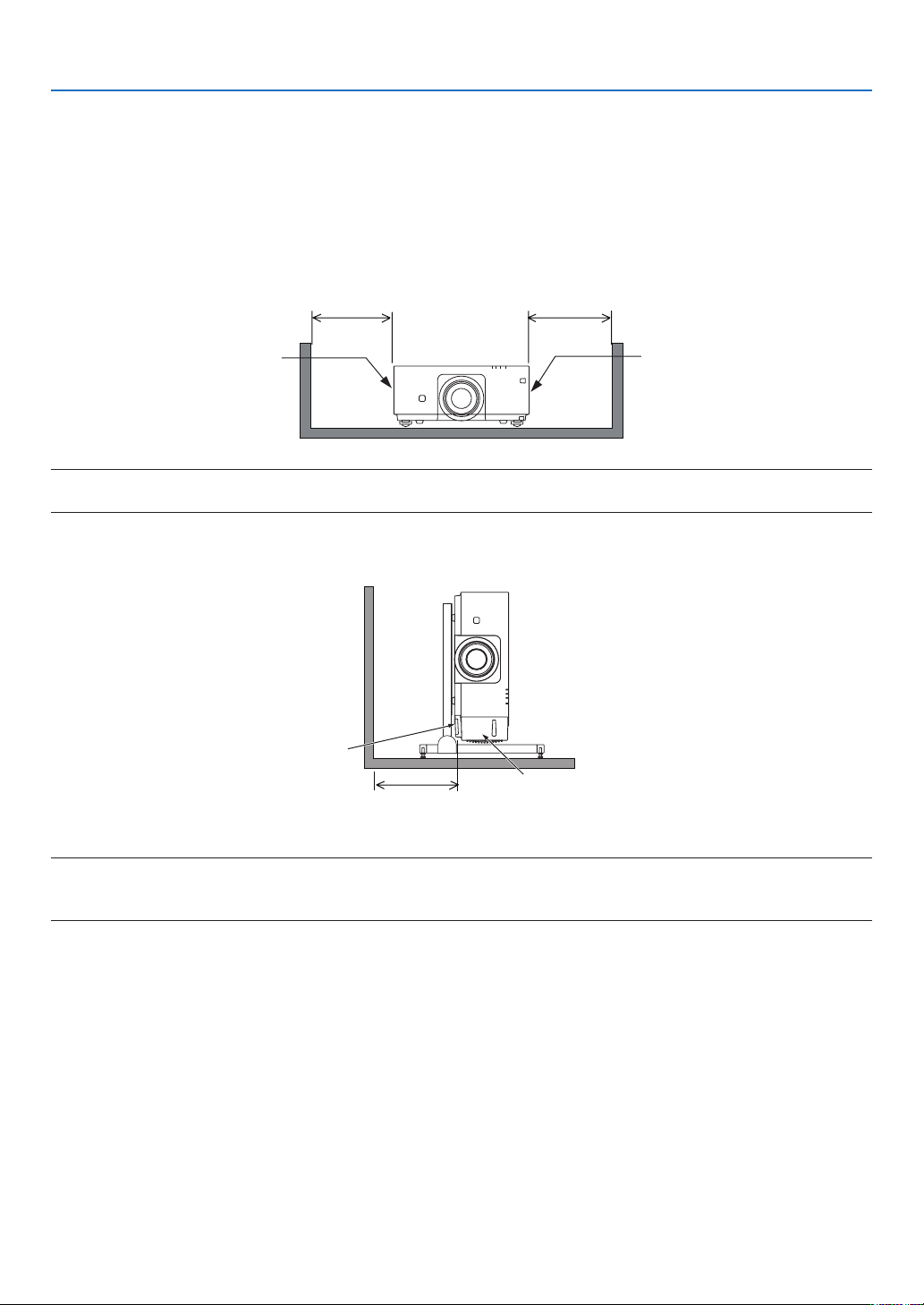
Clearance for Installing the Projector
Allowampleclearancebetweentheprojectoranditssurroundingsasshownbelow.
Thehightemperatureexhaustcomingoutofthedevicemaybesuckedintothedeviceagain.
AvoidinstallingtheprojectorinaplacewhereairmovementfromtheHVACisdirectedattheprojector.
HeatedairfromtheHVACcanbetakeninbytheprojector'sintakevent.Ifthishappens,thetemperatureinsidethe
projectorwillrisetoohighcausingtheover-temperatureprotectortoautomaticallyturnofftheprojectorspower.
Example 1 – If there are walls on both sides of the projector.
30cm/11.8"orgreater 30cm/11.8"orgreater
IntakeventExhaustvent
NOTE:
The drawing shows the proper clearance required for the front, back and top of the projector.
Example 2 – In the case of portrait projection.
Intakevent
Safetycover
30cm/11.8"orgreater
NOTE:
• Thedrawingshowstheproperclearancerequiredforthefront,backandtopoftheprojector.
• Seepage135 for an installation example on portrait projection.

viii
Table of Contents
Important Information ............................................................................................ i
1. Introduction ...........................................................................................................1
❶What’sintheBox? ..........................................................................................................1
❷IntroductiontotheProjector ...........................................................................................2
CongratulationsonYourPurchaseoftheProjector ..................................................2
General .....................................................................................................................2
Lightsource·Brightness ..........................................................................................2
Installation ................................................................................................................. 2
Videos .......................................................................................................................3
Network ..................................................................................................................... 3
Energy-saving ...........................................................................................................3
Aboutthisuser’smanual ........................................................................................... 4
❸PartNamesoftheProjector ...........................................................................................5
Front/Top ...................................................................................................................5
Rear ..........................................................................................................................6
Controls/IndicatorPanel ............................................................................................ 7
TerminalsFeatures ...................................................................................................8
❹PartNamesoftheRemoteControl ................................................................................9
BatteryInstallation ..................................................................................................10
RemoteControlPrecautions ................................................................................... 10
OperatingRangeforWirelessRemoteControl ....................................................... 11
UsingtheRemoteControlinWiredOperation ........................................................ 11
2. Projecting an Image (Basic Operation) ...............................................12
❶FlowofProjectinganImage .........................................................................................12
❷ConnectingYourComputer/ConnectingthePowerCord ..............................................13
❸TurningontheProjector ...............................................................................................14
NoteonStartupscreen(MenuLanguageSelectscreen) .......................................15
❹SelectingaSource .......................................................................................................16
Selectingthecomputerorvideosource..................................................................16
❺AdjustingthePictureSizeandPosition ........................................................................18
Adjustingtheverticalpositionofaprojectedimage(Lensshift) .............................19
Focus ......................................................................................................................21
Zoom ....................................................................................................................... 21
AdjustingtheTiltFoot .............................................................................................22
❻OptimizingComputerSignalAutomatically ..................................................................23
AdjustingtheImageUsingAutoAdjust ...................................................................23
❼TurningofftheProjector ...............................................................................................24
❽AfterUse.......................................................................................................................25
3. Convenient Features ......................................................................................26
❶Turnoffthelightoftheprojector(LENSSHUTTER) ....................................................26
❷TurningofftheImage ....................................................................................................26
❸TurningOfftheOn-ScreenMenu(On-ScreenMute) ....................................................26
❹FreezingaPicture ........................................................................................................27
❺MagnifyingaPicture .....................................................................................................28

ix
Table of Contents
❻ChangingLIGHTMODE/CheckingEnergy-SavingEffectUsingLIGHTMODE
[LIGHTMODE]........................................................................................................29
CheckingEnergy-SavingEffect[CARBONMETER] ..............................................31
❼CorrectingHorizontalandVerticalKeystoneDistortion[CORNERSTONE] .................32
❽PreventingtheUnauthorizedUseoftheProjector[SECURITY] ..................................35
❾Projecting3Dvideos.....................................................................................................38
Proceduretowatch3Dvideosusingthisprojector .................................................38
Whenvideoscannotbeviewedin3D .....................................................................41
❿ControllingtheProjectorbyUsinganHTTPBrowser ..................................................42
4. Multi-Screen Projection ...............................................................................48
❶Thingsthatcanbedoneusingmulti-screenprojection ................................................48
Case1.Usingasingleprojectortoprojecttwotypesofvideos[PIP/PICTURE
BYPICTURE] .........................................................................................................48
Case2.Usingfourprojectors(resolution:WUXGA)toprojectvideoswitha
resolutionof2560×1600pixels[TILING]...............................................................49
Thingstonotewheninstallingprojectors ................................................................ 51
❷DisplayingTwoPicturesattheSameTime ...................................................................52
Projectingtwoscreens ............................................................................................ 53
Switchingthemaindisplaywiththesub-displayandviceversa .............................54
Restrictions .............................................................................................................55
❸DisplayingaPictureUsing[EDGEBLENDING] ...........................................................56
Settingtheoverlapofprojectionscreens ................................................................ 57
BlackLevelAdjustment ...........................................................................................60
5. Using On-Screen Menu .................................................................................62
❶UsingtheMenus ...........................................................................................................62
❷MenuElements .............................................................................................................63
❸ListofMenuItems ........................................................................................................64
❹MenuDescriptions&Functions[INPUT] ......................................................................70
HDMI ....................................................................................................................... 70
DisplayPort ..............................................................................................................70
BNC ........................................................................................................................70
BNC(CV) .................................................................................................................70
BNC(Y/C) ................................................................................................................70
COMPUTER ...........................................................................................................70
HDBaseT ................................................................................................................70
SLOT ....................................................................................................................... 70
ENTRYLIST ...........................................................................................................70
TESTPATTERN ...................................................................................................... 70
❺MenuDescriptions&Functions[ADJUST] ................................................................... 74
[PICTURE] ..............................................................................................................74
[IMAGEOPTIONS] .................................................................................................78
[VIDEO] ................................................................................................................... 82
[3DSETTINGS] ......................................................................................................84
❻MenuDescriptions&Functions[DISPLAY] ..................................................................85
[PIP/PICTUREBYPICTURE] ................................................................................. 85
[GEOMETRICCORRECTION] ...............................................................................87
[EDGEBLENDING] ................................................................................................91

x
Table of Contents
[MULTISCREEN]....................................................................................................92
❼MenuDescriptions&Functions[SETUP] ..................................................................... 94
[MENU] ...................................................................................................................94
[INSTALLATION] .....................................................................................................96
[CONTROL] ............................................................................................................99
[NETWORKSETTINGS] ....................................................................................... 107
[SOURCEOPTIONS] ...........................................................................................112
[POWEROPTIONS] .............................................................................................114
ReturningtoFactoryDefault[RESET] ..................................................................116
❽MenuDescriptions&Functions[INFO.] .....................................................................117
[USAGETIME] ......................................................................................................117
[SOURCE(1)] ........................................................................................................117
[SOURCE(2)] ........................................................................................................118
[SOURCE(3)] ........................................................................................................118
[SOURCE(4)] ........................................................................................................118
[WIREDLAN] ........................................................................................................119
[VERSION(1)] .......................................................................................................119
[OTHERS] .............................................................................................................119
[HDBaseT] ............................................................................................................120
6. Connecting to Other Equipment ...........................................................121
❶Mountingalens(soldseparately) ...............................................................................121
PartNamesoftheLensMount .............................................................................121
Mountingthelens..................................................................................................122
Removingthelens ................................................................................................124
❷MakingConnections ...................................................................................................125
AnalogRGBsignalconnection .............................................................................125
DigitalRGBsignalconnection ..............................................................................126
ConnectinganExternalMonitor ...........................................................................129
ConnectingYourBlu-rayPlayerorOtherAVEquipment ....................................... 130
ConnectingComponentInput ...............................................................................131
ConnectingHDMIInput.........................................................................................132
ConnectingtoaWiredLAN ..................................................................................133
ConnectingtoaHDBaseTtransmissiondevice(soldcommercially) .................... 134
Portraitprojection(verticalorientation) .................................................................135
Stackingprojectors ...............................................................................................138
7. Maintenance .....................................................................................................141
❶CleaningtheLens.......................................................................................................141
❷CleaningtheCabinet ..................................................................................................141
8. User Supportware ..........................................................................................142
❶OperatingEnvironmentforSoftwareIncludedonCD-ROM .......................................142
NamesandFeaturesofBundledSoftwarePrograms ...........................................142
Downloadservice .................................................................................................142
OperatingEnvironment .........................................................................................142
❷InstallingSoftwareProgram .......................................................................................143
InstallationforWindowssoftware .......................................................................... 143
❸OperatingtheProjectorViatheLAN(VirtualRemoteTool) ........................................146
ConnecttheprojectortoaLAN. ............................................................................ 147

xi
Table of Contents
❹ControllingtheProjectoroveraLAN(PCControlUtilityPro4/Pro5) ........................149
9. Appendix ..............................................................................................................153
❶Throwdistanceandscreensize .................................................................................153
Lenstypesandthrowdistance .............................................................................153
Tablesofscreensizesanddimensions ................................................................155
Lensshiftingrange ................................................................................................156
❷MountingtheOptionalBoard(soldseparately) ..........................................................157
❸CompatibleInputSignalList .......................................................................................159
❹Specications .............................................................................................................162
❺CabinetDimensions ...................................................................................................165
❻Pinassignmentsandsignalnamesofmainterminals ...............................................166
❼Troubleshooting ..........................................................................................................168
IndicatorMessages ............................................................................................... 168
CommonProblems&Solutions ............................................................................170
Ifthereisnopicture,orthepictureisnotdisplayedcorrectly. ............................... 172
❽PCControlCodesandCableConnection ..................................................................173
❾TroubleshootingCheckList ......................................................................................... 174
1
1. Introduction
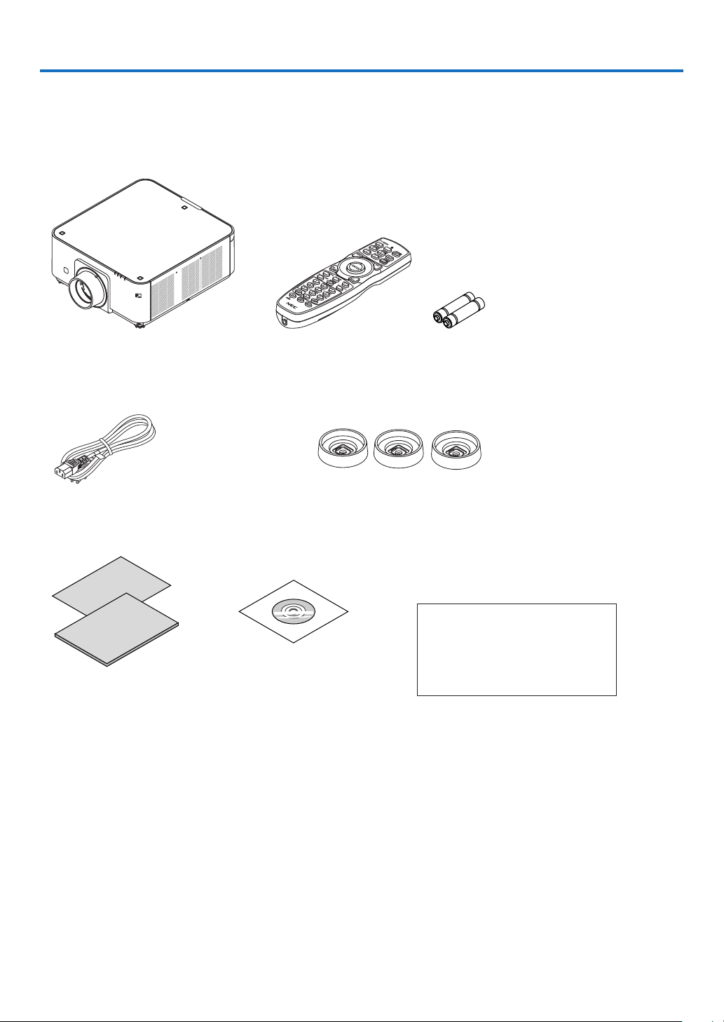
❶ What’s in the Box?
Makesureyourboxcontainseverythinglisted.Ifanypiecesaremissing,contactyourdealer.
Pleasesavetheoriginalboxandpackingmaterialsifyoueverneedtoshipyourprojector.
Projector
Dustcapforlens
* Theprojectorisshippedwithout
alens.Forthetypesoflensand
throwdistances,seepage153.
Remotecontrol
(7N901041)
AAalkalinebatteries(x2)
Powercord
(US:79TG0251)
(EU:79TG0261)
3Stackingholders(79TG0291)
Whenstackingprojectors(doublestacking),thetiltfootoftheupper
projectorwillbeplacedontothesestackingholders.(→page139)
For North America only
Limitedwarranty
For customers in Europe:
YouwillndourcurrentvalidGuar-
anteePolicyonourWebSite:
www.nec-display-solutions.com
• ImportantInfomation
(7N8N5111)
• QuickSetupGuide(7N8N5131)
• SecuritySticker
(Usethisstickerwhensecurity
passwordisseton.)
NECProjectorCD-ROM
User’smanual(PDF)andthe
utilitysoftware
(7N952062)

2
1. Introduction
❷ Introduction to the Projector
Thissectionintroducesyoutoyournewprojectoranddescribesthefeaturesandcontrols.
Congratulations on Your Purchase of the Projector
Thisprojectorisoneoftheverybestprojectorsavailabletoday.Theprojectorenablesyoutoprojectpreciseimages
upto500inchesacross(measureddiagonally)fromyourPCorMaccomputer(desktopornotebook),VCR,Blu-ray
player,ordocumentcamera.
Youcanusetheprojectoronatabletoporcart,youcanusetheprojectortoprojectimagesfrombehindthescreen,
andtheprojectorcanbepermanentlymountedonaceiling*
1
.Theremotecontrolcanbeusedwirelessly.
*
1
Donotattempttomounttheprojectoronaceilingyourself.
Theprojectormustbeinstalledbyqualiedtechniciansinordertoensureproperoperationandreducetherisk
ofbodilyinjury.
Inaddition,theceilingmustbestrongenoughtosupporttheprojectorandtheinstallationmustbeinaccordance
withanylocalbuildingcodes.Pleaseconsultyourdealerformoreinformation.
General
• Single-chipDLPprojectorwithhighresolutionandhighbrightness
Modelname DMDpanel Resolution Aspectratio
PX602UL-WH/PX602UL-BK 0.67type 1,920×1,200pixels 16:10
PX602WL-WH/PX602WL-BK
0.65type 1,280×800pixels 16:10
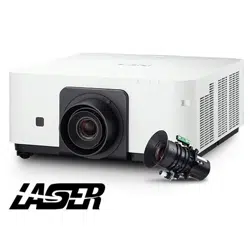
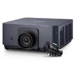
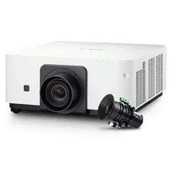
Light source · Brightness
• Along-lifelaserdiodeisequippedinthelightmodule
Theproductcanbeoperatedatlowcostbecausethelaserlightsourcecanbeusedforalongtimewithoutrequir-
ingreplacementormaintenance.
• Brightnesscanbeadjustedwithinawiderange
Unlikewithordinarylightsources,thebrightnesscanbeadjustedfrom20to100%in1%increments.
• [CONSTANTBRIGHTNESS]mode
Brightnessnormallydecreaseswithuse,butbyselecting[CONSTANTBRIGHTNESS]mode,sensorsinsidethe
projectordetectandautomaticallyadjusttheoutput,therebymaintainingconstantbrightnessthroughoutthelife
ofthelightmodule.
However,ifbrightnessoutputissetatthemaximum,brightnesswilldecreasewithuse.
Installation
• Widerangeofoptionallensesselectableaccordingtotheplaceofinstallation
Thisprojectorsupports4types,howeverPX602UL-WHandPX602UL-BKsupport3typesofoptionallenses,
providingaselectionoflensesadaptedtoavarietyofplacesofinstallationandprojectionmethods.
Inaddition,thelensescanbemountedandremovedinonetouch.
Notethatnolensismounteduponshipmentfromthefactory.Pleasepurchaseoptionallensesseparately.
• Tilt-free,portraitprojection
Thisprojectorcanbesettoanyanglewithinavertical360°range.
Itcanalsorotatethepicture90°intoportraitorientation.
Thisprojectorcannotbeinstalledwithrightorleftslantbesidestheportraitprojection.
• Doublestackableforhighlightoutputprojection
Bystacking2projectors,increasedbrightnessonalargescreenispossible.
• Powerlenscontrolforquickandeasyadjustment
Byusingbuttonsontheprojectorortheremotecontrol,zoom,focus,andposition(lensshift)canbeadjusted.

3
1. Introduction
Videos
• Widerangeofinput/outputterminals(HDMI,DisplayPort,BNC,HDBaseT,etc.)andbuilt-inmonauralspeaker
Theprojectorisequippedwithavarietyofinput/outputterminals:HDMI,DisplayPort,BNC(5-core),computer
(analog),HDBaseT,etc.
Theprojector’sHDMIinput/outputterminalsandDisplayPortinputterminalsupportHDCP.
HDBaseT,promotedandadvancedbytheHDBaseTAlliance,isaconsumerelectronic(CE)andcommercialcon-
nectivitytechnology.
• Slotforoptionalboard
Thisprojectorhasaslotforoptionalboards(soldseparately).
• Simultaneousdisplayof2images(PIP/PICTUREBYPICTURE)
Twoimagescanbeprojectedsimultaneouslywithasingleprojector.
Therearetwotypesoflayoutsforthetwoimages:“picture-in-picture”(PIP)inwhichasub-pictureisdisplayed
onthemainpicture,and“picture-by-picture”(PICTUREBYPICTURE)inwhichthemainandsubpicturesare
displayednexttoeachother.
• Multi-screenprojectionusingmultipleprojectors
ThisprojectorisequippedwithmultipleHDMIinput&outputterminalsthatcanconnectmultipleprojectorsina
daisychain.Ahighqualitypictureisachievedbydividingandprojectinghighresolutionvideosamongthevarious
projectors.
Furthermore,theboundariesofthescreensaresmoothedusinganedgeblendingfunction.
• SupportsHDMI3Dformat
Thisprojectorcanbeusedtowatchvideosin3Dusingcommercially-availableactiveshutter-type3Deyewear
and3DemittersthatsupportXpand3D.
Network
• Convenientutilitysoftware(UserSupportware)providedasstandard
ThethreeutilitysoftwarestoredintheenclosedNECProjectorCD-ROM(VirtualRemoteTool,PCControlUtility
Pro4(forWindows)andPCControlUtilityPro5(forMacOS))canbeused.
• CRESTRONROOMVIEWcompatible
ThisprojectorsupportsCRESTRONROOMVIEW,allowingmultipledevicesconnectedtothenetworktobeman-
agedfromacomputerorcontroller.
Energy-saving
• Energy-savingdesignwithastandbypowerconsumptionof0.5watts
Whentheon-screenmenu’sstandbymodeissetto“NORMAL”,thepowerconsumptioninthestandbymodeis
0.5watts.
• “LIGHTMODE”forlowpowerconsumptionand“CarbonMeter”display
Theprojectorisequippedwithan“LIGHTMODE”forreducingpowerconsumptionduringuse.Furthermore,the
power-savingeffectwhentheLIGHTMODEissetisconvertedintotheamountofreductionsofCO
2
emissions
andthisisindicatedontheconrmationmessagedisplayedwhenthepoweristurnedoffandat“Information”on
theon-screenmenu(CARBONMETER).

4
1. Introduction
About this user’s manual
Thefastestwaytogetstartedistotakeyourtimeanddoeverythingrightthersttime.Takeafewminutesnowto
reviewtheuser’smanual.Thismaysaveyoutimelateron.Atthebeginningofeachsectionofthemanualyou’llnd
anoverview.Ifthesectiondoesn’tapply,youcanskipit.
5
1. Introduction
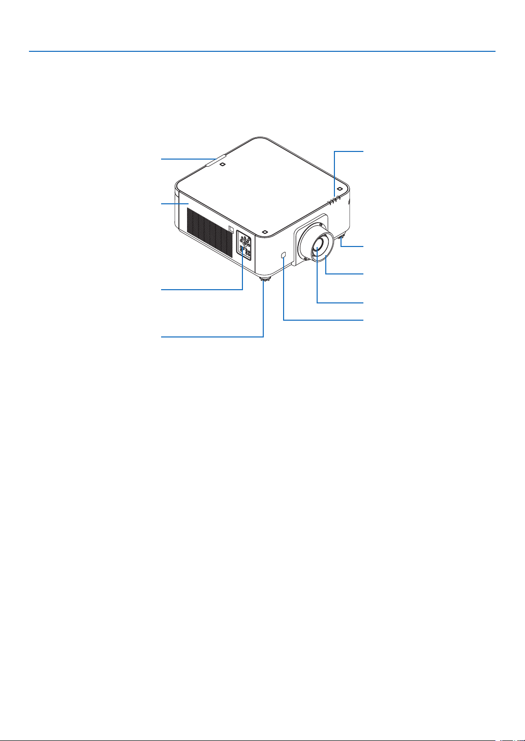
❸ Part Names of the Projector
Front/Top
Thelensissoldseparately.ThedescriptionbelowisforwhentheNP35ZLlensismounted.
Controls
(→page7)
Lens
RemoteSensor
(→page11)
LensHood
Protectsthelens.
RemoteSensor(locatedonthe
frontandtherear)
(→page11)
AdjustableTiltFoot
(→page22)
IndicatorPanel
(→page7)
AdjustableTiltFoot
(→page22)
Exhaustvent
Heatedairisexhaustedfromhere.
6
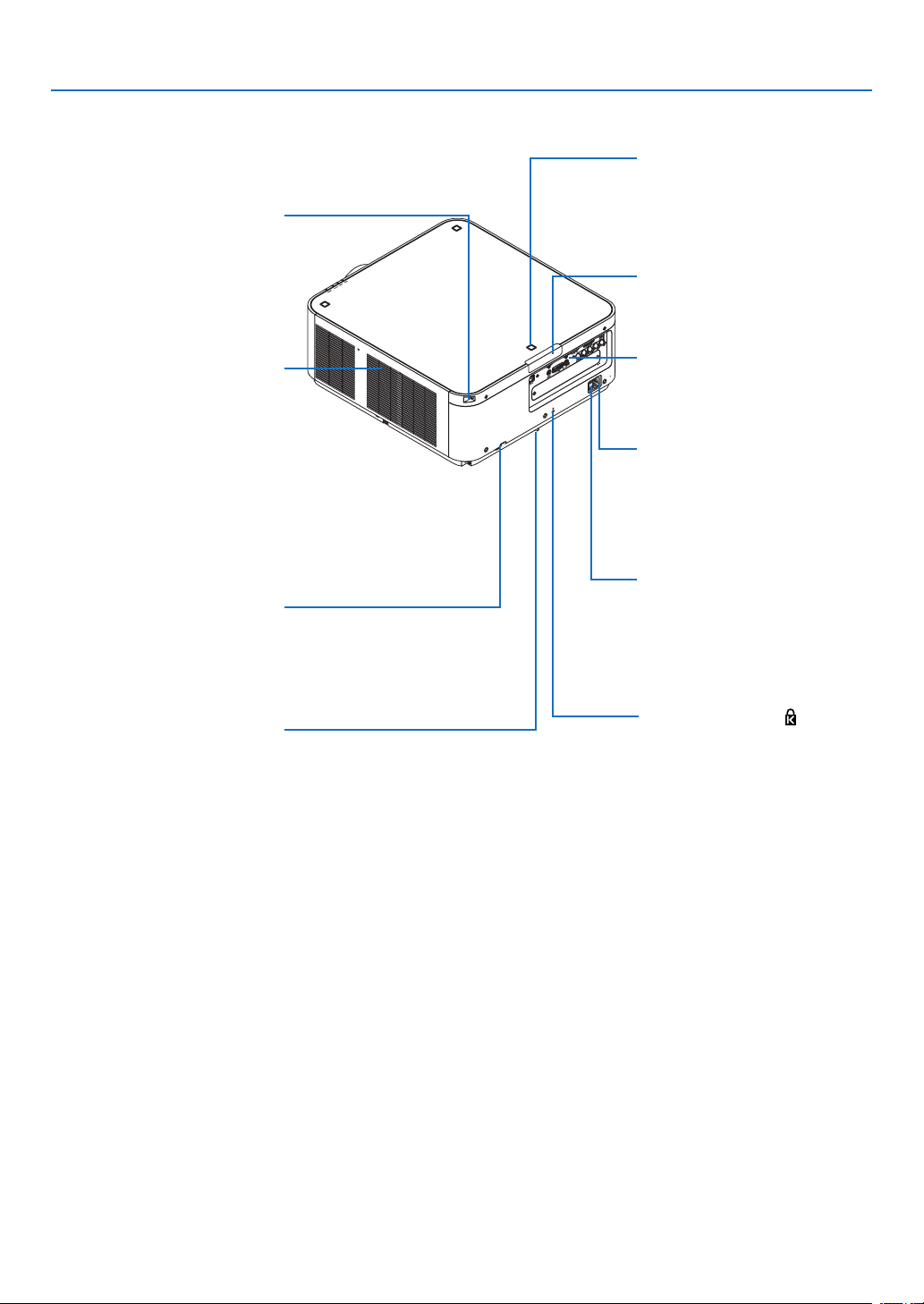
1. Introduction
Rear
Stackingholderxingposition
(3positions)
Forstackinguptheprojectors,fas-
tenupthestackingholderssupplied
withthisprojector.
Safetycoverxinghole
(7positions)
Thexingholesforinstallingthe
safetycover(soldseparately)thatis
usedforportraitinstallation.
RemoteSensor(locatedonthe
frontandtherear)
(→page11)
ACINterminal
Connectthesuppliedpowercord’s
three-pinplughere,andplugthe
otherendintoanactivewalloutlet.
(→page13)
Mainpowerswitch
WhileACpowerisbeingsupplied,
setthemainpowerswitchtoON
position(|),thenyourprojectorwill
enterastandbystate.
* ThissecurityslotsupportstheMicroSaver
®
SecuritySystem.
Built-inSecuritySlot( )*
SecurityBar
Attachananti-theftdevice.
Thesecuritybaracceptssecurity
wiresorchainsupto0.18inch/4.6
mmindiameter.
AdjustableTiltFoot
(→page22)
Intakevent
Takesinoutsideairtocooltheunit.
Thereareairintakeandventilation
holesonthebottom.
(→pagevii,141)
Terminals
(→
page8)
7
1. Introduction
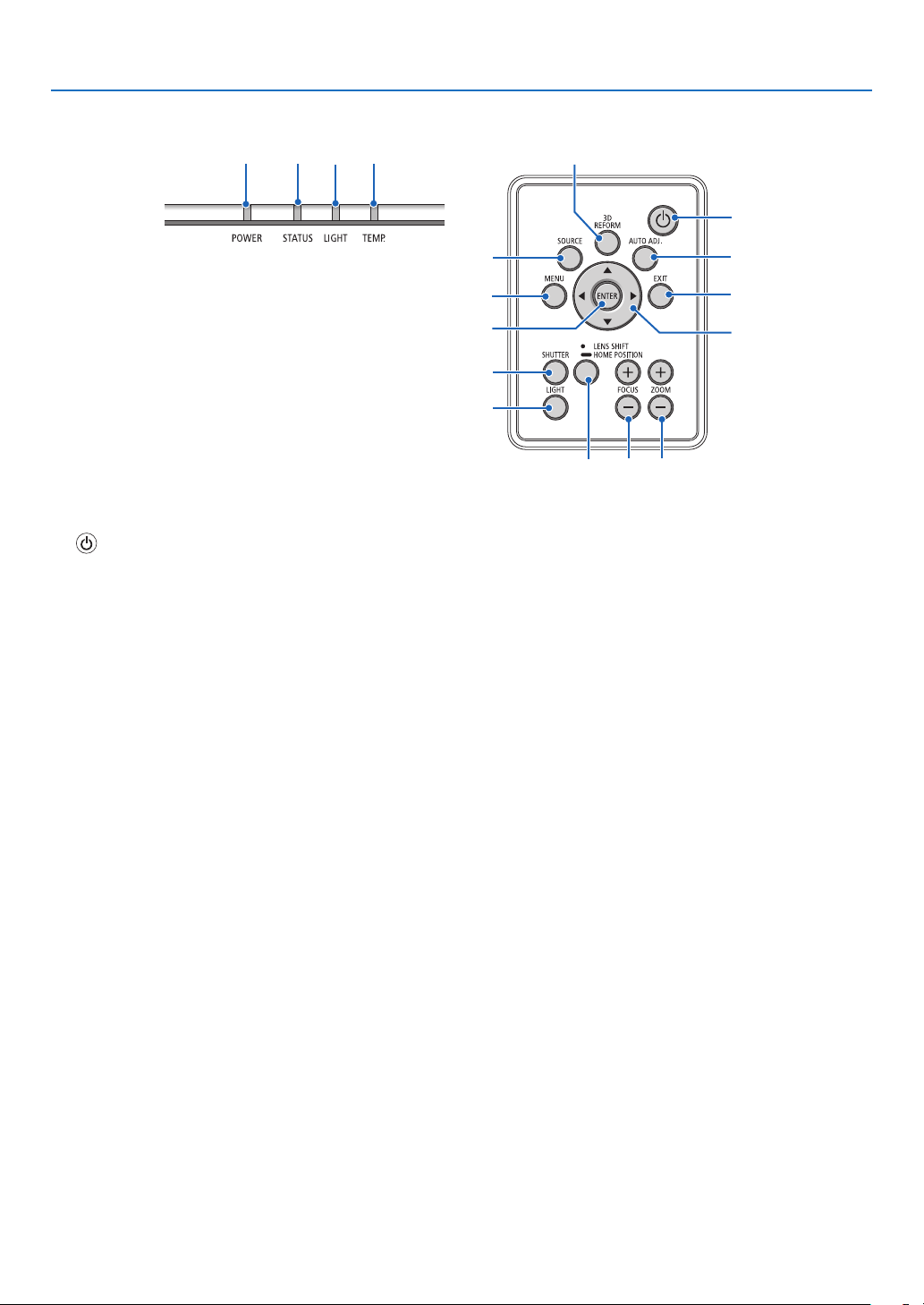
Controls/Indicator Panel
11
10
7
2
3
4
5
8
1
6
13
14
15 16 17
12
9
1. (POWER)Button
(→page14,24)
2. POWERIndicator
(→page14,15,24,168)
3. STATUS Indicator
(→page168)
4. LIGHT Indicator
(→page29,169)
5. TEMP.Indicator
(→page169)
6. SOURCEButton
(→page16)
7. AUTOADJ.Button
(→page23)
8. 3DREFORMButton
(→page32)
9. MENUButton
(→page62)
10.▲▼◀▶
Buttons
(→page62)
11.ENTERButton
(→page62)
12.EXITButton
(→page62)
13.SHUTTERButton
(→page26)
14.LIGHTButton
(→page29)
15.LENSSHIFT/HOMEPOSITIONButton
(→page19,26,124,156)
16.FOCUS+/−Button
(→page21)
17.ZOOM+/−Button
(→page21)
8
1. Introduction
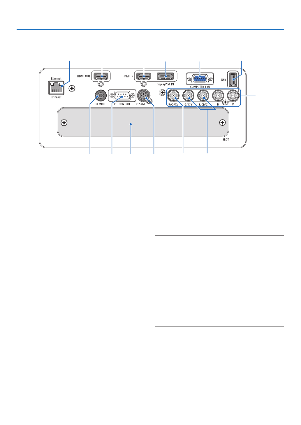
Terminals Features
9 7
1
4
238
1312
1011
56
1. COMPUTER1IN/ComponentInputTerminal
(MiniD-Sub15Pin)
(→page13,125,131,166)
2. DisplayPortINTerminal(DisplayPort20Pin)
(→page126,166)
3. HDMIINTerminal(TypeA)
(→page126,128,132,166)
4. BNCInput[R/Cr/CV,G/Y/Y,B/Cb/C,H,V]Termi-
nals(BNC×5)
(→page125,130)
5. BNC(Y/C)InputTerminal(BNC×2)
(→page130)
6. BNC(CV)InputTerminal(BNC×1)
(→page130)
7. USBPort(TypeA)
(→page167)
(Forfutureexpansion.Thisportallowsforpowersup-
ply.)
8. HDMIOUTTerminal(TypeA)
(→page129)
9. Ethernet/HDBaseTPort(RJ-45)
(→page133,134,167)
10.3DSYNCTerminal(MiniDIN4Pin)
(→page40)
11.PCCONTROLPort(D-Sub9Pin)
(→page167,173)
Use this port to connect a PC or control system.
Thisenablesyoutocontroltheprojectorusingserial
communicationprotocol.Ifyouarewritingyourown
program,typicalPCcontrolcodesareonpage173.
12.REMOTETerminal(StereoMini)
Usethisjackforwiredremotecontroloftheprojector
usingacommerciallyavailableremotecablewith⌀3.5
stereomini-plug(withoutresistance).
Connecttheprojectorandthesuppliedremotecontrol
usingacommerciallyavailablewiredremotecontrol
cable.
(→
page11)
NOTE:
• WhenaremotecontrolcableisconnectedtotheREMOTE
terminal, infrared remote control operations cannot be per-
formed.
• PowercannotbesuppliedfromtheREMOTEterminaltothe
remote control.
• When [HDBaseT] is selected in the [REMOTE SENSOR]
and the projector is connected to a commercially-available
transmissiondevicethatsupportsHDBaseT,remotecontrol
operations in infra-red cannot be carried out if transmission
of remote control signals has been set up in the transmission
device.However,remotecontrolusinginfraredrayscanbe
carried out when the power supply of the transmission device
is switched off.
13. SLOT
(→page157)
9
1. Introduction
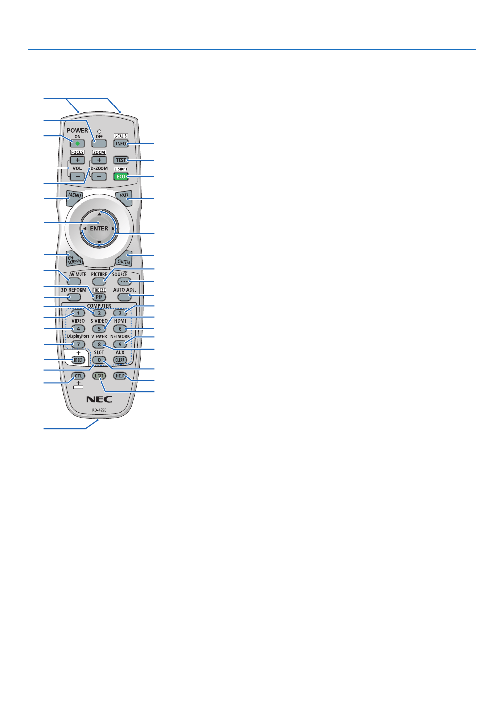
❹ Part Names of the Remote Control
1. Infrared Transmitter
(→page11)
2. RemoteJack
Connectacommerciallyavailable
remotecablehereforwiredopera-
tion.(→page11)
3. POWERONButton
(→page14)
4. POWEROFFButton
(→page24)
5. INFO/L-CALIB.Button
Displaythe[SOURCE(1)]screen
oftheon-screenmenu.
(→page117)
6. VOL./FOCUS+/−Buttons
(→page21)
7. D-ZOOM/ZOOM+/−Buttons
(→page28)
8. TESTButton
(→page70)
9. ECO/L-SHIFTButton
(→page20,29)
10.MENUButton
(→page62)
11.EXITButton
(→page62)
12.ENTERButton
(→page62)
13. ▲▼◀▶Button
(→page62)
14.ON-SCREENButton
(→page26)
15.SHUTTERButton
(→page26)
16.AV-MUTEButton
(→page26)
17.PICTUREButton
(→page74,76)
18.SOURCEButton
(→page16)
19.3DREFORMButton
(→page32)
20.PIP/FREEZEButton
(→page27,53)
1
3
4
6
14
10
12
16
20
7
2
5
8
9
11
15
18
17
13
21
19
25
28
32
23
22
35
24
30
26
29
34
27
31
36
33
21.AUTOADJ.Button
(→page23)
22,23,24.COMPUTER1/2/3But-
ton
(→
page16)
25.VIDEOButton
(→page16)
26.S-VIDEOButton
(→page16)
27.HDMIButton
(→page16)
28.DisplayPortButton
(→page16)
29.VIEWERButton
(TheVIEWERbuttonwillnotwork
onthisseriesofprojectors.)
30.NETWORKButton
(→page16)
31.SLOTButton
(→page158)
32.IDSETButton
(→page105)
33.Numeric(0to9/CLEAR)But-
tons
(→
page105)
(TheAUXbuttonwillnotworkon
thisseriesofprojectors.)
34.CTLButton
Thisbuttonisusedinconjunction
with other buttons, similar to a
CTRLkeyonacomputer.
35.LIGHTButton
Thisbuttonisusedtoturnonthe
backlight for the remote control
buttons.
Thebacklight will turn off if no
buttonoperation is made for10
seconds.
36.HELPButton
(→page117)
10
1. Introduction
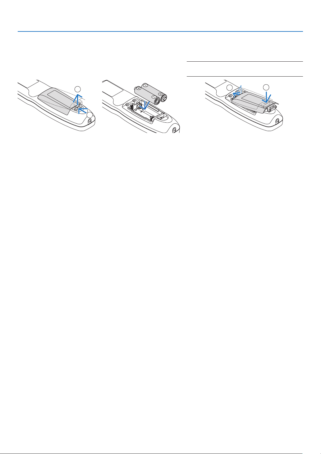
Battery Installation
1. Press the catch and remove
the battery cover.
2. Install new ones (AA). En-
sure that you have the bat-
teries’ polarity (+/−) aligned
correctly.
3. Slip the cover back over the batteries until
it snaps into place.
NOTE:Donotmixdifferenttypesofbatteriesornew
and old batteries.
1
2
1
2
Remote Control Precautions
• Handletheremotecontrolcarefully.
• Iftheremotecontrolgetswet,wipeitdryimmediately.
• Avoidexcessiveheatandhumidity.
• Donotshort,heat,ortakeapartbatteries.
• Donotthrowbatteriesintore.
• Ifyouwillnotbeusingtheremotecontrolforalongtime,removethebatteries.
• Ensurethatyouhavethebatteries’polarity(+/−)alignedcorrectly.
• Donotusenewandoldbatteriestogether,orusedifferenttypesofbatteriestogether.
• Disposeofusedbatteriesaccordingtoyourlocalregulations.
11
1. Introduction
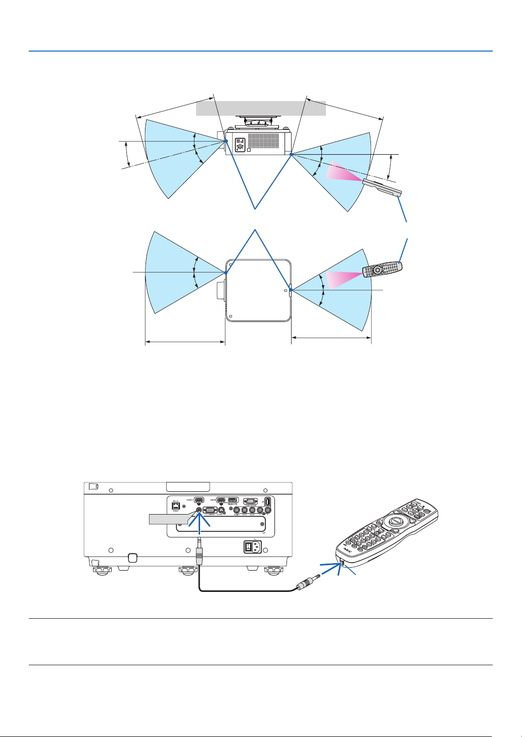
Operating Range for Wireless Remote Control
7
m/276
inch
7m/276inch
Remotecontrol
Remotesensoronprojectorcabinet
7
m/276
inch
7m/276inch
30°
30°
30°
30°
15°
30°
30°
30°
15°
30°
• Theinfraredsignaloperatesbyline-of-sightuptoadistanceofabovemetersandwithina60-degreeangleofthe
remotesensorontheprojectorcabinet.
• Theprojectorwillnotrespondifthereareobjectsbetweentheremotecontrolandthesensor,orifstronglightfalls
onthesensor.Weakbatterieswillalsopreventtheremotecontrolfromproperlyoperatingtheprojector.
Using the Remote Control in Wired Operation
ConnectoneendoftheremotecabletotheREMOTEterminalandtheotherendtotheremotejackontheremote
control.
REMOTE
RemoteJack
NOTE:
• WhenaremotecableisinsertedintotheREMOTEterminal,theremotecontroldoesnotworkforinfraredwirelesscommunication.
• PowerwillnotbesuppliedtotheremotecontrolbytheprojectorviatheREMOTEjack.Batteryisneededwhentheremotecontrol
is used in wired operation.

12
Thissectiondescribeshowtoturnontheprojectorandtoprojectapictureontothescreen.
❶ Flow of Projecting an Image
Step 1
• Connectingyourcomputer/Connectingthepowercord(→ page 13)
Step 2
• Turningontheprojector(→ page 14)
Step 3
• Selectingasource(→ page 16)
Step 4
• Adjustingthepicturesizeandposition(→ page 18)
• Correctingkeystonedistortion[CORNERSTONE](→ page 32)
Step 5
• Adjustingapicture
- Optimizingacomputersignalautomatically(→page23)
Step 6
• Makingapresentation
Step 7
• Turningofftheprojector(→ page 24)
Step 8
• Afteruse(→ page 25)
2. Projecting an Image (Basic Operation)
13
2. Projecting an Image (Basic Operation)
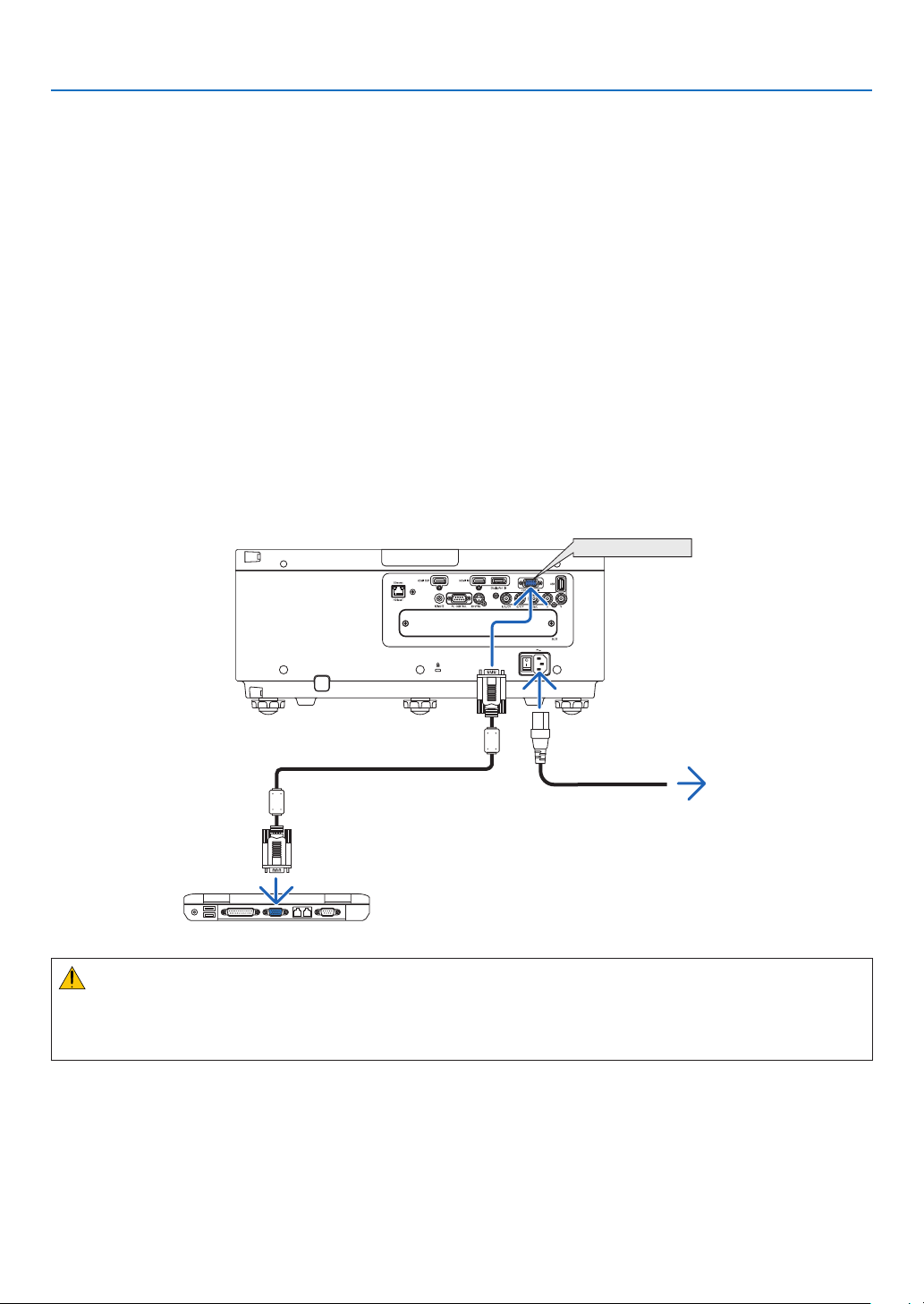
❷ Connecting Your Computer/Connecting the Power Cord
1. Connectyourcomputertotheprojector.
Thissectionwillshowyouabasicconnectiontoacomputer.Forinformationaboutotherconnections,see“(2)
MakingConnections”onpage125.
Connectthedisplayoutputterminal(miniD-sub15pin)onthecomputertotheCOMPUTER1INterminalonthe
projectorwithacommercially-availablecomputercable(withferritecore)andthenturntheknobsoftheterminals
tosecurethem.
2. Connectthesuppliedpowercordtotheprojector.
Firstconnectthesuppliedpowercord’sthree-pinplugtotheACINterminaloftheprojector,andthenconnectthe
otherplugofthesuppliedpowercordinthewalloutlet.
ImportantInformation:
• Whenplugginginorunpluggingthesuppliedpowercord,makesurethatthemainpowerswitchispushedto
theoff[O]position.Failuretodosomaycausedamagetotheprojector.
COMPUTER 1 IN
Makesurethattheprongsarefullyinsertedinto
boththeACINterminalandthewalloutlet.
Towalloutlet
Computercable(withferritecore)
(soldcommercially)
CAUTION:
PartsoftheprojectormaybecometemporarilyheatediftheprojectoristurnedoffwiththePOWERbuttonorifthe
ACpowersupplyisdisconnectedduringnormalprojectoroperation.
Usecautionwhenpickinguptheprojector.
14
2. Projecting an Image (Basic Operation)
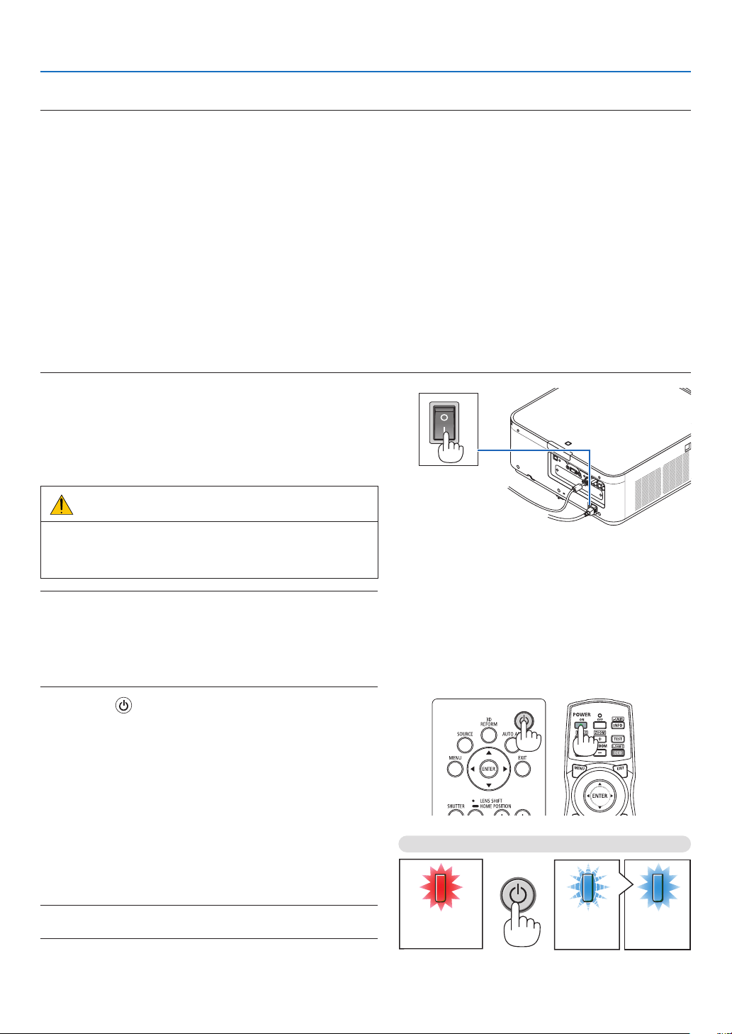
❸ Turning on the Projector
NOTE:
• Theprojectorhastwopowerswitches:AmainpowerswitchandaPOWERbutton(POWERONandOFFontheremotecontrol)
•Turningontheprojector:
1. Press the main power switch to the ON position (I).
Theprojectorwillgointostandbymode.
2. Press the POWER button .
Theprojectorwillbecomereadytouse.
•Turningofftheprojector:
1. Press the POWER button.
Theconrmationmessagewillbedisplayed.
2. Press the POWER button again.
Theprojectorwillgointostandbymode.
3. Press the main power switch to the OFF position (O).
Theprojectorwillbeturnedoff.
1. Press the main power switch to the ON position ( I ).
ThePOWERindicatorlightsupred.*
* ThisindicatesthattheSTANDBYmodeisin[NORMAL]
setting.
(→
page114,168)
WARNING
The projector produces a strong light.When turning on
thepower,makesure no one within projection rangeis
lookingatthelens.
NOTE:
• The[STANDBYMODE]settingwillbedisabledandtheprojector
will go into the sleep mode when the network service is utilized or
theprojectorreceivesHDBaseTsignal.Inthesleepmode,thefans
in the projector rotate for the purpose of interior parts protection.
Pleaserefertopage114 about the sleep mode.
2. Press the (POWER) button on the projector cabinet
or the POWER ON button on the remote control.
ThePOWER indicator goes from a steady red light to
aashingbluelight,andthepicture isprojectedonthe
screen.
TIP:
• Whenthemessage“PROJECTORISLOCKED!ENTERYOUR
PASSWORD.” is displayed, it means that the [SECURITY]
featureisturnedon.(→ page 35)
Afteryouturnonyourprojector,ensurethatthecomputer
orvideosourceisturnedon.
NOTE:Thebluescreen([BLUE]background)isdisplayedwhenno
signalisbeinginput(byfactorydefaultmenusettings).
Standby Blinking Power On
Steady red light Blinking blue
light
Steady blue
light
(→page168)
15
2. Projecting an Image (Basic Operation)
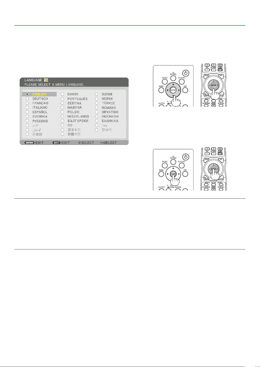
Note on Startup screen (Menu Language Select screen)
Whenyourstturnontheprojector,youwillgettheStartupmenu.Thismenugivesyoutheopportunitytoselectone
ofthe29menulanguages.
Toselectamenulanguage,followthesesteps:
1. Use the ▲, ▼, ◀ or ▶buttontoselectone of the29
languagesfromthemenu.
2. Press the ENTER button to execute the selection.
After this has been done, you can proceed to the menu
operation.
Ifyouwant,youcanselectthemenulanguagelater.
(→[LANGUAGE]onpage66and94)
NOTE:
• Ifoneofthefollowingthingshappens,theprojectorwillnotturnon.
- Iftheinternaltemperatureoftheprojectoristoohigh,theprojectordetectsabnormalhightemperature.Inthisconditionthe
projectorwillnotturnontoprotecttheinternalsystem.Ifthishappens,waitfortheprojector’sinternalcomponentstocool
down.
- IftheSTATUSindicatorlightsorangewiththepowerbuttonpressed,itmeansthatthe[CONTROLPANELLOCK]isturnedon.
Cancelthelockbyturningitoff.(→ page 104)
• WhilethePOWERindicatorisblinkingblueinshortcycles,thepowercannotbeturnedoffbyusingthepowerbutton.(Whilethe
POWERindicatorisblinkingblueinlongcycles,theOFFTIMERisfunctionedandthepowercanbeturnedoff.)
16
2. Projecting an Image (Basic Operation)
❹ Selecting a Source
Selecting the computer or video source
NOTE: Turn on the computer or video source equipment connected to the projector.
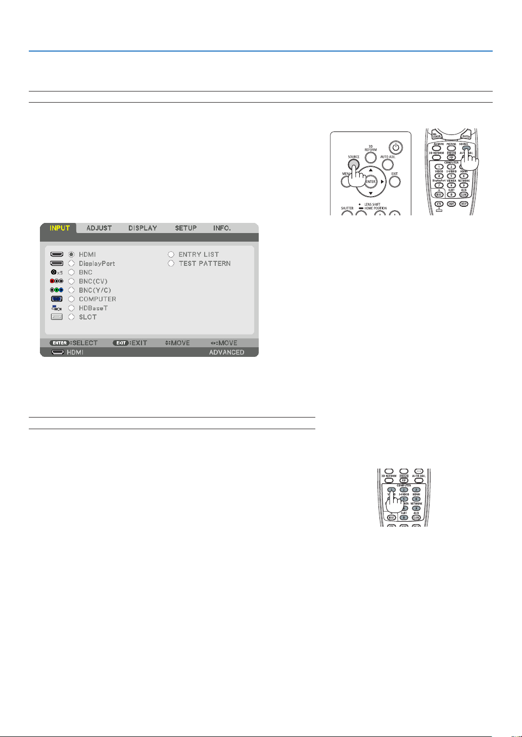
DetectingtheSignalAutomatically
Press the SOURCE button for 1 second or longer.The projector will
searchfortheavailableinputsourceanddisplayit.Theinputsourcewill
changeasfollows:
HDMI→DisplayPort→BNC→BNC(CV)→BNC(Y/C)→COMUPTER
→HDBaseT→SLOT→ …
• Pressitbrieytodisplaythe[INPUT]screen.
Pressthe▼/▲buttonstomatchthetargetinputterminalandthen
presstheENTERbuttontoswitchtheinput.Todeletethemenudisplay
inthe[INPUT]screen,presstheMENUorEXITbutton.
TIP:Ifnoinputsignalispresent,theinputwillbeskipped.
Using the Remote Control
Press any one of the HDMI, DisplayPort, COMPUTER 2,VIDEO, S-
VIDEO,COMPUTER1,NETWORK,orSLOTbuttons.
• COMPUTER2buttonselectstheBNCinputterminal.
• VIDEObuttonselectstheBNC(CV)inputterminal(CompositeVideo).
• S-VIDEObuttonselectstheBNC(Y/C)inputterminal(S-Video).
17
2. Projecting an Image (Basic Operation)
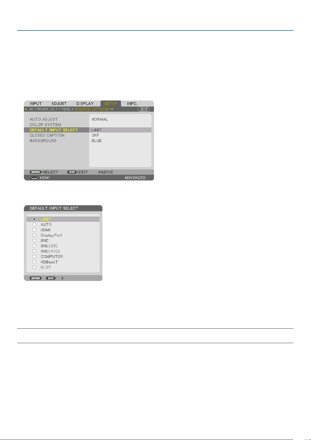
Selecting Default Source
Youcansetasourceasthedefaultsourcesothatitwillbedisplayedeachtimetheprojectoristurnedon.
1. Press the MENU button.
Themenuwillbedisplayed.
2. Press the ▶buttontoselect[SETUP]andpressthe▼buttonortheENTERbuttontoselect[BASIC].
3. Press the ▶buttontoselect[SOURCEOPTIONS].
4. Press the ▼buttonfourtimestoselect[DEFAULTINPUTSELECT]andpresstheENTERbutton.
The[DEFAULTINPUTSELECT]screenwillbedisplayed.
(→page112)
5. Selectasourceasthedefaultsource,andpresstheENTERbutton.
6. Press the EXIT button three times to close the menu.
7. Restart the projector.
Thesourceyouselectedinstep5willbeprojected.
NOTE:Evenwhen[AUTO]isturnedon,the[HDBaseT]willnotbeautomaticallyselected.Tosetyournetworkasthedefaultsource,
select[HDBaseT].
TIP:
• WhentheprojectorisinStandbymode,applyingacomputersignalfromacomputerconnectedtotheCOMPUTER1INinput
willpowerontheprojectorandsimultaneouslyprojectthecomputer’simage.
([AUTOPOWERONSELECT]→ page 115)
• OntheWindows7keyboard,acombinationoftheWindowsandPkeysallowsyoutosetupexternaldisplayeasilyandquickly.
18
2. Projecting an Image (Basic Operation)
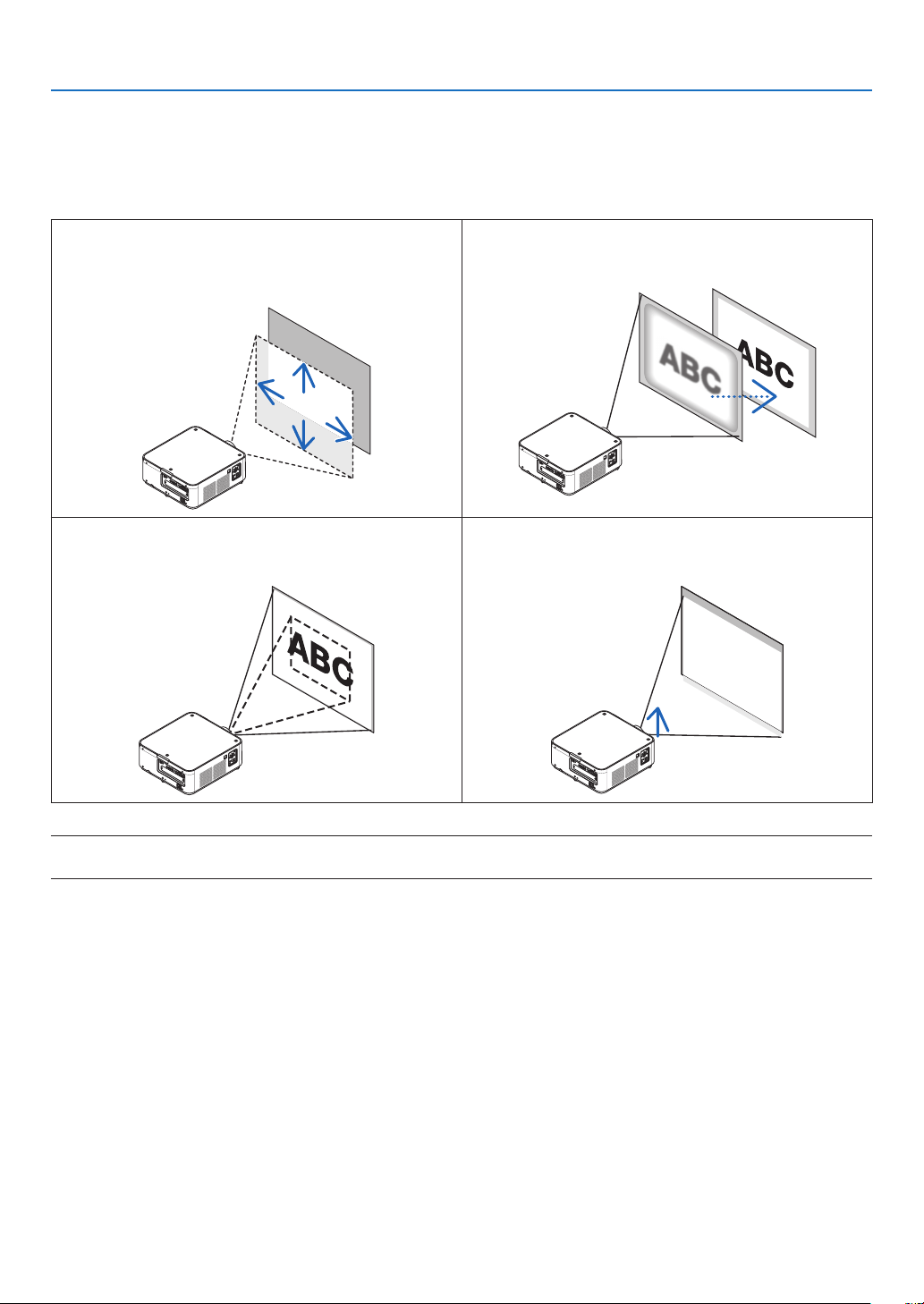
❺ Adjusting the Picture Size and Position
Usethelensshiftdial,theadjustabletiltfootlever,thezoomlever/zoomringandthefocusringtoadjustthepicture
sizeandposition.
Inthischapterdrawingsandcablesareomittedforclarity.
Adjustingthe projected image’svertical and horizontal
position
[Lensshift]
(→page19)
Adjustingthefocus
[Focus]
(→page21)
Finelyadjustingthesizeofanimage
[Zoom]
(→page21)
Adjustingtheprojectedimage’sheightandhorizontaltilt
[Tiltfoot]*¹
(→page23)
NOTE*
1
:Adjusttheprojectedimage’sheightusingthetiltfeetwhenyouwanttoprojecttheimageatapositionhigherthanthelens
shift adjustment range.
19
2. Projecting an Image (Basic Operation)
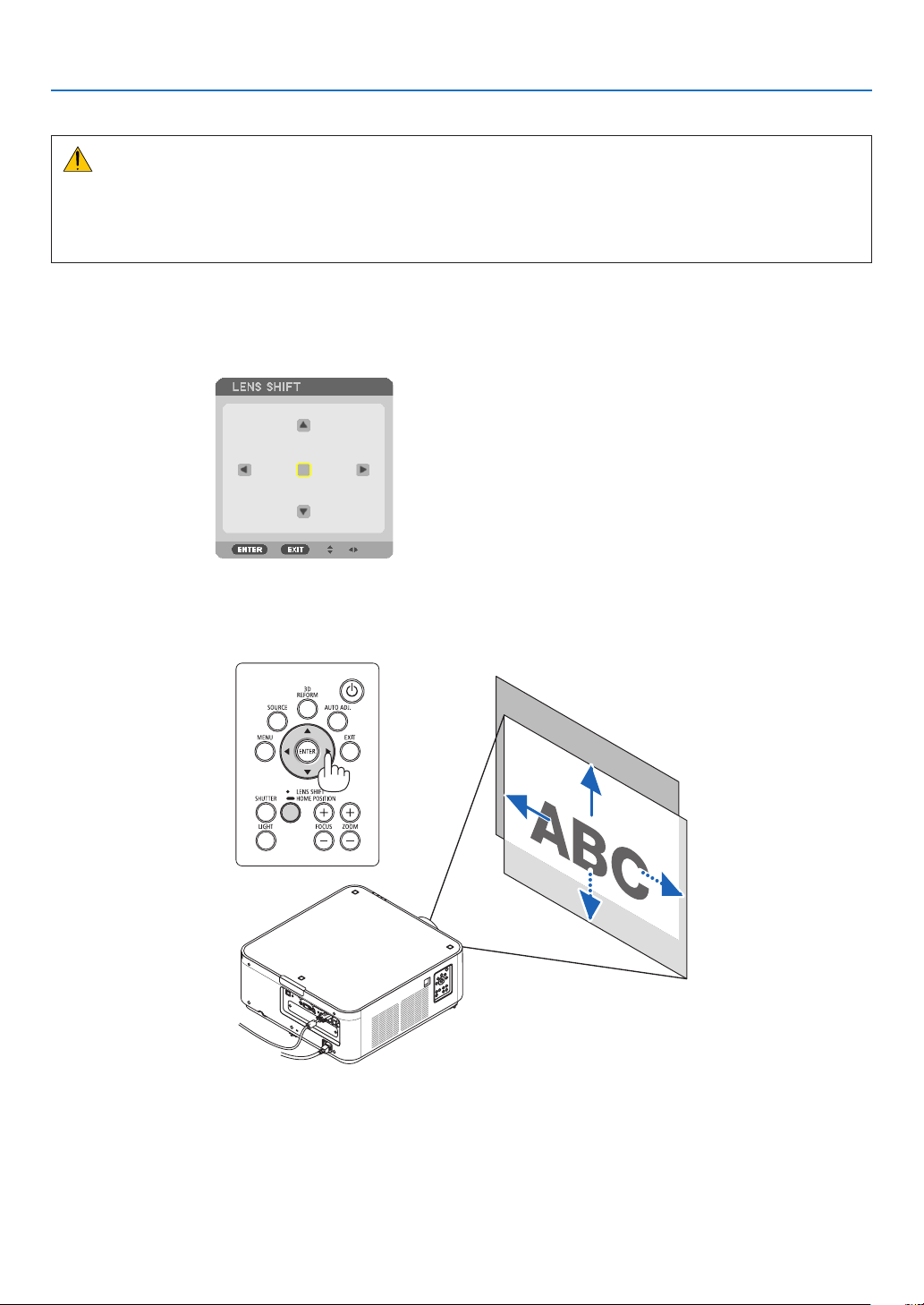
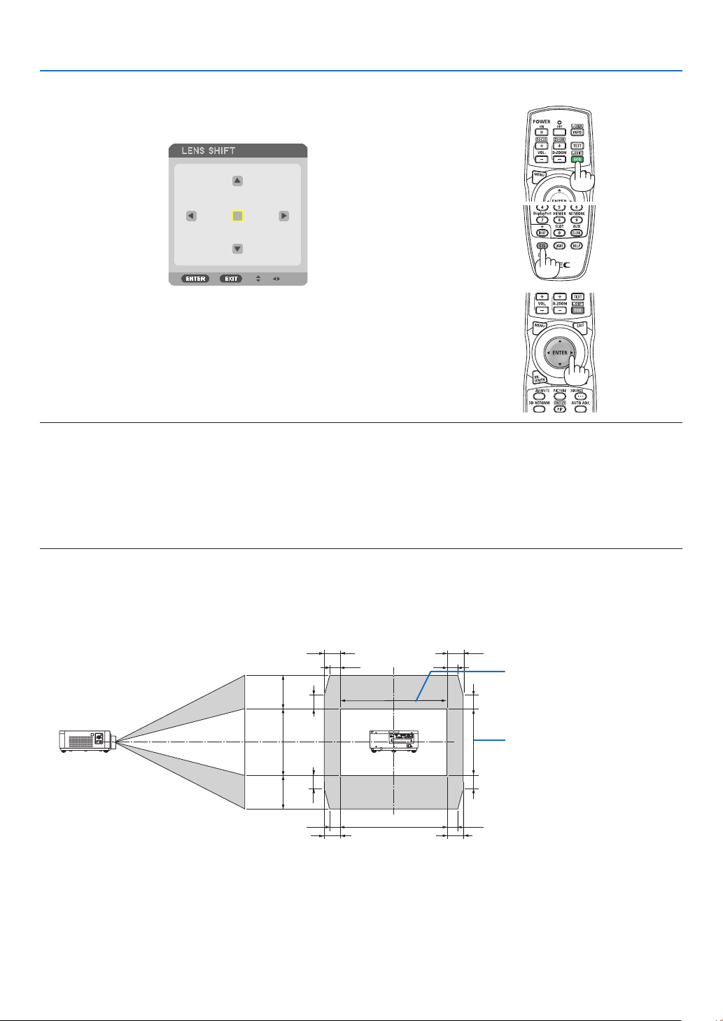
Adjusting the vertical position of a projected image (Lens shift)
CAUTION
• Performtheadjustmentfrombehindorfromthesideoftheprojector.Performingadjustmentfromthefrontcould
exposeyoureyestostronglightwhichcouldinjurethem.
• Keephandsawayfromthelenshoodwhilethelensshiftisinoperation.Failuretodosocouldresultinngers
beingpinchedbetweenthelensandthelenshood.
Adjusting with buttons on the cabinet
1. Press the LENS SHIFT/HOME POSITION button.
The[LENSSHIFT]screenwillbedisplayed.
2. Press the ▼▲◀ or ▶ button.
Usethe▼▲◀▶buttonstomovetheprojectedimage.
• Returningthelensshiftpositiontothehomeposition
PressandholdtheLENSSHIFT/HOMEPOSITIONbuttonfor2secondstoreturnthelensshiftpositiontothe
homeposition(nearlycenterposition)
20
2. Projecting an Image (Basic Operation)
Adjusting with the remote control
1. HoldtheCTLbuttonandpresstheECO/L-SHIFTbutton.
The[LENSSHIFT]screenwillbedisplayed.
2. Press the ▼▲◀ or ▶ button.
Usethe▼▲◀▶buttonstomovetheprojectedimage.
NOTE:
LensCalibration
Ifthepoweroftheprojectoriswronglyshutdownduringthemotionoflensshift,itmayshiftthehomepositionofthelensand
maycauseofmalfunction.Inthiscase,performlenscalibration.
Lenscalibrationprocedures
1.Powerontheprojector.
2.Pressandholdthe(CTL)buttonandpressthe(INFO/L-CALIB.)buttonontheremotecontrol.
Calibrationisperformed.
TIP:
• ThediagrambelowshowsthelensshiftadjustmentrangeforthePX602UL-WHandPX602UL-BK(projectionmode:desktop
front).Toraisetheprojectionpositionhigherthanthis,usethetiltfeet.(→ page 22)
• ForthePX602WL-WH/PX602WL-BKandtheceilingmount/frontprojectionlensshiftadjustmentrange,seepage156.
100%V
50%V
50%V
20%V* 20%V*
20%V*
20%V*
100%H
15%H
15%H
15%H
15%H
10%H
10%H 10%H
10%H
Heightofprojectedimage
Widthofprojectedimage
* 30%VforthePX602WL-WH/PX602WL-BK.
Descriptionofsymbols:Vindicatesvertical(heightoftheprojectedimage),Hindicateshorizontal(widthoftheprojectedimage).
21
2. Projecting an Image (Basic Operation)
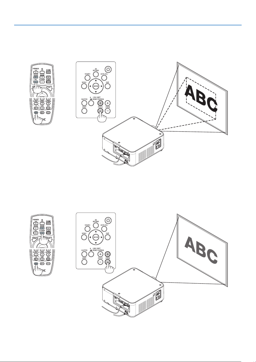
Focus
1. PresstheFOCUS+/−button.
• Ontheremotecontrol,whilepressingontheCTLbutton,pressonVOL/FOCUS(+)or(−)button.
Thefocusisadjusted.
Zoom
1. Press the ZOOM +/− button.
• Ontheremotecontrol,whilepressingontheCTLbutton,presstheD-ZOOM/ZOOM(+)or(−)button.
Thezoomisadjusted.
22
2. Projecting an Image (Basic Operation)
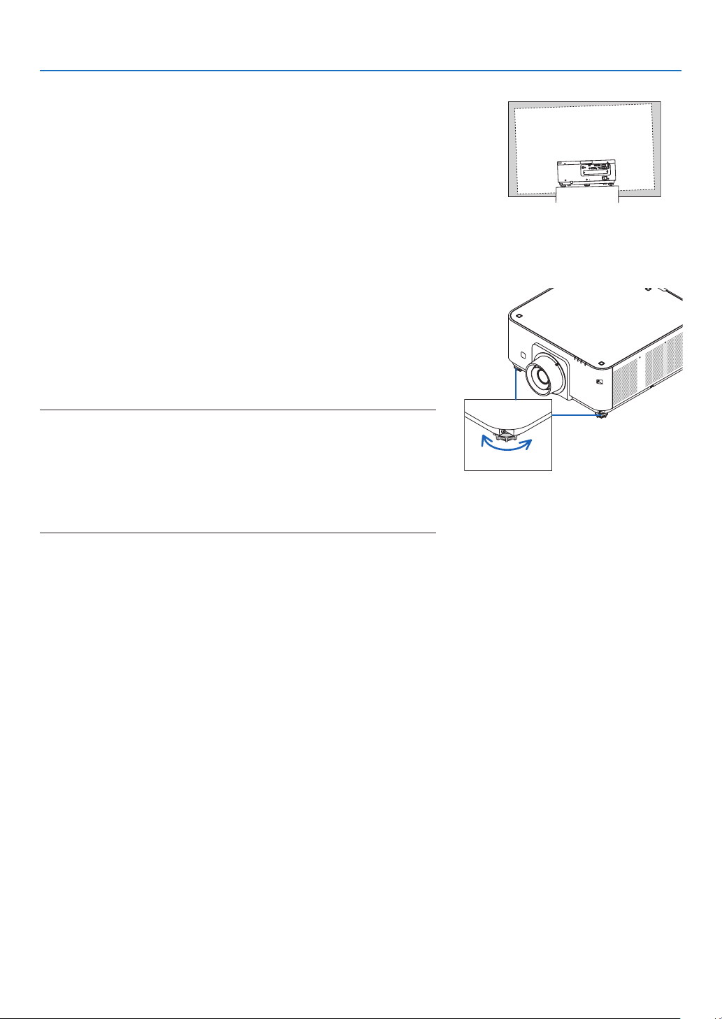
Adjusting the Tilt Foot
1. Theposition to project image may be adjusted bythe tilt feet
positionedatright,leftandrearofthecabinetbottom.
Thetiltfootheightcanbeadjustedbyitsturn.
“Toadjusttheheightoftheprojectedimage”
Theheightoftheprojectedimageisadjustedbyturningtheleftand
righttiltfeet.
“Iftheprojectedimageistilted”
Iftheprojectedimageistilted,turnoneofthetiltfeettoadjustthe
imagesothatitislevel.
“Toadjusttheprojectorsothatitisperpendiculartothescreen”
Turnthereartiltfoottoadjustitsheight.
• Iftheprojectedimageisdistorted,see“3-7CorrectingHorizontal
andVerticalKeystoneDistortion[CORNERSTONE]”(→page32)
and“[GEOMETRICCORRECTION]”(→page100).
• Thetiltfootcanbelengthenedbyamaximumof48mm.
• Thetiltfootcanbeusedtotilttheprojectorbyamaximumof6°.
NOTE:
• Donotlengthenthetiltfootanymorethan50mm/1.9".Doingsowillmakethe
tiltfeet’smountsectionunstableandcouldcausethetiltfeettocomeoffthe
projector.
• Donotusethetiltfootforanypurposeotherthanadjustingtheprojector’s
projection angle.
Handlingthetiltfootimproperly,suchascarryingtheprojectorbygraspingthe
tilt foot or hooking it onto a wall using the tilt foot, could damage the projector.
Up
Tiltfoot
(thereisonemoreintherear)
Down
23
2. Projecting an Image (Basic Operation)
❻ Optimizing Computer Signal Automatically
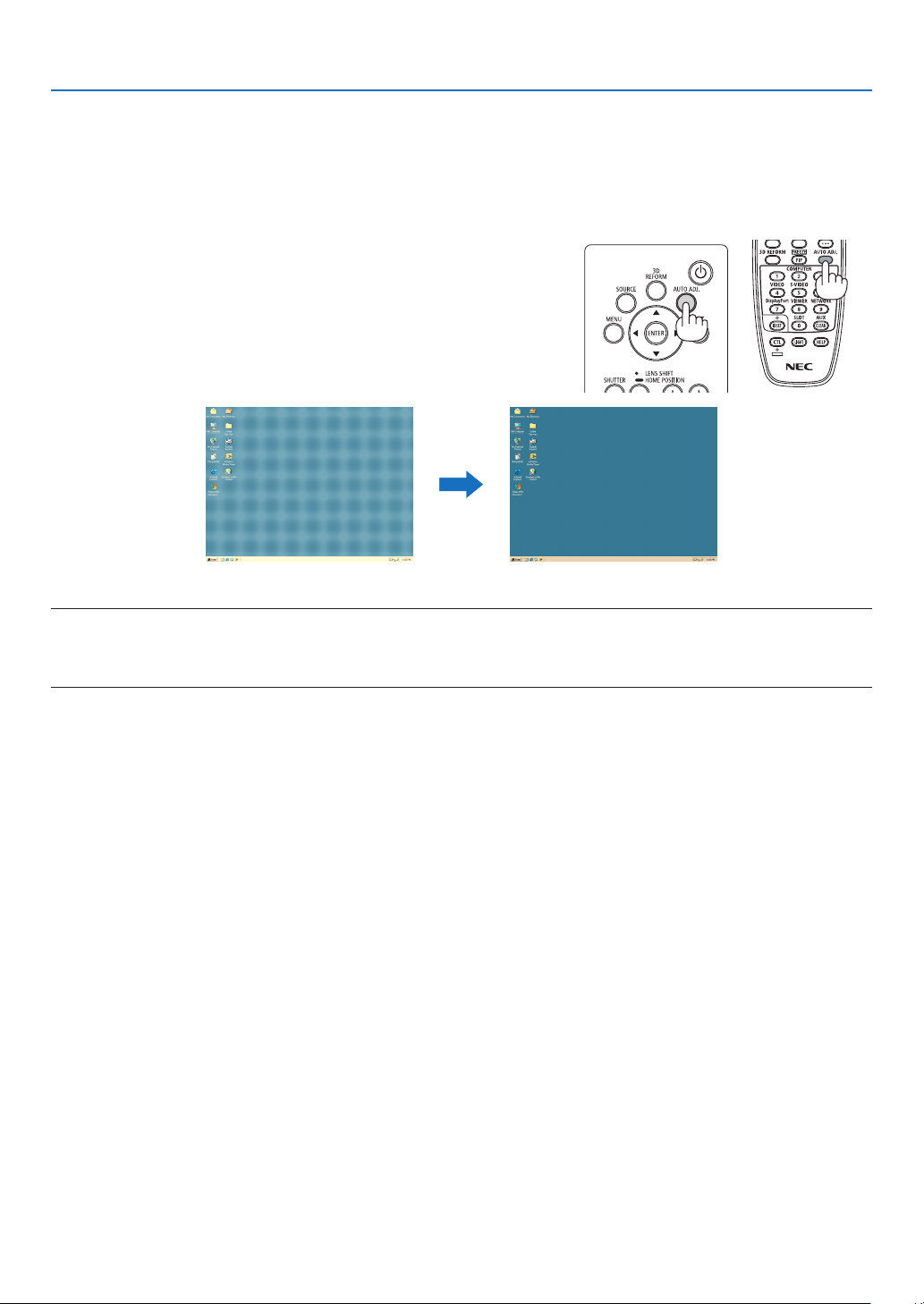
Adjusting the Image Using Auto Adjust
WhenanimagefromHDMIIN,DisplayPortIN,BNCinputterminal(analogRGB),COMPUTER1IN,orHDBaseTis
beingprojected,andtheedgeiscutoffortheimagequalityispoor,thisbuttoncanbeusedtoautomaticallyoptimize
theprojectionimageonthescreen.
PresstheAUTOADJ.buttontooptimizeacomputerimageautomatically.
This adjustmentmaybe necessary when youconnect your computer
forthersttime.
[Poorpicture] [Normalpicture]
NOTE:
Somesignalsmaytaketimetodisplayormaynotbedisplayedcorrectly.
• IftheAutoAdjustoperationcannotoptimizethecomputersignal,trytoadjust[HORIZONTAL],[VERTICAL],[CLOCK],and[PHASE]
manually.(→ page 78, 79)
24
2. Projecting an Image (Basic Operation)
❼ Turning off the Projector
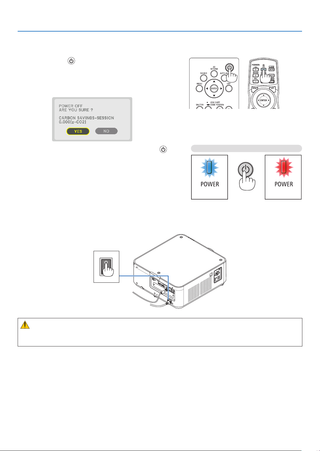
To turn off the projector:
1. First, press the (POWER) button on the projector
cabinet or the POWER OFF button on the remote con-
trol.
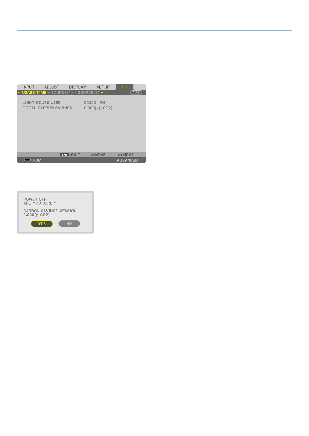
The[POWEROFF/AREYOUSURE?/CARBONSAV-
INGS-SESSION0.000[g-CO2]]messagewillappear.
2. Secondly, press the ENTER button or press the
(POWER) or the POWER OFF button again.
Whentheprojector isin STANDBYMODE,the POWER
indicator lights up red. (When [STANDBY MODE] is in
[NORMAL]setting)
3. Make sure the projector is in STANDBY MODE, then
turnoffthemainpowerswitch(○ OFF)
ThePOWERindicatorwillgooffandthemainpowerwill
turnoff.
• While the POWER indicator is blinking bluein short
cycles,thepowercannotbeturnedoff.
Power On
Steady blue light
Standby
Steady red light
Press twice
CAUTION:
PartsoftheprojectormaytemporarilyoverheatiftheprojectoristurnedoffwiththemainpowerswitchortheAC
powersupplyisdisconnectedwhiletheprojectorisinoperationorthecoolingfanisrunning.Handlewithcare.

25
2. Projecting an Image (Basic Operation)
NOTE:
• Donotunplugthepowercordfromtheprojectororfromthepoweroutletwhileanimageisbeingprojected.Doingsocould
deterioratetheprojector’sACINterminalorthepowerplug’scontact.ToturnofftheACpowersupplywhentheprojectoris
poweredon,usetheprojector’smainpowerswitch,apowerstripequippedwithaswitch,orabreaker.
• DonotturnoffthemainpowerswitchordisconnecttheACpowersupplywithin10secondsofmakingadjustmentsorsetting
changesandclosingthemenu.Doingsocancauselossofadjustmentsandsettings.
❽ After Use
Preparation:Makesurethattheprojectoristurnedoff.
1. Unplug the power cord.
2. Disconnect any other cables.
3. Mount the lens cap on the lens.
4. Beforemovingtheprojector,screwinthetiltfeetiftheyhavebeenlengthened.
26
3. Convenient Features
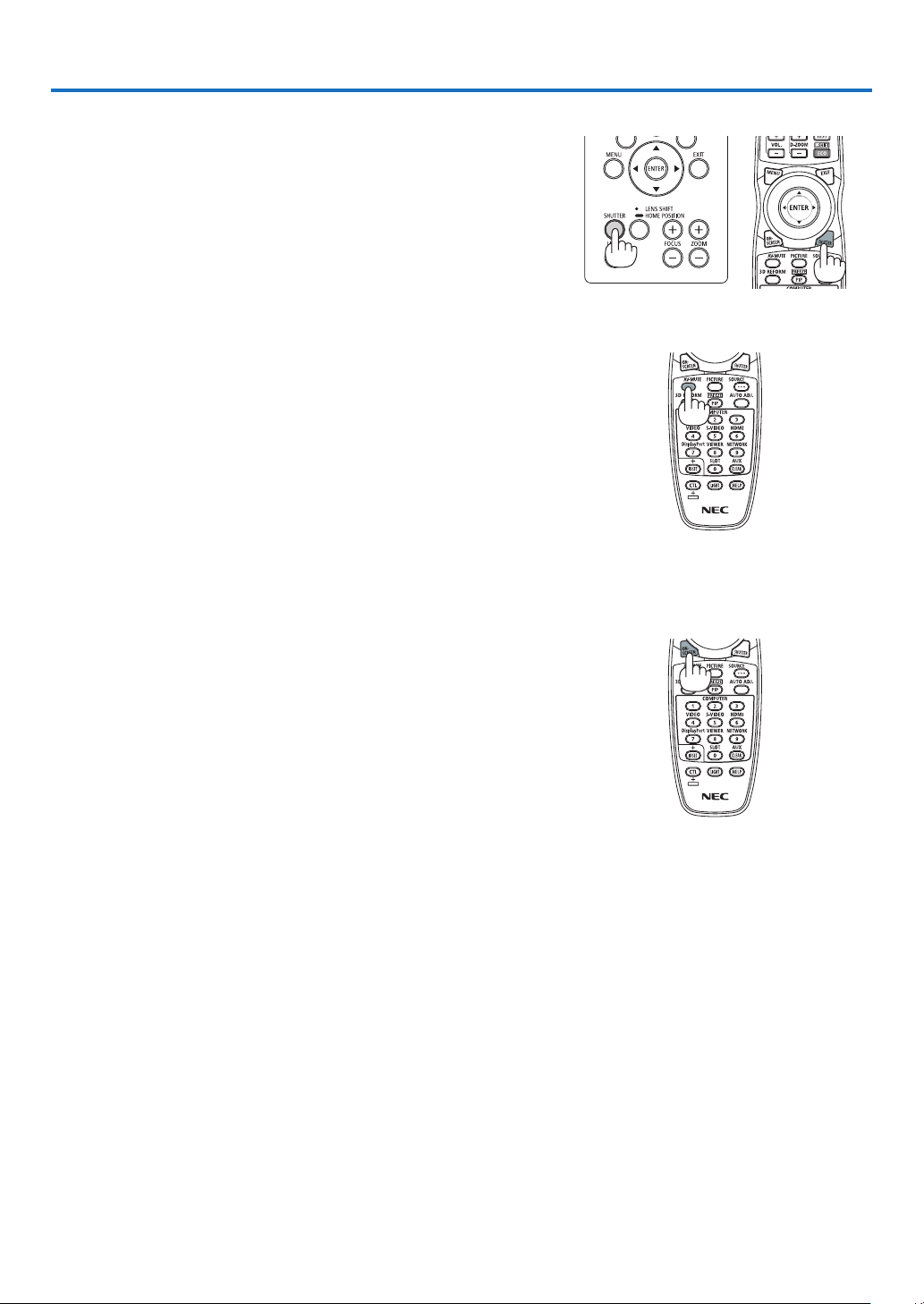
❶ Turn off the light of the projector (LENS SHUTTER)
PresstheSHUTTERbutton.
Thelightsourcewillturnoffandthelightoftheprojectorwilltemporarily
godark.
Pressagaintoallowthescreentobecomeilluminatedagain.
• Anotherwaytoshutthelight sourceoffistopress theSHUTTER
buttonontheremotecontrol.
❷ Turning off the Image
PresstheAV-MUTEbuttontoturnofftheimageforashortperiodoftime.
Pressagaintorestoretheimage.
TIP:
• Thevideowilldisappearbutnotthemenudisplay.
❸ Turning Off the On-Screen Menu (On-Screen Mute)
ApressoftheON-SCREENbuttonontheremotecontrolwillhidethe
on-screenmenu,thesourcedisplayandothermessages.Pressagain
torestorethem.
TIP:
• Toconrmthattheon-screenmuteisturnedon,presstheMENUbutton.Iftheon-screenmenuisnotdisplayedeventhough
youpresstheMENUbutton,itmeanstheon-screenmuteisturnedon.
• Theon-screenmuteismaintainedevenwhentheprojectoristurnedoff,
• HoldingdowntheMENUbuttonforatleast10secondswillturnofftheon-screenmute.

27
3. Convenient Features
❹ Freezing a Picture
HoldtheCTLbuttonandpressthePIP/FREEZEbuttontofreezeapicture.
Pressagaintoresumemotion.
NOTE: The image is frozen but the original video is still playing ahead.
28
3. Convenient Features
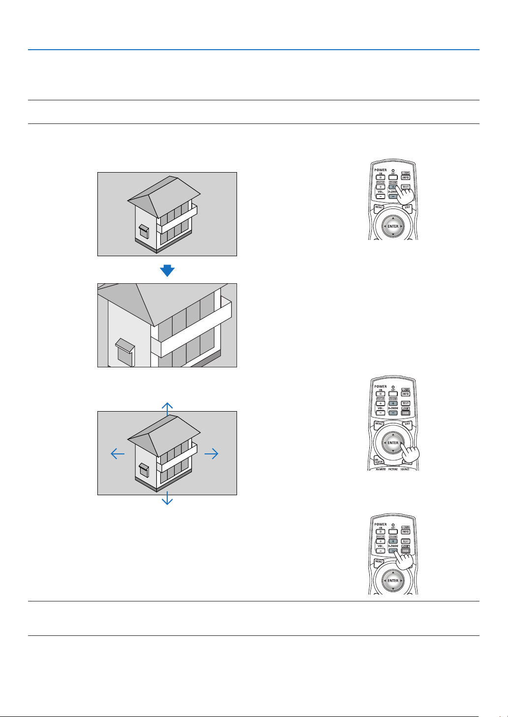
❺ Magnifying a Picture
Youcanmagnifythepictureuptofourtimes.
NOTE:
• Dependingonaninputsignal,themaximummagnicationmaybelessthanfourtimes,orthefunctionmayberestricted.
Todoso:
1. PresstheD-ZOOM(+)buttontomagnifythepicture.
2. Press the ▲▼◀▶ button.
Theareaofthemagniedimagewillbemoved
3. Press the D-ZOOM (−) button.
EachtimetheD-ZOOM(−)buttonispressed,theimageisdemagni-
ed.
NOTE:
• Theimagewillbemagniedordemagniedatthecenterofthescreen.
• Displayingthemenuwillcancelthecurrentmagnication.
29
3. Convenient Features
❻ Changing LIGHT MODE/Checking Energy-Saving Effect
Using LIGHT MODE [LIGHT MODE]
Wheneither[ECO1]or[ECO2]in[LIGHTMODE]isselected,motionnoiseoftheprojectoriscutdownbylowering
brightnessofitslightsource.Bysavingenergyconsumption,theCO
2
emissionfromthisprojectorcanbereduced.
LIGHTMODE
Iconatthebottom
ofthemenu
Description
NORMAL
100%brightness
Thescreenwillbebrightlylit.
ECO1 Brightnesswillbeatabout80%.
Thecoolingfanwillalsoslowdownaccordingly.
Lowerpowerconsumption
ECO2 Brightnesswillbeatabout50%.
Thecoolingfanwillalsoslowdownaccordingly.
Lowerpowerconsumptionconsiderably
* Whenthebrightnessislowered,thecoolingfanspeedwillbereducedaccordingly.
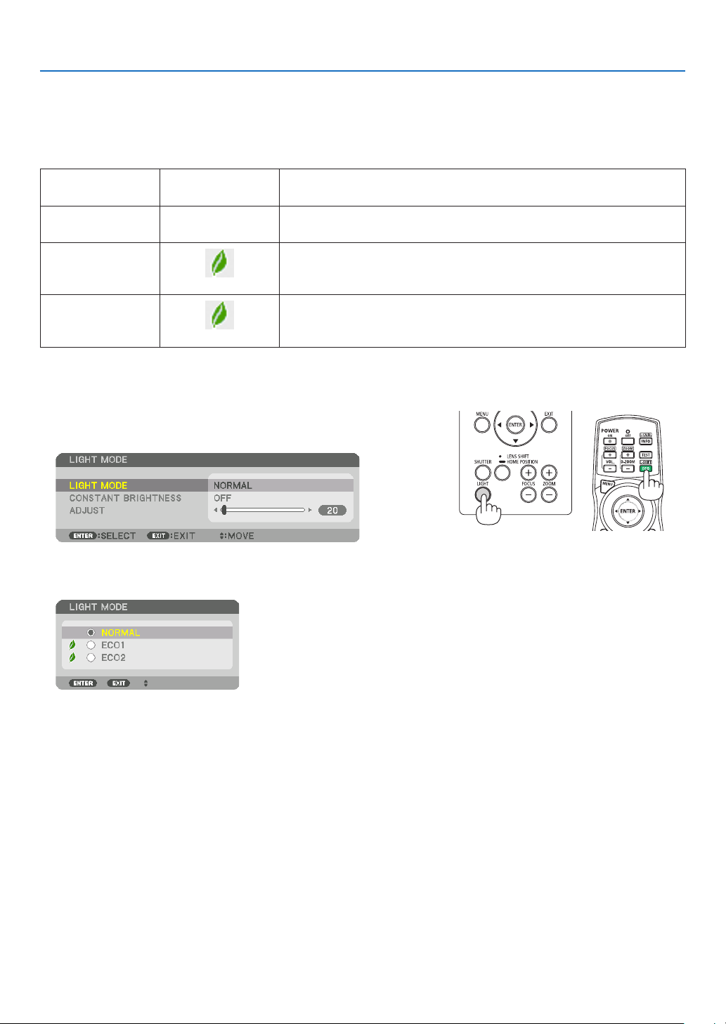
Toturnonthe[LIGHTMODE],dothefollowing:
1. Press LIGHT button on the cabinet.
• Inanotherway,pressECO/L-SHIFTbuttonontheremotecontrol.
The[LIGHTMODE]screenwillbedisplayed.
2. Press the ENTER button.
The[LIGHTMODE]selectionscreenwillbedisplayed.
3. Use the ▼▲ buttons to make a selection, and press the ENTER
button.
Thedisplaywillreturntothe[LIGHTMODE]screenandtheselected
optionwillbeapplied.
PresstheMENUbuttontoreturntotheoriginalscreen.

30
3. Convenient Features
NOTE:
• The[LIGHTMODE]canbechangedbyusingthemenu.
Select[SETUP]→[INSTALLATION]→[LIGHTMODE]→[LIGHTMODE].
• Thelightmodulehoursusedcanbecheckedin[USAGETIME].Select[INFO.]→[USAGETIME].
• Afteralapseof1minutefromwhentheprojectordisplaysablue,blackorlogoscreen,[LIGHTMODE]willautomaticallyswitch
to[ECO].
• Iftheprojectorisoverheatedin[NORMAL]mode,theremaybeacasewherethe[LIGHTMODE]automaticallychangesto[ON]
modetoprotecttheprojector.Thisiscalled“ForcedLIGHTMODE”.WhentheprojectorisintheForcedLIGHTMODE,thepicture
brightnessdecreasesslightlyandtheTEMP.indicatorlightsorange.AtthesametimetheThermometersymbol[ ]isdisplayed
at the bottom right of the screen.
Whentheprojectorcomesbacktonormaltemperature,theForcedLIGHTMODEiscancelledandthe[LIGHTMODE]returnsto
[NORMAL]mode.
31
3. Convenient Features
Checking Energy-Saving Effect [CARBON METER]
Thisfeaturewillshowenergy-savingeffectintermsofCO
2
emissionreduction(kg)whentheprojector’s[LIGHTMODE]
issettoeither[ECO1]or[ECO2].Thisfeatureiscalledas[CARBONMETER].
Therearetwomessages:[TOTALCARBONSAVINGS]and[CARBONSAVINGS-SESSION].The[TOTALCARBON
SAVINGS]messageshowsthetotalamountofCO
2
emissionreductionfromthetimeofshipmentuptonow.Youcan
checktheinformationon[USAGETIME]from[INFO.]ofthemenu.(→page117)
The[CARBONSAVINGS-SESSION]messageshowstheamountofCO
2
emissionreductionbetweenthetimeof
changingtoLIGHTMODEimmediatelyafterthetimeofpower-onandthetimeofpower-off.The[CARBONSAVINGS-
SESSION]messagewillbedisplayedinthe[POWEROFF/AREYOUSURE?]messageatthetimeofpower-off.
TIP:
• TheformulashownbelowisusedtocalculatetheamountofCO
2
emissionreduction.AmountofCO
2
emissionreduction=(Power
consumptionin[NORMAL]LIGHTMODE–Powerconsumptionincurrentsetting)×CO
2
conversionfactor.*Whenanenergy-
savingLIGHTMODEisselected,ortheLensShutterisused,therewillbeafurtherreductioninCO
2
emission.
* CalculationforamountofCO
2
emissionreductionisbasedonanOECDpublication“CO
2
EmissionsfromFuelCombustion,
2008Edition”.
• The[TOTALCARBONSAVINGS]iscalculatedbasedonsavingsrecordedin15minutesintervals.
• Thisformulawillnotapplytothepowerconsumptionwhichisnotaffectedbywhether[LIGHTMODE]isturnedonoroff.
32
3. Convenient Features
❼ Correcting Horizontal and Vertical Keystone Distortion
[CORNERSTONE]
Usethe[CORNERSTONE]featuretocorrectkeystone(trapezoidal)distortiontomakethetoporbottomandtheleft
orrightsideofthescreenlongerorshortersothattheprojectedimageisrectangular.
1. Pressandholdthe3DREFORMbuttonfor2secondsatleasttoresetcurrentadjustments.
Currentadjustmentsfor[GEOMETRICCORRECTION]willbecleared.
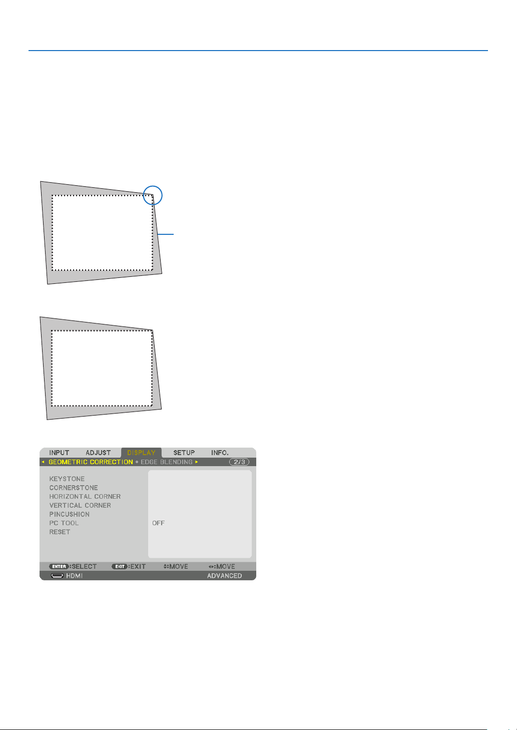
2. Projectanimagesothatthescreenissmallerthantheareaoftheraster.
Projectedimage
Thedrawingshowstheupperrightcorner.
3. Pickupanyoneofthecornersandalignthecorneroftheimagewithacornerofthescreen.
4. Press the 3D REFORM button.
Displaythe[GEOMETRICCORRECTION]screenoftheon-screenmenu.
33
3. Convenient Features
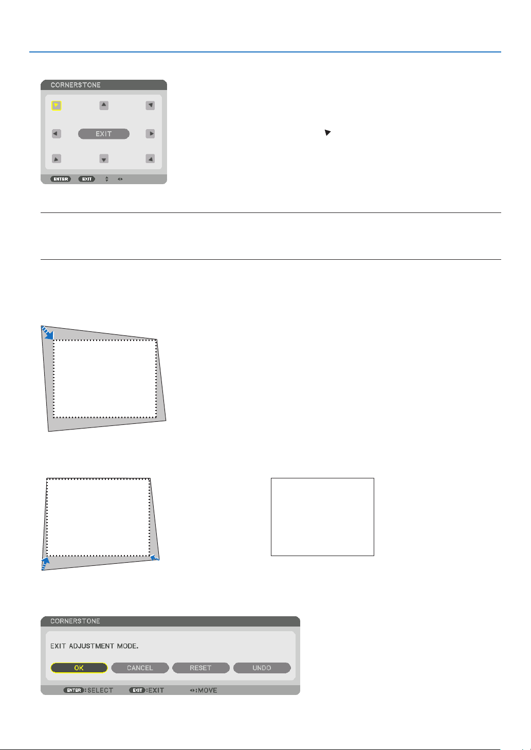
5. Press the ▼buttontoalignwiththe[CORNERSTONE]andthenpresstheENTERbutton.
Thedrawingshowstheupperlefticon( )isselected.
Thescreenwillswitchtothe[CORNERSTONE]screen.
NOTE:
• Whena[GEOMETRICCORRECTION]functionotherthan[CORNERSTONE]hasbeensetup,the[CORNERSTONE]screen
willnotbedisplayed.Whenthescreenisnotdisplayed,eitherpressthe3DREFORMbuttonfor2ormoreseconds,orrun
[RESET]in[GEOMETRICCORRECTION]tocleartheadjustmentvalueof[GEOMETRICCORRECTION].
6. Use the ▲▼◀▶ button to select one icon (▲) which points in the direction you wish to move the projected
imageframe.
7. Press the ENTER button.
8. Use the ▲▼◀▶buttontomovetheprojectedimageframeasshownontheexample.
9. PresstheENTERbutton.
10
. Use the ▲▼◀▶ button to select another icon which points in the direction.
11
.Repeatstepsfrom7to10tocompletethecornerstoneadjustment.
12
.Onthe[CORNERSTONE]screen,select[EXIT]orpresstheEXITbuttonontheremotecontrol.
Theconrmationscreenisdisplayed.

34
3. Convenient Features
13
. Press the ◀ or ▶buttontohighlightthe[OK]andpresstheENTERbutton.
Thiscompletesthe[CORNERSTONE]correction.
• Returningtothe[CORNERSTONE]screen,select[CANCEL]andpresstheENTERbutton.
NOTE:
• Evenwhentheprojectoristurnedon,thelastusedcorrectionvaluesareapplied.
• Carryouteitheroneofthefollowingactionstocleartheadjustmentvalueof[CORNERSTONE].
• InStep12,select[RESET]andthenpresstheENTERbutton.
• Pressthe3DREFORMbuttonfor2ormoreseconds.
• Run[DISPLAY]→[GEOMETRICCORRECTION]→[RESET]intheon-screenmenu.
• UsingCORNERSTONEcorrectioncancausetheimagetobeslightlyblurredbecausethecorrectionismadeelectronically.
35
3. Convenient Features
❽
Preventing the Unauthorized Use of the Projector [SECURITY]
AkeywordcanbesetforyourprojectorusingtheMenutoavoidoperationbyanunauthorizeduser.Whenakeyword
isset,turningontheprojectorwilldisplaytheKeywordinputscreen.Unlessthecorrectkeywordisentered,thepro-
jectorcannotprojectanimage.
•The[SECURITY]settingcannotbecancelledbyusingthe[RESET]ofthemenu.
ToenabletheSecurityfunction:
1. Press the MENU button.
Themenuwillbedisplayed.
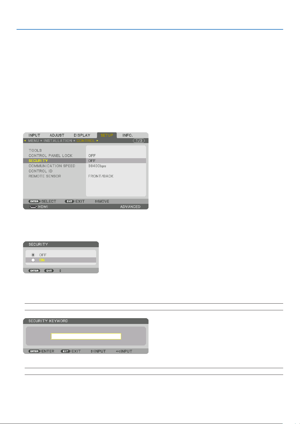
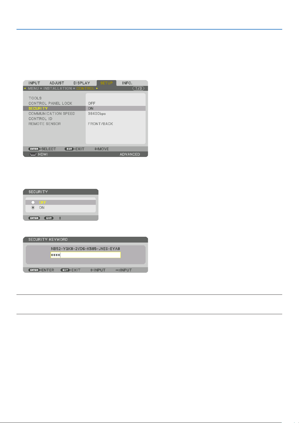
2. Press the ▶buttontwicetoselect[SETUP]andpressthe▼buttonortheENTERbuttontoselect[MENU].
3. Press the ▶buttontoselect[CONTROL].
4. Press the ▼buttonthreetimestoselect[SECURITY]andpresstheENTERbutton.
TheOFF/ONmenuwillbedisplayed.
5. Press the ▼buttontoselect[ON]andpresstheENTERbutton.
The[SECURITYKEYWORD]screenwillbedisplayed.
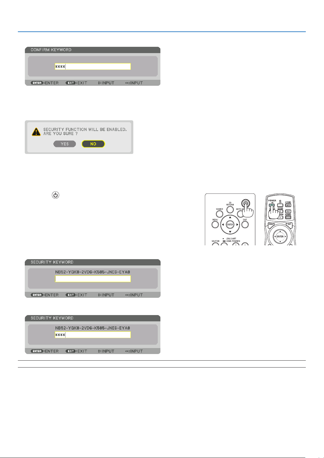
6. Typeinacombinationofthefour▲▼◀▶ buttons and press the ENTER button.
NOTE:Akeywordmustbe4to10digitsinlength.
The[CONFIRMKEYWORD]screenwillbedisplayed.
NOTE:Makeanoteofyourpasswordandstoreitinasafeplace.
36
3. Convenient Features
7. Typeinthesamecombinationof▲▼◀▶ buttons and press the ENTER button.
Theconrmationscreenwillbedisplayed.
8. Select[YES]andpresstheENTERbutton.
TheSECURITYfunctionhasbeenenabled.
Toturnontheprojectorwhen[SECURITY]isenabled:
1. Press the button.
• Ifusingtheremotecontrol,pressthePOWERONbutton.
Theprojectorwillbeturnedonanddisplayamessagetotheeffect
thattheprojectorislocked.
2. Press the MENU button.
3. Type in the correct keyword and press the ENTER button. The projector will display an image.
NOTE: The security disable mode is maintained until the main power is turned off or unplugging the power cord.
37
3. Convenient Features
TodisabletheSECURITYfunction:
1. Press the MENU button.
Themenuwillbedisplayed.
2. Select[SETUP]→[CONTROL]→[SECURITY]andpresstheENTERbutton.
TheOFF/ONmenuwillbedisplayed.
3. Select[OFF]andpresstheENTERbutton.
TheSECURITYKEYWORDscreenwillbedisplayed.
4. Type in your keyword and press the ENTER button.
Whenthecorrectkeywordisentered,theSECURITYfunctionwillbedisabled.
NOTE:Ifyouforgetyourkeyword,contactyourdealer.Yourdealerwillprovideyouwithyourkeywordinexchangeforyourrequest
code.YourrequestcodeisdisplayedintheKeywordConrmationscreen.Inthisexample[NB52-YGK8-2VD6-K585-JNE6-EYA8]
is a request code.
38
3. Convenient Features
❾ Projecting 3D videos
ThisprojectorsupportsDLP-Linkglassesand3Demitter.
CAUTION
Health precautions
Beforeuse,pleasemakesuretoreadanyhealthprecautionsthatmaybestatedintheoperatingmanualsenclosed
withthe3Deyewearand3Dvideosoftware(Blu-rayplayer,games,computeranimationles,etc.).
Pleasetakenoteofthefollowinginordertoavoidadversehealtheffects.
• Pleasedonotusethe3Deyewearforpurposesotherthantowatch3Dvideos.
• Pleasekeepadistanceofatleast2mawayfromthescreenwhenwatchingvideos.Watchingavideotooclose
tothescreenwillincreaseeyefatigue.
• Pleasedonotwatchvideoscontinuouslyforalongperiodoftime.Pleasetakea15minutes’breakafterevery
hourofwatching.
• Pleaseconsultadoctorbeforewatchingifyouoranyofyourfamilymembershaveahistoryofsufferingfrom
seizurescausedbylightsensitivity.
• Pleasestopwatchingimmediatelyandtakearestwhenyoufeelphysicallyunwellwhilewatching(vomiting,gid-
diness,nausea,headaches,soreeyes,blurredvision,crampsanddumbnessinthelimbs,etc.).Pleaseconsult
adoctorifthesymptomspersist.
• Pleasewatcha3Dvideodirectlyinfrontofthescreen.Ifyouwatcha3Dvideoobliquelyfromthesides,thismay
resultinphysicalandeyefatigue.
Procedure to watch 3D videos using this projector
ThedescriptionhereareforDLP
®
Link.[DLP®Link]isdefaultsettingfor[3DGLASSES]atthefactory.
3Deyewearand3Demitterpreparations
UseDLP
®
Linkglassesorothercompatiblecommercially-availableliquidcrystalshutterspectacles.
1. Connectthevideodevicetotheprojector.
2. Switch on the projector.
3. Runthe3Dvideosoftware.
The3Dvideowillbeprojected.
Thedefaultfactorysettingis[AUTO].When3Dimageisnotprojected,itmaycauseinputsignaldoesnotcontain
3Ddetectionsignaloritcannotbedetectedbythisprojector.Inthiscase,pleasesetuptheformatmanually.
(1)PresstheMENUbutton.
TheMENUwillbedisplayed.
(2)Pressthe▶button,select[ADJUST],thenpressENTER.
[PICTURE]willbehighlighted.
(3)Usethe▶buttontoselect[3DSETTINGS].
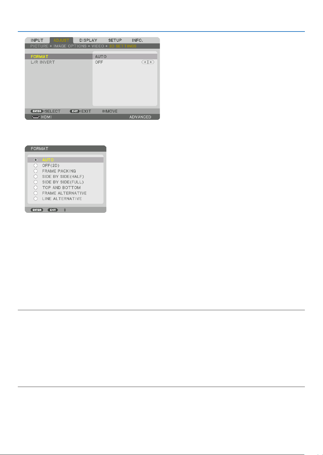
39
3. Convenient Features
The[3DSETTINGS]screenwillbedisplayed.
(4)Usethe▼buttontoalignthecursorwith[FORMAT],thenpressENTER.
The[FORMAT]screenwillbedisplayed.
(5)Usethe▼/▲buttonstoalignthecursoratoneamongformatoptions,thenpressENTERforsettingitup.
Thedisplaywillreturntothe[FORMAT]screen.
PresstheMENUbuttontoreturntotheoriginalscreen.
• The3Dcautionmessagescreenwillbedisplayedwhenswitchingtoa3Dvideo(defaultfactorysettingwhen
shipped).Pleasereadthe“HealthPrecautions”onthepreviouspagetowatchvideosinthecorrectmanner.The
screenwilldisappearafter60secondsorwhentheENTERbuttonispressed.(→page95)
4. Turnonthepowersupplyofthe3Deyewearandweartheeyeweartowatchthevideo.
Anormalvideowillbeshownwhena2Dvideoisinput.
Towatcha3Dvideoin2D,select[OFF(2D)]inthe[FORMAT]screenmentionedabovein(3).
NOTE:
• If3Dcontentisplayedbackonyourcomputerandtheperformanceispoor,itmaybecausedbytheCPUorgraphicschip.Inthis
caseyoumayhavedifcultyseeingthe3Dimagesastheywereintended.Checktoseeifyourcomputermeetstherequirements
providedinyouruser’smanualincludedwithyour3Dcontent.
• TheDLP
®
Linkcompatible3Deyeglassesallowyoutoview3Dimagesbyreceivingsynchsignals,whichareincludedinlefteye
andrighteyeimages,reectedfromthescreen.Dependingonenvironmentsorconditionssuchastheambientbrightness,screen
sizeorviewingdistance,the3Deyeglassesmayfailtoreceivesynchsignals,causingpoor3Dimages.
• Whenthe3Dmodeisenabled,theKeystonecorrectionrangewillbenarrower.
• Whenthe3Dmodeisenabled,thefollowingsettingsareinvalid.
[WALLCOLOR],[PRESET],[REFERENCE],[COLORTEMPERATURE],[DYNAMICCONTRAST],[BrilliantColor]
• Signalsotherthanthoselistedin“CompatibleInputSignalList”onpage160 and 161willbeoutofrangeordisplayedin2D.

40
3. Convenient Features
Using a 3D emitter
Thisprojectorcanbeusedtowatchvideosin3Dusingcommercially-availableactiveshutter-type3Deyewear.In
ordertosynchronizethe3Dvideoandeyewear,acommercially-available3Demitterneedstobeconnectedtothe
projector(ontheprojectorside).
The3Deyewearreceivesinformationfromthe3Demitterandperformsopeningandclosingontheleftandright.
3Deyewearand3Demitterpreparations
Pleaseuseanactiveshutter-type3DeyewearthatconformswiththeVESAstandard.
Acommercially-availableRFtypemadebyXpandisrecommended.
3D eyewear ������������ Xpand X105-RF-X2
3D emitter
�������������� Xpand AD025-RF-X1
Connectyour3Demittertothe3DSYNCterminaloftheprojector.
Change[3DGLASSES]settingto[OTHERS].
NOTE:
• Uponswitchingto3Dimage,thefollowingfunctionswillbecancelledanddisabled.[BLANKING],[PIP/PICTUREBYPICTURE],
[GEOMETRICCORRECTION],[EDGEBLENDING]([GEOMETRICCORRECTION]and[EDGEBLENDING]adjustmentvalueswill
bemaintained.)
• Theoutputmaynotautomaticallyswitchtoa3Dvideodependingonthe3Dinputsignal.
• ChecktheoperatingconditionsdescribedintheusermanualoftheBlu-rayplayer.
• PleaseconnecttheDINterminalofthe3Demittertothe3DSYNCofthemainprojector.
• The3Deyewearallowsvideostobeviewedin3Dbyreceivingsynchronizedopticalsignalsoutputfromthe3Demitter.
Asaresult,the3Dimagequalitymaybeaffectedbyconditionssuchasthebrightnessofthesurroundings,screensize,viewing
distance, etc.
• Whenplayinga3Dvideosoftwareonacomputer,the3DimagequalitymaybeaffectedifthecomputerCPUandgraphicschip
performancearelow.Pleasechecktherequiredoperatingenvironmentofthecomputerthatisstatedintheoperatingmanual
attachedtothe3Dvideosoftware.
• Dependingonthesignal,[FORMAT]and[L/RINVERT]maynotbeabletobeselected.Pleasechangethesignalinthatcase.

41
3. Convenient Features
When videos cannot be viewed in 3D
Pleasecheckthefollowingpointswhenvideoscannotbeviewedin3D.
Pleasealsoreadtheoperatingmanualattachedtothe3Deyewear.
Possiblereasons Solutions
The selected signal does not support 3D output� Please change the video signal input to one that supports 3D�
The format for the selected signal is turned to [OFF(2D)]� Please change the format in the on-screen menu to [AUTO] or a
format that supports 3D�
A eyewear that is not supported by the projector is being used� Please purchase a commercially-available 3D eyewear or 3D emit-
ter (recommended)� (→ page 40)
Please check the following points when a video cannot be viewed
in 3D using a 3D eyewear that is supported by the projector�
The power supply of the 3D eyewear is turned off� Please turn on the power supply of the 3D eyewear�
The internal battery of the 3D eyewear is flat� Please charge or replace the battery�
The viewer is located too far away from the screen� Please get closer to the screen until the video can be seen in 3D�
Please turn the L/R INVERT in the on-screen menu to [OFF]�
Due to multiple 3D projectors working at the same time in the
vicinity, the projectors may interfere with one another� Alter-
natively, there may be a bright light source near the screen�
Please maintain sufficient distance between the projectors�
Please keep the light source away from the screen�
Please turn the L/R INVERT in the on-screen menu to [OFF]�
Please check the following points when videos played back on the
computer cannot be viewed in 3D�
Settings on the computer are not compatible with 3D video
playback�
Check to make sure that settings on the computer meet require-
ments for 3D video playback�
Image resolution on the computer cannot be recognized by
the projector as 3D video�
Change the image resolution on the computer to one that the
projector can recognize as 3D video�
The vertical scan rate on the computer cannot be recognized
by the projector as 3D video�
Change the vertical scan rate on the computer to 60 Hz or 120 Hz�
There is an obstacle between the optical receiver of the 3D eye-
wear and the 3D emitter�
Please remove the obstacle�
The 3D format of the 3D video contents is not supported� Please check with the company selling the 3D video contents�

42
3. Convenient Features
❿ Controlling the Projector by Using an HTTP Browser
Overview
TheHTTPServerfunctionprovidessettingsandoperationsfor:
1. Settingforwirednetwork(NETWORKSETTINGS)
TousewiredLANconnection,connecttheprojectortothecomputerwithacommerciallyavailableLANcable.(→
page133)
2. Setting Alert Mail (ALERT MAIL)
Whentheprojectorisconnectedtoawirednetwork,errormessageswillbesentviae-mail.
3. Operating the projector
Poweron/off,selectinginput,volumecontrolandpictureadjustmentsarepossible.
4. SettingPJLinkPASSWORDandAMXBEACON
AccesstotheHTTPserverfunctionisavailable:
• StarttheWebbrowseronthecomputerviathenetworkconnectedtotheprojectorandenterthefollowing
URL :
http://<the projector’s IP address> /index.html
TIP:ThefactorysettingIPaddressis[DHCPON].
NOTE:
• Tousetheprojectorinanetwork,consultwithyournetworkadministratoraboutnetworksettings.
• Thedisplay’sorbutton’sresponsecanbesloweddownoroperationmaynotbeaccepteddependingthesettingsofyournetwork.
Shouldthishappen,consultyournetworkadministrator.Theprojectormaynotrespondifitsbuttonsarerepeatedlypressedin
rapidintervals.Shouldthishappen,waitamomentandrepeat.Ifyoustillcan’tgetanyresponse,turnoffandbackontheprojec-
tor.
• IfthePROJECTORNETWORKSETTINGSscreendoesnotappearinthewebbrowser,presstheCtrl+F5keystorefreshyourweb
browser(orclearthecache).
• Thisprojectoruses“JavaScript”and“Cookies”andthebrowsershouldbesettoacceptthesefunctions.Thesettingmethodwill
varydependingontheversionofbrowser.Pleaserefertothehelplesandtheotherinformationprovidedinyoursoftware.
Preparation before Use
ConnecttheprojectortoacommerciallyavailableLANcablebeforeengaginginbrowseroperations.(→page133)
Operationwithabrowserthatusesaproxyservermaynotbepossibledependingonthetypeofproxyserverandthe
settingmethod.Althoughthetypeofproxyserverwillbeafactor,itispossiblethatitemsthathaveactuallybeenset
willnotbedisplayeddependingontheeffectivenessofthecache,andthecontentssetfromthebrowsermaynotbe
reectedinoperation.Itisrecommendedthataproxyservernotbeusedunlessitisunavoidable.
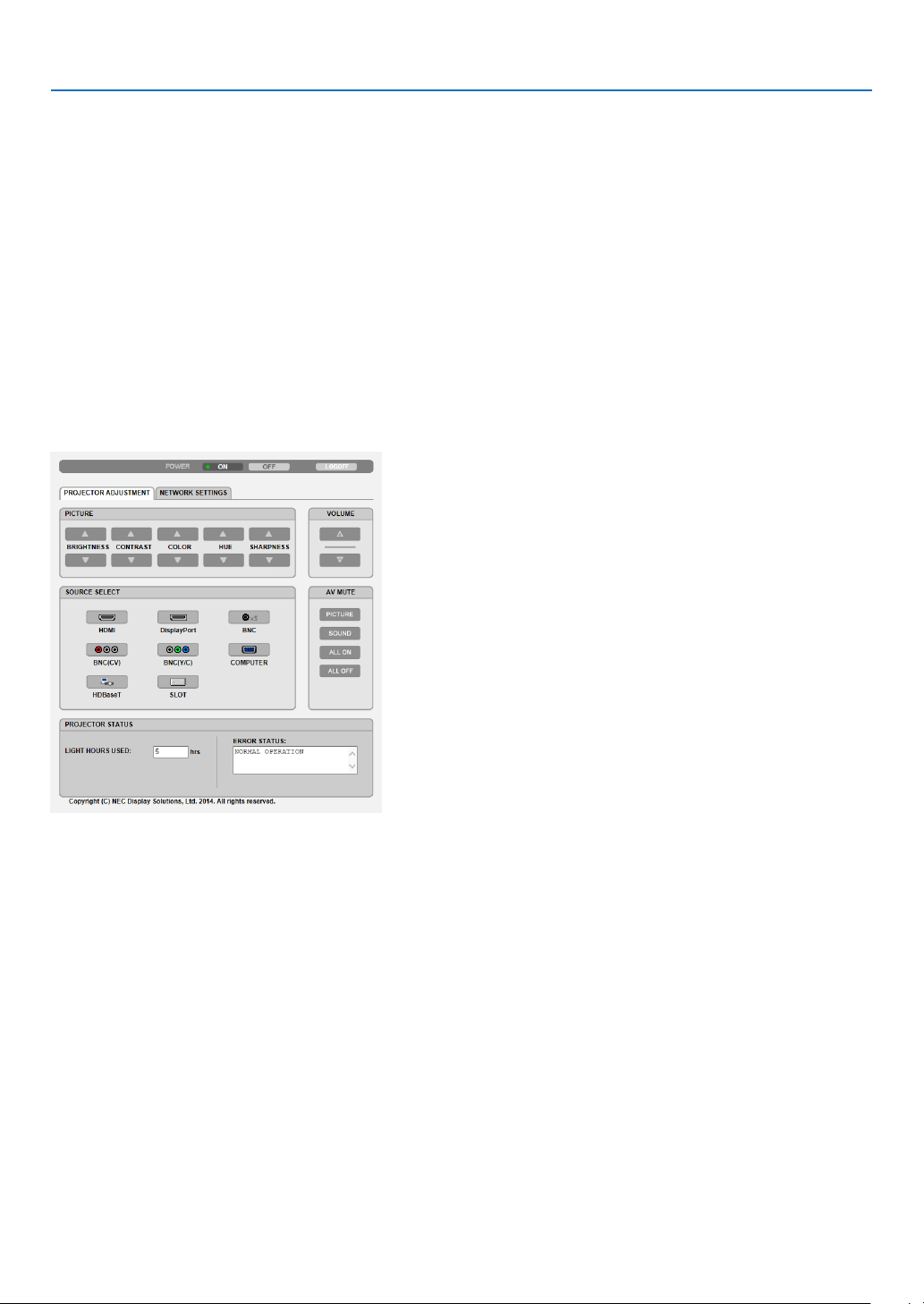
43
3. Convenient Features
Handling of the Address for Operation via a Browser
RegardingtheactualaddressthatisenteredfortheaddressorenteredtotheURLcolumnwhenoperationofthepro-
jectorisviaabrowser,thehostnamecanbeusedasitiswhenthehostnamecorrespondingtotheIPaddressofthe
projectorhasbeenregisteredtothedomainnameserverbyanetworkadministrator,orthehostnamecorresponding
totheIPaddressoftheprojectorhasbeensetinthe“HOSTS”leofthecomputerbeingused.
Example1:Whenthehostnameoftheprojectorhasbeensetto“pj.nec.co.jp”,accessisgainedtothenetwork
settingbyspecifying
http://pj.nec.co.jp/index.html
fortheaddressortheentrycolumnoftheURL.
Example2:WhentheIPaddressoftheprojectoris“192.168.73.1”,accessisgainedtothenetworksettingby
specifying
http://192.168.73.1/index.html
fortheaddressortheentrycolumnoftheURL.
PROJECTOR ADJUSTMENT
POWER:Thiscontrolsthepoweroftheprojector.
ON ������������������������� Power is switched on�
OFF ������������������������ Power is switched off�
VOLUME:Cannotbeusedforthisdevice.
AV-MUTE:Thiscontrolsthemutefunctionoftheprojector.
PICTURE ON ���������� Mutes the video�
PICTURE OFF ��������� Cancels the video muting�
SOUND ON ������������ Cannot be used for this device�
SOUND OFF ����������� Cannot be used for this device�
ALL ON ������������������ Mutes the video functions�
ALL OFF ����������������� Cancels the muting of the video functions�

44
3. Convenient Features
PICTURE:Controlsthevideoadjustmentoftheprojector.
BRIGHTNESS ▲ ���� Increases the brightness adjustment value�
BRIGHTNESS ▼ ���� Decreases the brightness adjustment value�
CONTRAST ▲ �������� Increases the contrast adjustment value�
CONTRAST ▼ �������� Decreases the contrast adjustment value�
COLOR ▲ �������������� Increases the color adjustment value�
COLOR ▼ �������������� Decreases the color adjustment value�
HUE ▲ ������������������� Increases the hue adjustment value�
HUE ▼ ������������������� Decreases the hue adjustment value�
SHARPNESS ▲ ����� Increases the sharpness adjustment value�
SHARPNESS ▼ ����� Decreases the sharpness adjustment value�
• Thefunctionsthatcanbecontrolledwillvarydependingonthesignalbeinginputtotheprojector.(→page76,
77)
SOURCESELECT:Thisswitchestheinputterminaloftheprojector.
HDMI ��������������������� Switches to the HDMI IN terminal�
DisplayPort ������������ Switches to the DisplayPort IN�
BNC ����������������������� Switch to BNC video input�
BNC(CV) ���������������� Switch to BNC (CV) video input�
BNC(Y/C) ��������������� Switch to BNC (Y/C) video input�
COMPUTER ����������� Switches to the COMPUTER 1 IN terminal�
HDBaseT ���������������� Switch to image input sent from a transmission device that supports HDBaseT�
SLOT ���������������������� The projector switches to video input from the optional board when an optional board (sold separately) is
equipped on�
PROJECTORSTATUS:Thisdisplaystheconditionoftheprojector.
LIGHT HOURS USED ����������Displays how many hours the light module has been used�
ERROR STATUS ������������������Displays the status of errors occurring within the projector�
LOGOFF:Loggingoffyourprojectorandreturningtotheauthenticationscreen(LOGONscreen).

45
3. Convenient Features
NETWORK SETTINGS
•SETTINGS
WIRED
SETTING SetforwiredLAN.
APPLY ApplyyoursettingstowiredLAN.
PROFILE1/PROFILE2 TwosettingscanbesetforwiredLANconnection.SelectPROFILE1orPROFILE2.
DISABLE TurnoffwiredLANconnection
DHCPON AutomaticallyassignIPaddress,subnetmask,andgatewaytotheprojectorfromyour
DHCPserver.
DHCPOFF SetIPaddress,subnetmask,andgatewaytotheprojectorassignedbyyournetwork
administrator.
IPADDRESS SetyourIPaddressofthenetworkconnectedtotheprojector.
SUBNETMASK Setyoursubnetmasknumberofthenetworkconnectedtotheprojector.
GATEWAY Setthedefaultgatewayofthenetworkconnectedtotheprojector.
AUTODNSON DHCPserverwill automaticallyassign IP addressof DNS serverconnectedto the
projector.
AUTODNSOFF SetyourIPaddressofDNSserverconnectedtotheprojector.

46
3. Convenient Features
•NAME
PROJECTORNAME Enteraname foryourprojector sothatyourcomputer canidentify theprojector. A
projectornamemustbe16charactersorless.
TIP:Projectornamewillnotbeaffectedevenwhen[RESET]isdonefromthemenu.
HOSTNAME Enterthehostnameofthenetworkconnectedtotheprojector.Ahostnamemustbe
15orless.
DOMAINNAME Enterthedomainnameofthe networkconnectedtotheprojector.Adomainname
mustbe60charactersorless.
•ALERTMAIL
ALERTMAIL Thisoptionwillnotifyyourcomputeroferrormessagesviae-mailwhenusingwiredLAN.
PlacingacheckmarkwillturnontheAlertMailfeature.
ClearingacheckmarkwillturnofftheAlertMailfeature.
Sampleofamessagetobesentfromtheprojector:
Subject:[Projector]ProjectorInformation
THECOOLINGFANHASSTOPPED.
[INFORMATION]
PROJECTORNAME:PX602ULSeries
LIGHTHOURSUSED:0000[H]
SENDER’SADDRESS Entersender’saddress.
SMTPSERVERNAME EntertheSMTPservernametobeconnectedtotheprojector.
RECIPIENT’SADDRESS
1,2,3
Enteryourrecipient’saddress.Uptothreeaddressescanbeentered.
TESTMAIL Sendatestmailtocheckwhetheryoursettingsarecorrectornot
NOTE:
• Ifyouexecuteatest,youmaynotreceiveanAlertmail.Shouldthishappen,checkifnetwork
settings are correct.
• Ifyouenteredanincorrectaddressinatest,youmaynotreceiveanAlertmail.Shouldthis
happen,checkiftheRecipient’sAddressiscorrect.
SAVE Clickthisbuttontosaveyoursettingstotheprojector’smemory.

47
3. Convenient Features
•NETWORKSERVICE
PJLinkPASSWORD SetapasswordforPJLink*.Apasswordmustbe32charactersorless.Donotforget
yourpassword.However,ifyouforgetyourpassword,consultwithyourdealer.
HTTPPASSWORD SetapasswordforHTTPserver.Apasswordmustbe10charactersorless.
Whenapasswordissetup,youwillbepromptedforyourusername(arbitrary)and
passwordduringLOGON.
AMXBEACON TurnonorofffordetectionfromAMXDeviceDiscoverywhenconnectingtothenetwork
supportedbyAMX’sNetLinxcontrolsystem.
TIP:
WhenusingadevicethatsupportsAMXDeviceDiscovery,allAMXNetLinxcontrolsystemwill
recognizethedeviceanddownloadtheappropriateDeviceDiscoveryModulefromanAMXserver.
PlacingacheckmarkwillenabledetectingtheprojectorfromAMXDeviceDiscovery.
ClearingacheckmarkwilldisabledetectingtheprojectorfromAMXDeviceDiscovery.
NOTE:Ifyouforgetyourpassword,contactyourdealer.
*WhatisPJLink?
PJLinkisastandardizationofprotocolusedforcontrollingprojectorsofdifferentmanufacturers.Thisstandard
protocolisestablishedbyJapanBusinessMachineandInformationSystemIndustriesAssociation(JBMIA)in2005.
TheprojectorsupportsallthecommandsofPJLinkClass1.
SettingofPJLinkwillnotbeaffectedevenwhen[RESET]isdonefromthemenu.
CRESTRON
•ROOMVIEWformanagingfromthecomputer.
DISABLE DisablesROOMVIEW.
ENABLE EnablesROOMVIEW.
•CRESTRONCONTROLformanagingfromthecontroller.
DISABLE DisablesCRESTRONCONTROL.
ENABLE EnablesCRESTRONCONTROL.
IPADDRESS SetyourIPaddressofCRESTRONSERVER.
IPID SetyourIPIDofCRESTRONSERVER.
•INFORMATION
WIREDLAN DisplayalistofsettingsofwiredLANconnection.
UPDATE Reectsettingswhentheyarechanged.
TIP:TheCRESTRONsettingsarerequiredonlyforusewithCRESTRONROOMVIEW.
Formoreinformation,visithttp://www.crestron.com
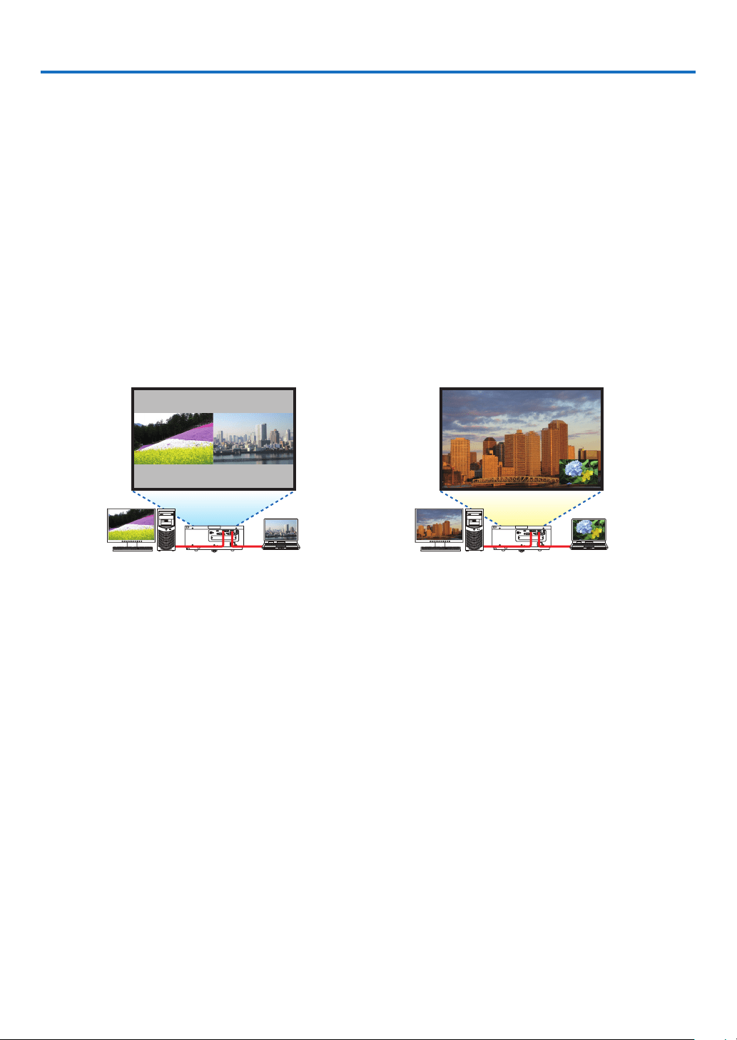
48
4. Multi-Screen Projection
❶ Things that can be done using multi-screen projection
Thisprojectorcanbeusedsinglyorarrangedinmultipleunitsformulti-screenprojection.
Wewillintroduceanexampleusingtwoprojectionscreenshere.
Case 1
Usingasingleprojectortoprojecttwotypesofvideosatthesametime
[PIP/PICTUREBYPICTURE]
Case 2
Usingfourprojectors(resolution:WUXGA)toprojectvideowitharesolutionof2560×1600pixels
[TILING]
Case 1. Using a single projector to project two types of videos [PIP/PICTURE BY
PICTURE]
Connection example and projection image
Inthecaseof[PICTUREBYPICTURE] Inthecaseof[PIP]
On-screenmenuoperations
Display[DISPLAY]→[PIP/PICTUREBYPICTURE]→[MODE]screenintheon-screenmenuandselect[PIP]or
[PICTUREBYPICTURE].
Fordetails,pleasereferto“4-2DisplayingTwoPicturesattheSameTime”.(→page52)
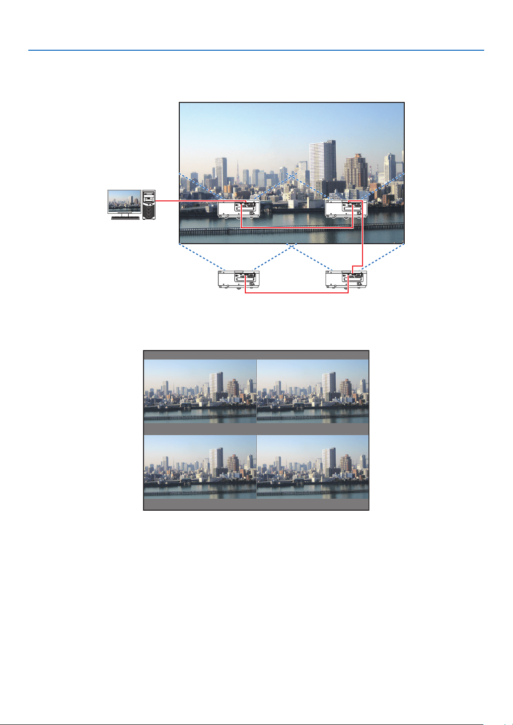
4. Multi-Screen Projection
49
Case 2. Using four projectors (resolution: WUXGA) to project videos with a resolution of
2560 × 1600 pixels [TILING]
Connection example and projection image
On-screenmenuoperations
1 Foursimilarvideosaredisplayedwhenfourprojectorsareprojected.
Pleaserequestthedealertoadjusttheprojectionpositionofeachprojector.
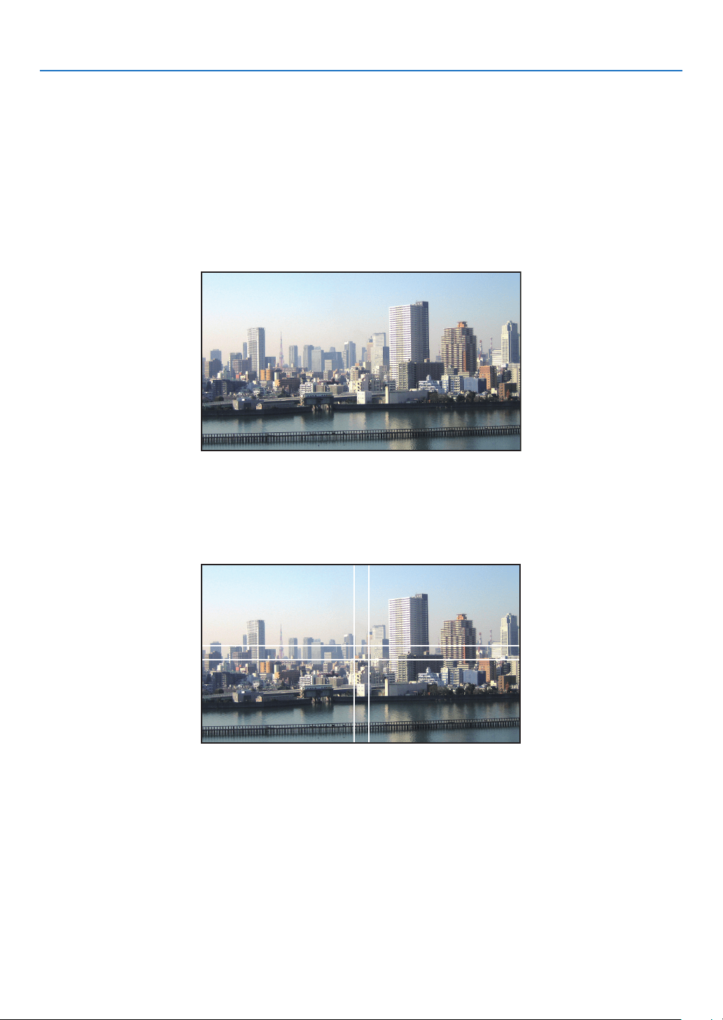
4. Multi-Screen Projection
50
2 Operatetheon-screenmenuusingthefourrespectiveprojectorstodividetheimageintofourportions.
Display[DISPLAY]→[MULTISCREEN]→[PICTURESETTING]Screenintheon-screenmenuandselect[TIL-
ING].
(1)Inthescreenforsettingthenumberofhorizontalunits,select[2UNITS].(numberofunitsinthehorizontaldirec-
tion)
(2)Inthescreenforsettingthenumberofverticalunits,select[2UNITS].(numberofunitsintheverticaldirection)
(3)Inthescreenforsettingthehorizontalorder,select[1stUNIT]or[2ndUNIT].
(lookatthescreens,theoneontheleftisthe[1stUNIT]whiletheoneontherightisthe[2ndUNIT])
(4)Inthescreenforsettingtheverticalorder,selectthe[1stUNIT]orthe[2ndUNIT].
(lookatthescreens,theoneatthetopisthe[1stUNIT]whiletheoneatthebottomisthe[2ndUNIT])
3 Adjustthelensshiftofeachprojectortone-tunetheboundariesofthescreen.
Forfurtherne-tuning,adjustusing[DISPLAY]→[EDGEBLENDING]intheon-screenmenuforeachprojector.
Fordetails,pleasereferto“4-3DisplayingaPictureUsing[EDGEBLENDING]”.
(→page56)
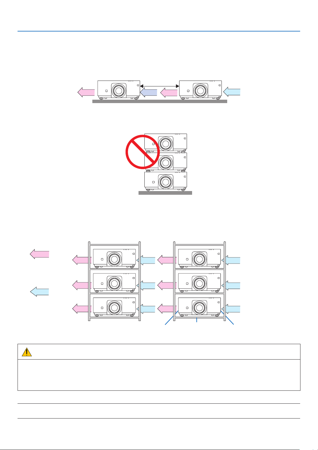
4. Multi-Screen Projection
51
Things to note when installing projectors
• Leave1moroverspacebetweentheprojectorswhenprojectorsareinstalledsidebyside,sothattheintakeand
exhaustventsoftheprojectorsarenotobstructed.Inaddition,leaveaspaceofatleast30cmbetweentheintake/
exhaustventand thewall.Whenthe airintakeand dischargeoutletareobstructed,thetemperatureinsidethe
projectorwillriseandthismayresultinamalfunction.
1morgreater
• Twoprojectorscanbestackedontopofeachother(STACKsetting).(→page138)Donotattempttodirectlystack
threeormoreprojectors.Whentheprojectorsarepiledupontopofoneanother,theymayfalldown,resultingin
damageandfailure.
• Installationexamplewhenusing3ormoreprojectors
Thefollowinginstallationisrecommendedwheninstallingacombinationof3ormoreprojectorsformulti-screen
projection.
[Installationexample]
IntakeventExhaustvent Cabinet
Airdischarge
Airintake
Front Front
WARNING
Pleaserequestthedealerforspecialinstallationservicessuchaswhenmountingtheprojectortotheceiling.Never
carryouttheinstallationbyyourself.Theprojectormayfalldownandresultininjury.Pleaseuseasturdycabinet
thatcanwithstandtheweightoftheprojectorfortheinstallation.Pleasedonotpileuptheprojectorsdirectlyon
topofoneanother.
NOTE:
• Fortherangeoftheprojectiondistance,pleaserefertotheAppendix“Throwdistanceandscreensize”.(→ page 153)
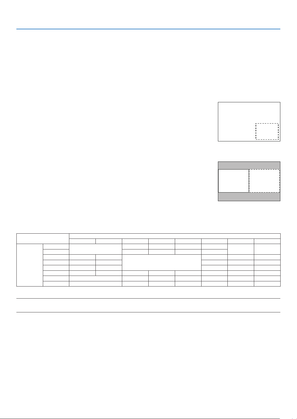
4. Multi-Screen Projection
52
❷ Displaying Two Pictures at the Same Time
Theprojectorhasafeaturethatallowsyoutoviewtwodifferentsignalssimultaneously.Youhavetwomodes:picture
inpicture(PIP)modeandpicturebypicture(PICTUREBYPICTURE)mode.
Theprojectionvideointherstscreendisplayisknownasthemaindisplaywhiletheprojectionvideothatiscalled
outsubsequentlyisknownasthesub-display.
Selecttheprojectionfunctionunder[DISPLAY]→[PIP/PICTUREBYPICTURE]→[MODE]intheon-screenmenu
(thedefaultfactorysettingwhenshippedisPIP).(→page85)
• Asinglescreenisprojectedwhenpoweristurnedon.
PictureinPicturefunction(PIP)
Asmallsub-displayisdisplayedinsidethemaindisplay.
Thesub-displaycanbesetupandadjustedasfollows.(→page86)
• Selectwhethertodisplaythesub-displayatthetopright,topleft,bottomright
orbottomleftofthescreen(thesizeofthesub-displaycanbeselectedand
thepositioncanbene-tuned)
• Switchthemaindisplaywiththesub-display
Main Display
Sub-Display
Picturebypicturefunction(PICTUREBYPICTURE)
Displaythemaindisplayandsub-displaysidebyside.
Themaindisplayandsub-displaycanbesetupandadjustedasfollows.(→
page86)
• Selectingthedisplayboundary(ratio)ofthemaindisplayandsub-display
• Switchthemaindisplayandsub-display
Main Display Sub-Display
Inputterminalsthatcanbeusedforthemainscreenandsub-screen.
Themainscreenandsub-screencanprovidethefollowinginputterminals.
• Themaindisplayandsub-displaysupportcomputersignalsuptoWUXGA@60HzRB.
Sub-Display or additional display
HDMI DisplayPort BNC BNC(CV) BNC(Y/C) COMPUTER HDBaseT SLOT
Main Display
HDMI
No
Yes Yes Yes Yes
No No
DisplayPort Yes Yes Yes Yes
BNC Yes Yes
No
No Yes Yes
BNC(CV) Yes Yes Yes Yes Yes
BNC(Y/C) Yes Yes Yes Yes Yes
COMPUTER Yes Yes No Yes Yes No Yes Yes
HDBaseT No Yes Yes Yes Yes No No
SLOT No Yes Yes Yes Yes No No
NOTE:
• Somesignalsmaynotappeardependingontheresolution.
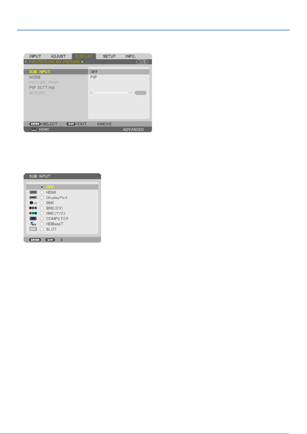
4. Multi-Screen Projection
53
Projecting two screens
1. PresstheMENUbuttontodisplaytheon-screenmenuandselect[DISPLAY]→[PIP/PICTUREBYPICTURE].
Thisdisplaysthe[PIP/PICTUREBYPICTURE]screenintheon-screenmenu.
2. Select[SUBINPUT]usingthe▼/▲ buttons, and press the ENTER button.
Thisdisplaysthe[SUBINPUT]screen.
3. Select the input signal using the ▼/▲ buttons, and press the ENTER button.
The[PIP](PICTUREINPICTURE)or[PICTUREBYPICTURE]screensetupunder[MODE]isprojected.(→page
85)
• Whenthesignalnameisdisplayedingrey,thismeansthatitcannotbeselected.
• ThesignalcanalsobeselectedbypressingthePIP/FREEZEbuttonontheremotecontrol.
4. Press the MENU button.
Theon-screenmenuwilldisappear.
5. Whenreturningtosinglescreen,displaythe[PIP/PICTUREBYPICTUE]screenonemoretimeandselect
[OFF]inthe[SUBINPUT]screenoftheStep3.
TIP:
• Duringdual-screenprojection,iftheselectedinputisnotsupportedbythesub-screen,thesub-screenwillappearasablack
screen.
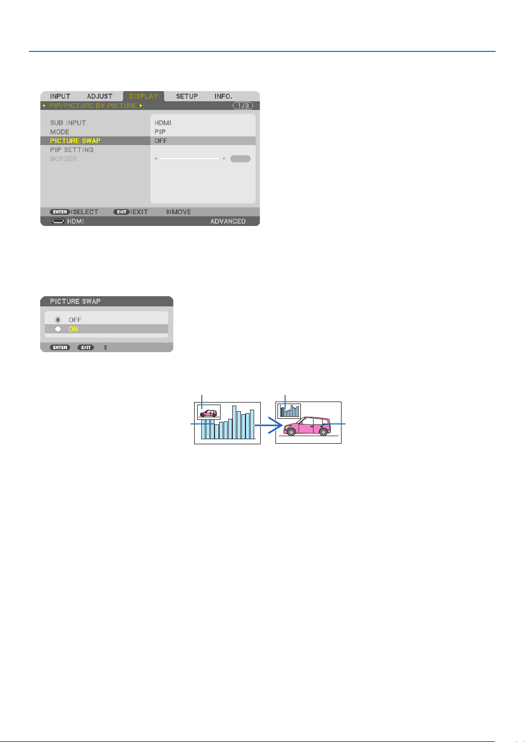
4. Multi-Screen Projection
54
Switching the main display with the sub-display and vice versa
1. PresstheMENUbuttontodisplaytheon-screenmenuandselect[DISPLAY]→[PIP/PICTUREBYPICTURE].
Thisdisplaysthe[PIP/PICTUREBYPICTURE]screenintheon-screenmenu.
2. Select[PICTURESWAP]usingthe▼/▲ buttons and then press the ENTER button.
Displaythescreenforswitchingthedisplaypositions.
3. Select[ON]usingthe▼ button and then press the ENTER button.
Thevideoofthemaindisplaywillswitchwiththatofthesub-display.
Whenturned“OFF” Whenturned“ON”
Sub-displayvideo
Maindisplayvideo Sub-displayvideo
Maindisplayvideo
ThesignaloutputfromtheHDMIOUTterminaldoesnotchangeevenifthedisplaypositionsareswitched.
4. Press the menu button.
Theon-screenmenuwilldisappear.

4. Multi-Screen Projection
55
Restrictions
• Thefollowingoperationsareenabledonlyforthemaindisplay.
• Visualadjustments
• Videomagnication/demaginicationusingthepartialD-ZOOM/ZOOM+/−buttons.
However,magnication/demaginicationisuptotheboundarysetin[PICTUREBYPICTURE].
• TESTPATTERN
• Thefollowingoperationsareenabledforboththemaindisplayandsub-display.Theseoperationscannotbeap-
pliedindividually.
• Momentarydeletionofvideo
• Videopause
• [PIP/PICTUREBYPICTURE]cannotbeusedwhena3Dvideoisbeingdisplayed.
• Whenusingthe[PIP/PICTUREBYPICTURE]function,[CLOSEDCAPTION]and[DYNAMICCONTRAST]can
beused.
• [PIP/PICTUREBYPICTURE]cannotbeusedwhenthesignalinputhasaresolutionof1920×1200ormore.
• TheHDMIOUTterminalhasarepeaterfunction.Theoutputresolutionislimitedbythemaximumresolutionof
theconnectedmonitorandprojector.
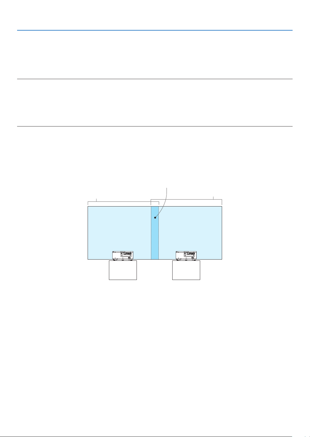
4. Multi-Screen Projection
56
❸ Displaying a Picture Using [EDGE BLENDING]
Ahighresolutionvideocanbeprojectedonanevenbiggerscreenbycombiningmultipleprojectorsontheleft,right,
topandbottom.
Thisprojectorisequippedwithan“EDGEBLENDINGFunction”thatmakestheedges(boundaries)oftheprojection
screenindistinguishable.
NOTE:
• Forprojectorthrowdistances,referto“Throwdistanceandscreensize”onpage153.
• BeforeperformingtheEdgeBlendingfunction,placetheprojectorinthecorrectpositionsothattheimagebecomessquarein
theappropriatesize,andthenmakeopticaladjustments(lensshift,focus,andzoom).
• Adjustthebrightnessofeachprojectorusing[ADJUST]under[LIGHTMODE].Afteradjustingthebrightness,youcankeepthe
setbrightnesslevelbyturningONthe[CONSTANTBRIGHTNESS]mode.Inaddition,use[REF.WHITEBALANCE]toadjustthe
[CONTRAST]and[BRIGHTNESS].
BeforeexplaininguseoftheEdgeBlendingfunction
Thissectionexplainsthecasefor“Example:Placingtwoprojectorssidebyside”.Asshown,theprojectedimageon
theleftisreferredtoas“ProjectorA”andtheprojectedimageontherightisreferredto“ProjectorB”.Unlessotherwise
speciedhereinafter,the“projector”isusedtomeanbothAandB.
Example:Placingtwoprojectorssidebyside
EdgeBlendingarea
Projectedarea
Projectedarea
ProjectorA ProjectorB
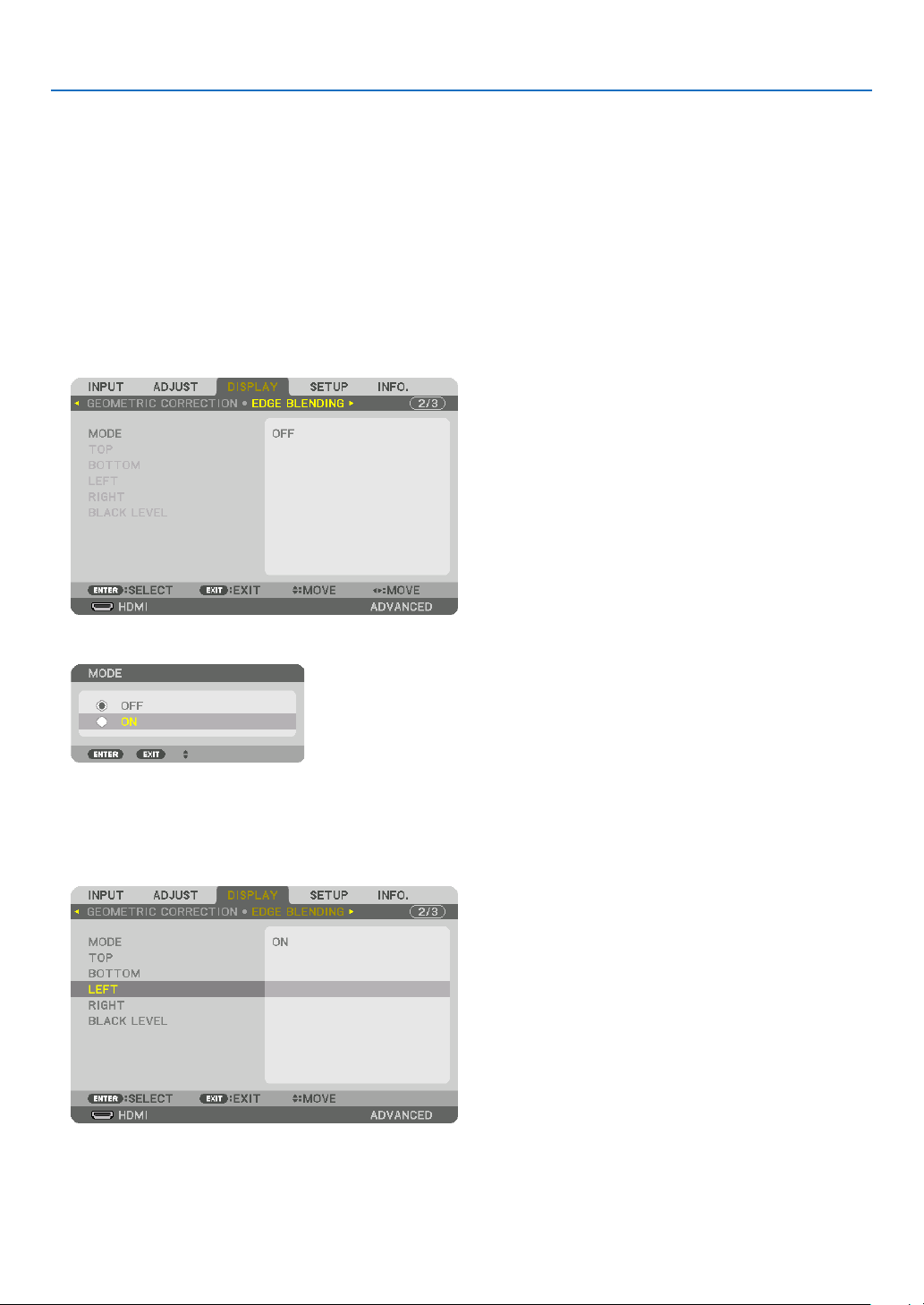
4. Multi-Screen Projection
57
Preparation:
• Turnontheprojectoranddisplayasignal.
• Whenperformingsettingsoradjustmentsusingtheremotecontrol,enablethe[CONTROLID]soasnottoactivate
theotherprojectors.(→page105)
Setting the overlap of projection screens
①
Enable[EDGEBLENDING].
1. Press the MENU button.
Themenuwillbedisplayed.
2. Select[EDGEBLENDING].
The[EDGEBLENDING]screenwillbedisplayed.Alignthecursorwith[MODE]andthenpresstheENTERbutton.
Themodescreenwillbedisplayed.
3. Select[MODE]→[ON]andpresstheENTERbutton.
ThisenablestheEdgeBlendingfunction.Thefollowingmenuitemsareavailable:
[TOP],[BOTTOM],[LEFT],[RIGHT],and[BLACKLEVEL]
4. Select[RIGHT]forProjectorAand[LEFT]forProjectorB.
PresstheENTERbutton.
Thefollowingitemsareavailable:
[CONTROL],[MARKER],[RANGE],and[POSITION]
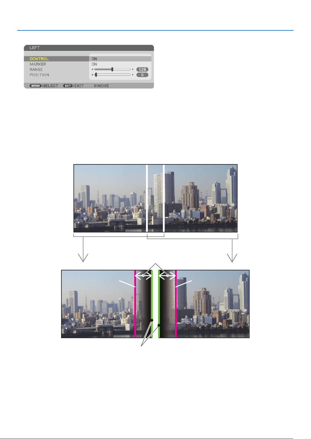
4. Multi-Screen Projection
58
5. Select[CONTROL]→[ON]andpresstheENTERbutton.
Each[TOP],[BOTTOM],[LEFT],[RIGHT],and[BLACKLEVEL]hasitsown[CONTROL],[MARKER],[RANGE],
and[POSITION].
• ForProjectorA,setthe[CONTROL]forthe[TOP],[LEFT]and[BOTTOM]to[OFF].SimilarlyforProjectorB,set
the[CONTROL]forthe[TOP],[RIGHT]and[BOTTOM]to[OFF].
②Adjust[RANGE]and[POSITION]todetermineanareaofoverlappededgesofimages
projected from each projector.
Turningon[MARKER]willdisplaymarkersinmagentaandgreen.
Themagentamarkerisusedfor[RANGE]andgreenonefor[POSITION].
[RANGE]
(Determineanareaofoverlappededgesof
images.)
[POSITION]
(Determinethepositionofoverlappededgesofimages.)
Greenmarker
Turnon[RIGHT]
Magentamarker
Turnon[LEFT]
Magentamarker
* The2screensareseparatedinthediagramforexplanatorypurposes.
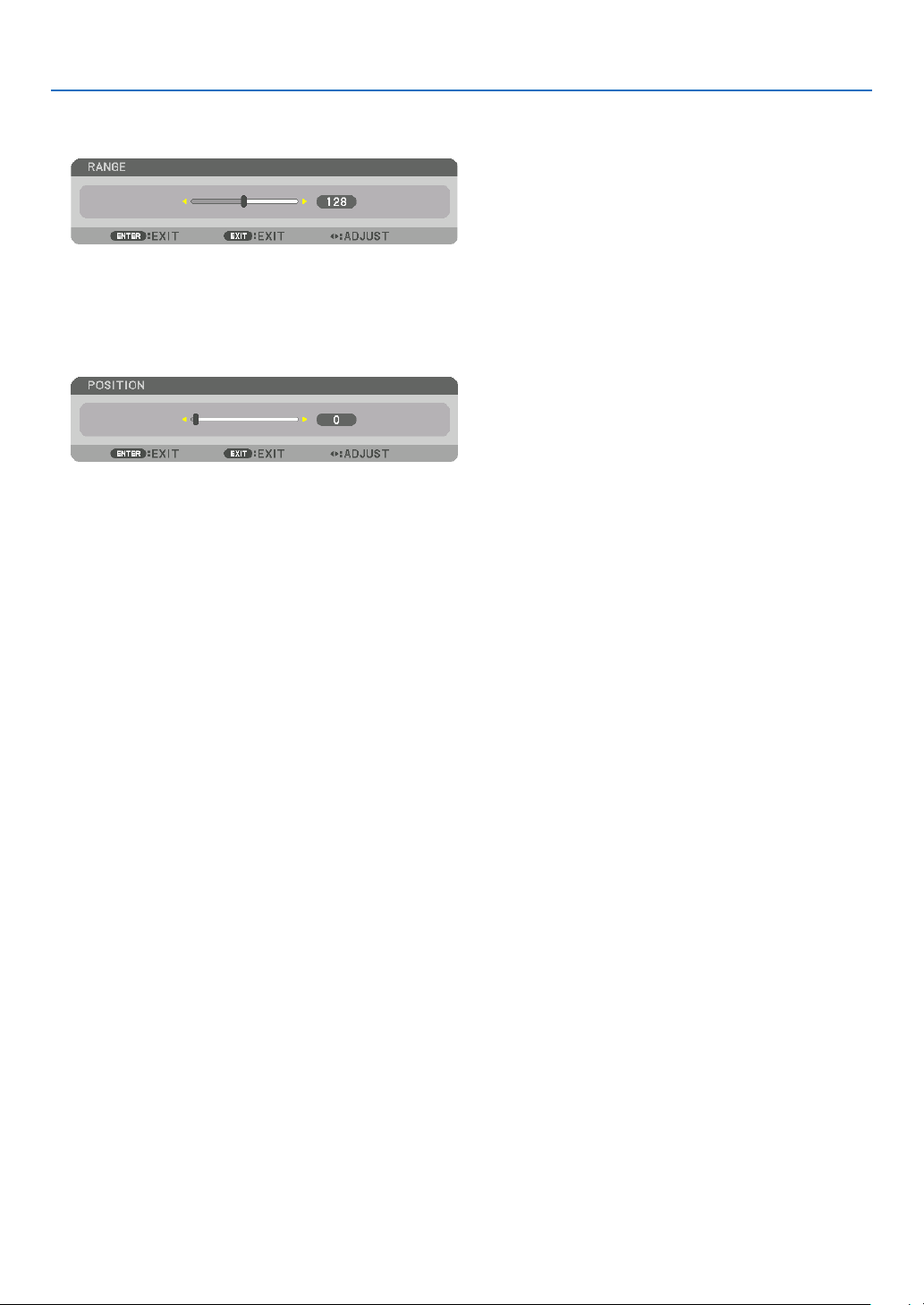
4. Multi-Screen Projection
59
1 Adjust[RANGE].
Usethe◀or▶buttontoadjusttheoverlappedarea.
TIP:
• Adjusttooverlaponeprojector’markerwiththeotherprojector’smarker.
2 Adjust[POSITION].
Usethe◀or▶buttontoalignoneedgewiththeotheredgeofoverlappedimages.
TIP:
• Whendisplayingasignalwithadifferentresolution,performtheEdgeBlendingfunctionfromthestart.
• Settingof[MARKER]willnotbesavedandreturnto[OFF]whentheprojectoristurnedoff.
• Todisplayorhidethemarkerwhiletheprojectorisrunning,turnonoroff[MARKER]fromthemenu.
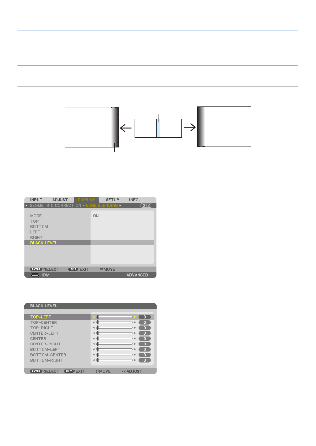
4. Multi-Screen Projection
60
Black Level Adjustment
Thisadjuststheblackleveloftheoverlappingareaandthenon-overlappingareaofthemulti-screen(EDGEBLENDING).
Adjustthebrightnesslevelifyoufeelthedifferenceistoolarge.
NOTE:
Thisfunctionisenabledonlywhen[MODE]isturnedon.
Adjustableareavariesdependingonwhatcombinationof[TOP],[BOTTOM],[LEFT]and[RIGHT]areturnedon.
Example:AdjustingtheBlackLevelwhenplacingtwoprojectorssidebyside
Widthofoverlap
Adjust[CENTER] Adjust[CENTER]
ProjectorA’s
image
ProjectorB’s
image
Adjust[CENTER-RIGHT] Adjust[CENTER-LEFT]
1. Turnon[MODE]
2. Select[BLACKLEVEL]andpresstheENTERbutton.
Thescreenwillswitchtotheblackleveladjustmentscreen.
3. Use the ▼ or ▲ button to select an item and use the ◀ or ▶ to adjust the black level.
Dothisfortheotherprojectorifnecessary.
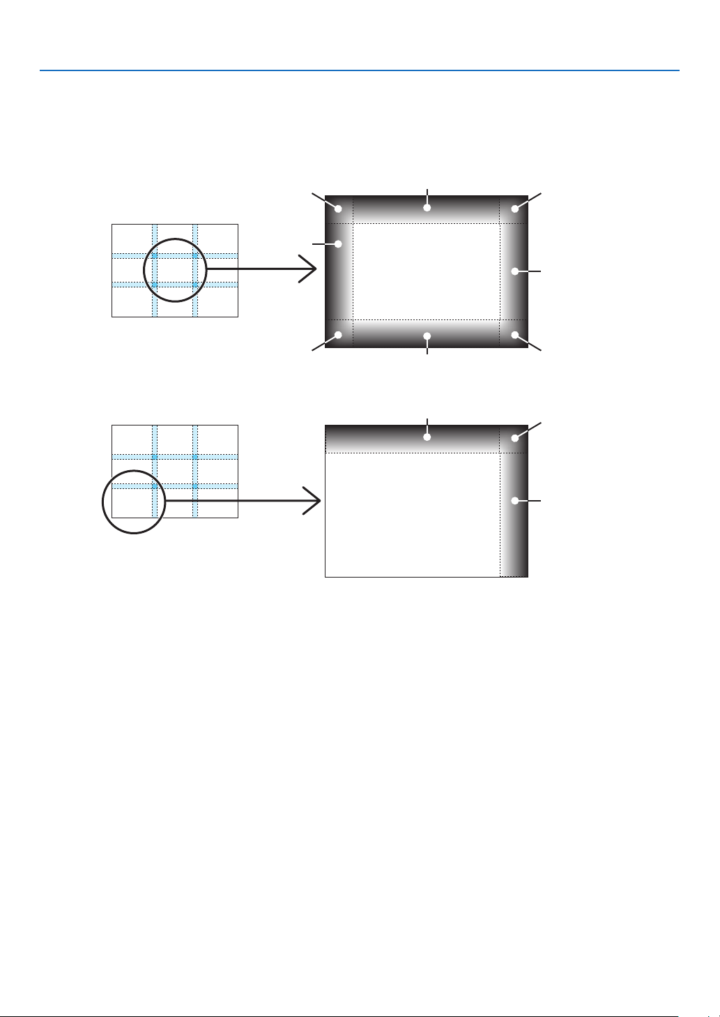
4. Multi-Screen Projection
61
9-segmentedportionsforBlackLeveladjustment
Thecenterprojector
Thisfunctionadjuststhebrightnesslevelof9-segmentedportionsforthecenterprojectorand4-segmentedportions
fortheleftbottomprojectorasshownbelow.
TOP-LEFT
BOTTOM-LEFT
CENTER-
LEFT
TOP-RIGHT
CENTER-RIGHT
BOTTOM-RIGHT
TOP-CENTER
CENTER
CENTER
BOTTOM-CENTER
TOP-RIGHT
CENTER-RIGHT
TOP-CENTER
TIP:
• Thenumberofblackleveldivisionscreens(maximumofninedivisions)changesdependingonthenumberofedgeblending
positionsselected(top,bottom,right,left).Inaddition,whenthetop/bottomandleft/rightendsareselected,thecornerdivision
screen appears.
• Theedgeblendingwidthisthewidthsetintherangeandthecornerisformedbytheintersectingareaofthetop/bottomends
orleft/rightends.
• The[BLACKLEVEL]canbeadjustedtomakeitbrighteronly.
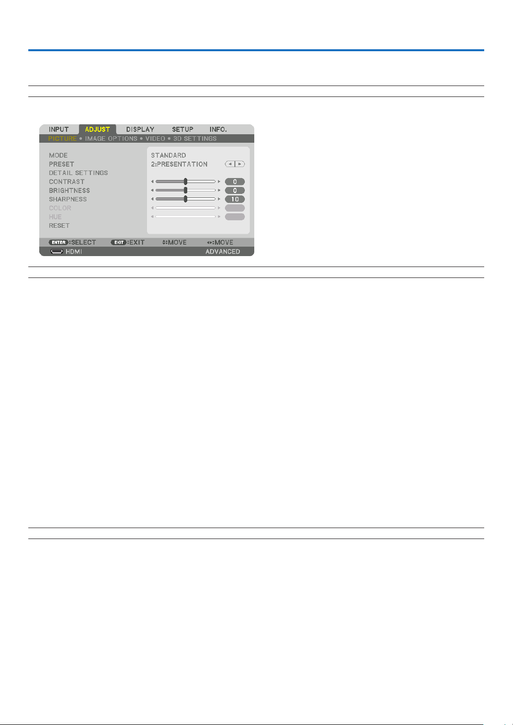
62
5. Using On-Screen Menu
❶ Using the Menus
NOTE: The on-screen menu may not be displayed correctly depending on input signal and the projector setting.
1. Press the MENU button on the remote control or the projector cabinet to display the menu.
NOTE: The commands such as ENTER,EXIT,▲▼, ◀▶ in the bottom show available buttons for your operation.
2. Press the ◀▶ buttons on the remote control or the projector cabinet to display the submenu.
3. PresstheENTERbuttonontheremotecontrolortheprojectorcabinettohighlightthetopitemortherst
tab.
4. Use the ▲▼ buttons on the remote control or the projector cabinet to select the item you want to adjust or
set.
You can use the ◀▶ buttons on the remote control or the projector cabinet to select the tab you want.
5. Press the ENTER button on the remote control or the projector cabinet to display the submenu window.
6. Adjustthelevelorturntheselecteditemonoroffbyusingthe▲▼◀▶ buttons on the remote control or
the projector cabinet.
Changesarestoreduntiladjustedagain.
7. Repeat steps 2-6 to adjust an additional item, or press the EXIT button on the remote control or the projec-
tor cabinet to quit the menu display.
NOTE:Whenamenuormessageisdisplayed,severallinesofinformationmaybelost,dependingonthesignalorsettings.
8. Press the MENU button to close the menu.
To return to the previous menu, press the EXIT button.
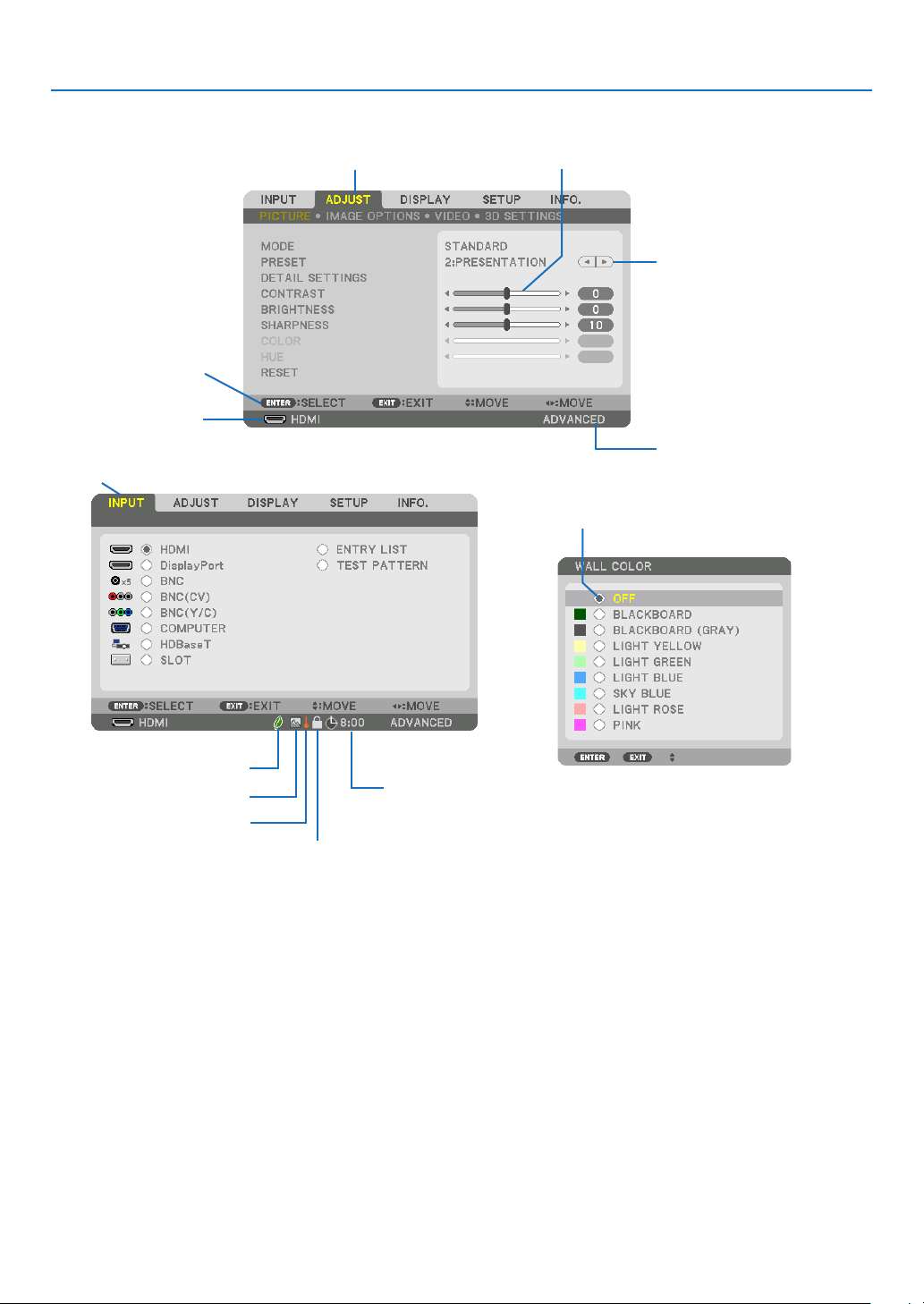
63
5. Using On-Screen Menu
❷
Menu Elements
Slidebar
Solidtriangle
Menumode
Tab
Radiobutton
HIGHsymbol
LIGHTMODEsymbol
Menuwindowsordialogboxestypicallyhavethefollowingelements:
Highlight ����������������������������� Indicates the selected menu or item�
Solid triangle ����������������������Indicates further choices are available� A highlighted triangle indicates the item is active�
Tab ��������������������������������������Indicates a group of features in a dialog box� Selecting on any tab brings its page to the front�
Radio button ����������������������� Use this round button to select an option in a dialog box�
Source ��������������������������������Indicates the currently selected source�
Menu mode ������������������������Indicates the current menu mode: BASIC or ADVANCED�
Off Timer remaining time ���� Indicates the remaining countdown time when the [OFF TIMER] is preset�
Slide bar �����������������������������Indicates settings or the direction of adjustment�
LIGHT MODE symbol ����������Indicates [LIGHT MODE] is set�
Key Lock symbol ����������������Indicates the [CONTROL PANEL LOCK] is enabled�
Thermometer symbol ���������Indicates the [LIGHT MODE] is forcibly set to [ECO] mode because the internal temperature is too
high�
HIGH symbol ����������������������Indicates the [FAN MODE] is set to [HIGH] mode�
Source
Availablebuttons
Thermometersymbol
KeyLocksymbol
OffTimerremaining
time
Highlight
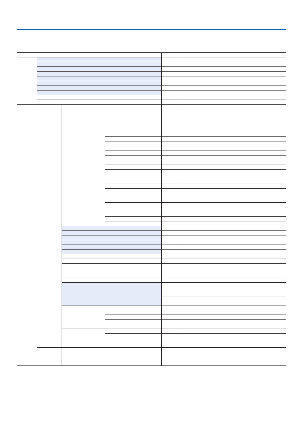
64
5. Using On-Screen Menu
* Theasterisk(*)indicatesthatthedefaultsettingvariesdependingonthesignal.
*1 The[GAMMACORRECTION]itemisavailablewhenanitemotherthan[DICOMSIM.]isselectedfor[REFERENCE].
*2 The[SCREENSIZE]itemisavailablewhen[DICOMSIM.]isselectedfor[REFERENCE].
*3 When[PRESENTATION]or[HIGH-BRIGHT]isselectedin[REFERENCE],the[COLORTEMPERATURE]isnotavailable.
•Basicmenuitemsareindicatedbyshadedarea.
❸ List of Menu Items
Somemenuitemsarenotavailabledependingontheinputsource.
Menu Item Default Options
INPUT
HDMI *
DisplayPort *
BNC *
BNC(CV) *
BNC(Y/C) *
COMPUTER *
HDBaseT
SLOT
ENTRY LIST
TEST PATTERN
ADJUST
PICTURE
MODE STANDARD STANDARD, PROFESSIONAL
PRESET *
HIGH-BRIGHT, PRESENTATION, VIDEO, MOVIE, GRAPHIC, sRGB,
DICOM SIM�
DETAIL SETTINGS
GENERAL
REFERENCE *
HIGH-BRIGHT, PRESENTATION, VIDEO, MOVIE, GRAPHIC, sRGB,
DICOM SIM�
GAMMA CORRECTION*
1
DYNAMIC, NATURAL, BLACK DETAIL
SCREEN SIZE*
2
* LARGE, MEDIUM, SMALL
COLOR TEMPERATURE*
3
*
DYNAMIC CONTRAST * OFF, ON
Brilliant Color * OFF, MEDIUM, HIGH
IMAGE MODE * STILL, MOVIE
WHITE BALANCE
CONTRAST R 0
CONTRAST G 0
CONTRAST B 0
BRIGHTNESS R 0
BRIGHTNESS G 0
BRIGHTNESS B 0
COLOR CORRECTION
RED 0
GREEN 0
BLUE 0
YELLOW 0
MAGENTA 0
CYAN 0
CONTRAST 50
BRIGHTNESS 50
SHARPNESS 10
COLOR 50
HUE 0
RESET
IMAGE
OPTIONS
CLOCK *
PHASE *
HORIZONTAL *
VERTICAL *
BLANKING * TOP, BOTTOM, LEFT, RIGHT
OVERSCAN AUTO AUTO, 0[%], 5[%], 10[%]
ASPECT RATIO
AUTO (COMPUTER) AUTO, 4:3, 5:4, 16:9, 15:9, 16:10, NATIVE
AUTO
(COMPONENT/VIDEO/S-VIDEO) AUTO, 4:3, LETTERBOX, WIDE
SCREEN, ZOOM
AUTO
(COMPONENT/VIDEO/S-VIDEO) AUTO, 4:3 WINDOW, LETTERBOX,
WIDE SCREEN, FULL
INPUT RESOLUTION * –
VIDEO
NOISE REDUCTION
RANDOM NR OFF OFF, LOW, MEDIUM, HIGH
MOSQUITO NR OFF OFF, LOW, MEDIUM, HIGH
BLOCK NR OFF OFF, LOW
DEINTERLACE NORMAL NORMAL, MOVIE, STILL
CONTRAST
ENHANCEMENT
MODE AUTO OFF, AUTO, NORMAL
GAIN
SIGNAL TYPE AUTO AUTO, RGB, COMPONENT
VIDEO LEVEL AUTO AUTO, NORMAL, ENHANCED, SUPER WHITE
3D SETTINGS
FORMAT AUTO
AUTO, OFF(2D), FRAME PACKING, SIDE BY SIDE(HALF), SIDE
BY SIDE(FULL), TOP AND BOTTOM, FRAME ALTERNATIVE, LINE
ALTERNATIVE
L/R INVERT OFF OFF, ON

65
5. Using On-Screen Menu
Menu Item Default Options
DISPLAY
PIP/PICTURE
BY PICTURE
SUB INPUT
OFF, HDMI, DisplayPort, BNC, BNC(CV), BNC(Y/C), COMPUTER,
HDBaseT, SLOT
MODE PIP PIP, PICTURE BY PICTURE
PICTURE SWAP OFF OFF, ON
PIP SETTING
START POSITION TOP-LEFT TOP-LEFT, TOP-RIGHT, BOTTOM-LEFT, BOTTOM-RIGHT
HORIZONTAL POSITION
VERTICAL POSITION
SIZE MEDIUM LARGE, MEDIUM, SMALL
BORDER
GEOMETRIC
CORRECTION
KEYSTONE
HORIZONTAL
VERTICAL
TILT
THROW RATIO
CORNERSTONE
TOP-LEFT, TOP-CENTER, TOP-RIGHT, CENTER-LEFT, CENTER-
RIGHT, BOTTOM-LEFT, BOTTOM-CENTER, BOTTOM-RIGHT
HORIZONTAL CORNER
TOP-LEFT, TOP-CENTER, TOP-RIGHT, CENTER-LEFT, CENTER-
RIGHT, BOTTOM-LEFT, BOTTOM-CENTER, BOTTOM-RIGHT
VERTICAL CORNER
TOP-LEFT, TOP-CENTER, TOP-RIGHT, CENTER-LEFT, CENTER-
RIGHT, BOTTOM-LEFT, BOTTOM-CENTER, BOTTOM-RIGHT
PINCUSHION TOP, BOTTOM, LEFT, RIGHT
PC TOOL OFF OFF, 1, 2, 3
RESET
EDGE
BLENDING
MODE OFF OFF, ON
TOP
CONTROL ON OFF, ON
MARKER ON OFF, ON
RANGE
POSITION
BOTTOM
CONTROL ON OFF, ON
MARKER ON OFF, ON
RANGE
POSITION
LEFT
CONTROL ON OFF, ON
MARKER ON OFF, ON
RANGE
POSITION
RIGHT
CONTROL ON OFF, ON
MARKER ON OFF, ON
RANGE
POSITION
BLACK LEVEL
TOP-LEFT
TOP-CENTER
TOP-RIGHT
CENTER-LEFT
CENTER
CENTER-RIGHT
BOTTOM-LEFT
BOTTOM-CENTER
BOTTOM-RIGHT
MULTI
SCREEN
WHITE BALANCE
MODE OFF OFF, ON
CONTRAST W
CONTRAST R
CONTRAST G
CONTRAST B
BRIGHTNESS W
BRIGHTNESS R
BRIGHTNESS G
BRIGHTNESS B
PICTURE SETTING
MODE OFF OFF, ZOOM, TILING
ZOOM
HORIZONTAL ZOOM
VERTICAL ZOOM
HORIZONTAL POSITION
VERTICAL POSITION
TILING
WIDTH 1 UNIT, 2 UNITS, 3 UNITS, 4 UNITS
HEIGHT 1 UNIT, 2 UNITS, 3 UNITS, 4 UNITS
HORIZONTAL POSITION 1st UNIT, 2nd UNIT, 3rd UNIT, 4th UNIT
VERTICAL POSITION 1st UNIT, 2nd UNIT, 3rd UNIT, 4th UNIT
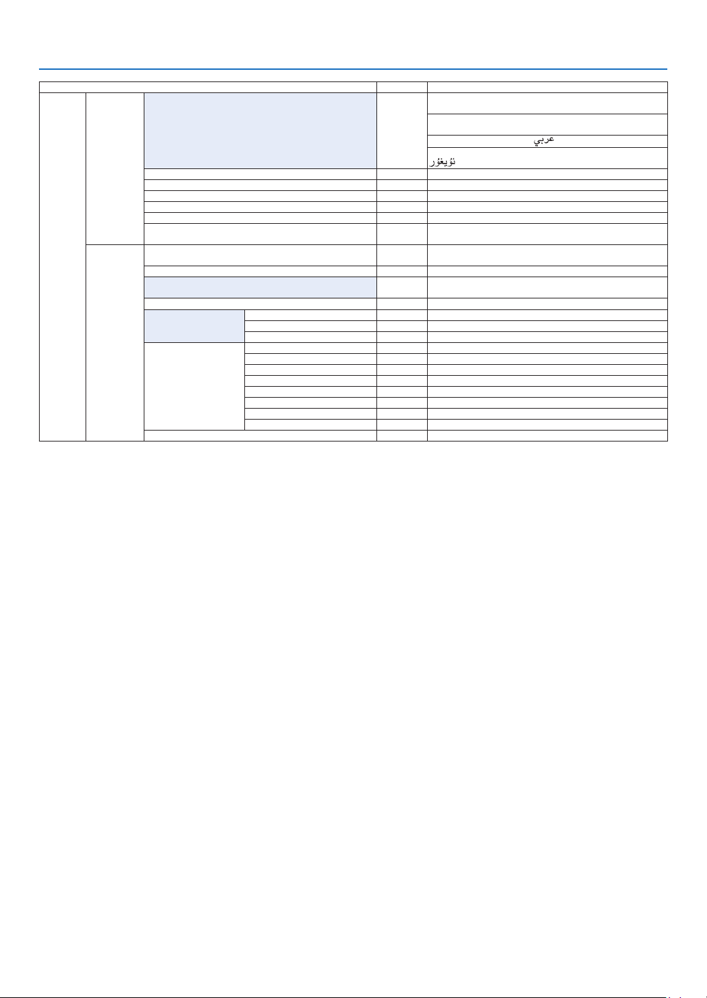
66
5. Using On-Screen Menu
Menu Item Default Options
SETUP
MENU
LANGUAGE ENGLISH
ENGLISH, DEUTSCH, FRANÇAIS, ITALIANO, ESPAÑOL, SVENSKA,
日本語
DANSK, PORTUGUÊS, ČEŠTINA, MAGYAR, POLSKI,
NEDERLANDS, SUOMI
NORSK, TÜRKÇE, РУССКИЙ,
, Ελληνικά, 中文, 한국어
ROMÂNĂ, HRVATSKA, БЪЛГАРСКИ, INDONESIA, , ไทย,
, 繁體中文
COLOR SELECT COLOR COLOR, MONOCHROME
INPUT DISPLAY ON OFF, ON
MESSAGE DISPLAY ON OFF, ON
ID DISPLAY ON OFF, ON
3D CAUTION MESSAGE ON OFF, ON
DISPLAY TIME
AUTO 45
SEC
MANUAL, AUTO 5 SEC, AUTO 15 SEC, AUTO 45 SEC
INSTALLATION
ORIENTATION AUTO
AUTO, DESKTOP FRONT, CEILING REAR, DESKTOP REAR,
CEILING FRONT
SCREEN TYPE FREE FREE, 4:3 SCREEN, 16:9 SCREEN, 16:10 SCREEN
WALL COLOR OFF
OFF, BLACKBOARD, BLACKBOARD (GRAY), LIGHT YELLOW, LIGHT
GREEN, LIGHT BLUE, SKY BLUE, LIGHT ROSE, PINK
FAN MODE AUTO AUTO, HIGH
LIGHT MODE
LIGHT MODE NORMAL NORMAL, ECO1, ECO2
CONSTANT BRIGHTNESS OFF OFF, ON
ADJUST 20–100%
REF� WHITE BALANCE
CONTRAST R
CONTRAST G
CONTRAST B
BRIGHTNESS R
BRIGHTNESS G
BRIGHTNESS B
UNIFORMITY R
UNIFORMITY B
3D GLASSES DLP® Link DLP® Link, OTHERS
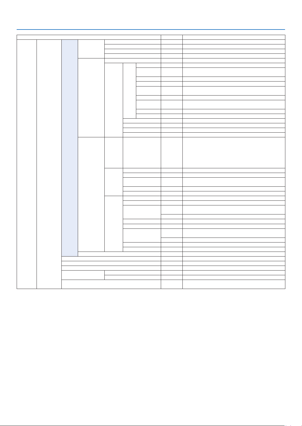
67
5. Using On-Screen Menu
Menu Item Default Options
SETUP CONTROL
TOOLS
ADMINISTRA-
TOR MODE
MENU MODE ADVANCED ADVANCED, BASIC
NOT SAVE SETTING VALUES OFF OFF, ON
NEW PASSWORD
CONFIRM PASSWORD
PROGRAM
TIMER
ENABLE OFF OFF, ON
SETTINGS
EDIT
ACTIVE OFF, ON
DAY
SUN, MON, TUE, WED, THU, FRI, SAT, MON-FRI, MON-SAT, EVERY
DAY
TIME
FUNCTION POWER, INPUT, LIGHT MODE
ADVANCED
SETTINGS
POWER OFF, ON
INPUT
HDMI, DisplayPort, BNC, BNC(CV), BNC(Y/C), COMPUTER,
HDBaseT, SLOT
LIGHT MODE NORMAL, ECO1, ECO2
REPEAT OFF, ON
DELETE
UP
DOWN
BACK
DATE AND TIME
SETTINGS
TIME
ZONE
SETTIMGS
GMT
-12:00, -11:30, -11:00, -10:30, -10:00, -09:30, -09:00, -08:30,
-08:00, -07:30, -07:00, -06:30, -06:00, -05:30, -05:00, -04:30,
-04:00, -03:30, -03:00, -02:30, -02:00, -01:30, -01:00, -00:30,
00:00, +00:30, +01:00, +01:30, +02:00, +02:30, +03:00, +03:30,
+04:00, +04;30, +05:00, +05:30, +06:00, +06:30, +07:00, +07:30,
+08:00, +08:30, +09:00, +09:30, +10:00, +10:30, +11:00, +11:30,
+12:00, +12:30, +13:00
DATE
AND TIME
SETTINGS
DATE MM/DD/YYYY
TIME HH:MM
INTERNET TIME
SERVER
OFF, ON
IP ADDRESS
UPDATE
SUMMER
TIME
SETTINGS
ENABLE OFF, ON
MON(START) 1, 2, 3, 4, 5, 6, 7, 8, 9, 10, 11, 12
DAY(START)
FIRST WEEK, SECOND WEEK, THIRD WEEK, FOURTH WEEK, LAST
WEEK
SUN, MON, TUE, WED, THU, FRI, SAT
TIME(START)
MON(EXIT) 1, 2, 3, 4, 5, 6, 7, 8, 9, 10, 11, 12
DAY(EXIT)
FIRST WEEK, SECOND WEEK, THIRD WEEK, FOURTH WEEK, LAST
WEEK
SUN, MON, TUE, WED, THU, FRI, SAT
TIME(EXIT)
TIME DIFFERENCE +01:00, +00:30, -00:30, -01:00
MOUSE
(Note) Cannot be used for this device�
CONTROL PANEL LOCK OFF OFF, ON
SECURITY OFF OFF, ON
COMMUNICATION SPEED 38400bps 4800bps, 9600bps, 19200bps, 38400bps, 115200bps
CONTROL ID
CONTROL ID NUMBER 1 1–254
CONTROL ID OFF OFF, ON
REMOTE SENSOR
FRONT/
BACK
FRONT/BACK, FRONT, BACK, HDBase-T
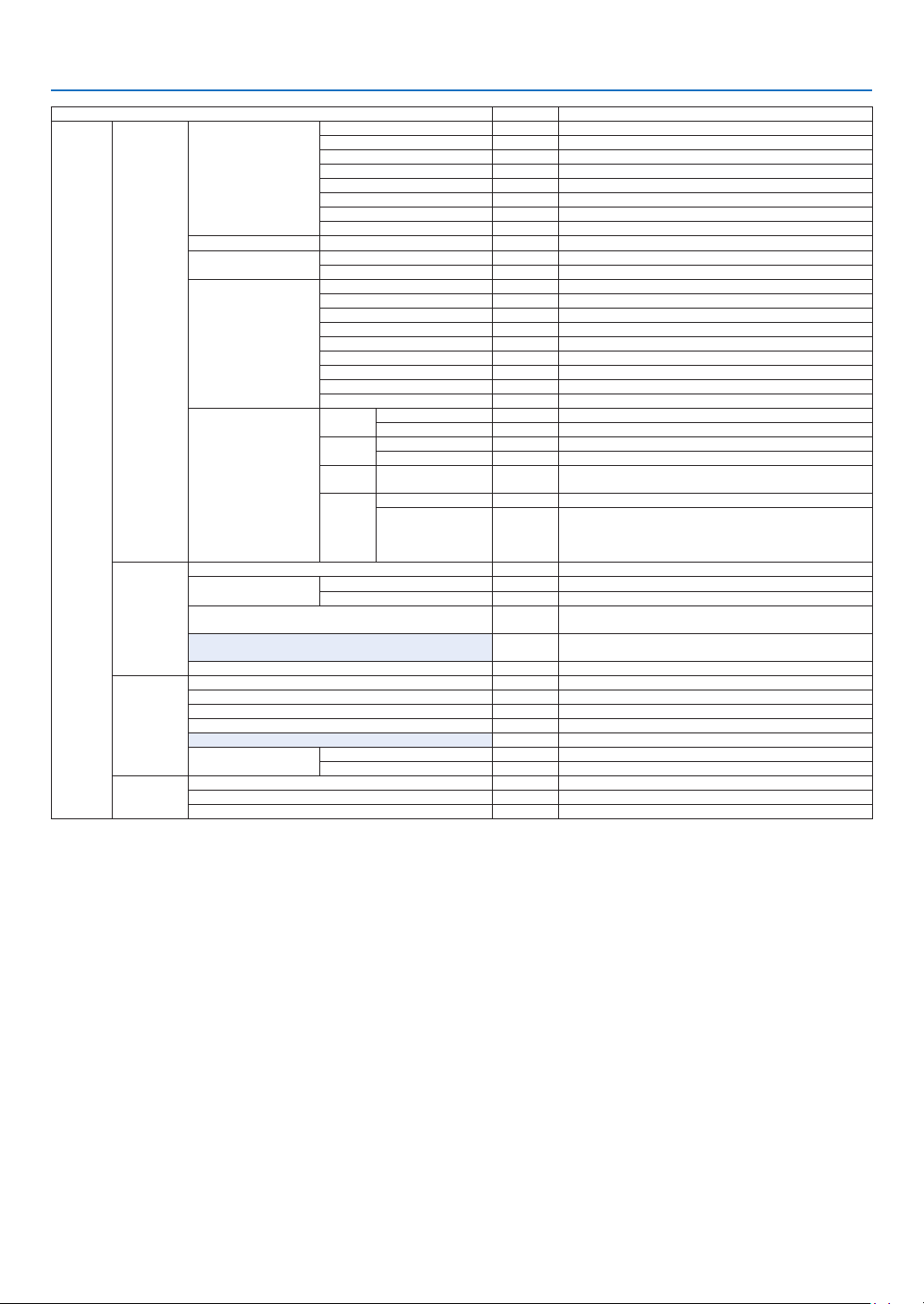
68
5. Using On-Screen Menu
Menu Item Default Options
SETUP
NETWORK
SETTINGS
WIRED LAN
PROFILES DISABLE, PROFILE 1, PROFILE 2
DHCP OFF, ON
IP ADDRESS
192�168�0�10
SUBNET MASK 255�255�255�0
GATEWAY 192�168�0�1
AUTO DNS OFF, ON
DNS CONFIGURATION
RECONNECT
PROJECTOR NAME PROJECTOR NAME PX602UL Series
DOMAIN
HOST NAME necpj
DOMAIN NAME
ALERT MAIL
ALERT MAIL OFF, ON
HOST NAME
DOMAIN NAME
SENDER'S ADDRESS
SMTP SERVER NAME
RECIPIENT'S ADDRESS 1
RECIPIENT'S ADDRESS 2
RECIPIENT'S ADDRESS 3
TEST MAIL
NETWORK SERVICE
HTTP
SERVER
NEW PASSWORD
CONFIRM PASSWORD
PJLink
NEW PASSWORD
CONFIRM PASSWORD
AMX
BEACON
OFF, ON
CRESTRON
ROOMVIEW OFF, ON
CRESTRON
CONTROL (ENABLE,
CONTROLLER IP
ADDRESS, IP ID)
SOURCE
OPTIONS
AUTO ADJUST NORMAL OFF, NORMAL, FINE
COLOR SYSTEM
BNC(VIDEO) AUTO
AUTO, NTSC3�58, NTSC4�43, PAL, PAL-M, PAL-N, PAL60, SECAM
BNC(Y/C) AUTO AUTO, NTSC3�58, NTSC4�43, PAL, PAL-M, PAL-N, PAL60, SECAM
DEFAULT INPUT SELECT LAST
LAST, AUTO, HDMI, DisplayPort, BNC, BNC(CV), BNC(Y/C),
COMPUTER, HDBaseT, SLOT
CLOSED CAPTION OFF
OFF, CAPTION1, CAPTION2, CAPTION3, CAPTION4, TEXT1, TEXT2,
TEXT3, TEXT4
BACKGROUND BLUE BLUE, BLACK, LOGO
POWER
OPTIONS
STANDBY MODE NORMAL NORMAL, NETWORK STANDBY
DIRECT POWER ON OFF OFF, ON
AUTO POWER ON SELECT OFF OFF, HDMI, DisplayPort, COMPUTER, HDBaseT, SLOT
AUTO POWER OFF 1:00 OFF, 0:05, 0:10, 0:15, 0:20, 0:30, 1:00
OFF TIMER OFF OFF, 0:30, 1:00, 2:00, 4:00, 8:00, 12:00, 16:00
SLOT POWER
PROJECTOR ON ON OFF, ON
PROJECTOR STANDBY ENABLE DISABLE, ENABLE
RESET
CURRENT SIGNAL
ALL DATA
ALL DATA (INCLUDING ENTRY LIST)
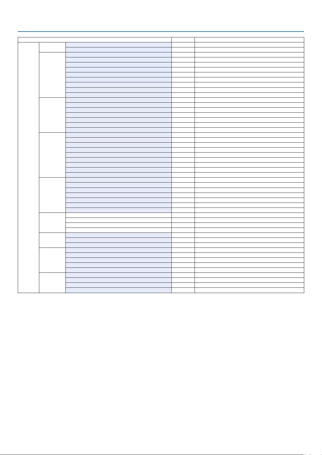
69
5. Using On-Screen Menu
Menu Item Default Options
INFO�
USAGE TIME
LIGHT HOURS USED
TOTAL CARBON SAVINGS
SOURCE(1)
INPUT TERMINAL
RESOLUTION
HORIZONTAL FREQUENCY
VERTICAL FREQUENCY
SYNC TYPE
SYNC POLARITY
SCAN TYPE
SOURCE NAME
ENTRY NO�
SOURCE(2)
SIGNAL TYPE
VIDEO TYPE
BIT DEPTH
VIDEO LEVEL
LINK RATE
LINK LANE
3D FORMAT
SOURCE(3)
INPUT TERMINAL
RESOLUTION
HORIZONTAL FREQUENCY
VERTICAL FREQUENCY
SYNC TYPE
SYNC POLARITY
SCAN TYPE
SOURCE NAME
ENTRY NO�
SOURCE(4)
SIGNAL TYPE
VIDEO TYPE
BIT DEPTH
VIDEO LEVEL
LINK RATE
LINK LANE
3D FORMAT
WIRED LAN
IP ADDRESS
SUBNET MASK
GATEWAY
MAC ADDRESS
VERSION(1)
FIRMWARE
DATA
SUB-CPU
OTHERS
DATE TIME
PROJECTOR NAME
MODEL NO�
SERIAL NUMBER
CONTROL ID (when [CONTROL ID] is set)
HDBaseT
SIGNAL QUALITY
OPERATION MODE
LINK STATUS
HDMI STATUS

70
5. Using On-Screen Menu
❹ Menu Descriptions & Functions [INPUT]
HDMI
ThisprojectsthevideoofthedeviceconnectedtotheHDMIINterminal.
DisplayPort
ThisprojectsthevideoofthedeviceconnectedtotheDisplayPortINterminal.
BNC
Thisprojectsthevideoofthedeviceconnectedtothevideoinputterminal.
(ThisprojectstheanalogRGBsignalorcomponentsignal.)
BNC(CV)
ThisprojectsthevideoofthedeviceconnectedtotheBNC(CV)videoinputterminal.
(Thisprojectsthecompositevideosignal.)
BNC(Y/C)
ThisprojectsthevideoofthedeviceconnectedtotheBNC(Y/C)videoinputterminal.
(ThisprojectstheS-videosignal.)
COMPUTER
ThisprojectsthevideoofthedeviceconnectedtotheCOMPUTER1INterminal.
(ThisprojectstheanalogRGBsignalorcomponentsignal.)
HDBaseT
ProjectingtheHDBaseTorWIREDLANsignal.
SLOT
Projectsthepictureviatheoptionalboard(soldseparately)insertedintotheSLOT.
ENTRY LIST
Displaysalistofsignals.Seethefollowingpages.
TEST PATTERN
Closesthemenuandswitchestothetestpatternscreen.
Selectthepatternusingthe◀▶buttons.
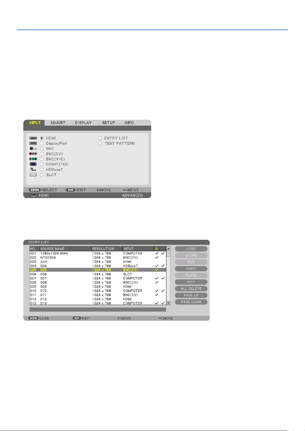
71
5. Using On-Screen Menu
UsingtheEntryList
Whenanysourceadjustmentsaremade,theadjustmentsareautomaticallyregisteredintheEntryList.The(adjust-
mentvaluesof)registeredsignalscanbeloadedfromtheEntryListwhenevernecessary.
However,onlyupto100patternscanberegisteredintheEntryList.When100patternshavebeenregisteredinthe
EntryList,anerrormessageisthendisplayedandnoadditionalpatternscanberegistered.Youshouldthusdelete
(adjustmentvaluesof)signalsthatarenolongerneeded.
DisplayingtheEntrylist
1. Press the MENU button.
Themenuwillbedisplayed.
2. Press the ◀ or ▶buttontoselect[INPUT].
TheINPUTlistwillbedisplayed.
3. Use the ◀, ▶, ▲, or ▼toselect[ENTRYLIST]andpresstheENTERbutton.
TheENTRYLISTwindowswillbedisplayed.
IftheENTRYLISTwindowisnotdisplayed,switchthemenuto[ADVANCED].
Toswitchthemenubetween[ADVANCED]and[BASIC],select[SETUP]→[CONTROL]→[TOOLS]→[ADMIN-
ISTRATORMODE]→[MENUMODE].(→page99)
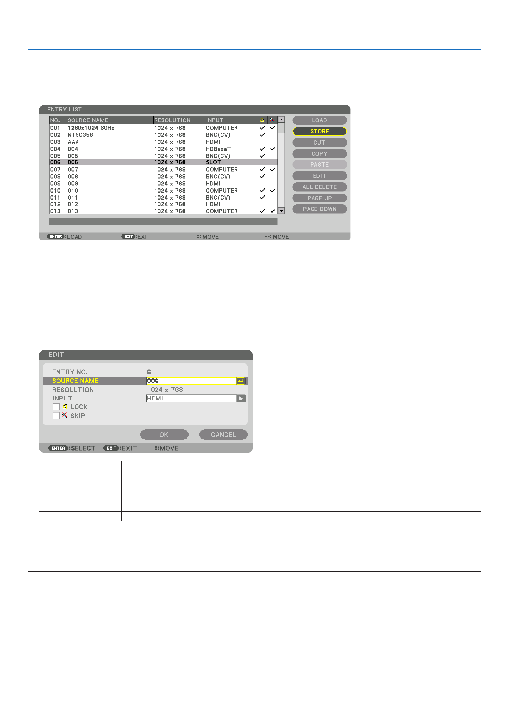
72
5. Using On-Screen Menu
EnteringthecurrentlyprojectedsignalintotheEntryList[STORE]
1. Press the ▲ or ▼ button to select any number.
2. Press the ◀ or ▶buttontoselect[STORE]andpresstheENTERbutton.
CallingupasignalfromtheEntryList[LOAD]
Pressthe▲ or ▼buttontoselectasignalandpresstheENTERbutton.
EditingasignalfromtheEntryList[EDIT]
1. Press the ▲ or ▼ button to select a signal you wish to edit.
2. Press the ◀, ▶, ▲, or ▼buttontoselect[EDIT]andpresstheENTERbutton.
TheEditwindowwillbedisplayed.
SOURCENAME Enterasignalname.Upto18alphanumericcharacterscanbeused.
INPUT Theinputterminalcanbechanged.SwitchingbetweenHDMI/DisplayPort/BNC/BNC(CV)/
BNC(Y/C)/Computer/HDBaseT/SLOTispossible.
LOCK Setso that the selectedsignalcannot be deleted when [ALL DELETE] is executed.The
changesmadeafterLOCKexecutioncannotbesaved.
SKIP Setsothattheselectedsignalwillbeskippedduringautosearch.
3. Settheaboveitemsandselect[OK]andpresstheENTERbutton.
NOTE: The input terminal cannot be changed to the currently projected signal.

73
5. Using On-Screen Menu
CuttingasignalfromtheEntryList[CUT]
1. Press the ▲ or ▼ button to select a signal you wish to delete.
2. Press the ◀, ▶, ▲, or ▼buttontoselect[CUT]andpresstheENTERbutton.
ThesignalwillbedeletedfromtheEntryListandthedeletedsignalwillbedisplayedontheclipboardatthebottom
oftheEntryList.
NOTE:
• Thecurrentlyprojectedsignalcannotbedeleted.
• Whenthelockedsignalisselected,itwillbedisplayedingraywhichindicatesitisnotavailable.
TIP:
• DataontheclipboardcanbepassedontotheEntryList.
• DataontheclipboardwillnotbelostaftertheEntryListisclosed.
CopyingandpastingasignalfromtheEntryList[COPY]/[PASTE]
1. Press the ▲ or ▼ button to select a signal you wish to copy.
2. Press the ◀, ▶, ▲, or ▼buttontoselect[COPY]andpresstheENTERbutton.
ThecopiedsignalwillbedisplayedontheclipboardatthebottomoftheEntryList.
3. Press the ◀ or ▶ button to move to the list.
4. Press the ▲ or ▼ button to select a signal.
5. Press the ◀, ▶, ▲, or ▼buttontoselect[PASTE]andpresstheENTERbutton.
Dataontheclipboardwillbepastedtothesignal.
DeletingallthesignalsfromtheEntryList[ALLDELTE]
1. Press the ◀, ▶, ▲, or ▼buttontoselect[ALLDELETE]andpresstheENTERbutton.
Theconrmationmessagewillbedisplayed.
2. Press the ◀ or ▶buttontoselect[YES]andpresstheENTERbutton.
NOTE: The locked signal cannot be deleted.
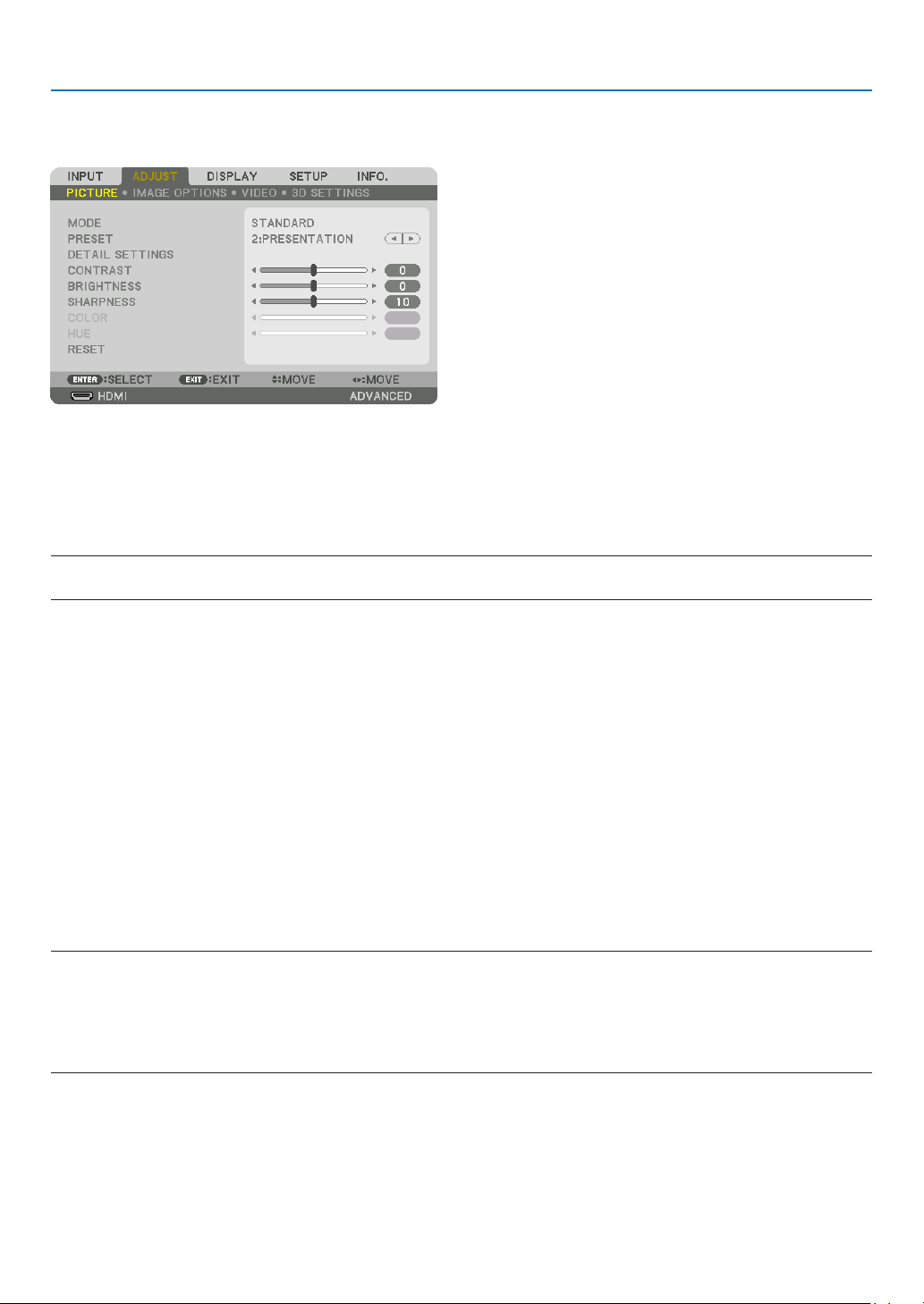
74
5. Using On-Screen Menu
❺ Menu Descriptions & Functions [ADJUST]
[PICTURE]
[MODE]
Thisfunctionallowsyoutodeterminehowtosavesettingsfor[DETAILSETTINGS]of[PRESET]foreachinput.
STANDARD ������������ Saves settings for each item of [PRESET] (Preset 1 through 7)
PROFESSIONAL
����� Saves all the settings of [PICTURE] for each input�
NOTE:
• When[TESTPATTERN]isdisplayed,[MODE]cannotbeselected.
[PRESET]
Thisfunctionallowsyoutoselectoptimizedsettingsforyourprojectedimage.
Youcanadjustneutraltintforyellow,cyanormagenta.
Therearesevenfactorypresetsoptimizedforvarioustypesofimages.Youcanalsouse[DETAILSETTINGS]toset
useradjustablesettingstocustomizeeachgammaorcolor.
Yoursettingscanbestoredin[PRESET1]to[PRESET7].
HIGH-BRIGHT �������� Recommended for use in a brightly lit room�
PRESENTATION ����� Recommended for making a presentation using a PowerPoint file�
VIDEO �������������������� Recommended for typical TV program viewing�
MOVIE ������������������� Recommended for movies�
GRAPHIC ��������������� Recommended for graphics�
sRGB ��������������������� Standard color values
DICOM SIM� ���������� Recommended for DICOM simulation format�
NOTE:
• The[DICOMSIM.]optionisfortraining/referenceonlyandshouldnotbeusedforactualdiagnosis.
• DICOMstandsforDigitalImagingandCommunicationsinMedicine.ItisastandarddevelopedbytheAmericanCollegeofRadiol-
ogy(ACR)andtheNationalElectricalManufacturersAssociation(NEMA).
Thestandardspecieshowdigitalimagedatacanbemovedfromsystemtosystem.
• Adjustmentmaynotworkdependingoninputsignal.
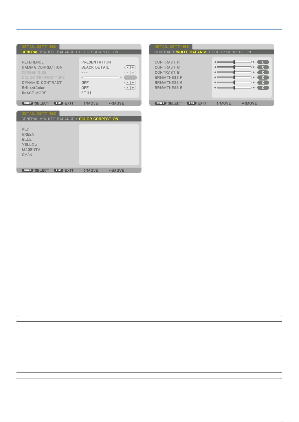
75
5. Using On-Screen Menu
[DETAILSETTINGS]
[GENERAL]
StoringYourCustomizedSettings[REFERENCE]
Thisfunctionallowsyoutostoreyourcustomizedsettingsin[PRESET1]to[PRESET7].
First,selectabasepresetmodefrom[REFERENCE],thenset[GAMMACORRECTION]and[COLORTEMPERATURE].
HIGH-BRIGHT �������� Recommended for use in a brightly lit room�
PRESENTATION ����� Recommended for making a presentation using a PowerPoint file�
VIDEO �������������������� Recommended for typical TV program viewing�
MOVIE ������������������� Recommended for movies�
GRAPHIC ��������������� Recommended for graphics�
sRGB ��������������������� Standard color values�
DICOM SIM� ���������� Recommended for DICOM simulation format�
SelectingGammaCorrectionMode[GAMMACORRECTION]
Eachmodeisrecommendedfor:
DYNAMIC �������������� Creates a high-contrast picture�
NATURAL ��������������� Natural reproduction of the picture�
BLACK DETAIL ������� Emphasizes detail in dark areas of the picture�
NOTE:Thisfunctionisnotavailablewhen[DICOMSIM.]isselectedfor[DETAILSETTINGS].
SelectingScreenSizeforDICOMSIM[SCREENSIZE]
Thisfunctionwillperformgammacorrectionappropriateforthescreensize.
LARGE ������������������� For screen size of 150"
MEDIUM
���������������� For screen size of 100"
SMALL
������������������� For screen size of 50"
NOTE:Thisfunctionisavailableonlywhen[DICOMSIM.]isselectedfor[DETAILSETTINGS].

76
5. Using On-Screen Menu
AdjustingColorTemperature[COLORTEMPERATURE]
Thisoptionallowsyoutoselectthecolortemperatureofyourchoice.
Avaluebetween5000Kand10500Kcanbesetin100Kunits.
NOTE:When[PRESENTATION]or[HIGH-BRIGHT]isselectedin[REFERENCE],thisfunctionisnotavailable.
AdjustingBrightnessandContrast[DYNAMICCONTRAST]
If[ON]isselected,themostoptimalcontrastratioisusedaccordingtothepicture.
NOTE:
• Dependingontheconditions,projectorsettingssuchas[DYNAMICCONTRAST]maynotbeabletobeselected.
[BrilliantColor]
Selectsthebrightnessofthecolorwhite.
Selectingoptionsfrom[MEDIUM]to[HIGH]increasesthebrightnessofthecolorwhite.
NOTE:
• Ifunder[REFERENCE],[HIGH-BRIGHT]or[PRESENTATION]areselected,[BrilliantColor]cannotbechanged.
SelectingStillImageModeorMovieMode[IMAGEMODE]
Thisfunctionallowsyoutoselectthestillimagemodeorthemoviemode.
STILL ��������������������� This mode is for a still image�
MOVIE ������������������� This mode is for a movie�
NOTE:
• Thismodemaynotbeavailabledependingoninputsignal.
AdjustingWhiteBalance[WHITEBALANCE]
Thisallowsyoutoadjustthewhitebalance.Contrastforeachcolor(RGB)toadjustthewhitelevelofthescreen;
Brightnessforeachcolor(RGB)isusedtoadjusttheblacklevelofthescreen.
[COLORCORRECTION]
Correctsthecolorforallsignals.
Adjuststhetoneforthecolorsred,green,blue,yellow,magentaandcyan.
RED HUE +Direction Magentadirection
−Direction Yellowdirection
SATURATION +Direction Vivid
−Direction Weak
GREEN HUE
+Direction Yellowdirection
−Direction Cyandirection
SATURATION +Direction Vivid
−Direction Weak
BLUE HUE
+Direction Cyandirection
−Direction Magentadirection
SATURATION +Direction Vivid
−Direction Weak
YELLOW HUE
+Direction Reddirection
−Direction Greendirection
SATURATION +Direction Vivid
−Direction Weak
MAGENTA HUE
+Direction Bluedirection
−Direction Reddirection
SATURATION +Direction Vivid
−Direction Weak

77
5. Using On-Screen Menu
CYAN HUE +Direction Greendirection
−Direction Bluedirection
SATURATION +Direction Vivid
−Direction Weak
[CONTRAST]
Adjuststheintensityoftheimageaccordingtotheincomingsignal.
[BRIGHTNESS]
Adjuststhebrightnesslevelorthebackrasterintensity.
[SHARPNESS]
Controlsthedetailoftheimage.
[COLOR]
Increasesordecreasesthecolorsaturationlevel.
[HUE]
Variesthecolorlevelfrom+/−greento+/−blue.Theredlevelisusedasreference.
Inputsignal CONTRAST BRIGHTNESS SHARPNESS COLOR HUE
RGBsystemof“COMPUTER/
DisplayPort/HDMI/HDBaseT”
Ye s Ye s Ye s No No
COMPONENTsystemof“COMPUTER/
DisplayPort/HDMI/HDBaseT”
Ye s Ye s Ye s Ye s Ye s
CompositeVideo/S-Video Yes Ye s Ye s Ye s Ye s
Yes=Adjustable,No=Notadjustable
NOTE:
• When[TESTPATTERN]isdisplayed,[CONTRAST],[BRIGHTNESS],[SHARPNESS],[COLOR]and[HUE]cannotbeadjusted.
[RESET]
Thesettingsandadjustmentsfor[PICTURE]willbereturnedtothefactorysettingswiththeexceptionofthefollowing;
Presetnumbersand[REFERENCE]withinthe[PRESET]screen.
Thesettingsandadjustmentsunder[DETAILSETTINGS]withinthe[PRESET]screenthatarenotcurrentlyselected
willnotbereset.
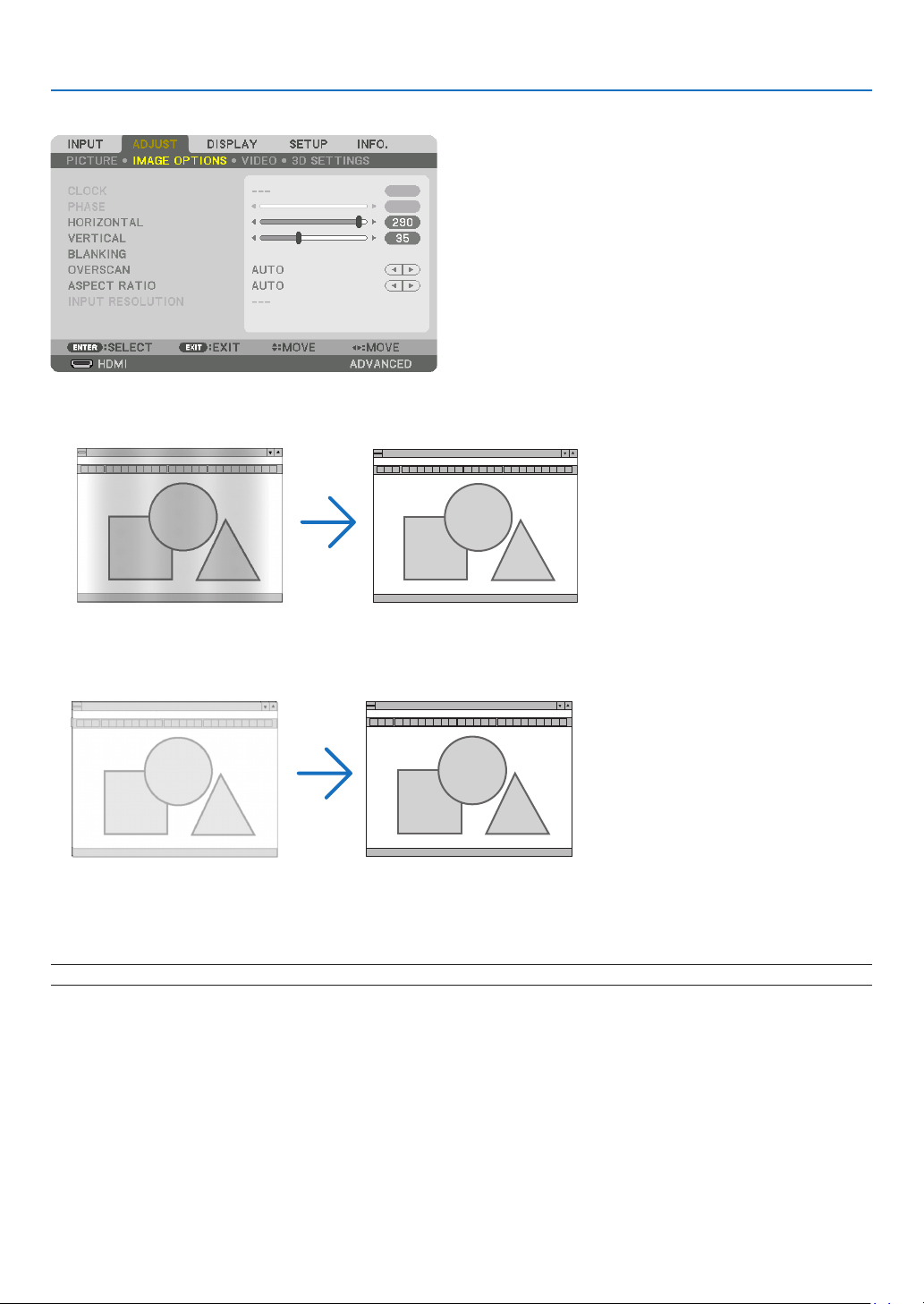
78
5. Using On-Screen Menu
[IMAGE OPTIONS]
AdjustingClockandPhase[CLOCK/PHASE]
ThisallowsyoutomanuallyadjustCLOCKandPHASE.
CLOCK ������������������� Use this item to fine tune the computer image or to remove any vertical banding that might appear� This
function adjusts the clock frequencies that eliminate the horizontal banding in the image�
This adjustment may be necessary when you connect your computer for the first time�
PHASE ������������������� Use this item to adjust the clock phase or to reduce video noise, dot interference or cross talk� (This is
evident when part of your image appears to be shimmering�)
Use [PHASE] only after the [CLOCK] is complete�
NOTE:The[CLOCK]and[PHASE]itemsareavailableforRGBsignalsonly.
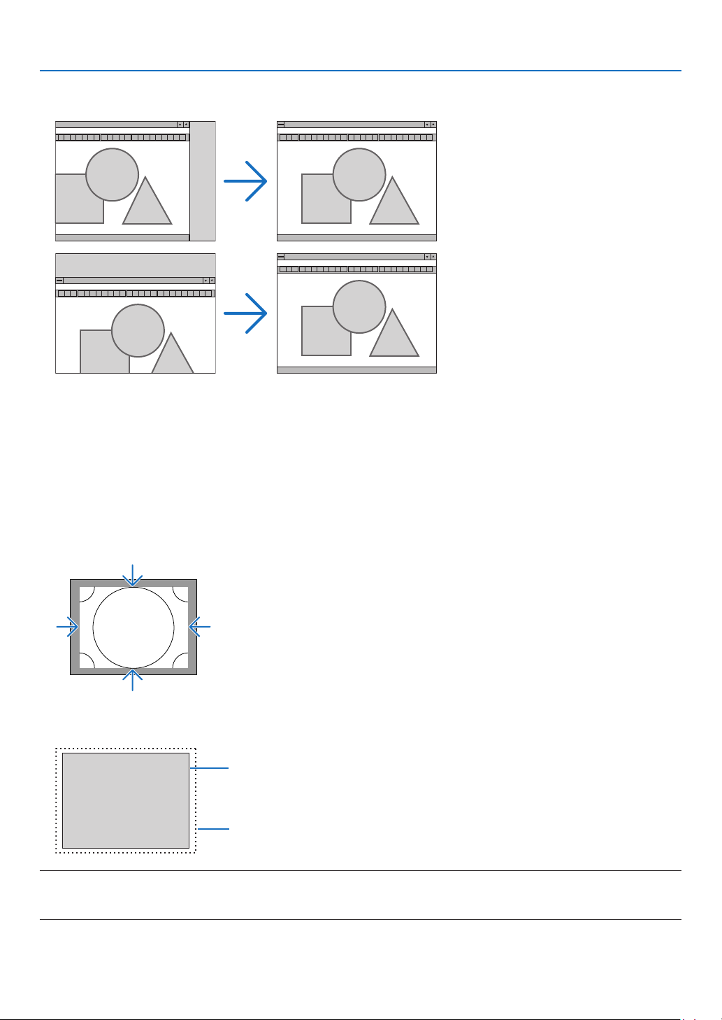
79
5. Using On-Screen Menu
AdjustingHorizontal/VerticalPosition[HORIZONTAL/VERTICAL]
Adjuststheimagelocationhorizontallyandvertically.
• Animagecanbedistortedduringtheadjustmentof[CLOCK]and[PHASE].Thisisnotmalfunction.
• Theadjustmentsfor[CLOCK], [PHASE],[HORIZONTAL],and[VERTICAL]willbestoredin memoryforthe
currentsignal.Thenexttimeyouprojectthesignalwiththesameresolution,horizontalandverticalfrequency,
itsadjustmentswillbecalledupandapplied.
Todeleteadjustmentsstoredinmemory,fromthemenu,youselect[RESET]→[CURRENTSIGNAL]andreset
theadjustments.
[BLANKING]
Adjuststhedisplayrange(blanking)atthetop,bottom,leftandrightedgesoftheinputsignal.
SelectingOverscanPercentage[OVERSCAN]
Selectoverscanpercentage(Auto,0%,5%and10%)forsignal.
Projectedimage
Overscanedby10%
NOTE:
• The[OVERSCAN]itemisnotavailable:
-when[NATIVE]isselectedfor[ASPECTRATIO].
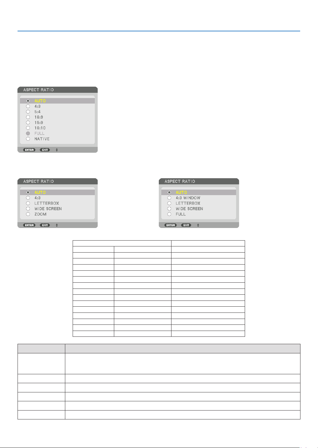
80
5. Using On-Screen Menu
SelectingtheAspectRatio[ASPECTRATIO]
Usethisfunctiontoselectthescreen’svertical:horizontalaspectratio.
Selectthescreentype(4:3screen,16:9screenor16:10screen)atthescreensettingbeforesettingtheaspectratio.
(→page97)
Theprojectorautomaticallyidentiesthesignalbeinginputandsetstheoptimumaspectratio.
For Computer signal
ForComponent/Video/S-Videosignals
Whenthescreentypeissetto4:3 Whenthescreentypeissetto16:9or16:10
Resolution AspectRatio
VGA 640×480 4:3
SVGA
800×600 4:3
XGA
1024×768 4:3
WXGA
1280×768 15:9
WXGA
1280×800 16:10
HD(FWXGA)
1366×768 approx.16:9
WXGA+ 1440×900 16:10
SXGA
1280×1024 5:4
SXGA+
1400×1050 4:3
WXGA++
1600×900 16:9
UXGA
1600×1200 4:3
WSXGA+
1680×1050 16:10
FHD(1080P)
1920×1080 16:9
WUXGA
1920×1200 16:10
WQXGA
2560×1600 16:10
Options Function
AUTO
Theprojectorwillautomaticallydeterminetheincomingsignalanddisplayitinitsaspectratio.
Theprojectormayerroneouslydeterminetheaspectratiodependingonitssignal.Ifthisoccurs,select
theappropriateaspectratiofromthefollowing.
4:3 Theimageisdisplayedin4:3aspectratio.
5:4 Theimageisdisplayedin5:4aspectratio
16:9 Theimageisdisplayedin16:9aspectratio
15:9 Theimageisdisplayedin15:9aspectratio
16:10 Theimageisdisplayedin16:10aspectratio
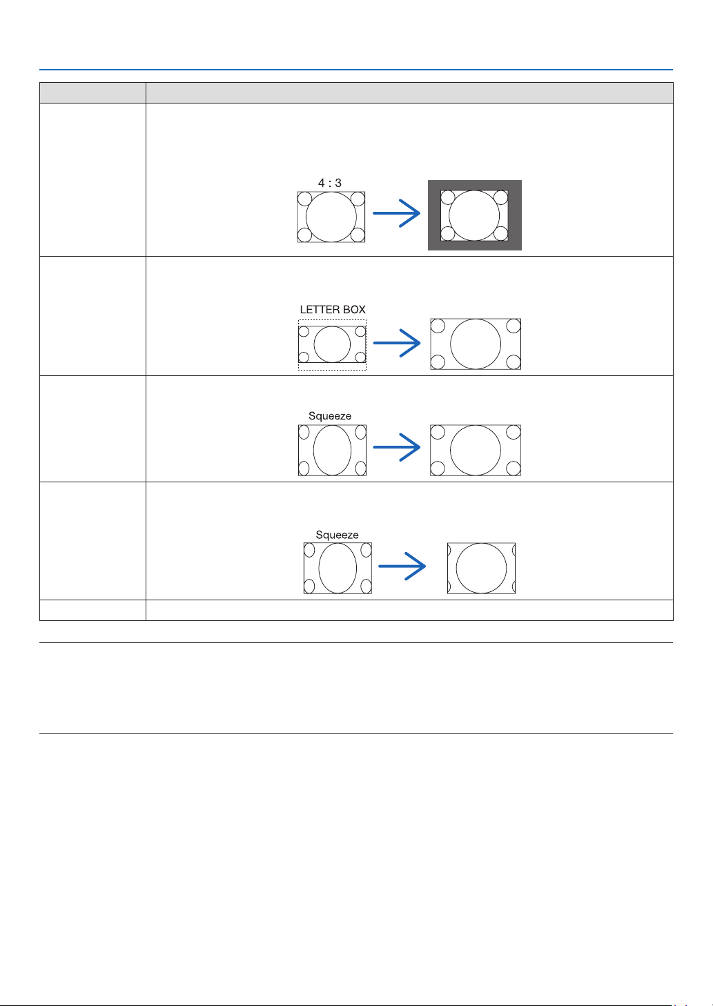
81
5. Using On-Screen Menu
Options Function
NATIVE
Theprojectordisplaysthecurrentimageinitstrueresolutionwhentheincomingcomputersignalhasa
lowerorhigherresolutionthantheprojector’snativeresolution.(→page2)
Whentheincomingcomputersignalhasahigherresolutionthantheprojector'snativeresolution,the
centerofanimagewillbedisplayed.
LETTERBOX Theimageofaletterboxsignal(16:9)isstretchedequallyinthehorizontalandverticaldirectionstotthe
screen.
WIDESCREEN Theimageofasqueezesignal(16:9)isstretchedleftandrightin16:9.
ZOOM Theimageofasqueezesignal(16:9)isstretchedleftandrightin4:3.
Partsofthedisplayedimagearecroppedattheleftandrightedgesandthereforenotvisible.
FULL Projecttofullscreensize.
TIP:
• Imagepositioncanbeadjustedverticallyusing[POSITION]whenthe[16:9],[15:9],or[16:10]aspectratiosareselected.
• Theterm“letterbox”referstoamorelandscape-orientedimagewhencomparedtoa4:3image,whichisthestandardaspect
ratio for a vide source.
Theletterboxsignalhasaspectratioswiththevistasize“1.85:1”orcinemascopesize“2.35:1”formovielm.
• Theterm“squeeze”referstothecompressedimageofwhichaspectratioisconvertedfrom16:9to4:3.
[INPUTRESOLUTION]
Theresolutionisassignedautomaticallywhentheresolutionoftheinputsignalfromthecomputervideoinputterminal
orBNCvideoinputterminal(analogRGB)cannotbedistinguished.

82
5. Using On-Screen Menu
[VIDEO]
UsingNoiseReduction[NOISEREDUCTION]
Whenprojectingavideoimage,youcanusethe[NOISEREDUCTION]functiontoreducethescreennoise(roughness
anddistortion).Thisdeviceisequippedwiththreetypesofnoisereductionfunctions.Selectthefunctionaccordingto
thetypeofnoise.Dependingonthenoiselevel,thenoisereductioneffectcanbesetto[OFF],[LOW],[MEDIUM]or
[HIGH].[NOISEREDUCTION]canbeselectedforSDTV,HDTVsignalandcomponentsignalinput.
RANDOM NR ��������� Reduces flickering random noise in an image�
MOSQUITO NR ������ Reduces mosquito noise that appears around the edges of an image during Blu-ray playback�
BLOCK NR ������������� Reduces block noise or mosaic-like patterns by selecting ON�
SelectingInterlacedProgressiveConversionProcessMode[DEINTERLACE]
Thisfunctionallowsyoutoselectaninterlaced-to-progressiveconversionprocessforvideosignals.
NORMAL ���������������� Automatically distinguishes a moving image from a static image to create a distinct image� Please select
[MOVIE] if there are any obvious jitter and noises�
MOVIE ������������������� Select when projecting moving images� This is suitable for signals with a lot of jitter and noise�
STILL ��������������������� Select when projecting static images� The video will flicker when a moving image is projected�
NOTE:ThisfunctionisnotavailablewithRGBsignals.
[CONTRASTENHANCEMENT]
Usingthecharacteristicsofthehumaneye,apicturequalitywithasenseofcontrastandresolutionisachieved.
OFF ������������������������ Suite vision is switched off�
AUTO ��������������������� Contrast and picture quality are automatically improved using the suite vision function�
NORMAL ���������������� Adjust the gain manually�

83
5. Using On-Screen Menu
[SIGNALTYPE]
SelectionofRGBandcomponentsignals.Normally,thisissetto[AUTO].Pleasechangethesettingifthecolorofthe
imageremainsunnatural.
AUTO ��������������������� Automatically distinguishes RGB and component signals�
RGB ����������������������� Switches to the RGB input�
COMPONENT ��������� Switches to the component signal input�
[VIDEOLEVEL]
SelectionofthevideosignallevelwhenconnectinganexternaldevicetotheHDMIINterminal,DisplayPortinput
terminal,andHDBaseTinputterminaloftheprojector.
AUTO ��������������������� The video level is switched automatically based on the information from the device outputting the signal�
Depending on the connected device, this setting may not be made properly� In this case, switch to [NORMAL”
or “ENHANCED” from the menu and view with the optimum setting�
NORMAL ���������������� This disables the enhanced mode�
ENHANCED ������������ This improves the image’s contrast, expressing the dark and light sections more dynamically�
SUPER WHITE ������� The video contrast is improved and the dark areas appear more dynamic�

84
5. Using On-Screen Menu
[3D SETTINGS]
Pleasereferto“3-9Projecting3Dvideos”(→page38)fortheoperation.
FORMAT
Selectthe3Dvideoformat(recording/transmissionformat).Selecttomatchthe3Dbroadcastand3Dmedia.Nor-
mally,[AUTO]isselected.Pleaseselectthe3Dinputsignalformatwhenthe3Ddetectionsignaloftheformatcannot
bedistinguished.
L/RINVERT
Invertthedisplayorderoftheleftandrightvideos.
Select[ON]ifyoufeeluncomfortablewiththe3Ddisplaywhen[OFF]isselected.

85
5. Using On-Screen Menu
❻ Menu Descriptions & Functions [DISPLAY]
[PIP/PICTURE BY PICTURE]
SUBINPUT
Selecttheinputsignaltobedisplayedinthesub-display.
Pleasereferto“4-2DisplayingTwoPicturesattheSameTime”(→page52)fordetailsontheoperation.
MODE
SelecteitherPIPorPICTUREBYPICTUREwhenswitchingto2-screendisplay.
PICTURESWAP
Thevideosinthemaindisplayandsub-displaywillbeswitched.
Pleasereferto“4-2DisplayingTwoPicturesattheSameTime”(→page54)fordetails.
PIPSETTING
Selectthedisplayposition,positionadjustmentandsizeofthesub-displayinthePIPscreen.
START POSITION ��� Selection of the display position of the sub-display when switching to the PIP screen�
HORIZONTAL POSITION
������������������������������ Adjust the display position of the sub-display in the horizontal direction� The respective corners will serve
as reference points�
VERTICAL POSITION
������������������������������ Adjust the display position of the sub-display in the vertical direction� The respective corners will serve as
reference points�
SIZE ����������������������� Select the display size of the sub-display�
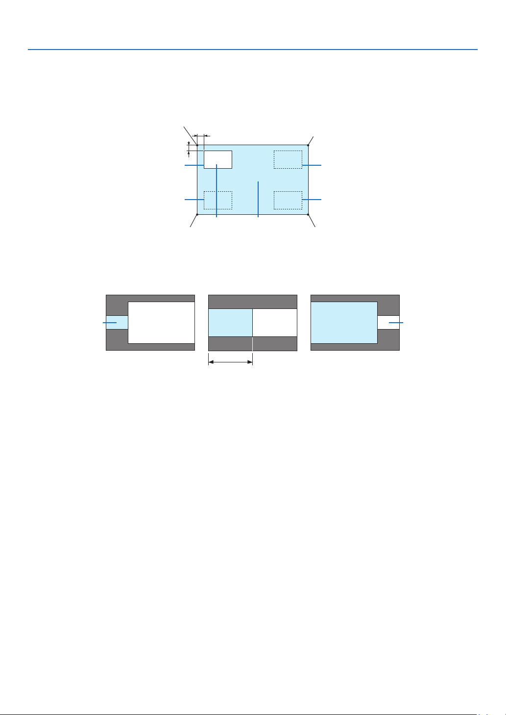
86
5. Using On-Screen Menu
TIP:
Thehorizontalpositionandverticalpositionaretheamountofmovementfromthereferencepoints.Forexample,whenTOP-LEFT
is adjusted, the position is displayed with the same amount of movement even if displayed with other starting positions.
The maximum amount of movement is half the resolution of the projector.
Referencepoint
Adjustusingthehorizon-
talposition
Sub-display Maindisplay
Referencepoint
Adjustusingtheverticalposition
TOP-LEFT TOP-RIGHT
BOTTOM-LEFT BOTTOM-RIGHT
ReferencepointReferencepoint
BORDER
Selectthedisplayboundaryofthemaindisplayandsub-displayofthe[PICTUREBYPICTURE]screen.
Displayboundary
Maindisplay
Sub-displayMaindisplay
Sub-display
MaindisplaySub-display
TIP:
• 6stepscanbeselectedonthisprojector.
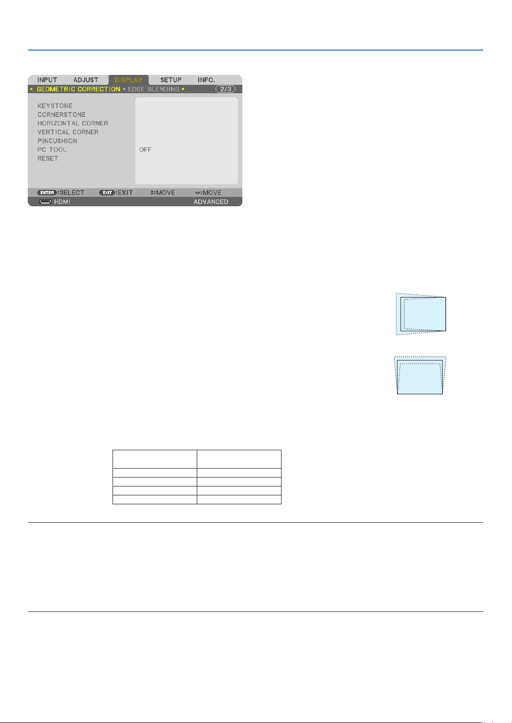
87
5. Using On-Screen Menu
[GEOMETRIC CORRECTION]
KEYSTONE
Displaythetrapezoidcorrectionscreenandadjustthetrapezoidaldistortionoftheprojectionscreen.
Todisplaythe[KEYSTONE]screen,select→[DISPLAY]→[GEOMETRICCORRECTION]→[KEYSTONE]inthe
on-screenmenu.The[GEOMETRIC CORRECTION]screencan alsobedisplayedbypressingthe3D REFORM
buttonontheremotecontrol.
HORIZONTAL ��������� Adjustments when projecting from a diagonal direction to the
screen�
VERTICAL �������������� Adjustments when projecting from the top or bottom direction to
the screen�
TILT ����������������������� Adjusts the distortion when performing trapezoidal correction with the screen moved in the vertical direction
using the lens shift�
THROW RATIO ������� Adjusts according to the projection ratio of the optional lens used�
Modelnameoflens
unit
Adjustmentrange
NP34ZL 9–13
NP35ZL 12–17
NP36ZL 12–17
NP37ZL 15–31
NOTE:
• Whenpowerissuppliedtothedevice,theadjustmentvalueofthe[KEYSTONE]usedpreviouslyisretainedevenifthegradient
of the device is changed.
• Whenclearingtheadjustmentvalueof[KEYSTONE],pressthe3DREFORMbuttonfor2ormoreseconds.
• Whensettingother[GEOMETRICCORRECTION]functions,the[KEYSTONE]menucannotbeselected.Whenperformingtrapezoidal
correction,pressthe3DREFORMbuttonfor2ormoresecondstocleartheadjustmentvalueof[GEOMETRICCORRECTION].
• Aselectricalcorrection iscarriedout by[KEYSTONE],thebrightnessmay bereducedor thescreenqualitymaydeteriorate
sometimes.
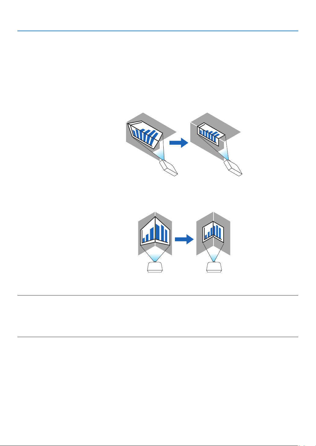
88
5. Using On-Screen Menu
CORNERSTONE
Displaythe4-pointcorrectionscreenandadjustthetrapezoidaldistortionoftheprojectionscreen.
Pleasereferto“CorrectingHorizontalandVerticalKeystoneDistortion[CORNERSTONE]”(→page32)fordetails
ontheoperation.
HORIZONTALCORNER/VERTICALCORNER
Distortioncorrectionforcornerprojectionsuchaswallsurfaces.
HORIZONTAL CORNER
������������������������������ Performs correction for projection onto a wall lying at an angle to the horizontal direction�
* Reverse angle correction is also possible�
VERTICAL CORNER
������������������������������ Performs correction for projection onto a wall lying at an angle to the vertical direction�
* Reverse angle correction is also possible�
NOTE:
• Whenthemaximumadjustmentrangeisexceeded,distortionadjustmentisdisabled.Setuptheprojectoratanoptimalangleas
the deterioration in the image quality increases as the distortion adjustment volume gets larger.
• Pleasenotethattheimagewillgooutoffocusduetothedifferenceinthedistancebetweentheupperandlowerorleftandright
sidesandthecenterofthescreenforprojectionscuttingacrosscorners.Lenseswithshortfocalpointsarealsonotrecommended
for projections cutting across corners as the image will go out of focus.
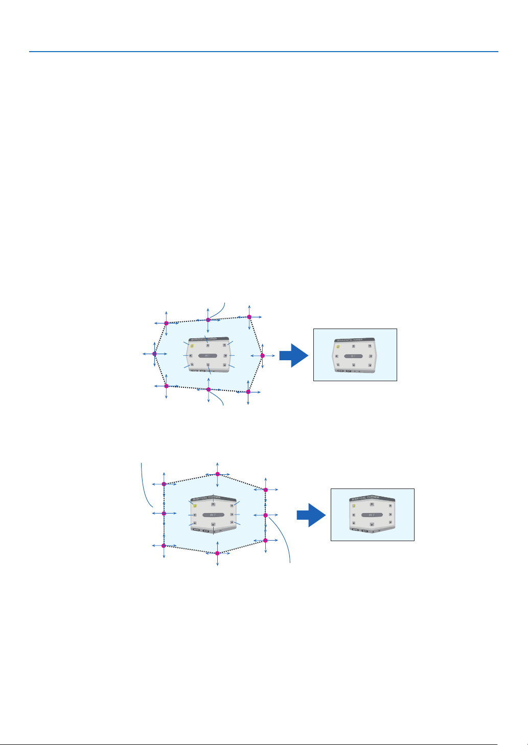
89
5. Using On-Screen Menu
Adjustment method
1. Alignthecursorwiththe[HORIZONTALCORNER]or[VERTICALCORNER]ofthe[GEOMETRICCORREC-
TION]menuandthenpresstheENTERbutton.
• Theadjustmentscreenwillbedisplayed.
2. Press the ▼▲◀▶ buttons to align the cursor (yellow box) with the target adjustment point and then press
the ENTER button.
• Thecursorwillchangeintoanadjustmentpoint(yellowincolor).
3. Press the ▼▲◀▶buttonstoadjustthecornersorsidesofthescreenandthenpresstheENTERbutton.
• Theadjustmentpointwillgobacktobeingacursor(yellowbox).
Explanationofscreentransition
• Theadjustmentpointsofthefourcorners(a,c,fandhinthedrawing)willmoveindependently.
• Thefollowingadjustmentpointsdifferatthe[HORIZONTALCORNER]and[VERTICALCORNER].
HORIZONTALCORNER:WhenPointbinthedrawingismoved,andtheuppersideandPointgaremoved,the
lowersidewillmoveinaparallelmanner.
VERTICALCORNER:WhenPointdinthedrawingismoved,andtheleftsideandPointearemoved,theright
sidewillmoveinaparallelmanner.
[Adjustmentpointsofthe[HORIZONTALCORNER]screenandmovementpointsoftheprojectionscreen]
a
b
b
c
d
e
f
g
h
a
c
d
e
f
g
h
PointbwillbedisplacedinaparallelmanneratthesametimeasPointsa,b,c
PointgwillbedisplacedinaparallelmanneratthesametimeasPointsf,g,h
[Adjustmentpointsofthe[VERTICALCORNER]screenandmovementpointsoftheprojectionscreen]
a
a
b
b
c
c
d
d
e
e
f
f
g
g
h
h
PointdwillbedisplacedinaparallelmanneratthesametimeasPointsa,d,f
PointewillbedisplacedinaparallelmanneratthesametimeasPointsf,g,h
4. StartfromStep2onwardstoadjusttheotherpoints.
5. When the adjustment is completed, press the ▼▲◀▶buttonsto alignthecursorwiththe[EXIT] inthe
adjustment screen and then press theENTER button.
• Switchtothe[GEOMETRICCORRECTION]menuscreen.

90
5. Using On-Screen Menu
PINCUSHION
Adjustthecurvedistortionoftheprojectionscreen.
TOP ������������������������ Adjust the curve distortion of the upper edge of the projection
screen�
BOTTOM ���������������� Adjust the curve distortion of the lower edge of the projection
screen�
LEFT ���������������������� Adjust the curve distortion of the left edge of the projection screen�
RIGHT �������������������� Adjust the curve distortion of the right edge of the projection
screen�
TOP
LEFT RIGHT
BOTTOM
PCTOOL(Forfuturesupport)
Recallthegeometriccorrectiondatathatisregisteredintheprojectorbeforehand.
Therearethreetypesofregistereddata.
NOTE:
• KEYSTONE,CORNERSTONE,andPINCUSHIONcannotbeselectedwhensettingthegeometriccorrectionusingaPCtool.
• Toclearthe[GEOMETRICCORRECTION]datathathasbeensetup,pressthe3DREFORMbuttonfor2ormoreseconds.
• Aselectricalcorrectioniscarriedoutingeometriccorrection,thebrightnessmaybeaffectedandthepicturequalitymaybe
degraded.
RESET
ResettheadjustmentvaluethathasbeensetupinGEOMETRICCORRECTION(returntotheinitialvalue).

91
5. Using On-Screen Menu
[EDGE BLENDING]
Thisadjuststheedges(boundaries)oftheprojectionscreenwhenprojectinghighresolutionvideosusingacombina-
tionofseveralprojectorsintheup,down,leftandrightpositions.
MODE
ThisenablesordisablestheEDGEBLENDINGfunction.
WhenMODEissettoON,theTOP,BOTTOM,LEFT,RIGHTandBLACKLEVELsettingscanbeadjusted.
TOP/BOTTOM/LEFT/RIGHT
ThisselectstheEDGEBLENDINGlocationsontheleft,right,topandbottomonthescreen.
Thefollowingsettingscanbeadjustedwhenanitemisselected.(→page57)
CONTROL �������������� Enable TOP, BOTTOM, LEFT and RIGHT functions�
MARKER ���������������� Set whether to display marker or not when adjusting the range and display position� When turned on, a
magenta marker for adjusting the range adjustment and a green marker for adjusting the display position
will be displayed�
RANGE ������������������� Adjust the range (width) of the edge blending�
POSITION �������������� Adjust the display position of the edge blending�
BLACKLEVEL
Dividethescreenintoninepartsandkeeptheblackleveluniformforeachprojector.
TheninedivisionsscreensareTOP-LEFT,TOP-CENTER,TOP-RIGHT,CENTER-LEFT,CENTER,CENTER-RIGHT,
BOTTOM-LEFT,BOTTOM-CENTERandBOTTOM-RIGHT.(→page60)

92
5. Using On-Screen Menu
[MULTI SCREEN]
WHITEBALANCE
Thisadjuststhewhitebalanceforeachprojectorwhenprojectingusingacombinationofseveralprojectors.
Thiscanbeadjustedwhen[MODE]issetto[ON].
BRIGHTNESS W, BRIGHTNESS R, BRIGHTNESS G, BRIGHTNESS B
������������������������������ Adjusting the black color of the video�
CONTRAST W, CONTRAST R, CONTRAST G, CONTRAST B
������������������������������ Adjusting the white color of the video�
PICTURESETTING
Thissetsthedivisionconditionwhenprojectingusingacombinationofseveralprojectors.
Pleasereferto“4.Multi-ScreenProjection”(→page48)fordetails.
MODE OFF Usetheprojectorinastandalonestate.
ZOOM Thisadjuststhepositionandwidthofthevideoareathatyouwishtodivide.Theedge
blendingwidthwillalsobeautomaticallysettothatwidth.
TILING Thisassignsthedividedscreenstotheprojectors.Theedgeblendingfunctionwillalso
besetautomatically.
ZOOM HORIZONTAL
ZOOM
Thismaginiesthevideoareainthehorizontaldirection.
VERTICAL
ZOOM
Thismaginiesthevideoareaintheverticaldirection.
HORIZONTAL
POSITION
Thisshiftsthevideoareainthehorizontaldirection.
VERTICALPO-
SITION
Thisshiftsthevideoareaintheverticaldirection.
TILING WIDTH Thisselectsthenumberofprojectorstobearrangedhorizontally.
HEIGHT Thisselectsthenumberofprojectorstobearrangedvertically.
HORIZONTAL
POSITION
Thisselectsthepositionoftheprojectorstartingfromtheleftamongthosearranged
horizontally.
VERTICALPO-
SITION
Thisselectsthepositionoftheprojectorstartingfromthetopamongthosearranged
vertically.
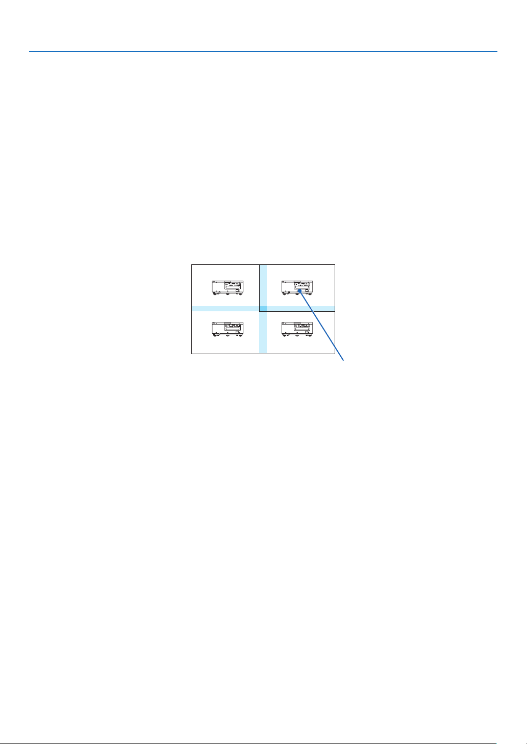
93
5. Using On-Screen Menu
Conditions for using tiling
• Alltheprojectorsneedtofullthefollowingconditions.
• Thepanelsizemustbethesame
• Theprojectionscreensizemustbethesame
• Theleftandrightendsortopandbottomendsoftheprojectionscreenmustbeconsistent.
• Thesettingsfortheleftandrightedgesoftheedgeblendingarethesame
• Thesettingsforthetopandbottomedgesoftheedgeblendingarethesame
Ifthetilingconditionsaresatised,thevideoscreenoftheprojectorateachinstallationpositionwillbeautomatically
extractedandprojected.
Ifthetilingconditionsarenotsatised,adjustthevideoscreenoftheprojectorateachinstallationpositionusing
thezoomfunction.
• AssignauniquecontrolIDtoeachprojector.
• Setthe“ColorSetting”and“DeepColorSetting”onyourBlu-rayplayerorcomputerto“Auto”.Refertotheowner’s
manualaccompanyingyourBlu-rayplayerorcomputerformoreinformation.
ConnecttheHDMIoutputofyourBlu-rayplayerorcomputertotherstprojector.ThenconnecttotheHDMIINinput
terminalofthesecondandsubsequenttiledprojectors.
Tilingsettingexample)Numberofhorizontalunits=2,Numberofverticalunits=2
Horizontalorder=Secondunit
Verticalorder=Firstunit
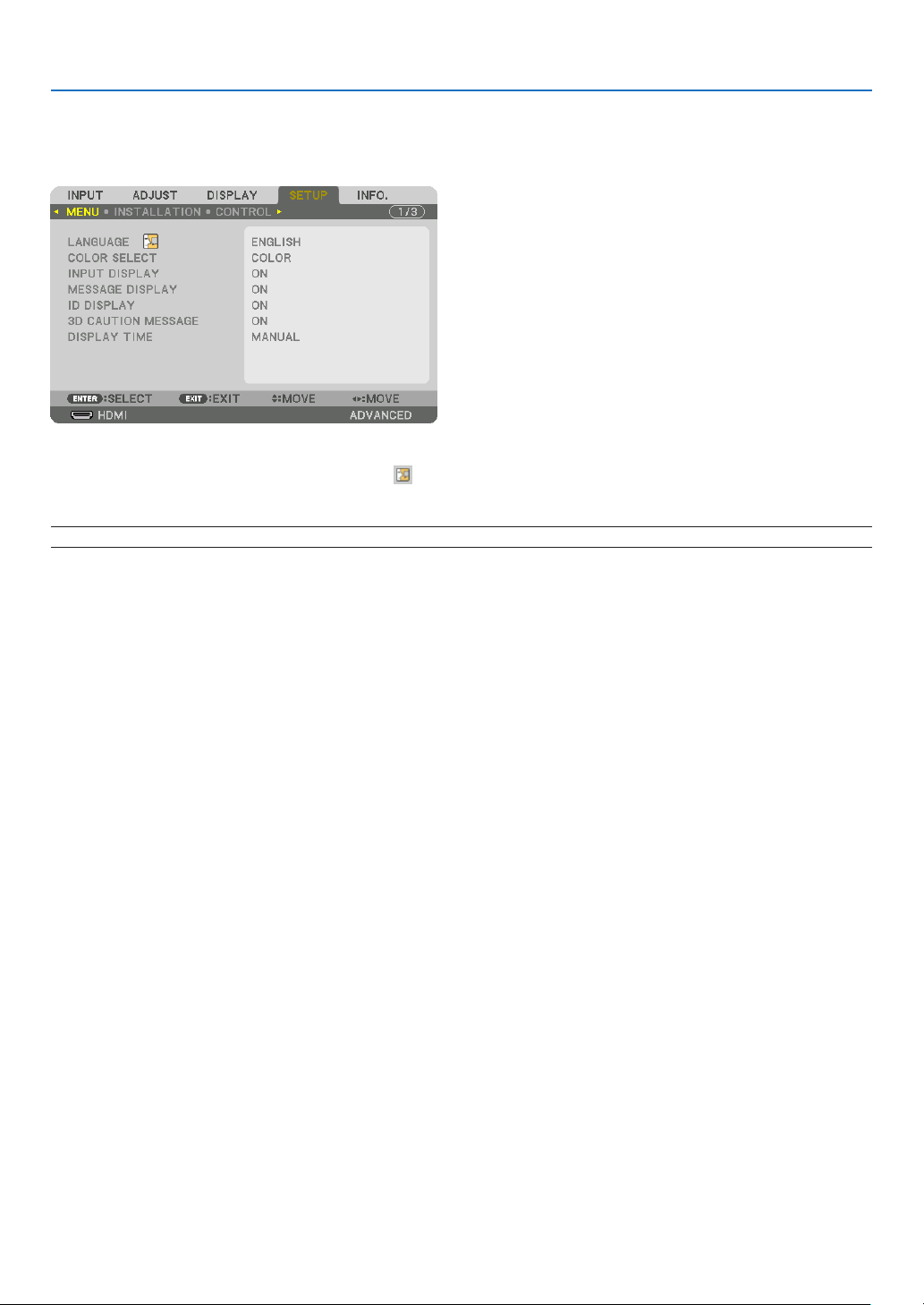
94
5. Using On-Screen Menu
❼ Menu Descriptions & Functions [SETUP]
[MENU]
SelectingMenuLanguage[LANGUAGE]
Youcanchooseoneof29languagesforon-screeninstructions.
NOTE:Yoursettingwillnotbeaffectedevenwhen[RESET]isdonefromthemenu.
SelectingMenuColor[COLORSELECT]
Youcanchoosebetweentwooptionsformenucolor:COLORandMONOCHROME.
TurningOn/OffSourceDisplay[INPUTDISPLAY]
ThisoptionturnsonoroffinputnamedisplaysuchasHDMI,DisplayPort,BNC,BNC(CV),BNC(Y/C),COMPUTER,
HDBaseTtobedisplayedonthetoprightofthescreen.
Turningmessagesonandoff[MESSAGEDISPLAY]
Thisoptionselectswhetherornottodisplayprojectormessagesatthebottomoftheprojectedimage.
Evenwhen“OFF”isselected,thesecuritylockwarningisdisplayed.Thesecuritylockwarningturnsoffwhenthe
securitylockiscanceled.
TurningON/OFFControlID[IDDISPLAY]
ID DISPLAY ����������� This option turns on or off the ID number which is displayed when the ID SET button on the remote control
is pressed� (→ page 105)

95
5. Using On-Screen Menu
[3DCAUTIONMESSAGE]
Thisselectswhethertodisplayacautionmessageornotwhenswitchingtoa3Dvideo.
ThedefaultconditionwhenshippedfromthefactoryisON.
OFF ������������������������ The 3D caution message screen will not be displayed�
ON ������������������������� The 3D caution message screen will be displayed when switching to a 3D video� Press the ENTER button
to cancel the message�
• Themessagewilldisappearautomaticallyafter60secondsorwhenotherbuttonsarepressed.Ifitdisap-
pears automatically, the 3D caution message will be displayed again when switching to a 3D video�
SelectingMenuDisplayTime[DISPLAYTIME]
Thisoptionallowsyoutoselecthowlongtheprojectorwaitsafterthelasttouchofabuttontoturnoffthemenu.The
presetchoicesare[MANUAL],[AUTO5SEC],[AUTO15SEC],and[AUTO45SEC].The[AUTO45SEC]isthefac-
torypreset.
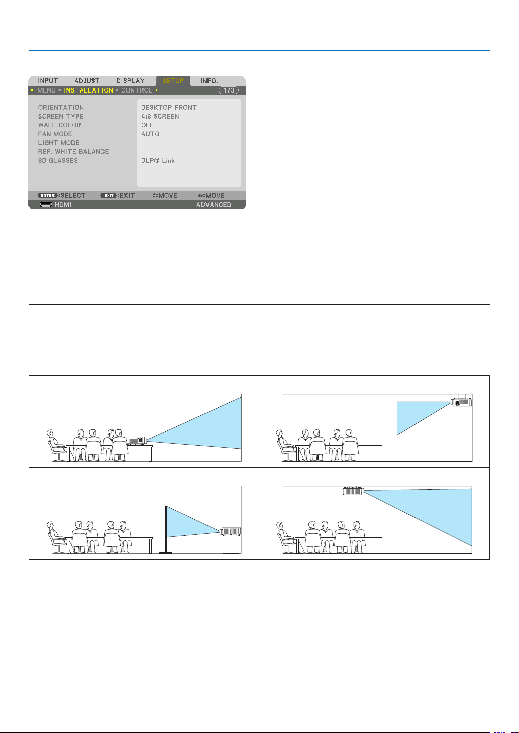
96
5. Using On-Screen Menu
[INSTALLATION]
SelectingProjectorOrientation[ORIENTATION]
Thisreorientsyourimageforyourtypeofprojection.Theoptionsare:desktopfrontprojection,ceilingrearprojection,
desktoprearprojection,andceilingfrontprojection.
NOTE:
• Pleaseconsultthedealerifyourequirespecialinstallationservicese.g.whenmountingtheprojectortoaceiling.Neverinstall
the projector on your own. This may result in the projector falling down and causing injury to people.
AUTO
��������������������� This automatically detects and projects the DESKTOP FRONT and CEILING FRONT�
NOTE:
• TheDESKTOPREARandCEILINGREARwillnotbedetected.Pleaseselectmanually.
DESKTOPFRONT CEILINGREAR
DESKTOPREAR CEILINGFRONT
TIP:
• CheckwhethertheautomaticDESKTOPFRONTisinstalledwithin±10degreesforoorinstallationandwhethertheCEILING
FRONTiswithin±10degreesforceilinginstallation.Selectmanuallywhentheprojectionscreenisinverted.
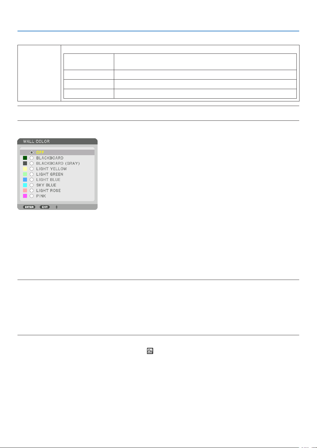
97
5. Using On-Screen Menu
SelectingAspectRatioandPositionforScreen[SCREENTYPE]
Screentype Setstheaspectratiooftheprojectionscreen.
FREE Theratiooftheliquidcrystalpanelisselected.Selectthiswhenprojecting
multi-screenand17:9screen(2K).
4:3screen Forascreenwitha4:3aspectratio
16:9screen Forascreenwitha16:9aspectratio
16:10screen Forascreenwitha16:10aspectratio
NOTE:
•
Afterchangingthescreentype,checkthesettingof[ASPECTRATIO]inthemenu.(→ page 80)
UsingtheWallColorCorrection[WALLCOLOR]
Thisfunctionallowsforquickadaptivecolorcorrectioninapplicationswherethescreenmaterialisnotwhite.
SelectingFanMode[FANMODE]
FanModeisusedtosetthespeedoftheinternalcoolingfan.
MODE �������������������� Select three modes for fan speed: AUTO and HIGH�
AUTO: The built-in fans automatically run at a variable speed according to the internal temperature�
HIGH: The built-in fans run at a high speed� Select this option when using the projector at altitudes ap-
proximately 2500 feet/760 meters or higher�
NOTE:
• Makesurethespeedissetto[HIGH]whenyouareusingthisdevicecontinuouslyforseveraldays.
• Set[FANMODE]to[HIGH]whenusingtheprojectorataltitudesapproximately2500feet/760metersorhigher.
• Usingtheprojectorataltitudesapproximately2500feet/760metersorhigherwithoutsettingto[HIGH]cancausetheprojector
tooverheatandtheprotectorcouldshutdown.Ifthishappens,waitacoupleminutesandturnontheprojector.
• Usingtheprojectorataltitudesapproximately2500feet/760metersorhighercanshortenthelifeofopticalcomponentssuchas
the light module.
• Yoursettingwillnotbeaffectedevenwhen[RESET]isdonefromthemenu.
TIP:
• When[HIGH]isselectedfor[FANMODE],asymbolicon will be displayed at the bottom of the menu.

98
5. Using On-Screen Menu
[LIGHTMODE]
Adjustingthe energysavingssettingsand thebrightnessof eachprojector inmulti-screen projection. Forenergy
savingssettings,seepage29“3-6.ChangingLIGHTMODE/CheckingEnergy-SavingEffectUsingLIGHTMODE
[LIGHTMODE]”.
LIGHTMODE NORMAL Thelightmoduleluminance(brightness)willbecome100%andthescreenwillturnbright.
ECO1 Bycontrollingthebrightnessandfanspeedaccordingtotheselectedsetting,energycan
besavedandmotionnoiseandthepowerconsumptioncanbelowered.
Canbeselectedwhen[CONSTANTBRIGHTNESS]modeissetto[OFF].
ECO2
CONSTANT
BRIGHTNESS
OFF [CONSTANTBRIGHTNESS]modewillbecanceled.
ON Maintainsthebrightnessthatisineffectatthetime[ON]isselected.Unless[OFF]isse-
lected,thesamesettingswillremainineffectevenwhentheprojectoristurnedoff.
• Tore-adjustthebrightness,rstturnthissettingOFFbeforemakingfurtheradjustments.
NOTE:
• [CONSTANTBRIGHTNESS]modeisafunctionusedtomaintainthebrightnessataconstant
level.Colorwillnotbexed.
ADJUST Brightnesscanbeadjustedin1%incrementsfrom20to100%.
Whenseveralprojectorsareusedformulti-screenprojection,thebrightnesscanbead-
justedindividuallyoneachprojector.
Theadjustmentiseffectivewhen[NORMAL][LIGHTMODE]isselectedand[CONSTANT
BRIGHTNESS]modeisturned[OFF].
TIP:
• Brightnessnormallydecreaseswithuse,butbyselecting[CONSTANTBRIGHTNESS]mode,sensorsinsidetheprojectordetect
brightness and automatically adjust the output, thereby maintaining a constant brightness throughout the life of the light module.
However,ifoutputisalreadyatitsmaximum,brightnesswilldecreasewithuse.
Forthisreason,whenusingmulti-screenprojection,itisrecommendedtoadjustthebrightnesstoaslightlylowerlevel,then
settingthe[CONSTANTBRIGHTNESS]modeto[ON].
[REF.WHITEBALANCE]
Thisfeatureallowsyoutoadjustthewhitebalanceforallsignals.
Thewhiteandblacklevelsofthesignalareadjustedforoptimumcolorreproduction.
CONTRAST R/CONTRAST G/CONTRAST B
������������������������������ These adjust the picture’s white color�
BRIGHTNESS R/BRIGHTNESS G/BRIGHTNESS B
������������������������������ These adjust the picture’s black color�
3D GLASSES
Select3Dglassesmethod.
DLP® Link ������������� Select when using DLP
®
Link type 3D glasses�
OTHERS ����������������� Select when using a non 3D emitter type glasses� It is required to connect the 3D emitter to the 3D SYNC
terminal of this projector� Please refer to page 40 about recommended items of 3D glasses and 3D emitter
for this projector�
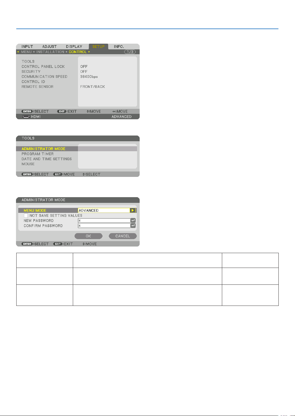
99
5. Using On-Screen Menu
[CONTROL]
TOOLS
ADMINISTRATORMODE
ThisallowsyoutoselectMENUMODE,savesettings,andsetapasswordfortheadministratormode.
MENUMODE Selecteither[BASIC]or[ADVANCED]menu.
(→page64)
—
NOTSAVESETTING
VALUES
Placing a check mark will not save your projector settings�
Clear this check box to save your projector settings�
—
NEWPASSWORD/
CONFIRMPASS-
WORD
Assignapasswordfortheadministratormode. Upto10alphanumeric
characters
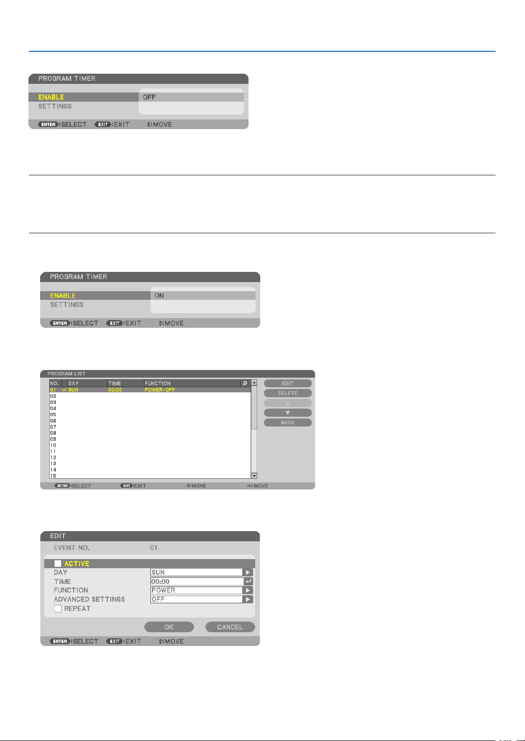
100
5. Using On-Screen Menu
PROGRAMTIMER
Thisoptionturns on/standbythe projectorand changesvideo signals,andselectsECO modeautomatically ata
speciedtime.
NOTE:
• Beforeusing[PROGRAMTIMER],makesurethatthe[DATEANDTIME]featureisset.(→ page 103)
MakesurethattheprojectorisinthestandbyconditionwiththePOWERcordconnected.
Theprojectorhasabuilt-inclock.Theclockwillkeepworkingforabouttwoweeksafterthemainpoweristurnedoff.Ifthemain
powerisnotsuppliedtotheprojectorfortwoweeksormore,itrequirestoset[DATEANDTIMESETTINGS]featureagain.
Setting a new program timer
1. On the PROGRAM TIMER screen, use the ▲ or ▼buttontoselect[SETTINGS]andpresstheENTERbutton.
The[PROGRAMLIST]screenwillbedisplayed.
2. Select a blank program number and press the ENTER button.
The[EDIT]screenwillbedisplayed.
3. Makesettingsforeachitemasrequired.
ACTIVE ������������������ Place a check mark to enable the program�
DAY ������������������������ Select days of the week for the program timer� To execute the program from Monday to Friday, select [MON-
FRI]� To execute the program in everyday basis, select [EVERYDAY]�
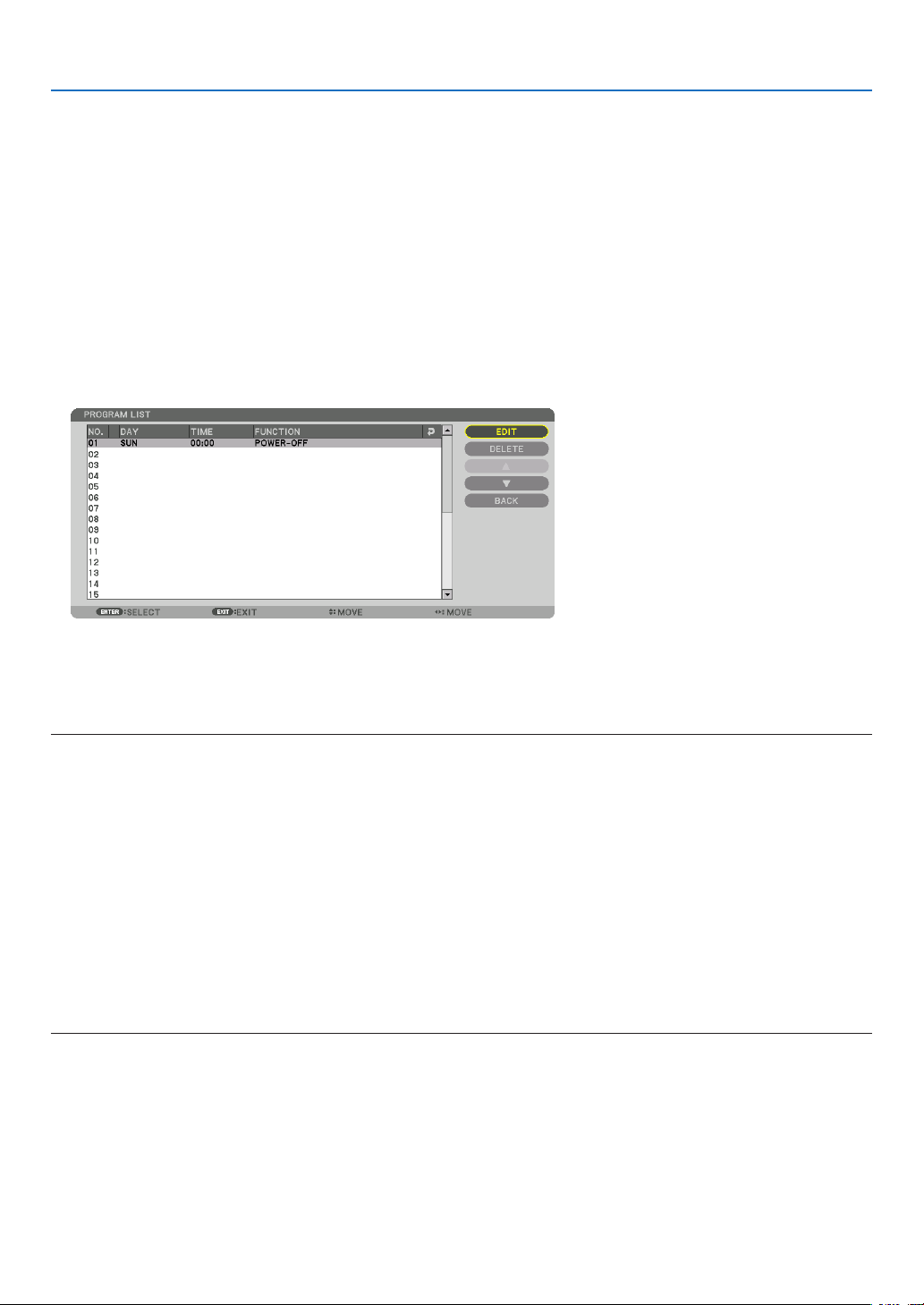
101
5. Using On-Screen Menu
TIME ���������������������� Set the time to execute the program� Enter time in 24-hour format�
FUNCTION ������������� Select a function to be executed� Selecting [POWER] will allow you to turn on or off the projector by setting
[ADVANCED SETTINGS]� Selecting [INPUT] will allow you to select a video source by setting [ADVANCED
SETTINGS]� Selecting [LIGHT MODE] will allow you to select [LIGHT MODE] by setting [ADVANCED SET-
TINGS]�
ADVANCED SETTINGS
������������������������������ Select power on/off, a type of video source, or LIGHT MODE for the selected item in [FUNCTION]�
REPEAT ������������������ Place a check mark to repeat the program continuing basis� To use the program this week only, clear the
check mark�
4. Select[OK]andpresstheENTERbutton.
Thiswillcompletethesettings.
Youwillbereturnedtothe[PROGRAMLIST]screen.
5. Select[BACK]andpresstheENTERbutton.
Youwillbereturnedtothe[PROGRAMTIMER]screen.
6. Select[OK]andpresstheENTERbutton.
Youwillbereturnedtothe[TOOLS]screen.
NOTE:
• Upto30differenttimersettingscanbeprogrammed.
• When[PROGRAMTIMER]isturnedon,the[STANDBYMODE]settingisignored.
• TheProgramTimerisexecutedonasettimebasis,notinaprogrambasis.
• Oncetheprogramnotmarkedwithacheckin[REPEAT]hasbeenexecuted,thecheckmarkinthe[ACTIVE]checkboxwillbe
cleared automatically and the program will be disabled.
• Whentheon-timeandtheoff-timesetforthesametime,theoff-timesettingwilltakepreference.
• Twodifferentsourcesaresetforthesametime,thelargerprogramnumberwilltakepreference.
• Theon-timesettingwillnotbeexecutedwhilethecoolingfansarerunningoranerrorisoccurring.
• Iftheoff-timesettingisexpiredundertheconditioninwhichthepoweroffisnotpossible,theoff-timersettingwillnotbeexecuted
until the power off becomes possible.
• Programsnotmarkedwithacheckmarkin[ACTIVE]ofthe[EDIT]screenwillnotbeexecutedeveniftheProgramTimeris
enabled.
• Whentheprojectoristurnedonbyusingtheprogramtimerandifyouwanttoturnofftheprojector,settheoff-timeordoit
manually so as not to leave the projector on for a long period of time.

102
5. Using On-Screen Menu
Activating the program timer
1. Select[ENABLE]onthe[PROGRAMTIMER]screenandpresstheENTERbutton.
Theselectionscreenwillbedisplayed.
2. Press the ▼buttontoalignthecursorwith[ON]andthenpresstheENTERbutton.
Returntothe[PROGRAMTIMER]screen.
NOTE:
• Whentheeffectivesettingsofthe[PROGRAMTIMER]havenotbeensetto[ON],theprogramwillnotbeexecutedevenifthe
[ACTIVE]itemsintheprogramlisthavebeenticked.
• Evenwhentheeffectivesettingsofthe[PROGRAMTIMER]aresetto[ON],the[PROGRAMTIMER]willnotworkuntilthe[PRO-
GRAMTIMER]screenisclosed.
Changing the programmed settings
1. Onthe[PROGRAMLIST]screen,selectaprogramyouwanttoeditandpresstheENTERbutton.
2. Changethesettingsonthe[EDIT]screen.
3. Select[OK]andpresstheENTERbutton.
Theprogrammedsettingswillbechanged.
Youwillbereturnedtothe[PROGRAMLIST]screen.
Changing the order of programs
1. Onthe[PROGRAMLIST]screen,selectaprogramwhoseorderyouwanttochangeandpressthe▶ button.
2. Press the ▼ button to select ▲ or ▼.
3. PresstheENTERbuttonafewtimestoselectarowtowhichyouwishtomovetheprogram.
Theorderoftheprogramswillbechanged.
Deleting the programs
1. Onthe[PROGRAMLIST]screen,selectaprogramnumberyouwanttodeleteandpressthe▶ button.
2. Press the ▼buttontoselect[DELETE].
3. Press the ENTER button.
Theconrmationscreenwillbedisplayed.
4. Select[YES]andpresstheENTERbutton.
Theprogramwillbedeleted.
Thiswillcompletedeletingtheprogram.

103
5. Using On-Screen Menu
DATEANDTIMESETTINGS
Youcansetthecurrenttime,month,date,andyear.
NOTE:Theprojectorhasabuilt-inclock.Theclockwillkeepworkingforabout2weeksafterthemainpoweristurnedoff.Ifthe
mainpowerisofffor2weeksormore,thebuilt-inclockwillcease.Ifthebuilt-inclockceases,setthedateandtimeagain.The
built-in clock will not cease while in the standby mode.
TIME ZONE SETTINGS
�������������� Select your time zone�
DATE AND TIME SETTINGS ������ Set your current date (MM/DD/YYYY) and time (HH:MM)�
INTERNET TIME SERVER ��������� If you place a check mark, the projector’s built-in clock will be synchronized with an Internet
time server in every 24 hours and at the time of projector’s startup�
UPDATE ������������������������������������ Synchronizes the projector’s built-in clock immediately� The UPDATE button is not available
unless the INTERNET TIME SERVER check box is turned on�
SUMMER TIME SETTINGS ������� If you place a check mark, the clock for daylight saving will be enabled�
[MOUSE]
Thisfunctioncannotbeusedinthisdevice.Itisusedforfutureexpansionpurposesonly.

104
5. Using On-Screen Menu
DisablingtheCabinetButtons[CONTROLPANELLOCK]
ThisoptionturnsonorofftheCONTROLPANELLOCKfunction.
NOTE:
• Howtocancelthe[CONTROLPANELLOCK]
Whenthe[CONTROLPANELLOCK]issetto[ON],presstheSOURCEbuttononthemainbodyforabout10secondstocancel
the[CONTROLPANELLOCK].
TIP:
• Whenthe[CONTROLPANELLOCK]isturnedon,akeylockicon[ ]willbedisplayedatthebottomrightofthemenu.
• ThisCONTROLPANELLOCKdoesnotaffecttheremotecontrolfunctions.
EnablingSecurity[SECURITY]
ThisfeatureturnsonorofftheSECURITYfunction.
Unlessthecorrectkeywordisentered,theprojectorcannotprojectanimage.(→page35)
NOTE:Yoursettingwillnotbeaffectedevenwhen[RESET]isdonefromthemenu.
SelectingCommunicationSpeed[COMMUNICATIONSPEED]
ThisfeaturesetsthebaudrateofthePCControlport(D-Sub9P).Itsupportsdataratesfrom4800to115200bps.
Thedefaultis38400bps.Selecttheappropriatebaudrateforyourequipmenttobeconnected(dependingonthe
equipment,alowerbaudratemayberecommendedforlongcableruns).
NOTE:
• Select[38400bps]orlesswhenusingthesuppliedsoftwareprograms.
• Yourselectedcommunicationspeedwillnotbeaffectedevenwhen[RESET]isdonefromthemenu.
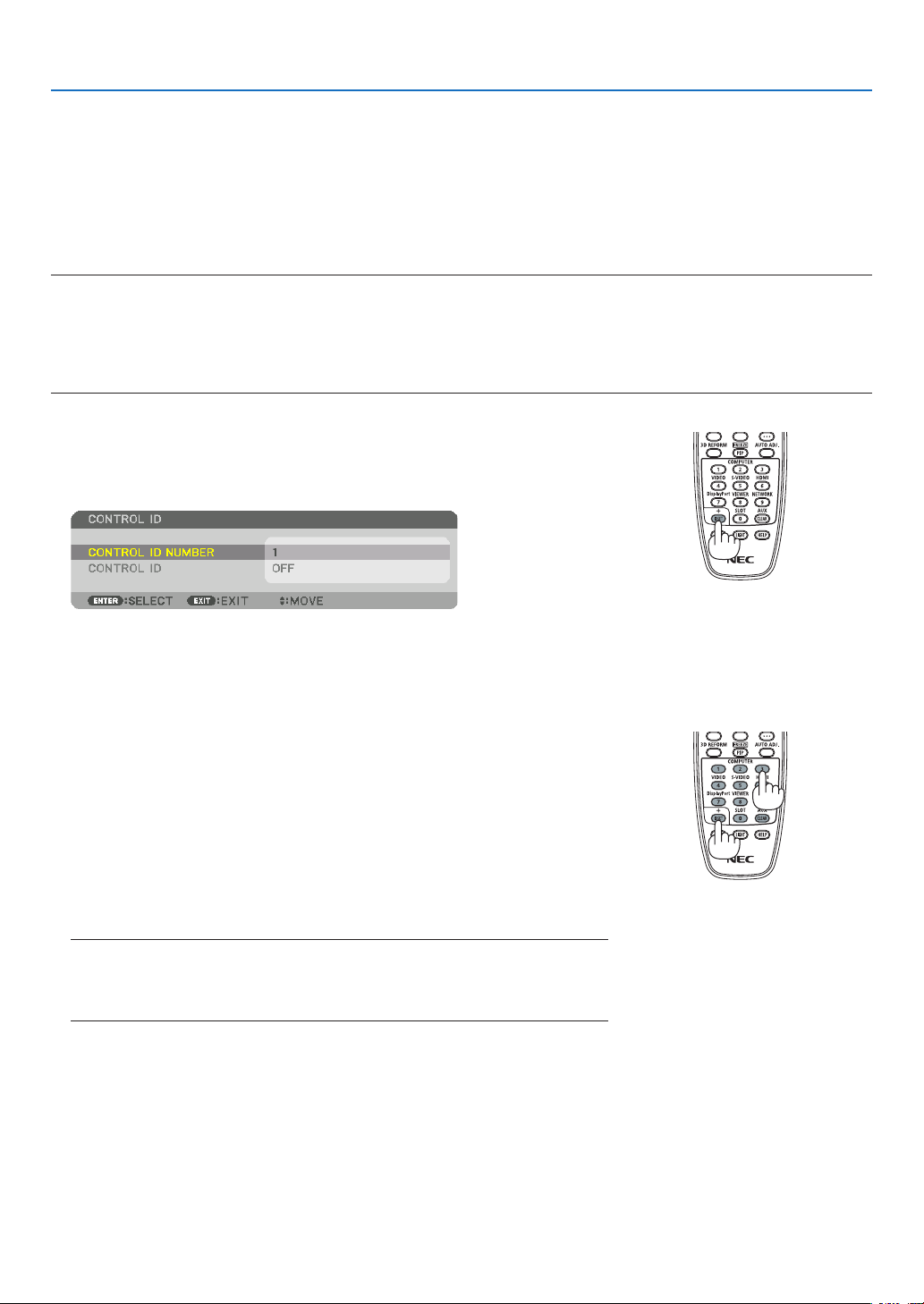
105
5. Using On-Screen Menu
SettingIDtotheProjector[CONTROLID]
YoucanoperatemultipleprojectorsseparatelyandindependentlywiththesingleremotecontrolthathastheCONTROL
IDfunction.IfyouassignthesameIDtoalltheprojectors,youcanconvenientlyoperatealltheprojectorstogether
usingthesingleremotecontrol.Todoso,youhavetoassignanIDnumbertoeachprojector.
CONTROL ID NUMBER ������� Select a number from 1 to 254 you wish to assign to your projector�
CONTROL ID �����������������������Select [OFF] to turn off the CONTROL ID setting and select [ON] to turn on the CONTROL ID setting�
NOTE:
• When[ON]isselectedfor[CONTROLID],theprojectorcannotbeoperatedbyusingtheremotecontrolthatdoesnotsupport
theCONTROLIDfunction.(Inthiscasethebuttonsontheprojectorcabinetcanbeused.)
• Yoursettingwillnotbeaffectedevenwhen[RESET]isdonefromthemenu.
• PressingandholdingtheENTERbuttonontheprojectorcabinetfor10secondswilldisplaythemenuforcancelingtheControl
ID.
Assigning or Changing the Control ID
1. Turn on the projector.
2. Press the ID SET button on the remote control.
TheCONTROLIDscreenwillbedisplayed.
IftheprojectorcanbeoperatedwiththecurrentremotecontrolID,the[AC-
TIVE]willbedisplayed.Iftheprojectorcannotbeoperatedwiththecurrent
remotecontrolID,the[INACTIVE]willbedisplayed.Tooperatetheinactive
projector,assignthecontrolIDusedfortheprojectorbyusingthefollowing
procedure(Step3).
3. PressoneofnumerickeypadbuttonswhilepressingandholdingtheID
SET button on the remote control.
Example:
Toassign“3”,pressthe“3”buttonontheremotecontrol.
NoIDmeansthatalltheprojectorscanbeoperatedtogetherwithasingle
remotecontrol.Toset“NoID”,enter“000”orpresstheCLEARbutton.
TIP:TherangeofIDsisfrom1to254.
4. Release the ID SET button.
TheupdatedCONTROLIDscreenwillbedisplayed.
NOTE:
• TheIDscanbeclearedinafewdaysafterthebatteriesarerundownorremoved.
• Ifoneofbuttons oftheremotecontrol withoutbatteriesispressedaccidentally,
currentspeciedIDwillbecleared.

106
5. Using On-Screen Menu
TurningOnorOffRemoteSensor[REMOTESENSOR]
Thisoptiondetermineswhichremotesensorontheprojectorisenabledinwirelessmode.
Theoptionsare:FRONT/BACK,FRONT,BACK,andHDBaseT.
NOTE:
• TheremotecontroloftheprojectorwillnotbeabletoreceivesignalsifthepowersupplyoftheHDBaseTtransmissiondevice
connectedtotheprojectorisswitchedonwhenthishasbeensetto“HDBaseT”.
TIP:
• Iftheremotecontrolsystemdoesnotfunctionwhendirectsunlightorstrongilluminationstrikestheremotecontrolsensorof
the projector, change another option.

107
5. Using On-Screen Menu
[NETWORK SETTINGS]
Important:
• Consultwithyournetworkadministratoraboutthesesettings.
• WhenusingawiredLANconnection,connectaLANcable(Ethernetcable)totheLANport(RJ-45)oftheprojector.(→ page
133
)
TIP:Thenetworksettingsyoumakewillnotbeaffectedevenwhen[RESET]isdonefromthemenu.
Hints on How to Set Up LAN Connection
To set up the projector for a LAN connection:
Select[WIREDLAN]→[PROFILES]→[PROFILE1]or[PROFILE2].
TwosettingscanbesetforwiredLAN.
Nextturnonorofffor[DHCP],[IPADDRESS],[SUBNETMASK],and[GATEWAY]andselect[OK]andpressthe
ENTERbutton.(→page108)
To recall LAN settings stored in the profile number:
Select[PROFILE1]or[PROFILE2]forwiredLAN,andthenselect[OK]andpresstheENTERbutton.(→page108)
ToconnectaDHCPserver:
Turnon[DHCP]forwiredLAN.Select[ON]andpresstheENTERbutton.TospecifyIPaddresswithoutusingthe
DHCPserver,turnoff[DHCP].(→page108)
Toreceiveerrormessagesviae-mail:
Select[ALERTMAIL],andset[SENDER'SADDRESS],[SMTPSERVERNAME],and[RECIPIENT'SADDRESS].
Last,select[OK]andpresstheENTERbutton.(→page110)

108
5. Using On-Screen Menu
WIRED LAN
PROFILES • Thesettingsforusingthebuilt-inEthernet/HDBaseTportinthe
projectorcanberecordedintheprojectormemoryintwoways.
• Select[PROFILE1]or[PROFILE2]andthendosettingsfor
[DHCP]andtheotheroptions.
Afterdoingthis,select[OK]andpresstheENTERbutton.This
willstoreyoursettingsinmemory.
• Torecallthesettingsfrommemory:
Afterselecting[PROFILE1]or[PROFILE2]fromthe[PRO-
FILES]list.
Select[OK]andpresstheENTERbutton.
• Select[DISABLE]whennotconnectingtoawiredLAN
—
DHCP
PlaceacheckmarktoautomaticallyassignanIPaddresstothe
projectorfromyourDHCPserver.
ClearthischeckboxtoregistertheIPaddressorsubnetmask
numberobtainedfromyournetworkadministrator.
—
IPADDRESS SetyourIPaddressofthenetworkconnectedtotheprojector
when[DHCP]isturnedoff.
Upto12numeric
characters
SUBNETMASK Setyoursubnetmasknumberofthenetworkconnectedtothe
projectorwhen[DHCP]isturnedoff.
Upto12numeric
characters
GATEWAY
Setthedefaultgatewayofthenetworkconnectedtotheprojector
when[DHCP]isturnedoff.
Upto12numeric
characters
AUTODNS PlaceacheckmarktoautomaticallyassigntheIPaddressofyour
DNSserverconnectedtotheprojectorfromyourDHCPserver.
ClearthischeckboxtosettheIPaddressofyourDNSserver
connectedtotheprojector.
Upto12numeric
characters
DNSCONFIGURA-
TION
SettheIPaddressofyourDNSserveronthenetworkconnected
totheprojectorwhen[AUTODNS]iscleared.
Upto12numeric
characters
RECONNECT
Retrytoconnecttheprojectortoanetwork.Trythisifyouhave
changed[PROFILES].
—
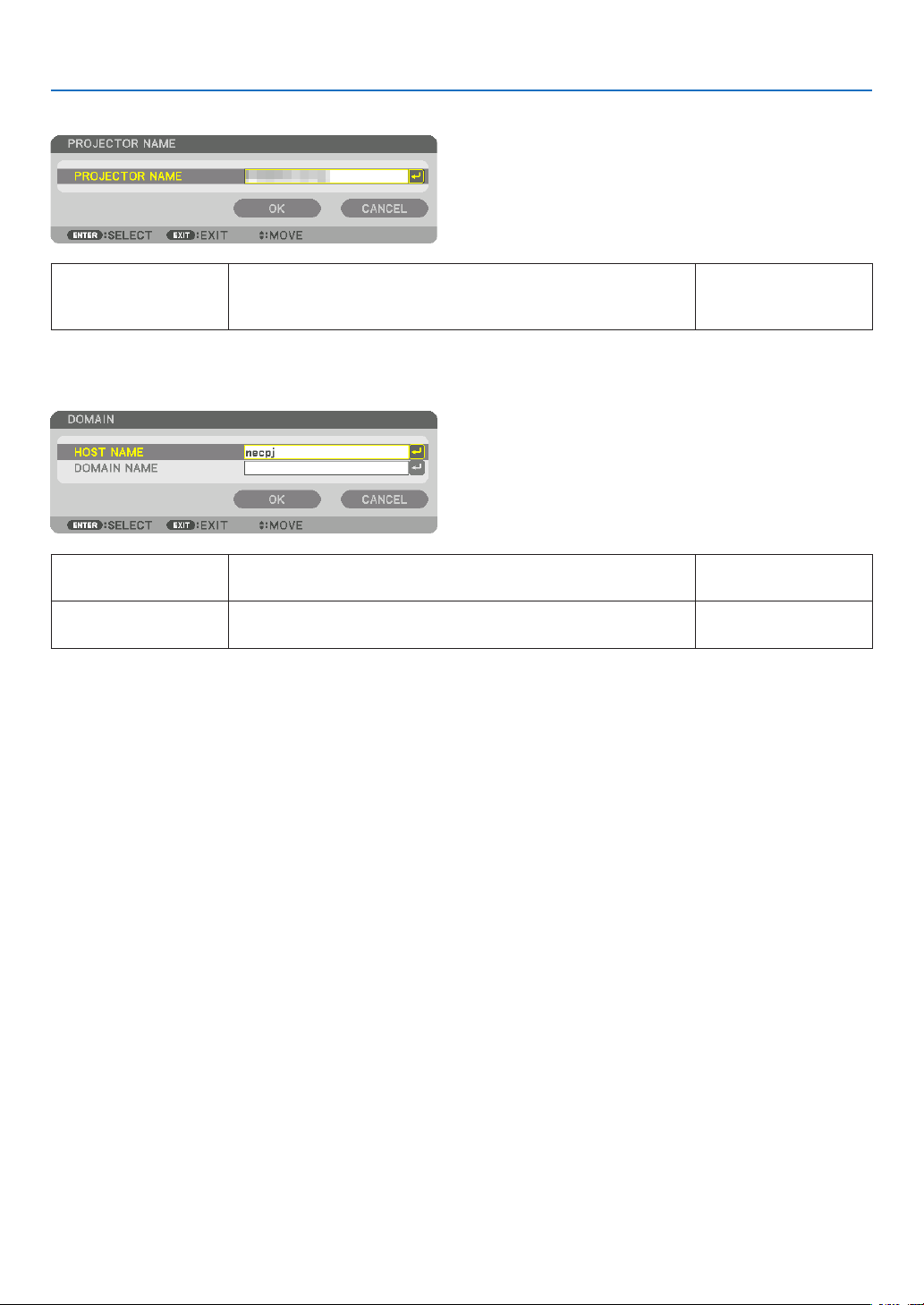
109
5. Using On-Screen Menu
PROJECTORNAME
PROJECTORNAME Setauniqueprojectorname. Upto16alphanu-
mericcharactersand
symbols
DOMAIN
Setahostnameanddomainnameoftheprojector.
HOSTNAME Setahostnameoftheprojector. Upto15alphanumeric
characters
DOMAINNAME Setadomainnameoftheprojector. Upto60alphanumeric
characters
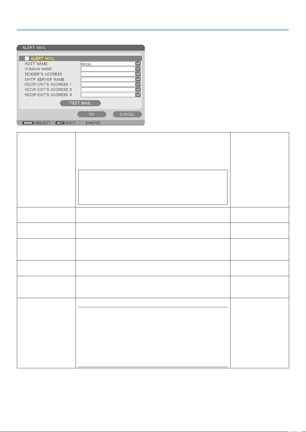
110
5. Using On-Screen Menu
ALERTMAIL
ALERTMAIL Thisoptionwillnotifyyourcomputeroferrormessagesviae-mail
whenusingwirelessorwiredLAN.
Placing a checkmark will turn on the Alert Mail feature�
Clearing a checkmark will turn off the Alert Mail feature�
Sample of a message to be sent from the projector:
Subject:[Projector]ProjectorInformation
THECOOLINGFANHASSTOPPED.
[INFORMATION]
PROJECTORNAME:PX602ULSeries
LIGHTHOURSUSED:0000[H]
—
HOSTNAME Typeinahostname. Upto15alphanumeric
characters
DOMAINNAME Typeinadomainnameofthenetworkconnectedtotheprojector. Upto60alphanumeric
characters
SENDER'SAD-
DRESS
Specifythesender’saddress. Upto60alphanu-
mericcharactersand
symbols
SMTPSERVER
NAME
TypeintheSMTPservernametobeconnectedtotheprojector. Upto60alphanumeric
characters
RECIPIENT'SAD-
DRESS1,2,3
Typeinyourrecipient’saddress. Upto60alphanu-
mericcharactersand
symbols
TESTMAIL Sendatestmailtocheckifyoursettingsarecorrect.
NOTE:
• Ifyouenteredanincorrectaddressinatest,youmaynotreceivean
Alert mail. Should this happen, check if the Recipient’s Address is
correctly set.
• Unlessany one of the [SENDER'S ADDRESS], [SMTP SERVER'S
NAME]or[RECIPIENT'SADDRESS1-3]isselected,[TESTMAIL]is
not available.
• Besuretohighlight[OK]andpresstheENTERbuttonbeforeexecuting
[TESTMAIL].
—

111
5. Using On-Screen Menu
NETWORKSERVICE
HTTPSERVER SetapasswordforyourHTTPserver. Upto10alphanumeric
characters
PJLink
This option allows you to set a passwordwhen you use the
PJLinkfeature.
NOTE:
• Donotforgetyourpassword.However,ifyouforgetyourpassword,
consult with your dealer.
• WhatisPJLink?
PJLinkisastandardizationofprotocolusedforcontrollingprojectors
of different manufacturers. This standard protocol is established by
JapanBusinessMachineandInformationSystemIndustriesAssocia-
tion(JBMIA)in2005.
TheprojectorsupportsallthecommandsofPJLinkClass1.
• SettingofPJLinkwillnotbeaffectedevenwhen[RESET]isdonefrom
the menu.
Upto32alphanumeric
characters
AMXBEACON Turnon orofffordetectionfromAMX DeviceDiscoverywhen
connectingtothenetworksupportedbyAMX’sNetLinxcontrol
system.
TIP:
WhenusingadevicethatsupportsAMXDeviceDiscovery,allAMXNetLinx
control system will recognize the device and download the appropriate
DeviceDiscoveryModulefromanAMXserver.
Placing a checkmark will enable detecting the projector from AMX Device
Discovery�
Clearing a checkmark will disable detecting the projector from AMX
Device Discovery�
—
CRESTRON
ROOMVIEW:Turnonoroffwhencontrollingtheprojectorfrom
yourPC.
CRESTRON CONTROL:Turn on or off when controlling the
projectorfromyourcontroller.
• CONTROLLERIPADDRESS:EnteryourIPaddressofCREST-
RONSERVER.
• IPID:EnteryourIPIDofCRESTRONSERVER.
Upto12numeric
characters
TIP:TheCRESTRONsettingsarerequiredonlyforusewithCRESTRONROOMVIEW.
Formoreinformation,visithttp://www.crestron.com

112
5. Using On-Screen Menu
[SOURCE OPTIONS]
SettingAutoAdjust[AUTOADJUST]
ThisfeaturesetstheAutoAdjustmodesothatthecomputersignalcanbeautomaticallyormanuallyadjustedfor
noiseandstability.Youcanautomaticallymakeadjustmentintwoways:[NORMAL]and[FINE].
OFF ������������������������ The computer signal will not be automatically adjusted� You can manually optimize the computer signal�
NORMAL ���������������� Default setting� The computer signal will be automatically adjusted� Normally select this option�
FINE ����������������������� Select this option if fine adjustment is needed� It takes more time to switch to the source than when [NOR-
MAL]is selected�
TIP:
• Thedefaultsettingwhenshippedfromthefactoryis[NORMAL].
• WhentheAUTOADJ.buttonispressed,thesame[FINE]adjustmentiscarriedout.
[COLORSYSTEM]
ThisfeatureallowsyoutoselecttheTVvideosignal,whichdiffersfromcountrytocountry(NTSC,PAL,etc.).
Thisissetto[AUTO]byfactorydefault.Setthisiftheprojectorcannotidentifythesignalautomatically.
SelectingDefaultSource[DEFAULTINPUTSELECT]
Youcansettheprojectortodefaulttoanyoneofitsinputseachtimetheprojectoristurnedon.
LAST ���������������������� Set the projector to default to the previous or last active input each time the projector is turned on�
AUTO ��������������������� Search for an active source in order of HDMI → DisplayPort → BNC → BNC(CV) → BNC(Y/C) → COMPUTER
→ HDBaseT → SLOT and displays the first found source�
HDMI ��������������������� Display the digital source from the HDMI IN terminal every time the projector is turned on�
DisplayPort ������������ Display the digital source from the DisplayPort IN terminal every time the projector is turned on�
BNC ����������������������� Project the input signal from the BNC input terminal
BNC(CV)
���������������� Project the input signal from the BNC(CV) input terminal�
BNC(Y/C) ��������������� Project the input signal from the BNC(Y/C) input terminal�
COMPUTER ����������� Display the computer signal from the COMPUTER 1 IN terminal every time the projector is turned on�
HDBaseT ���������������� Project the HDBaseT or WIRED LAN signal�
SLOT ���������������������� Project the picture via the optional board (sold separately) inserted into the SLOT�

113
5. Using On-Screen Menu
SettingClosedCaption[CLOSEDCAPTION]
ThisoptionsetsseveralclosedcaptionmodesthatallowtexttobesuperimposedontheprojectedimageofVideo
orS-Video.
Thesubtitlesandtextwillbedisplayedashortwhileaftertheon-screenmenudisappears.
OFF ������������������������ This exits the closed caption mode�
CAPTION 1-4 ��������� Text is superimposed�
TEXT 1-4 ���������������� Text is displayed�
SelectingaColororLogoforBackground[BACKGROUND]
Usethisfeaturetodisplayablue/blackscreenorlogowhennosignalisavailable.Thedefaultbackgroundis[BLUE].
NOTE:
• Evenwhenthebackgroundlogoisselected,iftwopicturesaredisplayedin[PIP/PICTUREBYPICTURE]mode,thebluebackground
is displayed without the logo when there is no signal.

114
5. Using On-Screen Menu
[POWER OPTIONS]
SelectingPower-savingin[STANDBYMODE]
Settingthepowerconsumptioninthestandbymode.
NORMAL ���������������� In the standby mode, the power consumption of the projector is 0�5 W�
In the standby mode, the POWER indicator lights up in red while the STATUS indicator will go off�
• Whensetto[NORMAL],thefollowingterminalsandfunctionswillbedisabled.HDMIOUTterminals,
Ethernet/HDBaseT port, LAN function, mail notification function
NETWORK STANDBY
������������������������������ Compared to [NORMAL], the power consumption in the standby mode is higher but power can be supplied
to the projector using a wired LAN�
In the standby mode, the power indicator will light up in orange while the status indicator will be turned off�
Important:
• When[NETWORKSTANDBY]isselected,[AUTOPOWEROFF]willturngreyincolorandbedisabledand[0:15]willbeselected
automatically.
• Inthefollowingconditions,the[STANDBYMODE]settingwillbedisabledandtheprojectorwillgointothesleepmode.Inthe
sleep mode, the fans in the projector rotate for the purpose of interior parts protection.
* Sleepmodereferstothemodewherebythefunctionalrestrictionsduetothe[STANDBYMODE]settingareremoved.
• When[ENABLE]isselectedunder[NETWORKSERVICE]→[AMXBEACON]
• When[HDBaseT]isselectedunder[CONTROL]→[REMOTESENSOR]
• WhenasignalisbeingreceivedfromaHDBaseTtransmissiondevice
• When[NORMAL]isselected,the[AUTOPOWERONSELECT]displayturnsgreyincolorandisdisabled,and[OFF]isautomati-
cally selected.
NOTE:
• WhenconnectingtoaHDBaseTtransmissiondevicesoldcommercially,ifthetransmissiondeviceissettotransmitremotecontrol
signals, the power consumption of the projector in the standby mode will increase.
TIP:
• Yoursettingwillnotbeaffectedevenwhen[RESET]isdonefromthemenu.
• ThepowerconsumptioninthestandbymodewillnotbeincludedincalculatingCO
2
emission reduction.
EnablingDirectPowerOn[DIRECTPOWERON]
Turnstheprojectoronautomaticallywhenthepowercordisinsertedintoanactivepoweroutlet.Thiseliminatesthe
needtoalwaysusethePOWERbuttonontheremotecontrolorprojectorcabinet.

115
5. Using On-Screen Menu
TurningOntheProjectorByApplyingComputerSignal[AUTOPOWERONSELECT]
Ifsetto[NETWORKSTANDBY],theprojectorautomaticallydetectsthesynchronizingsignalinputfromthefollowing
selectedterminalsandprojectsthepictureaccordingly:Computer,HDMI,DisplayPort,HDBaseT,andSLOT.
OFF ������������������������ AUTO POWER ON SELECT function will be switch off�
HDMI, DisplayPort, COMPUTER, HDBaseT, SLOT
������������������������������ When a computer signal of a selected input terminal is detected, the power supply of the projector will be
turned on automatically and the computer screen will be projected�
NOTE:
• IfyouwanttoactivatetheAUTOPOWERONSELECTfunctionafterpoweringOFFtheprojector,interruptthesignalfromtheinput
terminals or disconnect the computer cable from the projector and wait for at least 3 seconds before inputting the signal from
theselectedterminal.WhentheprojectoristurnedoffandentersNETWORKSTANDBYmode,butsignalsfromthecomputer
continuetobesenttheprojector,theprojectormaintainsNETWORKSTANDBYmodeandwillnotturnONautomatically.Inaddi-
tion,ifsignalsfromHDMI,DisplayPortorHDBaseTcontinuetobesenttotheprojector,dependingonthesettingsofconnected
externaldevices,theprojectormayturnONautomaticallyevenifitispoweredoffandNETWORKSTANDBYmodeisineffect.
• ThisfunctiondoesnotworkwhencomponentsignalscomeintoCOMPUTER1INterminalorwhencomputersignalsareSync
onGreenorCompositeSync.
EnablingPowerManagement[AUTOPOWEROFF]
Whenthisoptionisselectedyoucanenabletheprojectortoautomaticallyturnoff(attheselectedtime:0:05,0:10,
0:15,0:20,0:30,1:00)ifthereisnosignalreceivedbyanyinputorifnooperationisperformed.
NOTE:
• ThepowerwillnotgooffautomaticallywhenasignalfromtheEthernet/HDBaseTportisbeingprojected.
• [AUTOPOWEROFF]appearsingreywhenthe[STANDBYMODE]issetto[NETWORKSTANDBY]and[0:15]willbesetautomati-
cally.
UsingOffTimer[OFFTIMER]
1. Select your desired time between 30 minutes and 16 hours: OFF, 0:30, 1:00, 2:00, 4:00, 8:00, 12:00, 16:00.
2. Press the ENTER button on the remote control.
3. The remaining time starts counting down.
4. Theprojectorwillturnoffafterthecountdowniscomplete.
NOTE:
• Tocancelthepresettime,set[OFF]forthepresettimeorturnoffthepower.
• Whentheremainingtimereaches3minutesbeforetheprojectoristurnedoff,the[THEPROJECTORWILLTURNOFFWITHIN3
MINUTES]messagewillbedisplayedonthebottomofthescreen.
SettingfortheOptionalBoard[SLOTPOWER]
Whenusingtheoptionalboardinstalledintheslot,setthefollowingoptions.
PROJECTOR ON �����������������Thisfeaturewillturnonoroffthepowertotheoptionalboard.
OFF: Forcibly turn off the power to the optional board installed in the slot�
ON (Default): Turn on the power to the optional board installed in the slot�
PROJECTOR STANDBY �������Thisfeaturewillautomaticallyenableordisabletheoptionalboardinstalledintheslot
whentheprojectorisinstandby.
DISABLE: Select this option to disable the optional board in the projector standby�
ENABLE (Default): Select this option to enable the optional board in the projector standby�
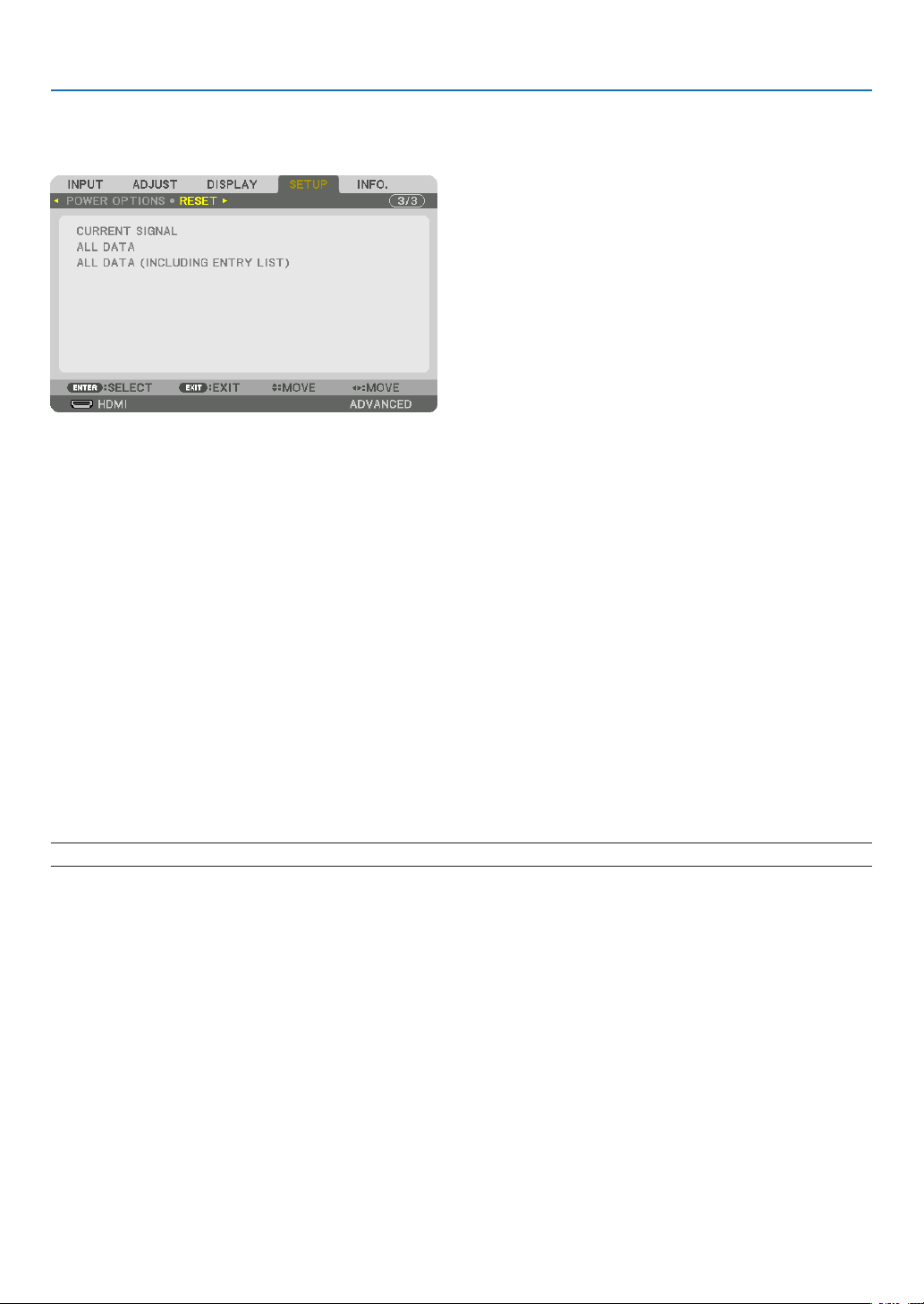
116
5. Using On-Screen Menu
Returning to Factory Default [RESET]
TheRESETfeatureallowsyoutochangeadjustmentsandsettingstothefactorypresetfora(all)source(s)except
thefollowing:
[CURRENTSIGNAL]
Resetstheadjustmentsforthecurrentsignaltothefactorypresetlevels.
Theitemsthatcanberesetare:[PRESET],[CONTRAST],[BRIGHTNESS],[COLOR],[HUE],[SHARPNESS],[AS-
PECTRATIO],[HORIZONTAL],[VERTICAL],[CLOCK],[PHASE],and[OVERSCAN].
[ALLDATA]
Resetalltheadjustmentsandsettingsforallthesignalstothefactorypreset.
AllitemscanberesetEXCEPT[LANGUAGE],[BACKGROUND],[FILTERMESSAGE],[EDGEBLENDING],[MULTI
SCREEN],[SCREENTYPE],[GEOMETRICCORRECTION],[REF.WHITEBALANCE],[ADMINISTRATORMODE],
[CONTROLPANELLOCK],[SECURITY],[COMMUNICATIONSPEED],[CONTROLID],[STANDBYMODE],[FAN
MODE],[LIGHTHOURSUSED],[TOTALCARBONSAVINGS],and[WIREDLAN].
[ALLDATA(INCLUDINGENTRYLIST)]
Resetalltheadjustmentsandsettingsforallthesignalstothefactorypresetexcept[LANGUAGE],[BACKGROUND],
[FILTER MESSAGE], [EDGE BLENDING], [MULTI SCREEN], [SCREENTYPE], [GEOMETRIC CORRECTION],
[REF.WHITEBALANCE],[ADMINISTRATORMODE],[CONTROLPANELLOCK],[SECURITY],[COMMUNICATION
SPEED],[CONTROLID],[STANDBYMODE],[FANMODE],[LIGHTHOURSUSED],[TOTALCARBONSAVINGS],
and[WIREDLAN].
Alsodeletesallthesignalsinthe[ENTRYLIST]andreturnstothefactorypreset.
NOTE:LockedsignalsinEntryListcannotbereset.
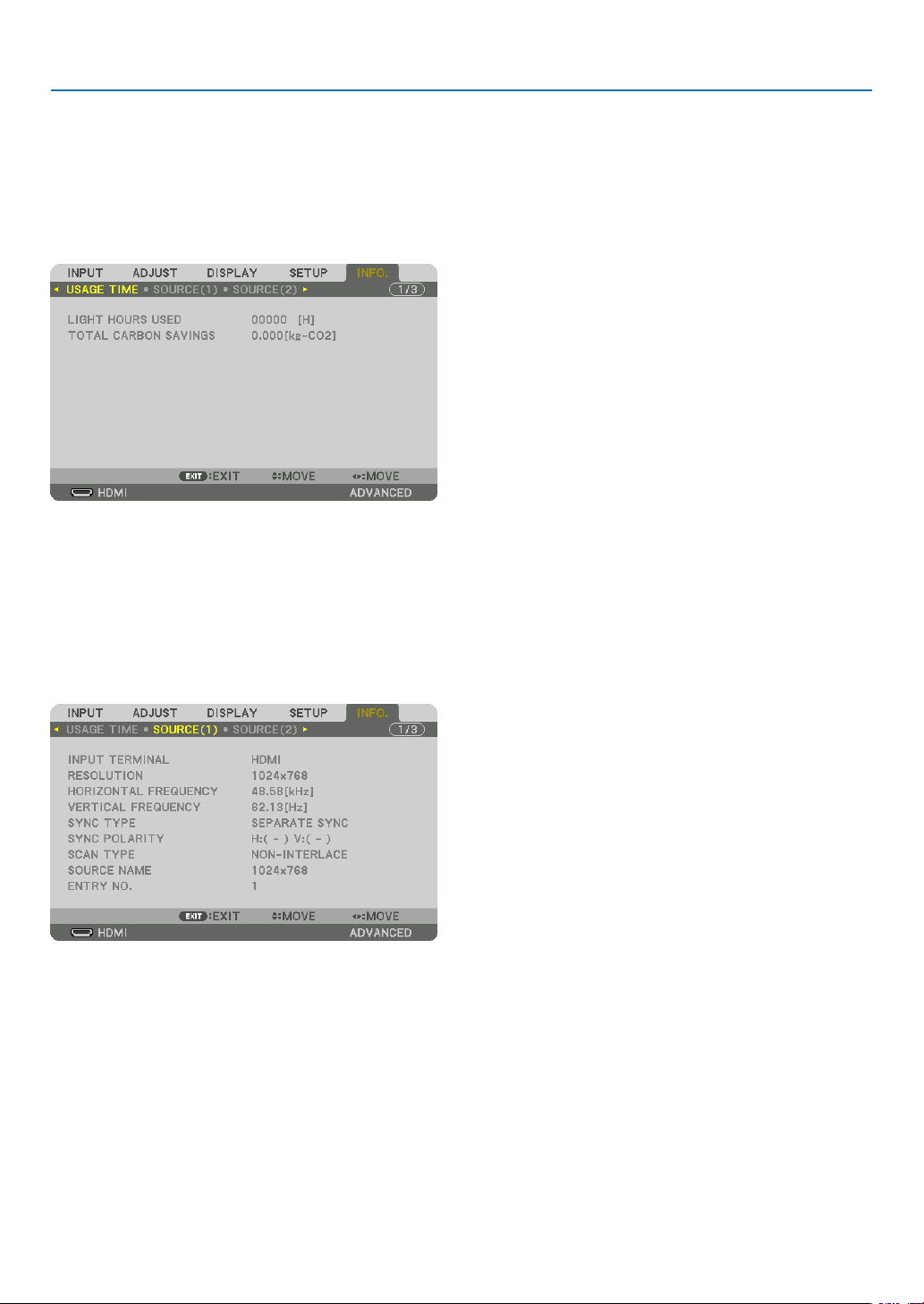
117
5. Using On-Screen Menu
❽ Menu Descriptions & Functions [INFO.]
Displaysthestatusofthecurrentsignalandlightmoduleusage.Thisitemhasninepages.Theinformationincluded
isasfollows:
TIP:PressingtheHELPbuttonontheremotecontrolwillshowthe[INFO.]menuitems.
[USAGE TIME]
[LIGHTHOURSUSED](H)
[TOTALCARBONSAVINGS](kg-CO2)
• [TOTALCARBONSAVINGS]
Thisdisplaystheestimatedcarbonsavinginformationinkg.Thecarbonfootprintfactorinthecarbonsavingcal-
culationisbasedontheOECD(2008Edition).(→page31)
[SOURCE(1)]
INPUTTERMINAL RESOLUTION
HORIZONTALFREQUENCY VERTICAL FREQUENCY
SYNCTYPE SYNC POLARITY
SCANTYPE SOURCE NAME
ENTRYNO.
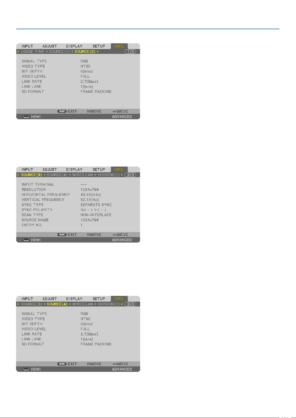
118
5. Using On-Screen Menu
[SOURCE(2)]
SIGNALTYPE VIDEOTYPE
BITDEPTH VIDEO LEVEL
LINKRATE LINKLANE
3DFORMAT
[SOURCE(3)]
INPUTTERMINAL RESOLUTION
HORIZONTALFREQUENCY VERTICAL FREQUENCY
SYNCTYPE SYNC POLARITY
SCANTYPE SOURCE NAME
ENTRYNO.
[SOURCE(4)]
SIGNALTYPE VIDEOTYPE
BITDEPTH VIDEO LEVEL
LINKRATE LINKLANE
3DFORMAT
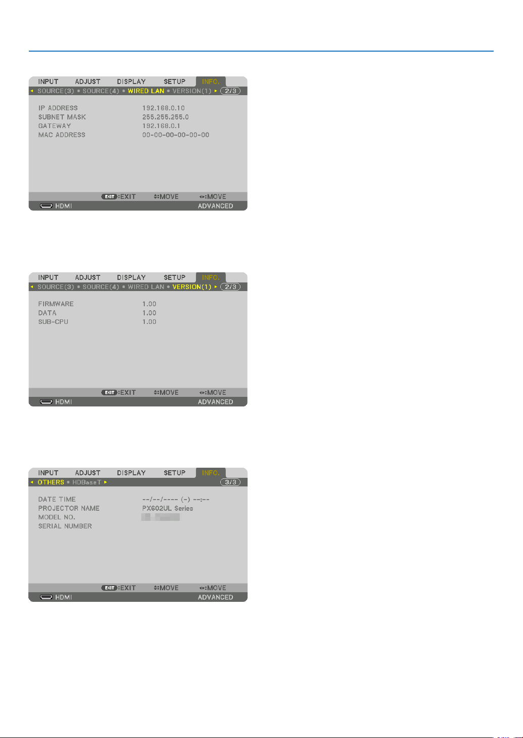
119
5. Using On-Screen Menu
[WIRED LAN]
IPADDRESS SUBNETMASK
GATEWAY MACADDRESS
[VERSION(1)]
FIRMWARE DATA
SUB-CPU
[OTHERS]
DATETIME PROJECTORNAME
MODELNO. SERIALNUMBER
CONTROLID(when[CONTROLID]isset)

120
5. Using On-Screen Menu
[HDBaseT]
SIGNALQUALITY OPERATIONMODE
LINKSTATUS HDMISTATUS
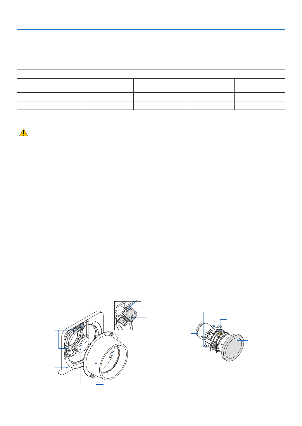
121
❶ Mounting a lens (sold separately)
Thisprojectorcanbeusedwith3kindsofoptionallenses(soldseparately).Thechartbelowshowscompatiblelenses
accordingtotheprojectormodel.ThedescriptionsherearefortheNP35ZL(standardzoom)lens.Mountotherlenses
inthesamemanner.Seepage164forlensoptions.
Lens(model)
Projector(modelname) NP34ZL
Shortfocuszoom
NP35ZL
Standardzoom
NP36ZL
Standardzoom
NP37ZL
Longfocuszoom
PX602UL-WH/PX602UL-BK Ye s Yes No Ye s
PX602WL-WH/PX602WL-BK Ye s Ye s Ye s Ye s
Yes=canbemounted,No=cannotbemounted
WARNING:
(1)Turnoffthepowerandwaitforthecoolingfantostop,(2)turnoffthemainpowerswitch,(3)disconnectthe
powercordandwaitfortheunittocoolbeforemountingorremovingthelens.Failuretodosocanresultineye
injury,electricshock,orburninjuries.
NOTE:
• Theprojectorandlensesaremadeofprecisionparts.Donotsubjectthemtoshockorexcessiveforces.
• Removetheseparatelysoldlenswhenmovingtheprojector.Ifnot,thelenscouldbesubjecttoshockwhiletheprojectorisbeing
moved, damaging the lens and the lens shift mechanism.
• Whendismountingthelensfromtheprojector,returnthelenspositiontothehomepositionbeforeturningoffthepower.Failure
to do so may prevent the lens from being mounted or dismounted because of narrow space between the projector and the lens.
• Nevertouchthelenssurfacewhiletheprojectorisoperating.
• Beverycarefulnottoletdirt,grease,etc.,onthelenssurfaceandnottoscratchthelenssurface.
• Performtheseoperationsonaatsurfaceoverapieceofcloth,etc.,topreventthelensfromgettingscratched.
• Whenleavingthelensofftheprojectorforlongperiodsoftime,mountthedustcapontheprojectortopreventdustordirtfrom
gettinginside.Ifthelensremainsdetachedfromtheprojectorforlongperiodsoftime,dustmaycollectwithintheopticalunit
and damage the lens, causing deterioration of projected image.
• Othertypesoflensescannotbemountedonthisprojector.TheNP34ZL/NP35ZL/NP36ZL/NP37ZLseriesoflensescannotbe
mounted onto other projector models.
Part Names of the Lens Mount
AttachingtheLensMount
Rotateandalignthe3angesonthelenswiththe3angecatchesonthelensmount.Thelenscanbesecuredto
themountusingalockmechanism.
“TOP”orientationindicator
Lenscap
Flange
(3places)
Lockingscrew
Hook(3places)
Lenshood
Lockreleasebutton
Lenscap
Catch
(3places)
Frontpanel
Protectivecap
Mountlock
Lens
6. Connecting to Other Equipment
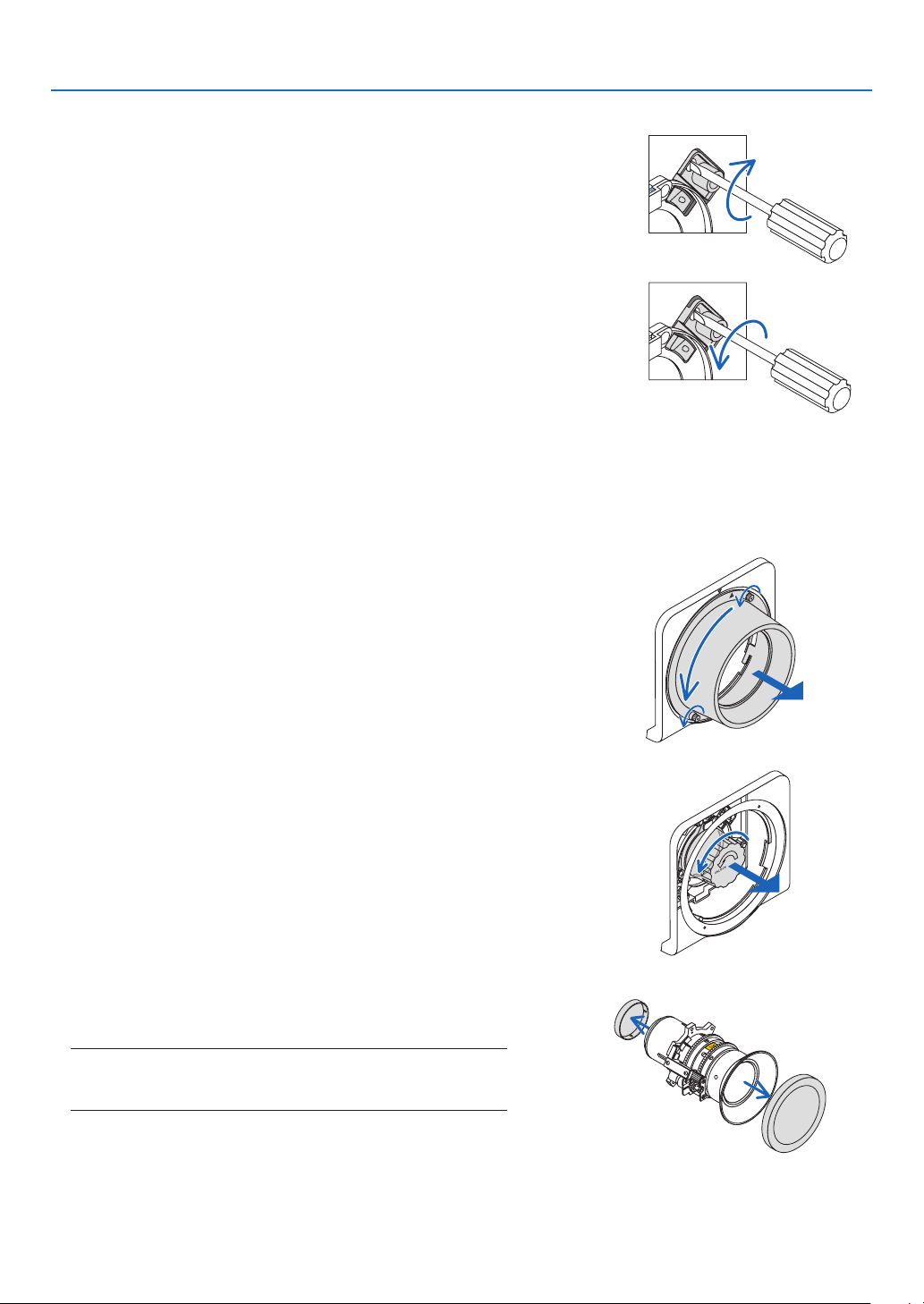
122
6. Installation and Connections
Usingthelockmechanism
Release:Lockingscrewistightened
Thelenscanbeattachedordetached(factorydefaultsetting).
Lock:Lockingscrewisuntightened
Thelenscannotbeattachedordetached.Pressingthelockreleasebut-
tonallthewayindisablesthelockmechanismandallowsthelenstobe
attachedordetached.
Mounting the lens
Preparation:
Prepareaatheadscrewdriver.
* Theillustrationomitstheprojectorcabinet.
1. Remove the lens hood.
(1)Loosenthe2 screwspinching and turningthem counter-
clockwisebyyourngers.
• Thescrewswillremaintostaynotberemoved.
(2)Removethelenshoodbyturningitcounterclockwise.The
hooksonthelenshoodwilldisengagefromthefrontpanel.
2. Remove the protective cap.
• Theunitisshippedfromthefactorywiththeprotectivecap
installed.
Turntheprotectivecapcounterclockwisetoreleaseitfromthe
catch.Removethecap.
• Pleasestoretheprotectivecapinasafeplace.
3. Removethelenscapsoneithersideofthelens.
• TheNP35ZLlensunitisusedasanexample.
• Pleasestorethelenscapinasafeplace.
NOTE:
• Besuretoremovethelenscap.Ifthelightsourceisturnedonwhen
the lens cap remains on the lens, it may be cause of malfunction.
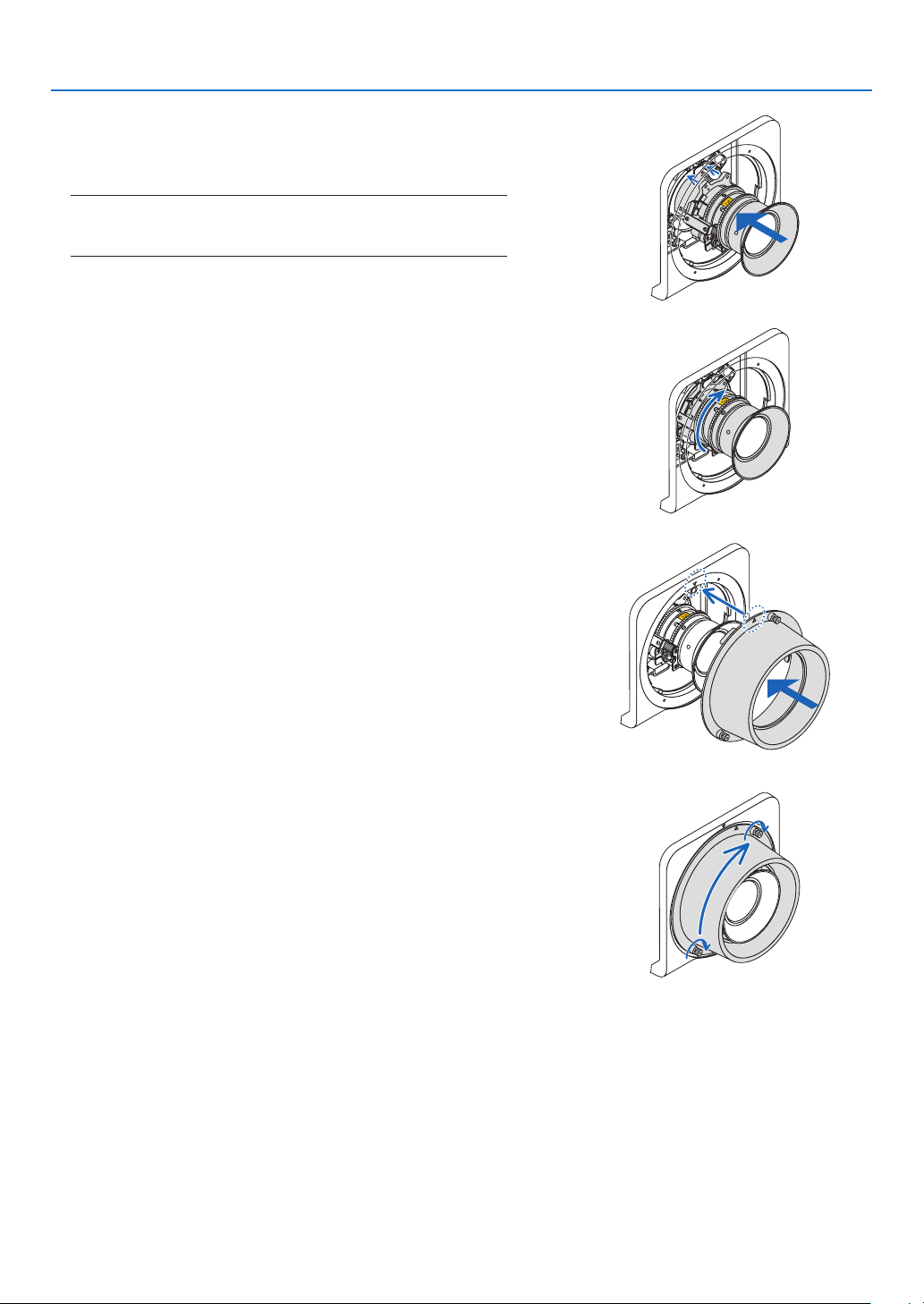
123
6. Installation and Connections
4. Withthe“TOP”orientationindicatorfacingupwards,insert
the lens into the lens mount.
Aligntheangeontheupperportionofthelenswiththecatch
ontheleftsideofthelensmount.
NOTE:
• Insertthelenscarefullytoavoiditfromdamagebyknockingagainst
the lens mount.
5. Turn the lens clockwise until it clicks into place.
The3angeshavenowengagedwiththe3catchesandthe
lensunithasbeenmounted.
• Tolockthelensunitsee“Usingthelockmechanism”onthe
previouspage.
6. Mountthelenshoodtothefrontpanel.
(1)Align▲markedonthelenshoodandthefrontpaneltop.
(2)Turnthelenshoodclockwise.
Thehooksintherearwillengagewiththefrontpanelange.
(3)Tightenthe2screwsbyyourngers.
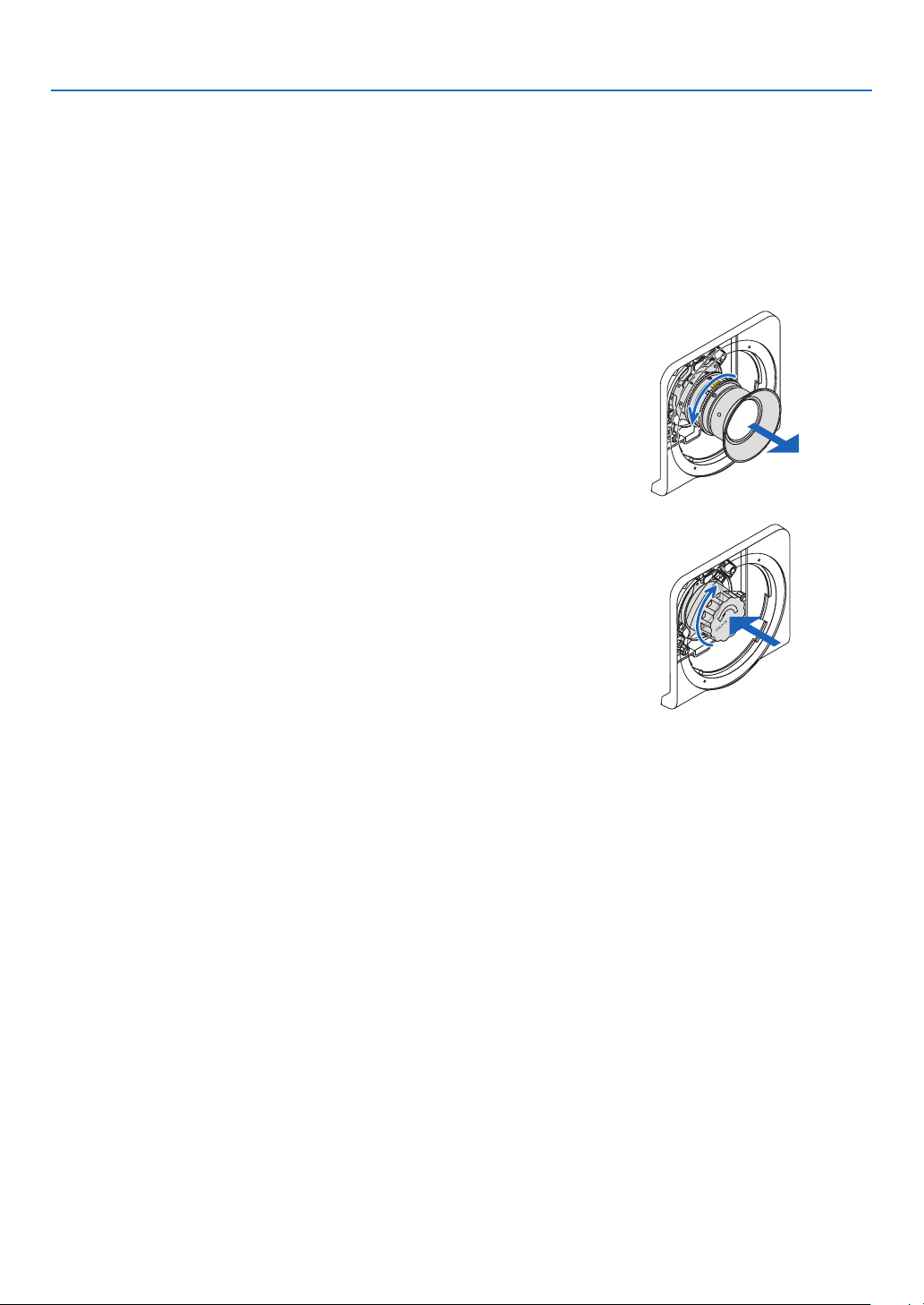
124
6. Installation and Connections
Removing the lens
Preparation:
Returnthelenspositiontothehomeposition.(→page19)
Afterthelensshifthasmoved,refertothewarningonpage19andturnoffthepower.
1. Remove the lens hood.
RefertoStep1under“Mountingthelens”.
• Ifthelensunitislockedpleaseseepage122andfollowthe
instructionsunderUsingtheLockFunctiontounlockit.
2. Turnthelenscounterclockwisetoremoveitfromthecatch,
andslowlypullforwardtoremove.
• Afterremovingthelens,mountthelenscaps(frontandback)
includedwiththelensbeforestoringthelens.
• Toreplacethelens,seeStep3of“Mountingthelens”.
3. Mount the protective cap.
Aligntheangeontheprotectivecaptotheleftsideofthecatch
andturnclockwiseuntilitclicksintoplace.
4. Mount the lens hood to the panel.
RefertoStep7under“Mountingthelens”.
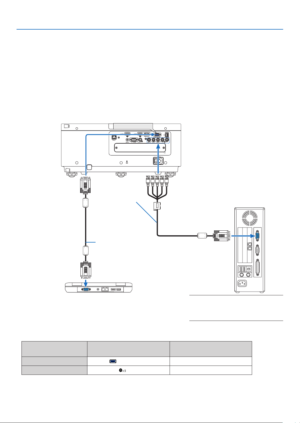
125
6. Installation and Connections
❷ Making Connections
Acomputercable,BNCcable(5-coretype),HDMIcable,oraDisplayPortcablecanbeusedtoconnecttoacomputer.
Theconnectioncableisnotenclosedwiththeprojector.Pleasegetreadyasuitablecablefortheconnection.
Analog RGB signal connection
• Connectthecomputercabletothedisplayoutputterminal(miniD-sub15pin)onthecomputerandtheCOMPUTER
1INterminalontheprojector.Pleaseuseacomputercableattachedwithaferritecore.
• Whenconnectingthedisplayoutputterminal(miniD-sub15pin)onthecomputertotheBNCinputterminal,use
aconversioncabletoconverttheBNCcable(5core)toaminiD-sub15pincable.
• Selectthesourcenameforitsappropriateinputterminalafterturningontheprojector.
Inputterminal
SOURCEbuttonontheprojector
cabinet
Buttonontheremotecontrol
COMPUTER1IN COMPUTER COMPUTER1
BNC BNC COMPUTER2
COMPUTER 1 IN
Computercable(soldcommercially)
RGB-to-BNCcable
(notsupplied)
NOTE:Pleasechecktheoperatingmanualof
the computer as the name, position and direc-
tion of the terminal may differ depending on
the computer.
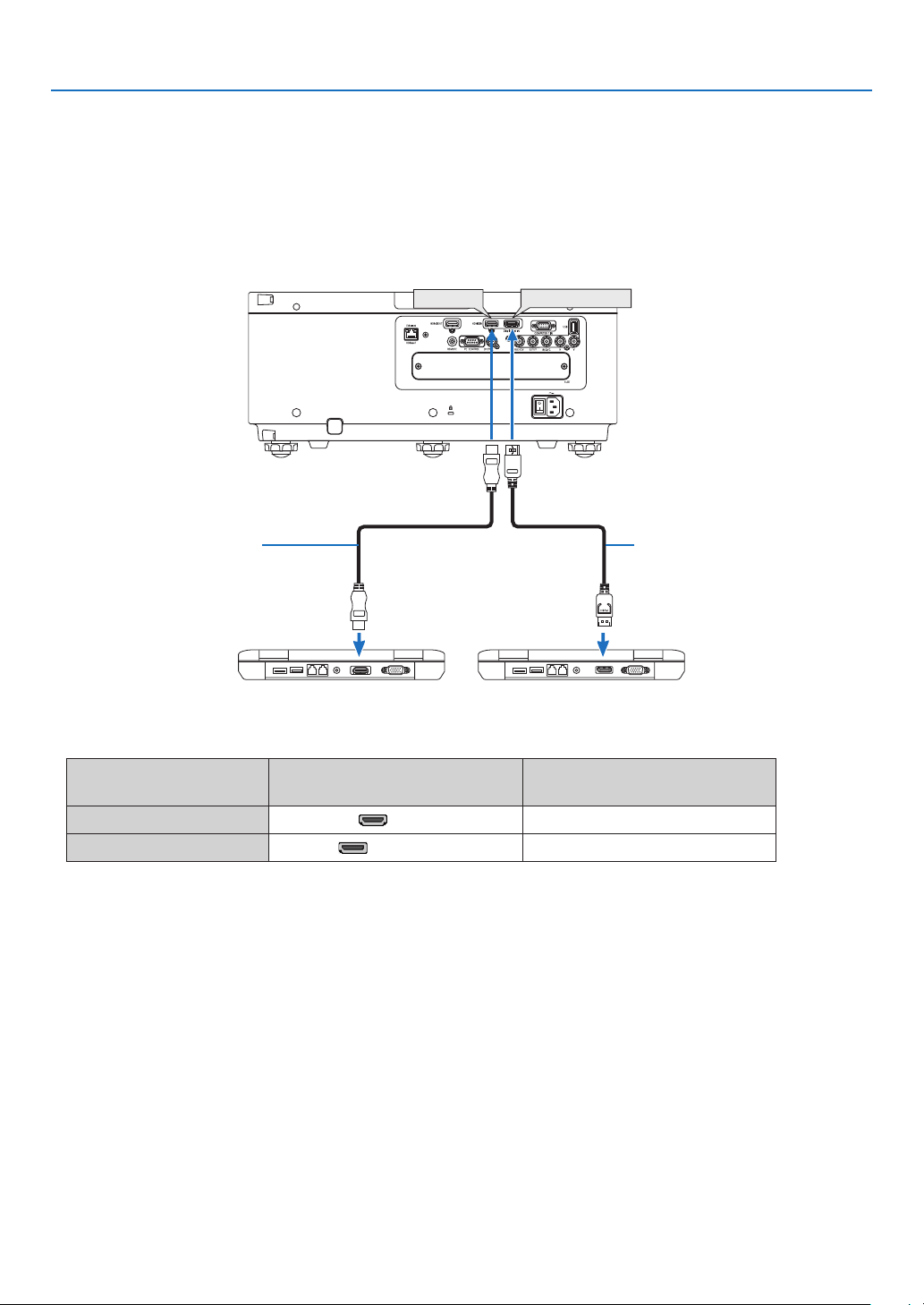
126
6. Installation and Connections
Digital RGB signal connection
• ConnectacommerciallyavailableHDMIcablebetweenthecomputer’sHDMIoutputterminalandtheprojector’s
HDMIINterminal.
• ConnectacommerciallyavailableDisplayPortcablebetweenthecomputer’sDisplayPortoutputterminalandthe
projector’sDisplayPortINterminal.
• Selectthesourcenameforitsappropriateinputterminalafterturningontheprojector.
Inputterminal
SOURCEbuttonontheprojector
cabinet
Buttonontheremotecontrol
HDMIIN HDMI HDMI
DisplayPortIN DisplayPort DisplayPort
DisplayPort IN
HDMI IN
HDMIcable(notsupplied) DisplayPortcable(notsupplied)

127
6. Installation and Connections
CautionswhenconnectinganHDMIcable
• UseacertiedHighSpeedHDMI
®
CableorHighSpeedHDMI
®
CablewithEthernet.
CautionswhenconnectingaDisplayPortcable
• UseacertiedDisplayPortcable.
• Dependingonthecomputer,sometimemayberequireduntiltheimageisdisplayed.
• SomeDisplayPortcables(commerciallyavailable)havelocks.
• Todisconnectthecable,pressthebuttononthetopofthecable’sterminal,thenpullthecableout.
• PowercanbesuppliedtotheconnectingdevicefromtheDisplayPortINterminal(maximumof1.65W).However,
powerwillnotbesuppliedtothecomputer.
• WhensignalsfromadevicethatusesasignalconverteradapterareconnectedtotheDisplayPortINterminal,in
somecasestheimagemaynotbedisplayed.
• WhentheHDMIoutputofacomputerisconnectedtotheDisplayPortINterminal,useaconverter(commercially
available).
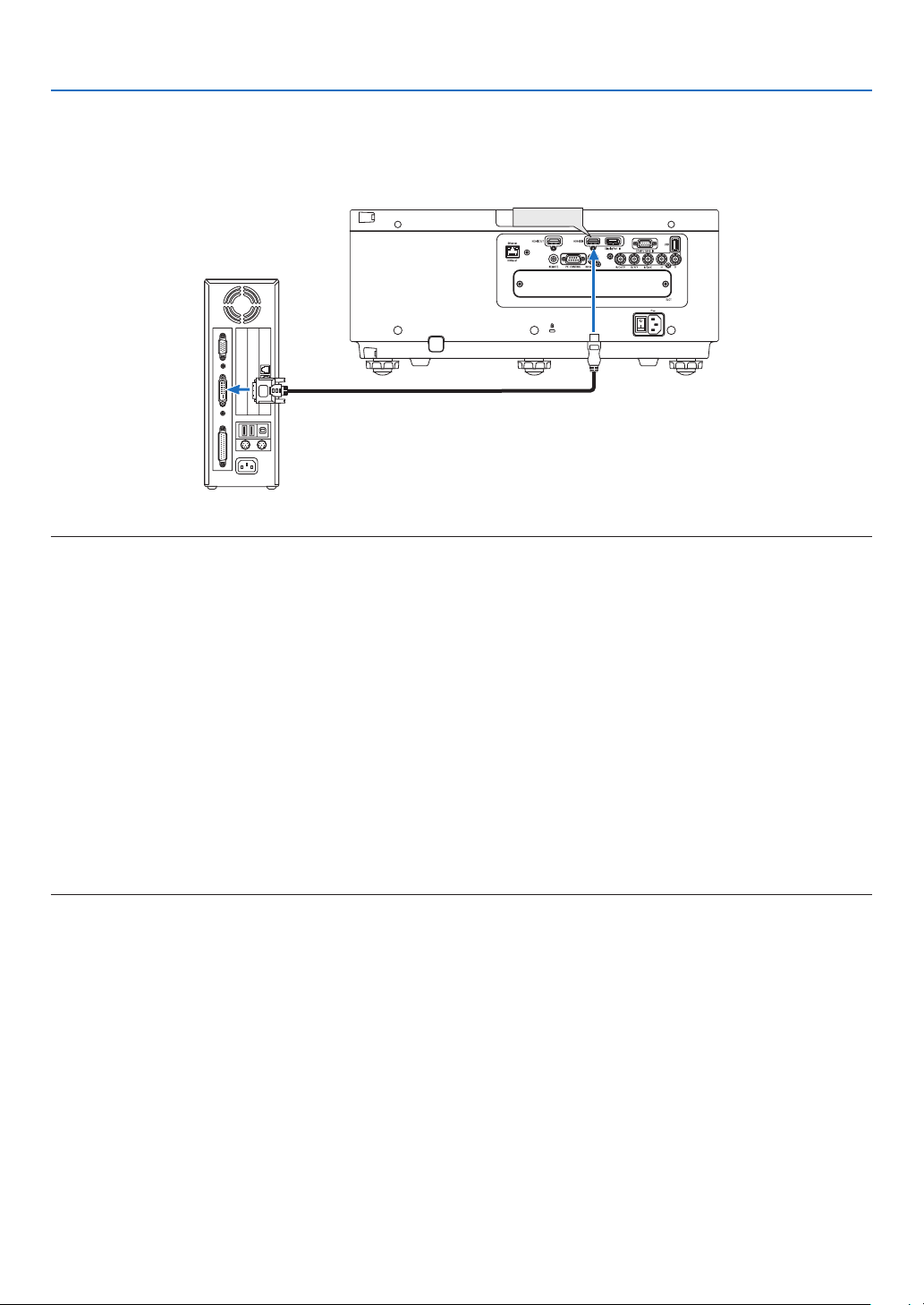
128
6. Installation and Connections
CautionswhenusingaDVIsignal
• WhenthecomputerhasaDVIoutputterminal,useacommerciallyavailableconvertercabletoconnectthecom-
putertotheprojector’sHDMIINterminal(onlydigitalvideosignalscanbeinput).
HDMI IN
NOTE:WhenViewingaDVIDigitalSignal
• Turnoffthepowerofthecomputerandprojectorbeforeconnectingdevices.
• Whenavideodeckisconnectedviaascanconverter,etc.,thedisplaymaynotbecorrectduringfast-forwardingandrewinding.
• UseaDVI-to-HDMIcablecompliantwithDDWG(DigitalDisplayWorkingGroup)DVI(DigitalVisualInterface)revision1.0stan-
dard.Thecableshouldbewithin197"/5mlong.
• TurnofftheprojectorandthePCbeforeconnectingtheDVI-to-HDMIcable.
• ToprojectaDVIdigitalsignal:Connectthecables,turntheprojectoron,thenselecttheHDMI.Finally,turnonyourPC.
Failuretodosomaynotactivatethedigitaloutputofthegraphicscardresultinginnopicturebeingdisplayed.Shouldthishappen,
restartyourPC.
• SomegraphicscardshavebothanalogRGB(15-pinD-Sub)andDVI(orDFP)outputs.Useofthe15-pinD-Subterminalmay
result in no picture being displayed from the digital output of the graphics card.
• DonotdisconnecttheDVI-to-HDMIcablewhiletheprojectorisrunning.Ifthesignalcablehasbeendisconnectedandthen
reconnected,animagemaynotbecorrectlydisplayed.Shouldthishappen,restartyourPC.
• TheCOMPUTER1INterminalssupportWindowsPlugandPlay.TheBNCinputterminaldoesnotsupportWindowsPlugand
Play.
• AMacsignaladapter(commerciallyavailable)mayberequiredtoconnectaMaccomputer.
ToconnectaMaccomputerequippedwithaMiniDisplayPorttotheprojector,useacommerciallyavailableMiniDisplayPort→
DisplayPortconvertercable.
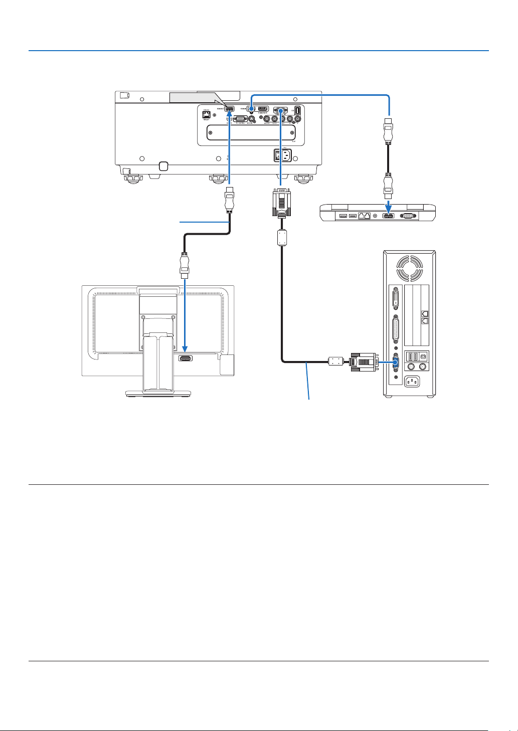
129
6. Installation and Connections
HDMI IN
HDMI OUT
Connecting an External Monitor
Youcanconnectaseparate,externalmonitortoyourprojectortosimultaneouslyviewonamonitorthecomputer
analogimageyou’reprojecting.
• BNC(CV)componentvideosignalsandBNC(Y/C)S-videosignalswillnotbeoutput.
• PleaserefertoPage52whendisplayingthePIP/PBPscreen.
NOTE:
• WhenoutputtingHDMIsignals,turnonthepowerofthevideodeviceontheoutputsideandkeepitconnectedbeforeinputting
videosignalsintothisdevice.TheHDMIOUTterminalsoftheprojectorareequippedwithrepeaterfunctions.Whenadeviceis
connectedtotheHDMIOUTterminal,theresolutionoftheoutputsignalislimitedbytheresolutionsupportedbytheconnected
device.
• InthecaseoftheHDMIOUTterminaloftheprojector,thetheoreticalnumberofunitsthatcanbeconnectedinaseriesisseven.
The maximum number of units that can be connected may be reduced by the external environment and quality of the signal and
cable,etc.ThenumberofunitsthatcanbeconnectedmaydifferdependingontheHDCPversion,restrictiononthenumberof
HDCPrepeatersinthesourcedeviceandthequalityofthecable.Theoverallsystemneedstobecheckedinadvancewhenbuild-
ing a system.
• Whenthe[STANDBYMODE]issetto[NORMAL],videowillnotbeoutputiftheprojectorgoesintothestandbymode.Setthe
modeto[NETWORKSTANDBY],turnonthepowerofthetransmissiondeviceandkeepitinaconnectedstate.
• Whenthe[STANDBYMODE]ofthisdeviceissetto[NORMAL],HDMIsignalswillnotbeoutput.TooutputHDMIsignals,setthe
[STANDBYMODE]to[NETWORKSTANDBY],turnonthepowersupplyofthetransmissiondeviceandkeepitconnected.
• HDMIrepeaterfunctionwillnotbefunctionedifswitchingterminalsandputtingin/pullingouttheHDMIcableisperformedon
the 2nd projector and after.
Computercable(VGA)(notsupplied)
HDMIcable(notsupplied)
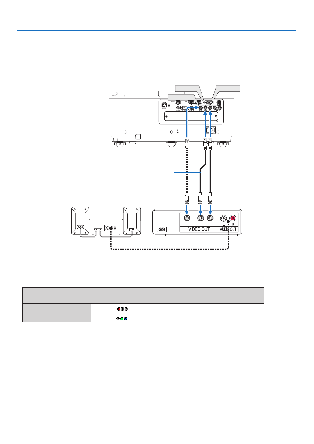
130
6. Installation and Connections
Connecting Your Blu-ray Player or Other AV Equipment
Componentvideosignal/S-videosignalconnection
• Selectthesourcenameforitsappropriateinputterminalafterturningontheprojector.
Inputterminal
SOURCEbuttonontheprojector
cabinet
Buttonontheremotecontrol
BNC(CV) BNC(CV) VIDEO
BNC(Y/C)
BNC(Y/C) S-VIDEO
CV YC
BNC(CV)
BNC(Y)
BNC(C)
BNCcable(notsupplied)
Audioequipment
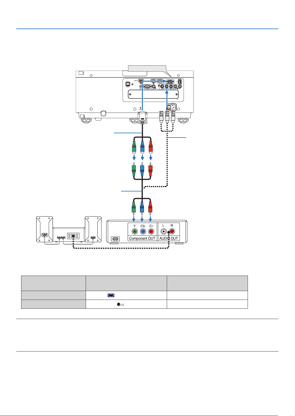
131
6. Installation and Connections
Connecting Component Input
• Selectthesourcenameforitsappropriateinputterminalafterturningontheprojector.
Inputterminal
SOURCEbuttonontheprojector
cabinet
Buttonontheremotecontrol
COMPUTER1IN COMPUTER COMPUTER1
BNC BNC COMPUTER2
NOTE:
• Whenthesignalformatissetto[AUTO](defaultfactorysettingwhenshipped),thecomputersignalandcomponentsignalare
automaticallydistinguished and switched. If the signals cannot be distinguished, select [COMPONENT] under [ADJUST] →
[VIDEO]→[SIGNALTYPE]intheon-screenmenuoftheprojector.
• ToconnecttoavideodevicewithaDterminal,usethesoldseparatelyDterminalconverteradapter(modelADP-DT1E).
COMPUTER 1 IN
15-pin-to-RCA(female)×3cableadapter
(ADP-CV1E)
BNC(male)-to-RCA(male)conversion
cable×3(soldcommercially)
ComponentvideoRCA×3cable(notsup-
plied)
Blu-rayplayer
AudioEquipment
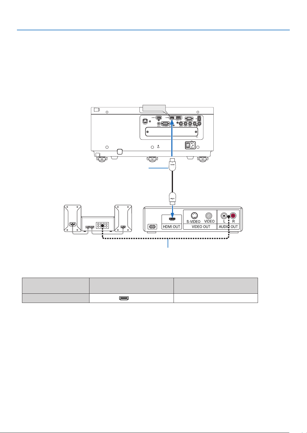
132
6. Installation and Connections
Connecting HDMI Input
YoucanconnecttheHDMIoutputofyourBlu-rayplayer,harddiskplayer,ornotebooktypePCtotheHDMIINterminal
ofyourprojector.
Inputterminal
SOURCEbuttonontheprojector
cabinet
Buttonontheremotecontrol
HDMIIN HDMI HDMI
TIP:ForusersofaudiovideoequipmentwithanHDMIterminal:
Select“Enhanced”ratherthan“Normal”ifHDMIoutputisswitchablebetween“Enhanced”and“Normal”.
This will provide improved image contrast and more detailed dark areas.
Formoreinformationonsettings,refertotheinstructionmanualoftheaudiovideoequipmenttobeconnected.
• WhenconnectingtheHDMIINterminaloftheprojectortotheBlu-rayplayer,theprojector’svideolevelcanbe
madesettingsinaccordancewiththeBlu-rayplayer’svideolevel.Inthemenuselect[ADJUST]→[VIDEO]→
[VIDEOLEVEL]andmakenecessarysettings.
HDMI IN
Audiocable(notsupplied)
HDMIcable(notsupplied)
UseHighSpeedHDMI
®
Cable.
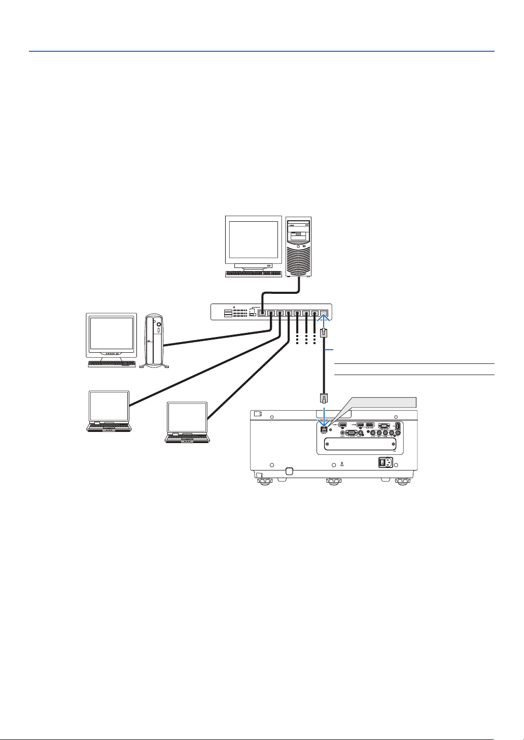
133
6. Installation and Connections
Connecting to a Wired LAN
TheprojectorcomesstandardwithaEthernet/HDBaseTport(RJ-45)whichprovidesaLANconnectionusingaLAN
cable.
TouseaLANconnection,youarerequiredtosettheLANontheprojectormenu.Select[SETUP]→[NETWORK
SETTINGS]→[WIREDLAN].(→page107).
Example of LAN connection
ExampleofwiredLANconnection
Ethernet/HDBaseT
Server
Hub
LANcable(notsupplied)
NOTE:UseaCategory5orhigherLANcable.
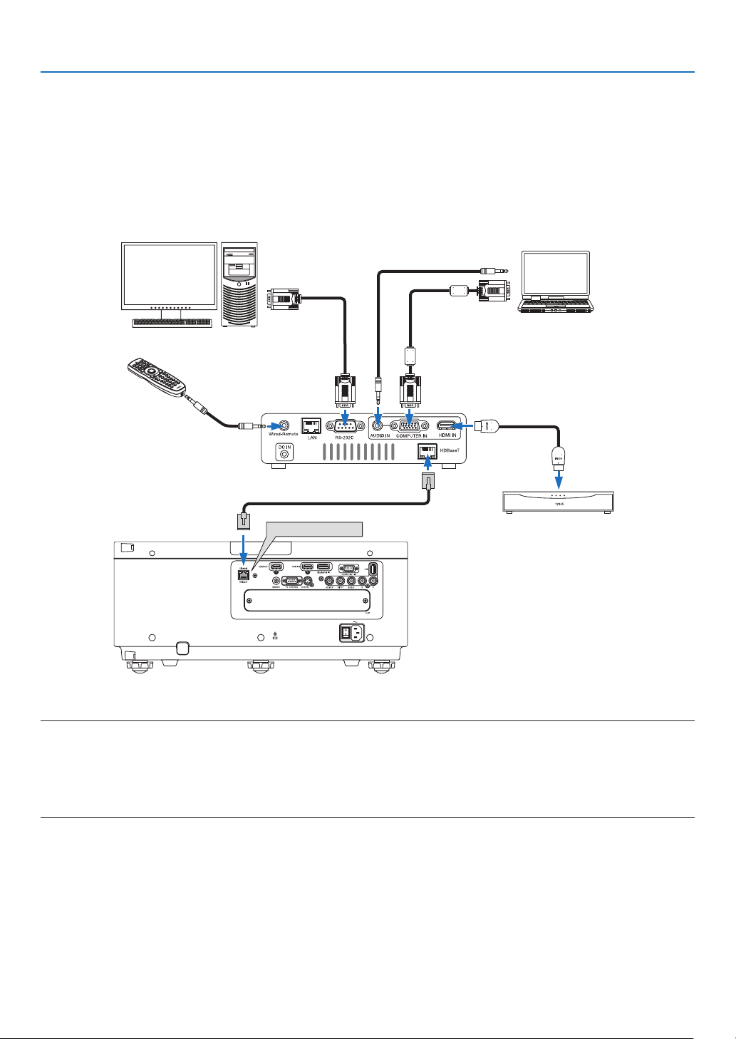
134
6. Installation and Connections
Connecting to a HDBaseT transmission device (sold commercially)
HDBaseTisaconnectionstandardforhomeappliancesthatisestablishedbytheHDBaseTAlliance.
UseaLANcablesoldcommerciallytoconnecttheEthernet/HDBaseTportoftheprojector(RJ-45)toaHDBaseT
transmissiondevicesoldcommercially.
TheEthernet/HDBaseTportoftheprojectorsupportsHDMIsignals(HDCP)fromtransmissiondevices,controlsignals
fromexternaldevices(serial,LAN)andremotecontrolsignals(IRcommands).
Connection example
Ethernet/HDBaseT
Computer(forcontroluse)
Computer(foroutputuse)
Exampleofatransmissiondevice
Remotecontrol
HDMIoutputvideodevice
NOTE:
• Pleaseuseashieldedtwistedpair(STP)cableofCategory5eorhigherfortheLANcable(soldcommercially).
• ThemaximumtransmissiondistanceovertheLANcableis100m.(themaximumdistanceis70mfora4Ksignal)
• Pleasedonotuseothertransmissionequipmentbetweentheprojectorandtransmissionequipment.Thepicturequalitymaybe
deteriorated as a result.
• ThisprojectorisnotguaranteedtoworkwithallHDBaseTtransmissiondevicessoldcommercially.
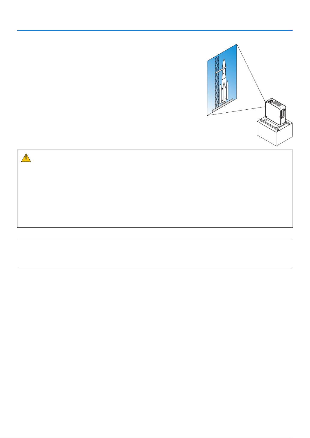
135
6. Installation and Connections
Portrait projection (vertical orientation)
Byusingasafetycover(soldseparately),theprojectorcanbemounted
verticallytodisplaycomputerimagesinportraitorientation.
Ifthesafetycoverismissing,thepowerwillnotturnon.
Allscreens,suchastheon-screenmenus,willberotatedinthecounter-
clockwisedirection.
Theprojectorisequippedwithasensortoautomaticallydetecttheinstal-
lationstate.
Precautionsduringinstallation
• Pleasedonotinstalltheprojectorinaverticalorientationontopoftheoorortableonitsown.Ifnot,thepro-
jectormayfallover,resultingininjury,damageormalfunction.
• Forverticalinstallation,installtheprojectorwiththeintakevent(safetycover)facingdownwards.Astandfor
supportingtheprojectorneedstobemadeforthispurpose.Inthiscase,thestandmustbedesignedsuchthat
thecenterofgravityoftheprojectorislocatedwellwithinthelegsofthestand.Ifnot,theprojectormayfallover
andresultininjury,damageandmalfunction.
• Donotobstructtheintakeventonthesafetycover.Theprojectormayotherwiseoverheat,causingreand
malfunction.
NOTE:
• Whenusingasafetycover,thepowerturnsononlywhentheprojectorventilationintakeisfacingdown.Iftheintakeventfaces
any other direction, the power will not turn on.
• Iftheprojectorismountedverticallywithoutasafetycover,thepowerwillnotturnon.
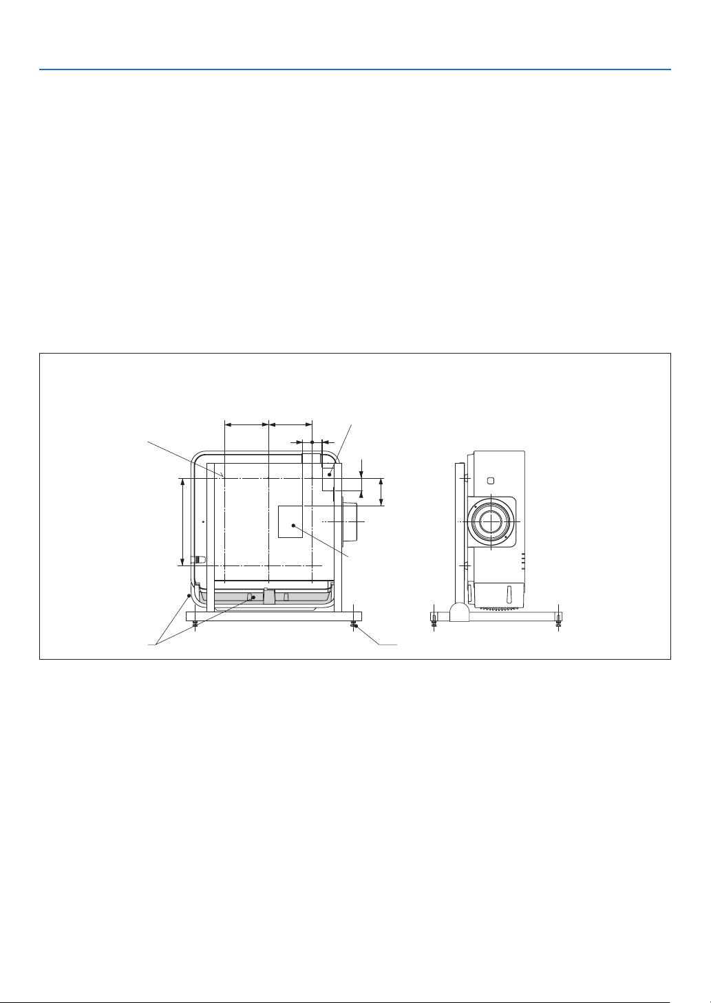
136
6. Installation and Connections
Design and manufacturing conditions for the stand
1. Todisplayimagesinportraitorientation,useasafetycover(soldseparately).(→page137)
2. Pleasehireaninstallationserviceprovider(forafee)forthedesignandmanufactureofacustomizedstandtobe
usedforportraitprojection.Pleaseensurethatthedesigncomplieswiththefollowingconditions:
• Thereisanintakeventopeningonthesafetycover.Donotobstructthisopening.
• Thereare2ventilationholesatthebottomoftheprojector.Theseholesshouldremainunobstructed.
• Usethe6screwholesatthebackoftheprojectortosecureittothestand.
Screwholecenterdimension:300×300(pitch=150)mm
Screwholedimensionontheprojector:M4withamaximumdepthof8mm
3ofthelegscanbeunscrewedforremoval.
• Horizontaladjustmentmechanism(forexample,boltsandnutsin4places)
• Pleasedesignthestandsothatitdoesnoteasilytoppleover.
* Werecommendcombiningceilingmounts(modelNP15CM,soldseparately)withanangleadjustmentmechanism.
Reference drawings
* Thedrawingshowingthedimensionalrequirementsisnotanactualstanddesigndrawing.
32
34
150
150
34
85
300
[Side View] [Front View]
Screw holes for 6 -
M4 use
□ 84 × 108 holes
(Intake vent)
□ 40 × 78 holes
(Exhaust vent)
(Unit: mm)
Horizontal adjusterIntake vent
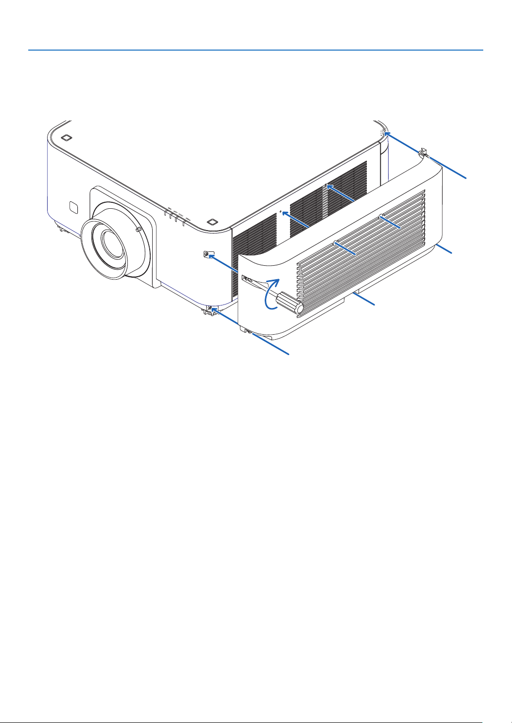
137
6. Installation and Connections
Mountingthesafetycover(soldseparately)
Theprojectorisequippedaswitchforchangingtoverticalmountportraitprojection.Mountthesafetycoverandplace
verticallytochangetoverticalorientationmode.
1. Insert and tighten the 7 screws (turning clockwise) to mount to the projector.
* Ifusinginnormalhorizontalorientation,makesuretoremovethesafetycover.
Toremove,unscrewthe7screws(turningcounter-clockwise).
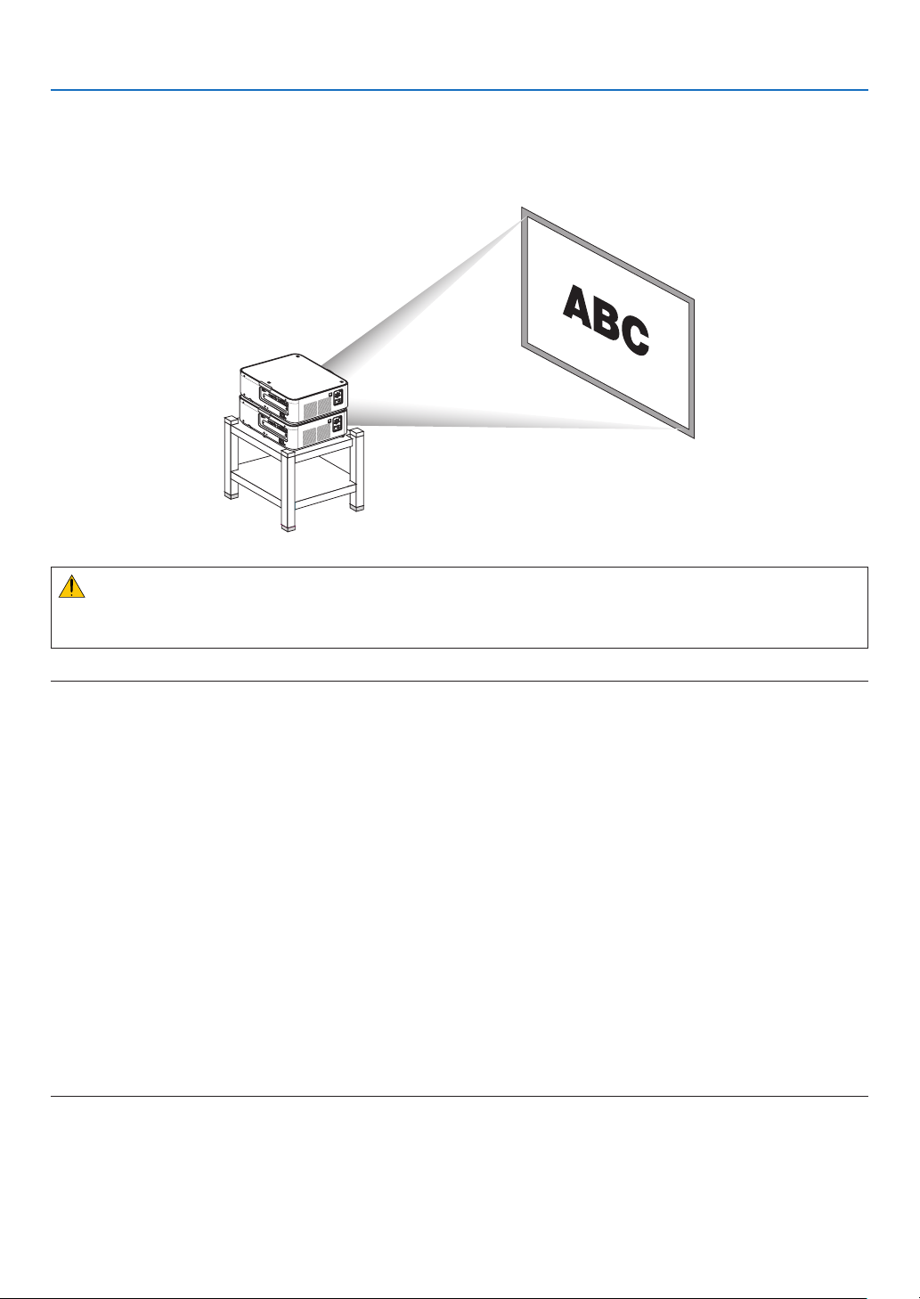
138
6. Installation and Connections
Stacking projectors
Theprojectedimagebrightnesscanbedoubledbygravitystackinguptotwoprojectorswithoutexternalsupport.This
iscalled“StackingProjection”.
2projectorscanbestackedontopofeachotherfor“Stacking”setup.
CAUTION:
Aminimumoftwopersonsarerequiredtocarrytheprojector.Otherwisetheprojectormaytumbleordrop,causing
personalinjury.
NOTE:
• Projectorswithdifferentmodelnumberscannotbegravitystacked.
Optional lenses with the same model numbers must be used for stacking projection.
• Forstackingprojectors,attachthesuppliedthreestackingholderstothetopofthelowerprojector.(→ next page)
• Itdoesnotsupportoverlayaccuracybystackedprojectors.Preciseimagesassmalltextsanddetailedgraphicscannotbeclearly
read or seen.
• Useacommerciallyavailabledistributionampliertoboththeprimary(upper)andthesecondary(lower)projectorstodistribute
signal to two outputs of the two projectors.
• Notesforstacking
- Askyourservicepersonforsettingupandadjustingprojectors.
- Setuptheprojectorsinaplaceorstructureinawaywithsufcientstrengthtosupportthecombinedweightofthetwoprojec-
tors.Thesingleprojectorwithalensweighsuptoapproximately20kg/44lbs.
- To prevent the projectors from falling, fasten them in a way to withstand earthquakes.
- Doublestackingwillcauseroomtemperaturetoincrease.Ventilatetheroomwell.
- Donotattempttostackprojectorsontheceiling.Gravitystackingcannotbedoneontheceiling.
- Warmuptheprojectorsforonehourbeforethedesiredprojectionisobtained.
- Makesurethatthepositionoftheupperprojectordoesnotexceeditsspecications.Whensettingupthetwoprojectors,
adjustable height range for the tilt feet on the upper projector is added to the total adjustable range.
- Setuptheprojectorssothattheprojectedimageshowsaslittlegeometricdistortionsaspossible.Thelensisdifferentin
geometricdistortionbetweenwide(+)andtele(−)forzoom.
- Adjustthehorizontallensshifttothelenscenter.
s
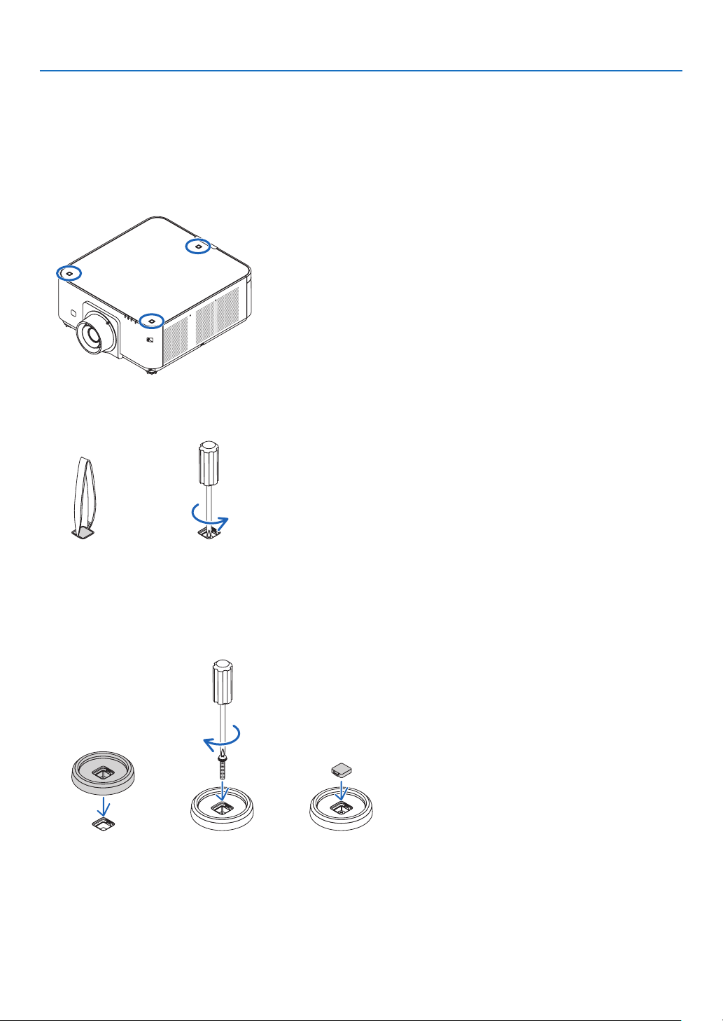
139
6. Installation and Connections
AttachingStackingHolders
Attachthreestackingholderstothreelocationsonthetopofthelowerprojector.
Preparation:
ToolsrequiredarePhillipsscrewdriver(plus-head)andthreestackingholderspackagedwiththeprojector.
Loosenthetiltfeet(threelocations)oftheprojector.
1. Remove rubber caps and screws at three locations.
(1)Useyourtweezersornailtopinchandpulluptherubbercap.
(2)Removethescrewfromasquarehole.
(1) (2)
2. Attach the three stacking holders at three locations.
(1)Placeastackingholderinasquarehole.
(2)UsethescrewremovedatStep1toxthestackingholderinthesquarehole.
(3)PuttherubbercapremovedatStep1backintothesquarehole.
• Snapthetabsonbothoftherubbercapintotheslitsonbothsidesinthesquarehole.
(1) (2) (3)
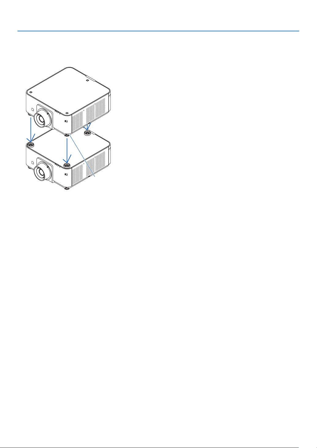
140
6. Installation and Connections
3. Putanotherprojectorontherstprojector.
Puteachtiltfootoftheupperprojectoronthestackingholders(threelocations).
• Eachtiltfoothasarubber.Placeeachtiltfootrubberonstackingholders(threelocations).
Footrubber
TIP:
• Toremovethestackingholders,performtheabovestepsinreverseorder.
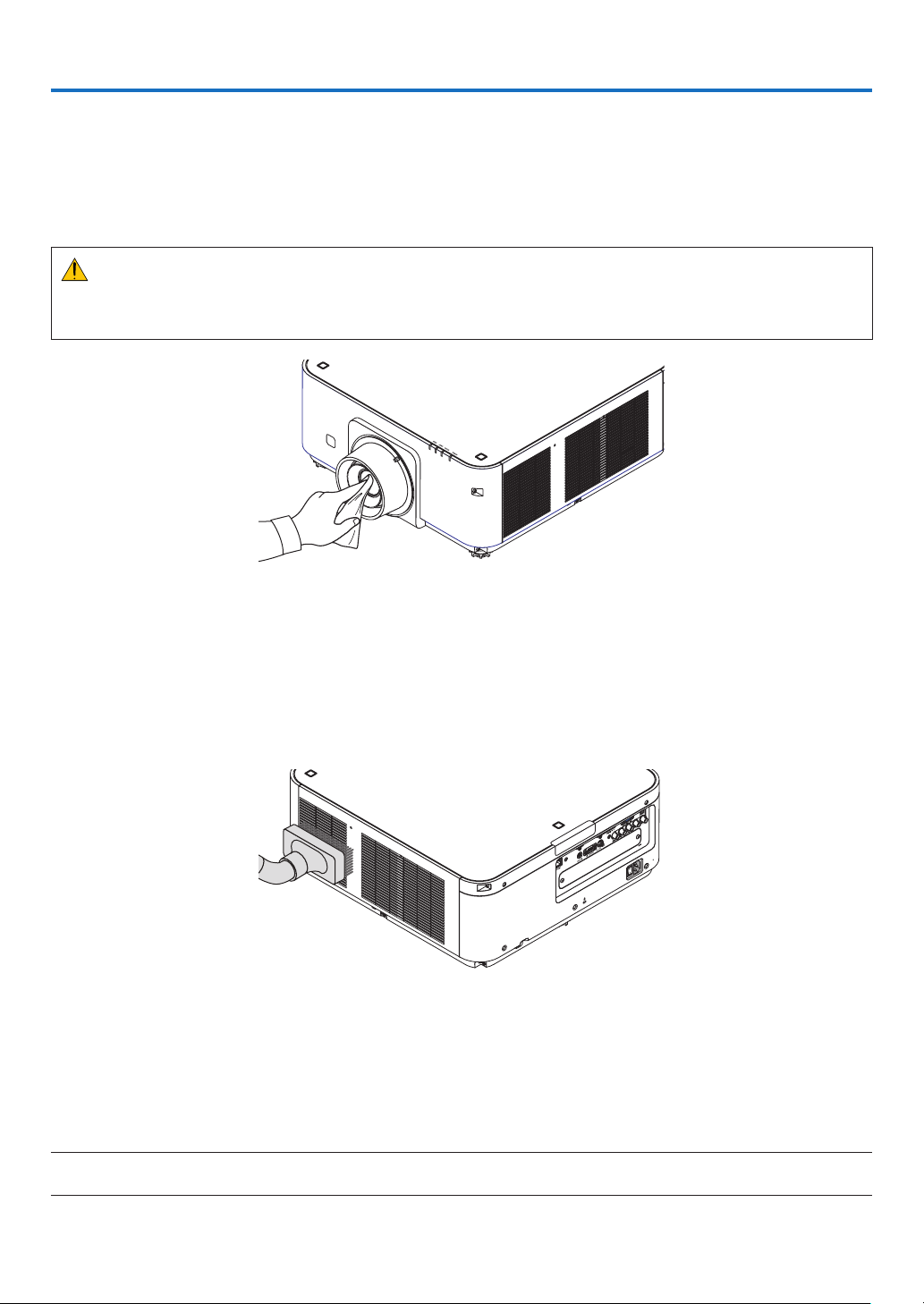
141
7. Maintenance
❶ Cleaning the Lens
• Turnofftheprojectorbeforecleaning.
• Theprojectorhasaplasticlens.Useacommerciallyavailableplasticlenscleaner.
• Donotscratchormarthelenssurfaceasaplasticlensiseasilyscratched.
• Neverusealcoholorglasslenscleanerasdoingsowillcausedamagetotheplasticlenssurface.
WARNING
• Pleasedonotuseaspraycontainingammablegastoremovedustattachedtothelens,etc.Doingsomay
resultinres.
❷ Cleaning the Cabinet
Turnofftheprojector,andunplugtheprojectorbeforecleaning.
• Useadrysoftclothtowipedustoffthecabinet.
Ifheavilysoiled,useamilddetergent.
• Neverusestrongdetergentsorsolventssuchasalcoholorthinner.
• Whencleaningtheventilationslitsorthespeakerusingavacuumcleaner,donotforcethebrushofthevacuum
cleanerintotheslitsofthecabinet.
Vacuumthedustofftheventilationslits.
• Poorventilationcausedbydustaccumulationinventilationopenings(intake,exhaust,alsoatthebottomofthe
projector)canresultinoverheatingandmalfunction.Theseareasshouldbecleanedregularly.
• Donotscratchorhitthecabinetwithyourngersoranyhardobjects
• Contactyourdealerforcleaningtheinsideoftheprojector.
NOTE:Donotapplyvolatileagentsuchasinsecticideonthecabinet,thelens,orthescreen.Donotleavearubberorvinylproduct
inprolongedcontactwithit.Otherwisethesurfacenishwillbedeterioratedorthecoatingmaybestrippedoff.

142
8. User Supportware
❶ Operating Environment for Software Included on CD-ROM
Names and Features of Bundled Software Programs
Nameofsoftwareprogram Features
VirtualRemoteTool
(Windowsonly)
Whenthecomputerandprojectorareconnectedusinganetwork(wiredLAN),
suchoperationsasturningtheprojector’spoweronandoffandswitchingthe
signalcanbeperformed.Itisalsopossibletosendanimagetotheprojector
andregisteritasthebackgroundlogo.Oncetheimageisregistered,itcanbe
lockedtopreventthelogofrombeingoverwritten.
PCControlUtilityPro4
PCControlUtilityPro5(forMac
OS)
Thisisasoftwareprogramusedtooperatetheprojectorfromthecomputer
whenthecomputerandtheprojectorareconnectedwithLAN.(→page133)
• PCControlUtilityPro4canbeusedwithaserialconnection.
NOTE:
• ToconnecttheprojectortothenetworkbyusingtheVirtualRemoteTool,PCControlUtilityPro4,PCControlUtilityPro5,please
congurethesettingsof[SETUP]→[NETWORKSETTINGS]intheon-screenmenu(→ page 107).
Download service
Fortheupdateinformationaboutthesesoftwareprograms,visitourwebsite:
URL:http://www.nec-display.com/dl/en/index.html
Operating Environment
[Windows]
SupportedOS Windows8.1,Windows8.1Pro,Windows8.1Enterprise,Windows8,Windows
8Pro,Windows8Enterprise
Windows7HomeBasic,Windows7HomePremium,Windows7Professional,
Windows7Ultimate,Windows7Enterprise
WindowsVistaHome Basic,WindowsVistaHome Premium,WindowsVista
Business,WindowsVistaUltimate,WindowsVistaEnterprise
WindowsXPHomeEdition(32-bitversion)ServicePack3orlater
WindowsXPProfessional(32-bitversion)ServicePack3orlater
[Mac]
SupportedOS MacOSXv10.6,v10.7,v10.8,v10.9
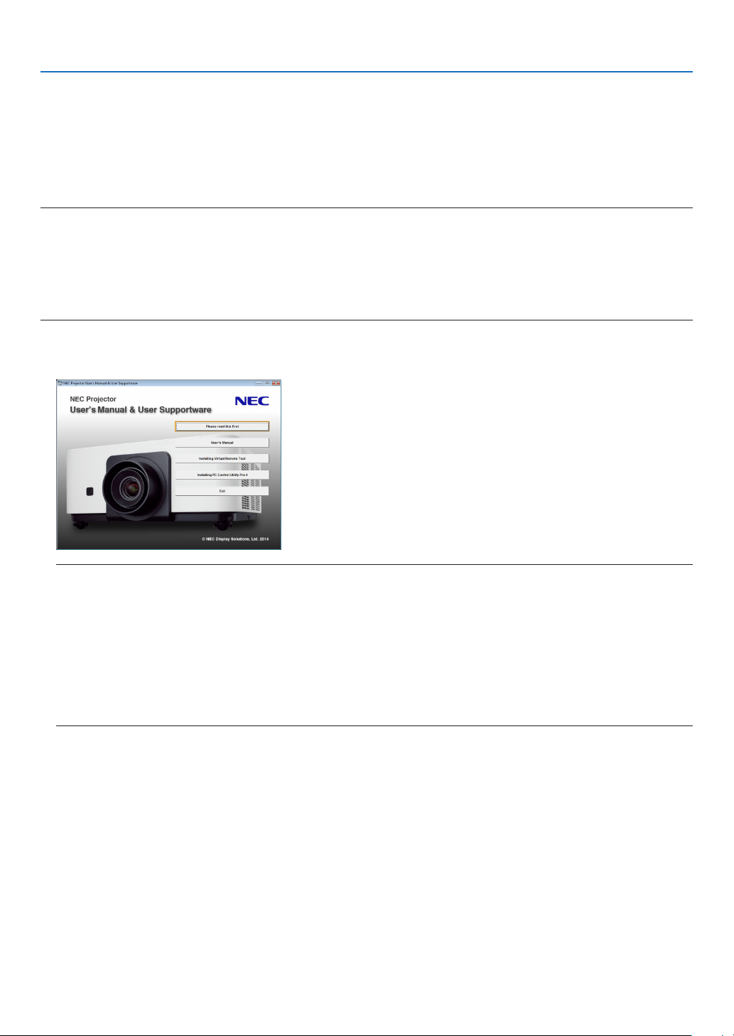
143
8. User Supportware
❷ Installing Software Program
Installation for Windows software
ThesoftwareprogramsexceptPCControlUtilityPro5supportWindows8.1,Windows8,Windows7,WindowsVista,
andWindowsXP.
NOTE:
• Toinstalloruninstalleachsoftwareprogram,theWindowsuseraccountmusthave“Administrator”privilege(Windows8.1,
Windows8,Windows7,WindowsVista)or“ComputerAdministrator”privilege(WindowsXP).
• Exitallrunningprogramsbeforeinstallation.Ifanotherprogramisrunning,theinstallationmaynotbecompleted.
• TorunVirtualRemoteToolorPCControlUtilityPro4onWindows8.1,Windows8,WindowsXPHomeEdition,andWindows
XPProfessional,“Microsoft.NETFrameworkVersion2.0”isrequired.TheMicrosoft.NETFrameworkVersion2.0,3.0or3.5is
availablefromMicrosoft’swebpage.Downloadandinstallitonyourcomputer.
1 InserttheaccompanyingNECProjectorCD-ROMintoyourCD-ROMdrive.
Themenuwindowwillbedisplayed.
TIP:
Ifthemenuwindowwillnotbedisplayed,trythefollowingprocedure.
ForWindows7
1. Click“start”onWindows.
2. Click“AllPrograms”→ “Accessories” → “Run”.
3. Type your CD-ROM drive name (example:“Q:\”) and“LAUNCHER.EXE” in“Name”. (example: Q:\
LAUNCHER.EXE)
4. Click“OK”.
Themenuwindowwillbedisplayed.

144
8. User Supportware
2 Clickasoftwareprogramyouwishtoinstallonthemenuwindow.
Theinstallationwillstart.
• Followtheinstructionsontheinstallerscreenstocompletetheinstallation.
TIP:
UninstallingaSoftwareProgram
Preparation:
Exitthesoftwareprogrambeforeuninstalling.Touninstall thesoftwareprogram,theWindowsuseraccount must
have“Administrator”privilege(Windows8.1,Windows8,Windows7,andWindowsVista)or“ComputerAdministra-
tor”privilege(WindowsXP).
•ForWindows8.1/Windows8/Windows7/WindowsVista
1 Click“Start”andthen“ControlPanel”.
TheControlPanelwindowwillbedisplayed.
2 Click“Uninstallaprogram”under“Programs”
The“ProgramsandFeatures”windowwillbedisplayed.
3 Selectthesoftwareprogramandclickit.
4 Click“Uninstall/Change”or“Uninstall”.
•Whenthe“UserAccountControl”windowsisdisplayed,click“Continue”.
Followtheinstructionsonthescreenstocompletetheuninstallation.
•ForWindowsXP
1 Click“Start”andthen“ControlPanel”.
TheControlPanelwindowwillbedisplayed.
2 Double-click “Add / Remove Programs”.
TheAdd/RemoveProgramswindowwillbedisplayed.
3 Clickthesoftwareprogramfromthelistandthenclick“Remove”.
Followtheinstructionsonthescreenstocompletetheuninstallation.

145
8. User Supportware
Using on Mac OS
Step 1: Install PC Control Utility Pro 5 on the computer.
1. InserttheaccompanyingNECProjectorCD-ROMinyourMacCD-ROMdrive.
TheCD-ROMiconwillbedisplayedonthedesktop.
2. Double-clicktheCD-ROMicon.
TheCD-ROMwindowwillbedisplayed.
3. Double-clickthe“MacOSX”folder.
4. Double-click“PCControlUtilityPro5.pkg”.
Theinstallerwillstart.
5. Click“Next”.
“ENDUSERLICENSEAGREEMENT”screenwillbedisplayed.
6. Read“ENDUSERLICENSEAGREEMENT”andclick“Next”.
Theconrmationwindowwillbedisplayed
7. Click“Iacceptthetermsinthelicenseagreement”.
Followtheinstructionsontheinstallerscreenstocompletetheinstallation.
TIP:
•Uninstallingasoftwareprogram
1. Putthe“PCControlUtilityPro5”foldertotheTrashicon.
2. PutthecongurationleofPCControlUtilityPro5totheTrashicon.
• ThecongurationleofPCControlUtilityPro5islocatedin“/Users/<yourusername>/ApplicationData/NEC
ProjectorUserSupportware/PCControlUtilityPro5”.
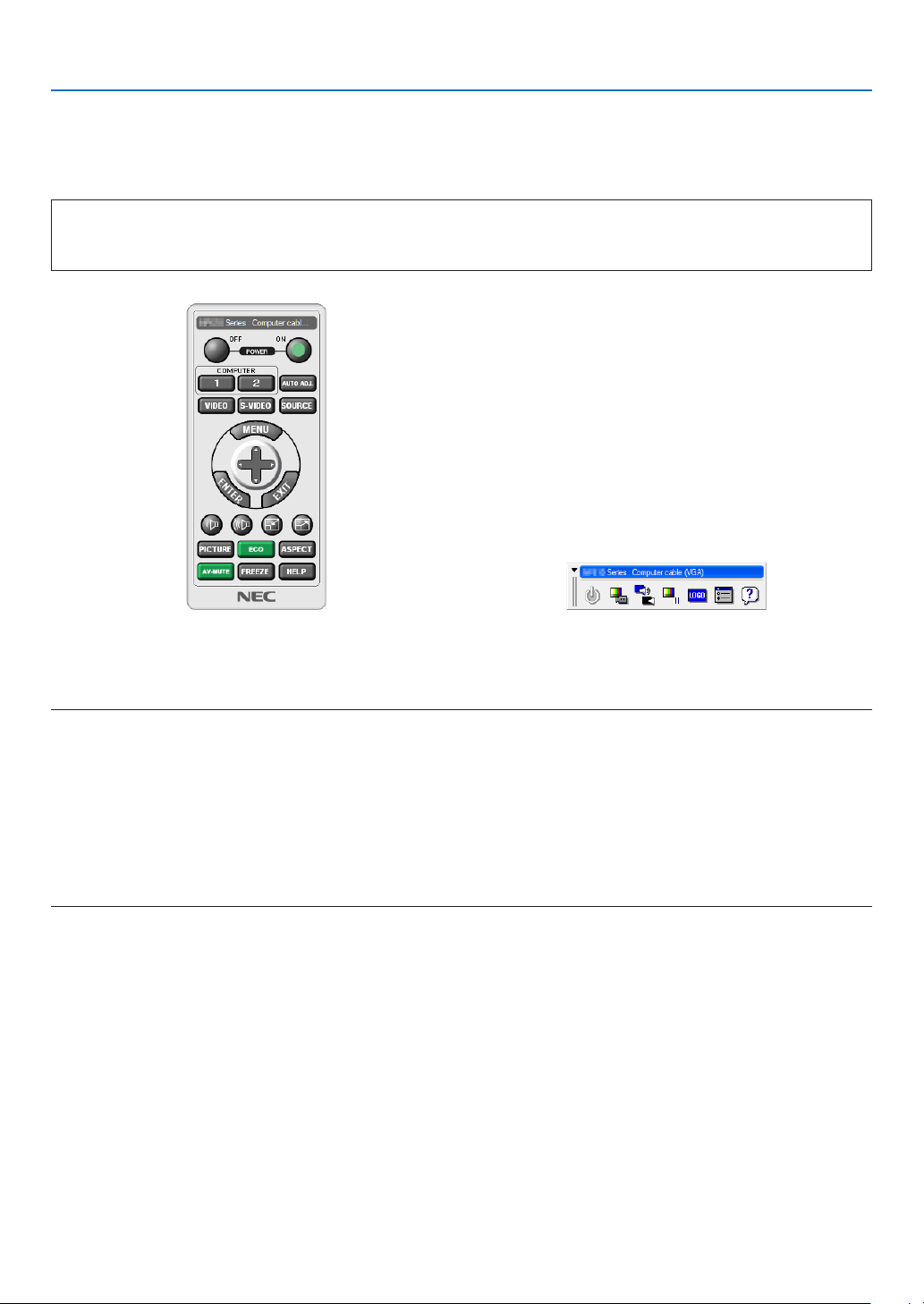
146
8. User Supportware
❸ Operating the Projector Via the LAN (Virtual Remote Tool)
Thiswillhelpyouperformoperationssuchasprojector’spoweronoroffandsignalselectionviaaLANconnection.It
isalsousedtosendanimagetotheprojectorandregisteritasthelogodataoftheprojector.Afterregisteringit,you
canlockthelogotopreventitfromchanging.
Control Functions
PowerOn/Off,signalselection,picturefreeze,picturemute,audiomute,Logotransfertotheprojector,andremote
controloperationonyourPC.
VirtualRemotescreen
RemoteControlWindow Toolbar
ThissectionprovidesanoutlineofpreparationforuseofVirtualRemoteTool.
ForinformationonhowtouseVirtualRemoteTool,seeHelpofVirtualRemoteTool.(→page148)
NOTE:
• Logodata(graphics)thatcanbesenttotheprojectorwithVirtualRemoteToolhasthefollowingrestrictions:
(OnlyviaserialorLANconnection)
* Filesize:Within256kilobytes
* Imagesize:Withintheresolutionoftheprojector
* Fileformat:PNG(Fullcolor)
• Logodata(image)sentusingtheVirtualRemoteToolwillbedisplayedinthecenterwiththesurroundingareainblack.
• Toputthedefault“NEClogo”backinthebackgroundlogo,youneedtoregisteritasthebackgroundlogobyusingtheimagele
(PX602UL-WH/PX602UL-BK:\Logo\NEC_logo2011_WUXGA.png,PX602WL-WH/PX602WL-BK:\Logo\NEC_logo2011_1280x800.
png)includedonthesuppliedNECProjectorCD-ROM.
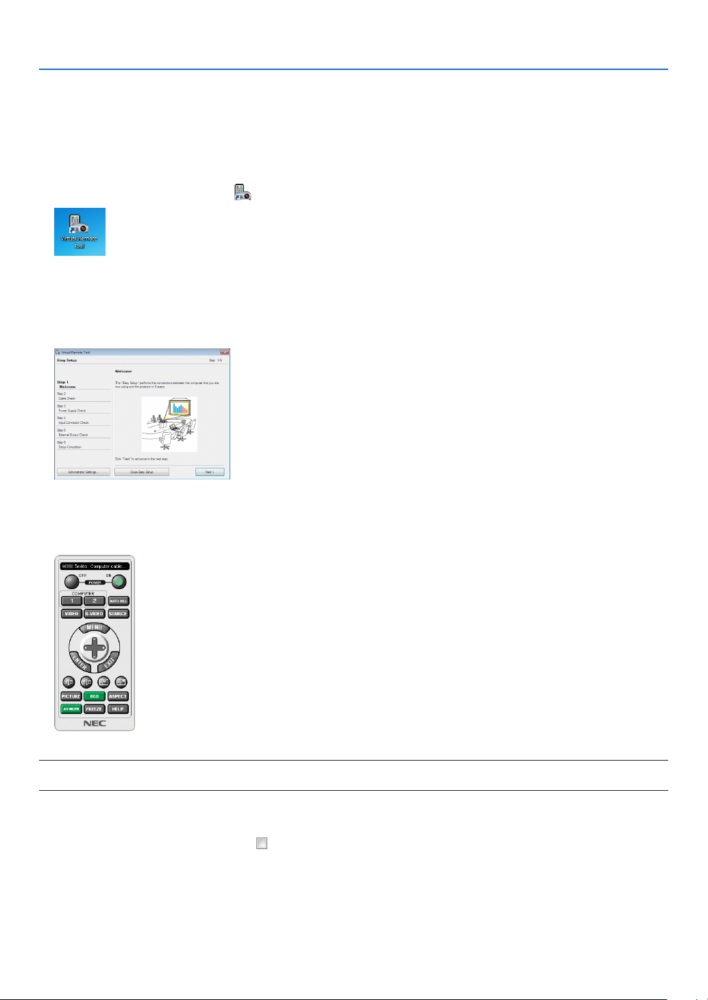
147
8. User Supportware
Connect the projector to a LAN.
ConnecttheprojectortotheLANbyfollowingtheinstructionsin“ConnectingtoaWiredLAN”(→page133)and“10.
ControllingtheProjectorbyUsinganHTTPBrowser”(→page42)
Start Virtual Remote Tool
Start using the shortcut icon
• Double-clicktheshortcuticon on the Windows Desktop.
Start from the Start menu
• Click[Start]→[AllPrograms]or[Programs]→[NECProjectorUserSupportware]→[VirtualRemoteTool]
→[VirtualRemoteTool].
WhenVirtualRemoteToolstartsforthersttime,“EasySetup”windowwillbedisplayed.
The“EasySetup”featureisnotavailableonthismodel.Click“CloseEasySetup”.
Closingthe“EasySetup”windowwilldisplaythe“ProjectorList”window.
Selectyourprojectoryouwishtoconnect.ThiswilldisplaytheVirtualRemotescreen.
NOTE:
• When[NORMAL]isselectedfor[STANDBYMODE]fromthemenu,theprojectorcannotbeturnedonvianetworkconnection.
TIP:
• TheVirtualRemoteToolscreen(orToolbar)canbedisplayedwithoutdisplaying“EasySetup”window.
Todoso,clicktoplaceacheckmarkfor“ DonotuseEasySetupnexttime”onthescreen.
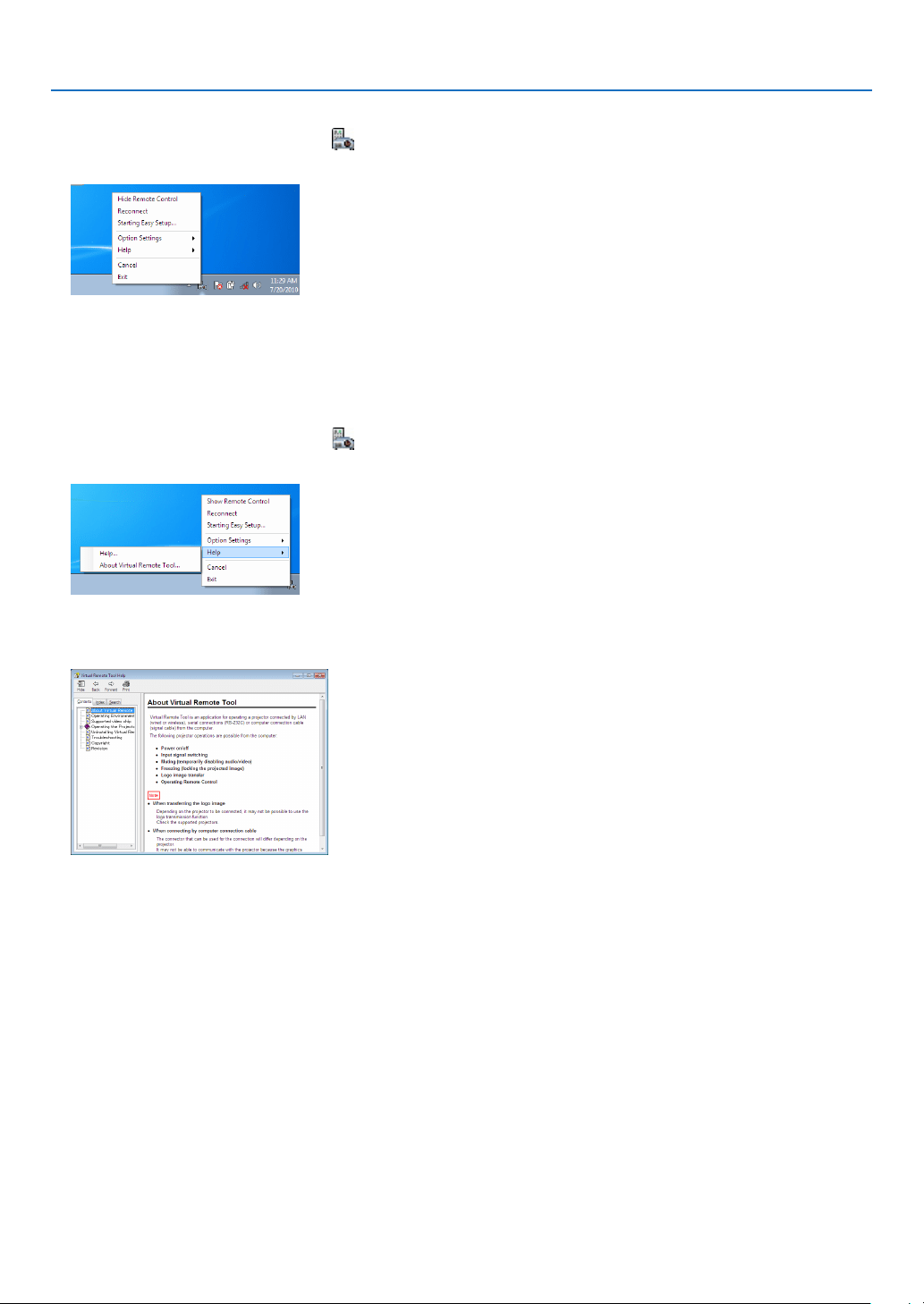
148
8. User Supportware
ExitingVirtualRemoteTool
1 ClicktheVirtualRemoteToolicon on the Taskbar.
Thepop-upmenuwillbedisplayed.
2 Click“Exit”.
TheVirtualRemoteToolwillbeclosed.
ViewingthehelpleofVirtualRemoteTool
•Displayingthehelpleusingthetaskbar
1 ClicktheVirtualRemoteToolicon onthetaskbarwhenVirtualRemoteToolisrunning.
Thepop-upmenuwillbedisplayed.
2. Click“Help”.
TheHelpscreenwillbedisplayed.
•DisplayingthehelpleusingtheStartMenu.
1. Click“Start”.“Allprograms”or“Programs”.“NECProjectorUserSupportware”.“VirtualRemoteTool”.and
then“VirtualRemoteToolHelp”inthisorder.
TheHelpscreenwillbedisplayed.
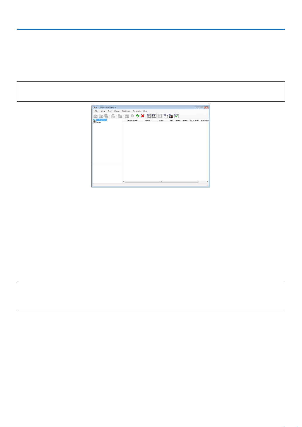
149
8. User Supportware
❹
Controlling the Projector over a LAN (PC Control Utility Pro 4/
Pro 5)
Usingtheutilitysoftware“PCControlUtilityPro4”or“PCControlUtilityPro5”includedonthecompanionNECPro-
jectorCD-ROM,theprojectorcanbecontrolledfromacomputeroveraLAN.
PCControlUtilityPro4isaprogramcompatiblewithWindows.(→thispage)
PCControlUtilityPro5isaprogramcompatiblewithMacOS.(→page152)
Control Functions
PowerOn/Off,signalselection,picturefreeze,picturemute,audiomute,adjusting,errormessagenotication,event
schedule.
ScreenofPCControlUtilityPro4
ThissectionprovidesanoutlineofpreparationforuseofPCControlUtilityPro4/Pro5.Forinformationonhowtouse
PCControlUtilityPro4/Pro5,seeHelpofPCControlUtilityPro4/Pro5.(→page151,152)
Step1:InstallPCControlUtilityPro4/Pro5onthecomputer.
Step2:ConnecttheprojectortoaLAN.
Step3:StartPCControlUtilityPro4/Pro5.
TIP:
• PCControlUtilityPro4canbeusedwithaserialconnection.
Using on Windows
Step 1: Install PC Control Utility Pro 4 on the computer
NOTE:
• Toinstalloruninstalltheprogram,theWindowsuseraccountmusthave[Administrator]privilege(Windows8.1,Windows8,
Windows7,WindowsVistaandWindowsXP)
• Exitallrunningprogramsbeforeinstallation.Ifanotherprogramisrunning,theinstallationmaynotbecompleted.
1 InserttheaccompanyingNECProjectorCD-ROMintoyourCD-ROMdrive.
Themenuwindowwillbedisplayed.
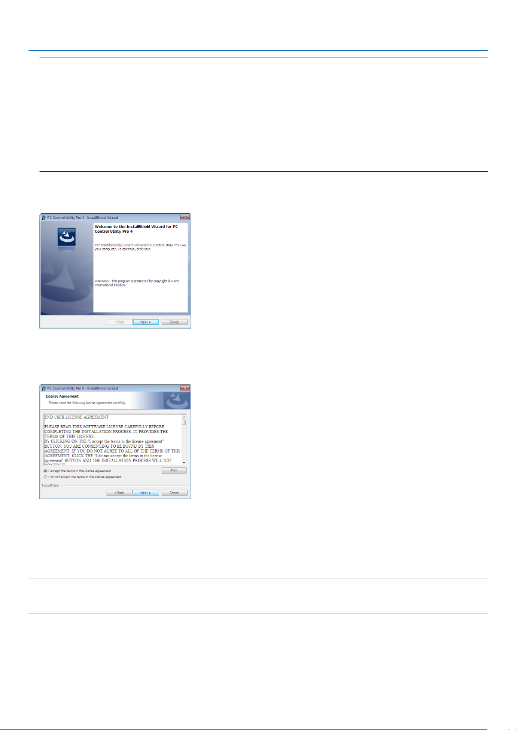
150
8. User Supportware
TIP:
Ifthemenuwindowwillnotbedisplayed,trythefollowingprocedure.
ForWindows7:
1. Click“start”onWindows.
2. Click“AllPrograms”→ “Accessories” → “Run”.
3. Type your CD-ROM drive name (example:“Q:\”) and“LAUNCHER.EXE” in“Name”. (example: Q:\
LAUNCHER.EXE)
4. Click“OK”.
themenuwindowwillbedisplayed.
2 Click“PCControlUtilityPro4”onthemenuwindow.
Theinstallationwillstart.
Whentheinstallationiscomplete,theWelcomewindowwillbedisplayed.
3 Click“Next”.
“ENDUSERLICENSEAGREEMENT”screenwillbedisplayed.
Read“ENDUSERLICENSEAGREEMENT”carefully.
4 Ifyouagree,click“Iacceptthetermsinthelicenseagreement”andthenclick“Next”.
• Followtheinstructionsontheinstallerscreenstocompletetheinstallation.
• Whentheinstallationiscomplete,youwillreturntothemenuwindow.
TIP:
•UninstallingPCControlUtilityPro4
TouninstallPCControlUtilityPro4,dothesameproceduresstatedasin“UninstallingaSoftwareProgram”.(→ page 144, 145)

151
8. User Supportware
Step 2: Connect the projector to a LAN.
ConnecttheprojectortotheLANbyfollowingtheinstructionsin“ConnectingtoaWiredLAN”(→page133)and“10.
ControllingtheProjectorbyUsinganHTTPBrowser”(→page42)
Step 3: Start PC Control Utility Pro 4
Click“Start”→“Allprograms”or“Programs”→“NECProjectorUserSupportware”→“PCControlUtilityPro4”→
“PCControlUtilityPro4”.
NOTE:
• FortheSchedulefunctionofthePCControlutilityPro4towork,youmusthaveyourcomputerrunningandnotinstandby/
sleepmode.Select“PowerOptions”fromthe“ControlPanel”inWindowsanddisableitsstandby/sleepmodebeforerunningthe
scheduler.
[Example]ForWindows7:
Select“ControlPanel”→“SystemandSecurity”→“PowerOptions”→“Changewhenthecomputersleeps”→“Putthecomputer
tosleep”→“Never”.
NOTE:
• When[NORMAL]isselectedfor[STANDBYMODE]fromthemenu,theprojectorcannotbeturnedonviathenetwork(wiredLAN)
connection.
TIP:
ViewingtheHelpofPCControlUtilityPro4
• DisplayingtheHelpleofPCControlUtilityPro4whileitisrunning.
Click“Help(H)”→“Help(H)…”ofwindowofPCControlUtilityPro4inthisorder.
Thepop-upmenuwillbedisplayed.
• DisplayingthehelpleusingtheStartMenu.
Click“Start”→“Allprograms”or“Programs”→“NECProjectorUserSupportware”→“PCControlUtilityPro4”→
“PCControlUtilityPro4Help”.
TheHelpscreenwillbedisplayed.

152
8. User Supportware
Using on Mac OS
Step 1: Install PC Control Utility Pro 5 on the computer
1. InserttheaccompanyingNECProjectorCD-ROMinyourMacCD-ROMdrive.
TheCD-ROMiconwillbedisplayedonthedesktop.
2. Double-clicktheCD-ROMicon.
TheCD-ROMwindowwillbedisplayed.
3. Double-clickthe“MacOSX”folder.
4. Double-click“PCControlUtilityPro5.pkg”.
Theinstallerwillstart.
5. Click“Next”.
“ENDUSERLICENSEAGREEMENT”screenwillbedisplayed.
6. Read“ENDUSERLICENSEAGREEMENT”andclick“Next”.
Theconrmationwindowwillbedisplayed
7. Click“Iacceptthetermsinthelicenseagreement”.
Followtheinstructionsontheinstallerscreenstocompletetheinstallation.
Step 2: Connect the projector to a LAN
ConnecttheprojectortotheLANbyfollowingtheinstructionsin“ConnectingtoaWiredLAN”(→page133)and“10.
ControllingtheProjectorbyUsinganHTTPBrowser”(→page42)
Step 3: Start PC Control Utility Pro 5
1. OpenyourApplicationsfolderinMacOS.
2. Clickthe“PCControlUtilityPro5”folder.
3. Clickthe“PCControlUtilityPro5”icon.
PCControlUtilityPro5willstart.
NOTE:
• FortheSchedulefunctionofthePCControlutilityPro5towork,youmusthaveyourcomputerrunningandnotinsleepmode.
Select“EnergySaver”fromthe“SystemPreferences”inMacanddisableitssleepmodebeforerunningthescheduler.
• When[NORMAL]isselectedfor[STANDBYMODE]fromthemenu,theprojectorcannotbeturnedonviathenetwork(wiredLAN)
connection.
TIP:
ViewingtheHelpofPCControlUtilityPro5
•DisplayingtheHelpleofPCControlUtilityPro5whileitisrunning.
• Fromthemenubar,click“Help”→ “Help” in this order.
TheHelpscreenwillbedisplayed.
•DisplayingtheHelpusingtheDock
1. Open “Application Folder” in Mac OS.
2. Clickthe“PCControlUtilityPro5”folder.
3. Clickthe“PCControlUtilityPro5Help”icon.
TheHelpscreenwillbedisplayed.

153
9. Appendix
❶ Throw distance and screen size
Thisprojectorcanbeusedwith3kindsofoptionallenses(soldseparately).Thechartbelowshowscompatiblelenses
accordingtotheprojectormodel.Refertotheinformationonthispageandusealenssuitedfortheinstallationenvi-
ronment(screensizeandthrowdistance).Forinstructionsonmountingthelens,seepage121.
Lens(model)
Projector(modelname) NP34ZL NP35ZL NP36ZL NP37ZL
PX602UL-WH/PX602UL-BK Ye s Ye s No Ye s
PX602WL-WH/PX602WL-BK Ye s Ye s Ye s Ye s
Yes=canbeused,No=cannotbeused
Lens types and throw distance
PX602UL-WH/PX602UL-BK
Screensize Lensmodelname
NP34ZL NP35ZL NP37ZL
inch m inch m inch m
50"
40-51 1.0-1.3 51-64 1.3-1.7 63-123 1.6-3.2
60" 48-62 1.2 - 1.6 62-77 1.6 - 2.0 76-148 2.0-3.8
80" 64-83 1.7-2.1 83-104 2.1-2.7 103-198 2.6-5.1
100" 81-104 2.1 - 2.6 104-130 2.7-3.3 129-248 3.3-6.3
120" 97-125 2.5-3.2 124-156 3.2-4.0 155-298 4.0-7.6
150" 122-157 3.1-4.0 156-195 4.0-5.0 194-373 4.9-9.5
200" 163-209 4.1-5.3 208-261 5.3-6.6 260-498 6.6-12.7
240" 195-251 5.0-6.4 250-313 6.4-8.0 312-598 7.9-15.2
300" 244-314 6.2-7.9 313-392 7.9-10.0 391-748 9.9-19.0
TIP
Calculationofthethrowdistancefromthescreensize
NP34ZLlensthrowdistance(inch/m)=H×0.96toH×1.23:40"/1.0m(min.)to314"/7.9m(max.)
NP35ZLlensthrowdistance(inch/m)=H×1.23toH×1.54:51"/1.3m(min.)to392"/10.0m(max.)
NP37ZLlensthrowdistance(inch/m)=H×1.53toH×2.94:63"/1.6m(min.)to748"/19.0m(max.)
“H”(Horizontal)referstothescreenwidth.
*Figuresdifferbyseveral%withthetableabovebecausethecalculationisapproximate.
Ex.:Throwdistancewhenprojectingona150"screenwiththePX602UL-WH/PX602UL-BKusingtheNP35ZLlens:
Accordingtothe“ScreenSize(forreference)”table(→ page 155),H(screenwidth)=127.2"/323.1cm.
Thethrowdistanceis127.2"/323.1cm×1.23to127.2"/323.1cm×1.54=156.5"/397.4cmto195.9"/497.6cm(becauseofthe
zoomlens).

154
9. Appendix
PX602WL-WH/PX602WL-BK
Screensize Lensmodelname
NP34ZL NP35ZL/NP36ZL NP37ZL
inch m inch m inch m
50"
42-54 1.1 - 1.4 54-68 1.4-1.7 67-129 1.7-3.3
60" 51-65 1.3-1.7 65-81 1.7-2.1 80-155 2.1 - 4.0
80"
68-87 1.7-2.2 87-109 2.2-2.8 108-208 2.8-5.3
100" 85-109 2.2-2.8 109-136 2.8-3.5 135-260 3.5-6.6
120" 102-131 2.6-3.3 131-164 3.3-4.2 163-313 4.2-8.0
150" 128-164 3.3-4.2 164-205 4.2-5.2 204-392 5.2-10.0
200" 171-219 4.4-5.6 219-274 5.6-6.9 273-523 6.9-13.3
240" 206-263 5.2-6.7 263-329 6.7-8.3 328-628 8.3-15.9
300" 257-330 6.5-8.3 330-411 8.3-10.4 411-786 10.4-19.9
TIP
Calculationofthethrowdistancefromthescreensize
NP34ZLlensthrowdistance(inch/m)=H×1.01toH×1.29:42"/1.1m(min.)to330"/8.3m(max.)
NP35ZL/NP36ZLlensthrowdistance(inch/m)=H×1.29toH×1.61:54"/1.4m(min.)to411"/10.4m(max.)
NP37ZLlensthrowdistance(inch/m)=H×1.61toH×3.08:67"/1.7m(min.)to786"/19.9m(max.)
“H”(Horizontal)referstothescreenwidth.
*Figuresdifferbyseveral%withthetableabovebecausethecalculationisapproximate.
Ex.:Throwdistancewhenprojectingona150"screenwiththePX602WL-WH/PX602WL-BKusingtheNP36ZLlens:
Accordingtothe“ScreenSize(forreference)”table(→ page 155),H(screenwidth)=127.2"/323.1cm.
Thethrowdistanceis127.2"/323.1cm×1.29to127.2"/323.1cm×1.61=164.1"/416.8cmto204.8"/520.2cm(becauseofthe
zoomlens).
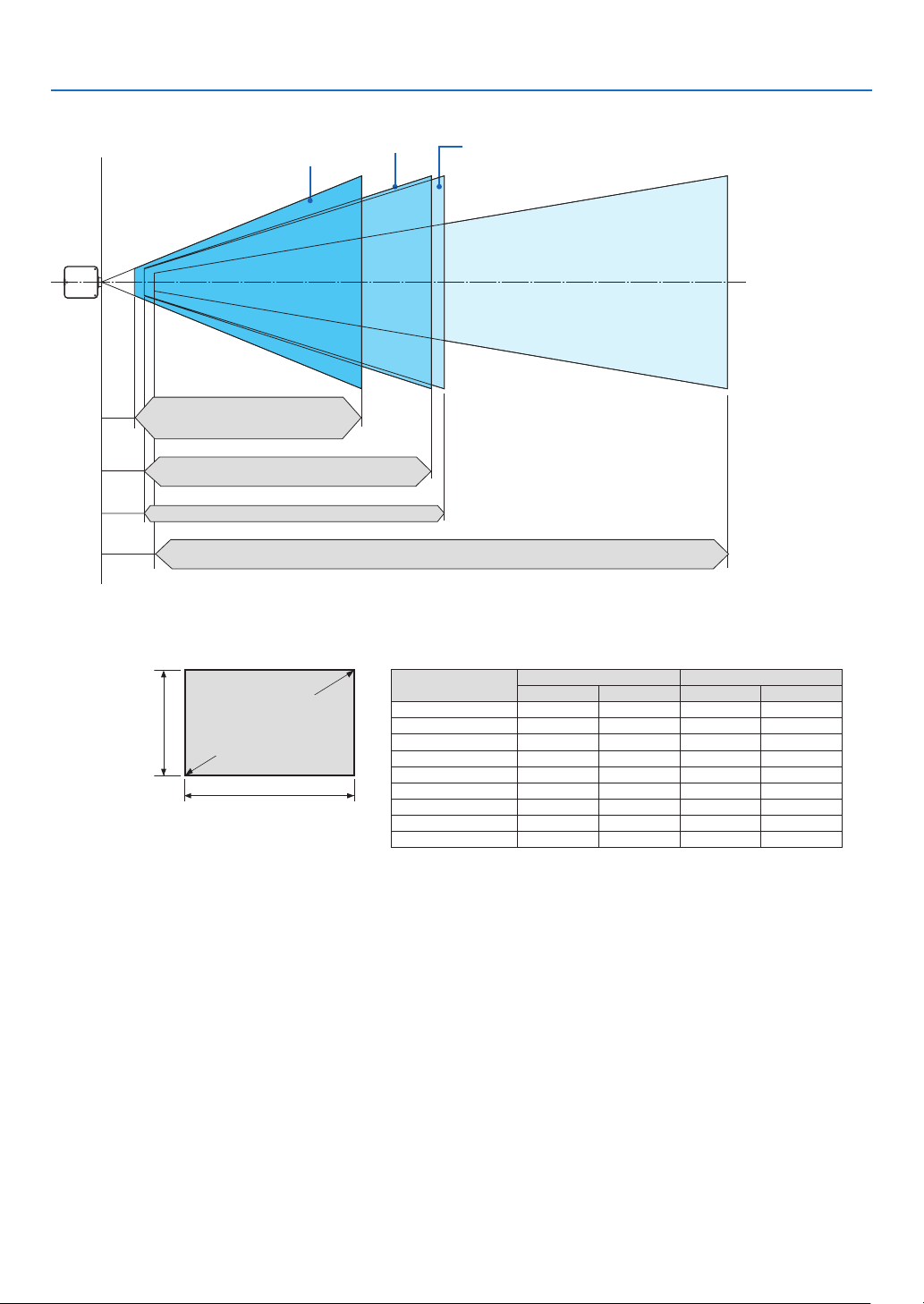
155
9. Appendix
Projectionrangeforthedifferentlenses
50-300"
50-300"
50-300"
50-300"
NP34ZL
PX602UL-WH/PX602UL-BK: 40–314"/1.0–7.9 m
PX602WL-WH/PX602WL-BK: 42–330"/1.1–8.3 m
NP36ZL
PX602WL-WH/PX602WL-BK: 54–411"/1.4–10.4 m
PX602UL-WH/PX602UL-BK: 63–748"/1.6–19.0 m
PX602WL-WH/PX602WL-BK: 67–786"/1.7–19.9 m
NP37ZL
PX602UL-WH/PX602UL-BK: 51–392"/1.3–10.0 m
PX602WL-WH/PX602WL-BK: 54–411"/1.4–10.4 m
NP35ZL
Tables of screen sizes and dimensions
Screenheight
Screenwidth
16:10screensize
(diagonal)
Size(inches) Screenwidth Screenheight
(inches) (cm) (inches) (cm)
50 42.4 107.7 26.5 63.7
60 50.9 129.2 31.8 80.8
80 67.8 172.3 42.4 107.7
100 84.8 215.4 53.0 134.6
120 101.8 258.5 63.6 161.5
150 127.2 323.1 79.5 201.9
200 169.6 430.8 106.0 269.2
240 203.5 516.9 127.2 323.1
300 254.4 646.2 159.0 403.9
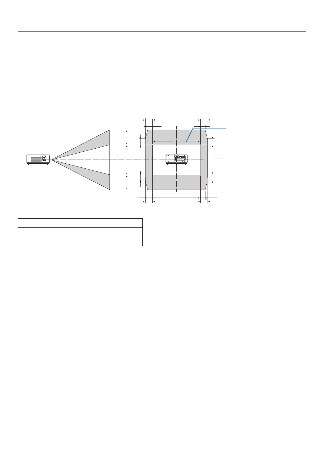
156
9. Appendix
Lens shifting range
ThisprojectorisequippedwithalensshiftfunctionforadjustingthepositionoftheprojectedimagebyusingtheLENS
SHIFTbuttons(→page19).Thelenscanbeshiftedwithintherangeshownbelow.
NOTE:
• Pleasedonotusethelensshiftfunctionwhenprojectingportraitimages.Pleaseuseitwiththelensinthecenter.
Legend:V“Vertical”referstothescreenheightandH“Horizontal”referstothescreenwidth.Thelensshiftrangeis
expressedasaratioofheightandwidth,respectively.
100%V
50%V
50%V
20%V* 20%V*
20%V*
20%V*
100%H
15%H
15%H
15%H
15%H
10%H
10%H 10%H
10%H
Heightofprojectedimage
Widthofprojectedimage
ValueofX
PX602UL-WH/PX602UL-BK 20%V
PX602WL-WH/PX602WL-BK 30%V
* Thelensshiftrangeisthesameforceilinginstallation.
(Example)Whenusingtoprojectona150"screen
Accordingtothe“Tableofscreensizesanddimensions”(→page155),H=127.2"/323.1cm,V=79.5"/201.9cm.
Adjustment range in the vertical direction: the projected image can be moved upwards 0.5 × 79.5"/201.9 cm ≈
39.8"/101cm,downwardsapproximately39.8"/101cm(whenthelensisatthecenterposition).Adjustmentrangein
thehorizontaldirection:theprojectedimagecanbemovedtotheleft0.15×127.2"/323.1cm≈19.1"/48cm,tothe
rightapproximately19.1"/48cm.
* Figuresdifferbyseveral%becausethecalculationisapproximate.
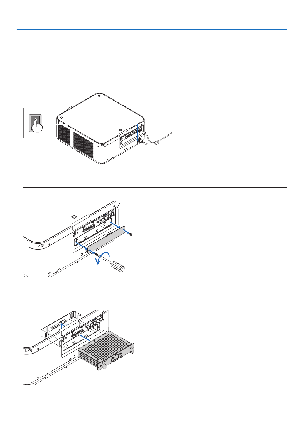
157
9. Appendix
❷ Mounting the Optional Board (sold separately)
CAUTION
Beforemountingorremovingtheoptionalboard,besuretoturnofftheprojector,waitforthefanstostopandturn
offthemainpowerswitch.
Toolneeded:Phillipsscrewdriver(plus-head)
1. Turnoffthemainpowerswitchoftheprojector.
2. LoosenthetwoscrewsontheSLOTcoveroftheterminals.
RemovethetwoscrewsandtheSLOTcover.
NOTE:Keepthetwoscrewsandtheslotcover.
3. Insert the optional board into the slot.
Makesurethattheboardisinsertedintotheslotinthecorrectorientation.
Incorrectorientationmaycausemiscommunicationbetweentheoptionalboardandprojector.
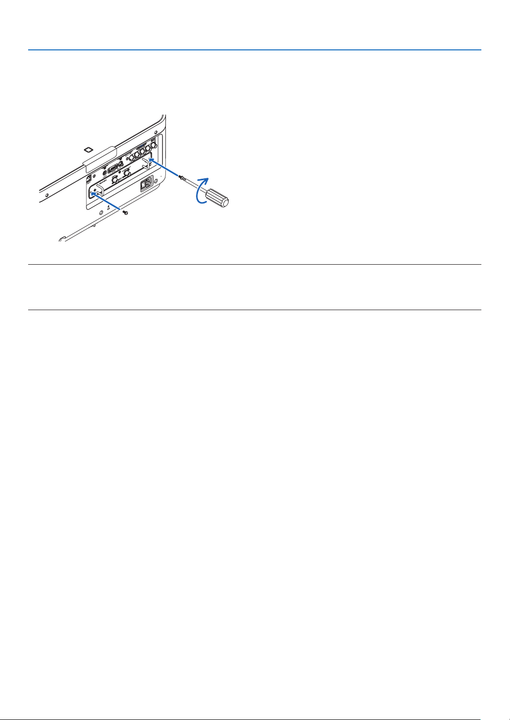
158
9. Appendix
4. Tightenthetwoscrewsonbothsidesoftheslot.
• Besuretotightenthescrews.
Thiswillcompleteinstallationoftheoptionalboard.
Toselecttheoptionalboardsource,selectSLOTastheinput.
NOTE:
• Mountingtheoptionalboardmaycausethefanstoruninthestandbymodeforthepurposeofcoolingdependingontheoptional
board.Thefanspeedmayalsoincreaseinordertocooltheprojectorproperly.Bothoftheseinstancesareconsiderednormal
and not a malfunction of the projector.
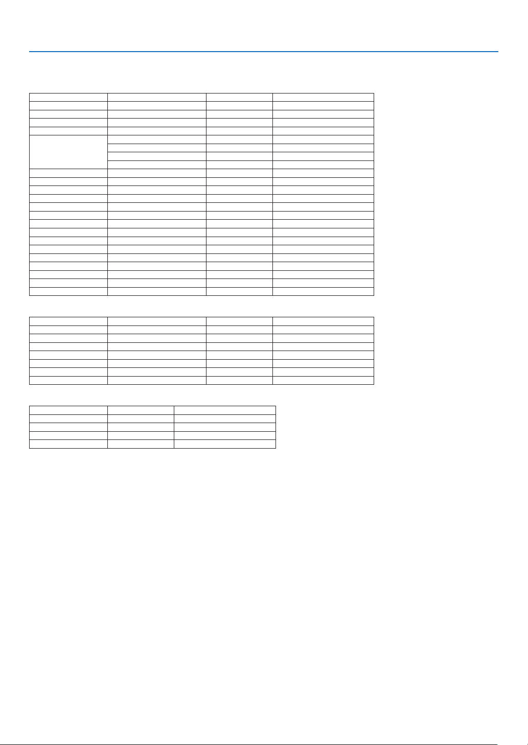
159
9. Appendix
❸ Compatible Input Signal List
Analog Computer Signal
Signal Resolution(dots) AspectRatio RefreshRate(Hz)
VGA 640 × 480 4 : 3 60/72/75/85/iMac
SVGA 800 × 600 4 : 3 56/60/72/75/85/iMac
XGA 1024 × 768 4 : 3 60/70/75/85/iMac
XGA+ 1152 × 864 4 : 3 60/70/75/85
WXGA
1280 × 768 *
1
15 : 9 60
1280 × 800 *
1
16 : 10 60
1360 × 768 *
2
16 : 9 60
1366 × 768 *
2
16 : 9 60
Quad-VGA 1280 × 960 4 : 3 60/75/85
SXGA 1280 × 1024 5 : 4 60/75/85
SXGA+ 1400 × 1050 4 : 3 60/75
WXGA+ 1440 × 900 16 : 10 60
WXGA++ 1600 × 900 16 : 9 60
UXGA 1600 × 1200 *
3
4 : 3 60/65/70/75
WSXGA+ 1680 × 1050 16 : 10 60
WUXGA 1920 × 1200 *
3
16 : 10 60(ReducedBlanking)
2K 2048 × 1080 17 : 9 60
FullHD 1920 × 1080 *
3
16 : 9 60
MAC13" 640 × 480 4 : 3 67
MAC16" 832 × 624 4 : 3 75
MAC19" 1024 × 768 4 : 3 75
MAC21" 1152 × 870 *
4
4 : 3 75
MAC23" 1280 × 1024 5 : 4 65
Component
Signal Resolution(dots) AspectRatio RefreshRate(Hz)
HDTV(1080p) 1920 × 1080 16 : 9 50/60
HDTV(1080i) 1920 × 1080 16 : 9 50/60
HDTV(720p) 1280 × 720 16 : 9 50/60
SDTV(480p) 720 × 480 4:3/16:9 60
SDTV(576p) 720 × 576 4:3/16:9 50
SDTV(480i) 720 × 480 4:3/16:9 60
SDTV(576i) 720 × 576 4:3/16:9 50
CompositeVideo/S-Video
Signal AspectRatio RefreshRate(Hz)
NTSC 4 : 3 60
PA L 4 : 3 50
PAL60 4 : 3 60
SECAM 4 : 3 50

160
9. Appendix
HDMI
Signal Resolution(dots) AspectRatio RefreshRate(Hz)
VGA 640 × 480 4 : 3 60
SVGA 800 × 600 4 : 3 60
XGA 1024 × 768 4 : 3 60
HD 1280 × 720 *
1
16 : 9 60
WXGA
1280 × 768 *
1
15 : 9 60
1280 × 800 *
1
16 : 10 60
1366 × 768 *
2
16 : 9 60
Quad-VGA 1280 × 960 4 : 3 60
SXGA 1280 × 1024 5 : 4 60
SXGA+ 1400 × 1050 4 : 3 60
WXGA+ 1440 × 900 16 : 10 60
WXGA++ 1600 × 900 16 : 9 60
WSXGA+ 1680 × 1050 16 : 10 60
UXGA 1600 × 1200 *
3
4 : 3 60
FullHD 1920 × 1080 *
3
16 : 9 60
WUXGA 1920 × 1200 *
3
16 : 10 60(ReducedBlanking)
2K 2048 × 1080 17 : 9 60
WQHD
iMac27"
2560 × 1440 16 : 9 60
WQXGA 2560 × 1600 16 : 10
60(ReducedBlanking)
4K
3840 × 2160 16 : 9 23.98/24/25/29.97/30
4096 × 2160 17 : 9 24
HDTV(1080p) 1920 × 1080 16 : 9 50/60
HDTV(1080i) 1920 × 1080 16 : 9 50/60
HDTV(720p) 1280 × 720 16 : 9 50/60
SDTV(480i/p) 720/1440 × 480 4:3/16:9 60
SDTV(576i/p) 720/1440 × 576 4:3/16:9 50
HDMI3D
SignalResolution(dots) RefreshRate(Hz) AspectRatio 3DFormat
1920 × 1080p
23.98/24
16 : 9
FramePacking
TopandBottom
50 SideBySide
59.94/60 SideBySide
1920 × 1080i
50
SideBySide
59.94/60 SideBySide
1280 × 720p
50
FramePacking
SideBySide
TopandBottom
59.94/60
FramePacking
SideBySide
TopandBottom
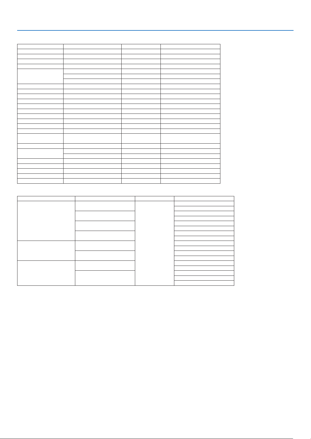
161
9. Appendix
DisplayPort
Signal Resolution(dots) AspectRatio RefreshRate(Hz)
VGA 640 × 480 4 : 3 60
SVGA 800 × 600 4 : 3 60
XGA 1024 × 768 4 : 3 60
HD 1280 × 720 *
1
16 : 9 60
WXGA
1280 × 768 *
1
15 : 9 60
1280 × 800 *
1
16 : 10 60
1366 × 768 *
2
16 : 9 60
Quad-VGA 1280 × 960 4 : 3 60
SXGA 1280 × 1024 5 : 4 60
SXGA+ 1400 × 1050 4 : 3 60
WXGA+ 1440 × 900 16 : 10 60
WXGA++ 1600 × 900 16 : 9 60
WSXGA+ 1680 × 1050 16 : 10 60
UXGA 1600 × 1200 *
3
4 : 3 60
FullHD 1920 × 1080 *
3
16 : 9 60
WUXGA 1920 × 1200 *
3
16 : 10 60(ReducedBlanking)
2K 2048 × 1080 17 : 9 60
WQHD
iMac27"
2560 × 1440 16 : 9 60
WQXGA 2560 × 1600 16 : 10
60(ReducedBlanking)
4K
3840 × 2160 16 : 9 23.98/24/25/29.97/30
4096 × 2160 17 : 9 24
HDTV(1080p) 1920 × 1080 16 : 9 50/60
HDTV(1080i) 1920 × 1080 16 : 9 50/60
HDTV(720p) 1280 × 720 16 : 9 50/60
SDTV(480i/p) 720/1440 × 480 4:3/16:9 60
SDTV(576i/p) 720/1440 × 576 4:3/16:9 50
DisplayPort3D
SignalResolution(dots) RefreshRate(Hz) AspectRatio 3DFormat
1920 × 1080p
23.98/24
16 : 9
SideBySide
TopandBottom
25
SideBySide
TopandBottom
50
SideBySide
TopandBottom
59.94/60
SideBySide
TopandBottom
1920 × 1080i
50
TopandBottom
SideBySide
59.94/60
TopandBottom
SideBySide
1280 × 720p
50
SideBySide
TopandBottom
59.94/60
FramePacking
SideBySide
TopandBottom
*1 NativeresolutiononWXGAmodel(PX602WL-WH/PX602WL-BK)
*2 Theprojectormayfailtodisplaythesesignalscorrectlywhen[AUTO]isselectedfor[ASPECTRATIO]intheon-screenmenu.
Thefactorydefaultis[AUTO]for[ASPECTRATIO].Todisplaythesesignals,select[16:9]for[ASPECTRATIO].
*3 NativeresolutiononWUXGAmodel(PX602UL-WH/PX602UL-BK)
*4 Theprojectormayfailtodisplaythesesignalscorrectlywhen[AUTO]isselectedfor[ASPECTRATIO]intheon-screenmenu.
Thefactorydefaultis[AUTO]for[ASPECTRATIO].Todisplaythesesignals,select[4:3]for[ASPECTRATIO].
• Signalsexceedingtheprojector’sresolutionarehandledwithAdvancedAccuBlend.
• WithAdvancedAccuBlend,thesizeofcharactersandruledlinesmaybeunevenandcolorsmaybeblurred.
• Uponshipment,theprojectorissetforsignalswithstandarddisplayresolutionsandfrequencies,butadjustmentsmayberequired
dependingonthetypeofcomputer.

162
9. Appendix
❹ Specifications
Modelname PX602UL-WH/PX602UL-BK/PX602WL-WH/PX602WL-BK
Method
SingleDLP
®
chip
Specicationsofmainparts
DMDpanel Size PX602UL-WH/PX602UL-BK:0.67"(aspectratio:16:10)
PX602WL-WH/PX602WL-BK:0.65"(aspectratio:16:10)
Pixels
(*1)
PX602UL-WH/PX602UL-BK:2,304,000(1920dots×1200lines)
PX602WL-WH/PX602WL-BK:1,024,000(1280dots×800lines)
Projectionlenses Zoom Powerzoom(zoomrangedependsonlens)
Focus Powerfocus
Lensshifting Powerlensshift
Lightsource 3.5WLaserDiode
Opticaldevice Opticalisolationbydichroicmirror,combiningbydichroicprism
Lightoutput
(*2)
(*3)
6,000lm
Contrastratio
(*2)
(allwhite/allblack) 10,000:1withdynamiccontrast
Screensize(throwdistance) 50"to300"(throwdistancedependsonlens)
Colorreproducibility 10-bitcolorprocessing(approx.1.07billioncolors)
Scanningfrequency Horizontal Analog:15kHz,24to100kHz(24kHzorgreaterforRGBinputs),conformingto
VESAstandards
Digital:15kHz,24to153kHz,conformingtoVESAstandards
Vertical Analog:48Hz,50to85Hz,100,120HzconformingtoVESAstandards
Digital:24,25,30,48Hz,50to85Hz,100,120HzconformingtoVESAstandards
Mainadjustmentfunctions Powerzoom,powerfocus,powerlensshift,inputsignalswitching(HDMI/DisplayPort/
BNC/BNC(CV)/BNC(Y/C)/COMPUTER/HDBaseT/SLOT),autoimageadjustment,pic-
turemaginication,muting(video),poweron/standby,on-screendisplay/selection,etc.
Max.displayresolution(horizontal×
vertical)
Analog:1920×1200(handledwithAdvancedAccuBlend)
Digital:4096×2160(handledwithAdvancedAccuBlend)
Inputsignals
R,G,B,H,V RGB:0.7Vp-p/75Ω
Y:1.0Vp-p/75Ω(withNegativePolaritySync)
Cb,Cr(Pb,Pr):0.7Vp-p/75Ω
H/VSync:4.0Vp-p/TTL
CompositeSync:4.0Vp-p/TTL
SynconG:1.0Vp-p/75Ω(withSync)
Compositevideo 1.0Vp-p/75Ω
S-Video
Y:1.0Vp-p/75Ω
C:286Vp-p/75Ω
Component
Y:1.0Vp-p/75Ω(withSync)
Cb,Cr(Pb,Pr):0.7Vp-p/75Ω
DTV:480i,480p,720p,1080i,1080p(60Hz)
576i,576p,720p,1080i,1080p(50Hz)
DVD:Progressivesignal(50/60Hz)
Input/outputterminals
Computer/Com-
ponent
Videoinput MiniD-Sub15-pin×1,BNCterminal×5
HDMI Videoinput HDMI
®
TerminaltypeA×1
DeepColor(colordepth):8-/10-/12-bitcompatible
Colorimetry:RGB,YcbCr444andYcbCr422compatible
LipSynccompatible,HDCPcompatible
(*4)
,Supports4Kand3D
Videooutput Repeater
Audioinput HDMI:Samplingfrequency–32/44.1/48kHz,Samplingbits–16/20/24bits
HDBaseT Videoinput DeepColor(colordepth):Support8/10/12bits
Colorimetry:SupportRGB,YCbCr444andYCbCr422
SupportLipSync,HDCP
(*4)
,4K,3D
Audioinput Samplingfrequency:32/44.1/48kHz
Samplingbit:16/20/24bit
DisplayPort Videoinput DisplayPort×1
Datarate:2.7Gbps/1.62Gbps
No.lanes:1lane/2lanes/4lanes
Colordepth:6-bit,8-bit,10-bit
Colorimetry:RGB,YcbCr444andYcbCr422compatible
HDCPcompatible
(*4)
Audioinput DisplayPort:Samplingfrequency–32/44.1/48kHz,Samplingbits–16/20/24bits
BNC(CV) Videoinput BNC×1
BNC(Y/C) Videoinput BNC×2
PCcontrolterminal D-Sub9-pin×1

163
9. Appendix
Modelname PX602UL-WH/PX602UL-BK/PX602WL-WH/PX602WL-BK
USBport USBtypeA×1
Ethernet/HDBaseTport RJ-45×1,SupportsBASE-TX
Remoteterminal Stereominijack×1
3DSYNCoutputterminal 5V/10mA,synchronizedsignaloutputfor3Duse
Usageenvironment Operatingtemperature:5to40°C
(*5)
Operatinghumidity:20to80%(withnocondensation)
Storagetemperature:-10to60°C
(*5)
Storagehumidity:20to80%(withnocondensation)
Operatingaltitude:0to3000m/10,000feet
(760to3000m/2500to10,000feet:Set[FANMODE]to[HIGH])
Powersupply 100-240VAC,50/60Hz
Powercon-
sumption
LIGHT
MODE
NORMAL 590W(100-130V)/550W(200-240V)
ECO1 460W(100-130V)/440W(200-240V)
ECO2 280W(100-130V)/270W(200-240V)
STAND-
BY
MODE
NORMAL 0.5W
NETWORK
STANDBY
6.0 W
Ratedinputcurrent 6.8A-2.5A
Externaldimensions 19.1"(width)×7.7"(height)×20.0"(depth)/484.4(width)×195.0(height)×509.0
(depth)mm(notincludingthelenshoodandprotrudingparts)
19.1"(width)×8.5"(height)×22.6"(depth)/484.4(width)×217.0(height)×574.8
(depth)mm(includingthelenshoodandprotrudingparts)
Weight 40.8lbs/18.5kg(notincludinglens)
*1 Effectivepixelsaremorethan99.99%.
*2 Thisisthelightoutputvaluethatresultsfromsettingthe[LIGHTMODE]to[NORMAL]andsettingthe[PRESET]to[HIGH-BRIGHT]
whileusingtheNP35ZLlensforNP-PX602UL-WHJD,orNP36ZLlensforNP-PX602WL-WHJD(soldseparately).
Thelightoutputvalueislowerwhensettingthe[LIGHTMODE]to[ECO1]or[ECO2].([ECO1]:about80%,[ECO2]:about50%).
Ifanyothermodeisselectedasthe[PRESET]mode,thelightoutputvaluemaydropslightly.
*3 CompliancewithISO21118-2005
*4 HDMI
®
(DeepColor,LipSync)withHDCP
WhatisHDCP/HDCPtechnology?
HDCPisanacronymforHigh-bandwidthDigitalContentProtection.HighbandwidthDigitalContentProtection(HDCP)isasystem
forpreventingillegalcopyingofvideodatasentoveraHigh-DenitionMultimediaInterface(HDMI).
IfyouareunabletoviewmaterialviatheHDMIinput,thisdoesnotnecessarilymeantheprojectorisnotfunctioningproperly.With
theimplementationofHDCP,theremaybecasesinwhichcertaincontentisprotectedwithHDCPandmightnotbedisplayed
duetothedecision/intentionoftheHDCPcommunity(DigitalContentProtection,LLC).
Video:DeepColor;8/10/12-bit,LipSync
Audio:LPCM;upto2ch,samplerate32/44.1/48KHz,samplebit;16/20/24-bit
*5 Theupperthresholdofoperatingtemperatureischangeddependsonthealtitude.
0–760m(0–2500feet):5–40°C
760–1500m(2500–5000feet):5–35°C
1500–3000m(5000–10000feet):5–30°C
35to40°C–“Forcedecomode”
• Thesespecicationsandtheproduct’sdesignaresubjecttochangewithoutnotice.
Foradditionalinformationvisit:
US:http://www.necdisplay.com/
Europe:http://www.nec-display-solutions.com/
Global:http://www.nec-display.com/global/index.html
Forinformationonouroptionalaccessories,visitourwebsiteorseeourbrochure.

164
9. Appendix
Optionlens(soldseparately)
OptionlensforPX602UL-WH/PX602UL-BK
NP34ZL Powerlensshift,Powerzoom,Powerfocus
(Throwratio0.96–1.23:1,F2.3–2.57,f=0.55–0.71"/14.03–17.95mm)
NP35ZL Powerlensshift,Powerzoom,Powerfocus
(Throwratio1.23–1.54:1,F2.0–2.32,f=0.71–0.89"/18.07–22.59mm)
NP37ZL Powerlensshift,Powerzoom,Powerfocus
(Throwratio1.53–2.94:1,F2.3–3.39,f=0.89–1.69"/22.56–42.87mm)
OptionlensforPX602WL-WH/PX602WL-BK
NP34ZL Powerlensshift,Powerzoom,Powerfocus
(Throwratio1.01–1.29:1,F2.3–2.57,f=0.55–0.71"/14.03–17.95mm)
NP35ZL Powerlensshift,Powerzoom,Powerfocus
(Throwratio1.29–1.61:1,F2.0–2.32,f=0.71–0.89"/18.07–22.59mm)
NP36ZL Powerlensshift,Powerzoom,Powerfocus
(Throwratio1.29–1.61:1,F2.0–2.32,f=0.71–0.89"/18.07–22.59mm)
NP37ZL Powerlensshift,Powerzoom,Powerfocus
(Throwratio1.61–3.08:1,F2.3–3.39,f=0.89–1.69"/22.56–42.87mm)
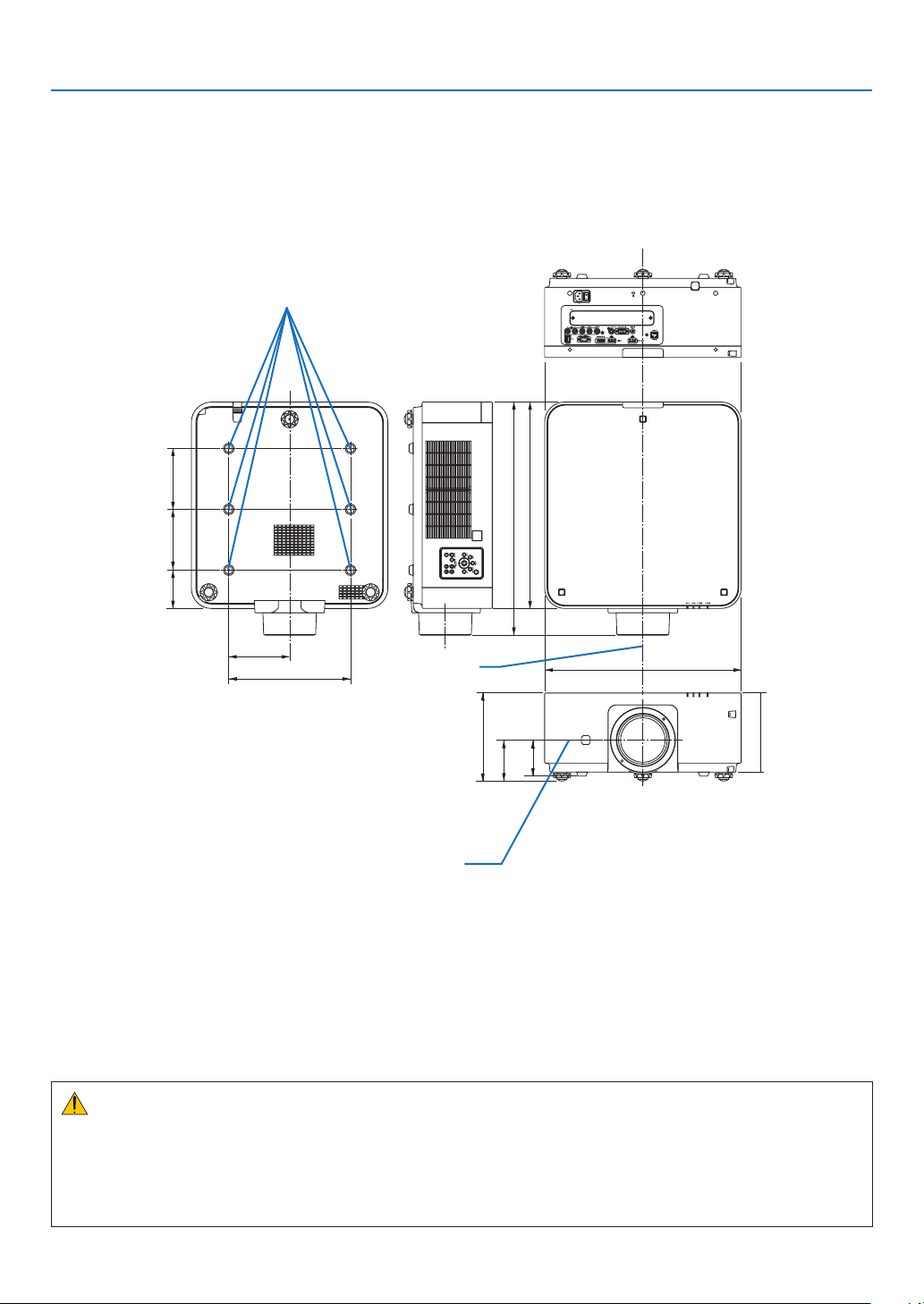
165
9. Appendix
❺ Cabinet Dimensions
Unit:mm(inch)
484.4 (19.1)
150 (5.9)
509 (20)
195 (7.7)
217 (8.5)
101 (4)
89 (3.5)
94.5
(3.7)
150 (5.9) 150 (5.9)
574.8 (22.6)
300 (11.8)
Lenscenter
Lenscenter
6-M4×L8(Max)forCeilingMount*
* ThescrewsspecicationsforCeilingMount:
Screwtype:M4
Maximumscrewlength:8mm(0.31")
Minimumscrewlength:6mm(0.24")
CAUTION:
Donotattempttomounttheprojectoronaceilingyourself.
Theprojectormustbeinstalledbyqualiedtechniciansinordertoensureproperoperationandreducetheriskof
bodilyinjury.
Inaddition,theceilingmustbestrongenoughtosupporttheprojectorandtheinstallationmustbeinaccordance
withanylocalbuildingcodes.Pleaseconsultyourdealerformoreinformation.
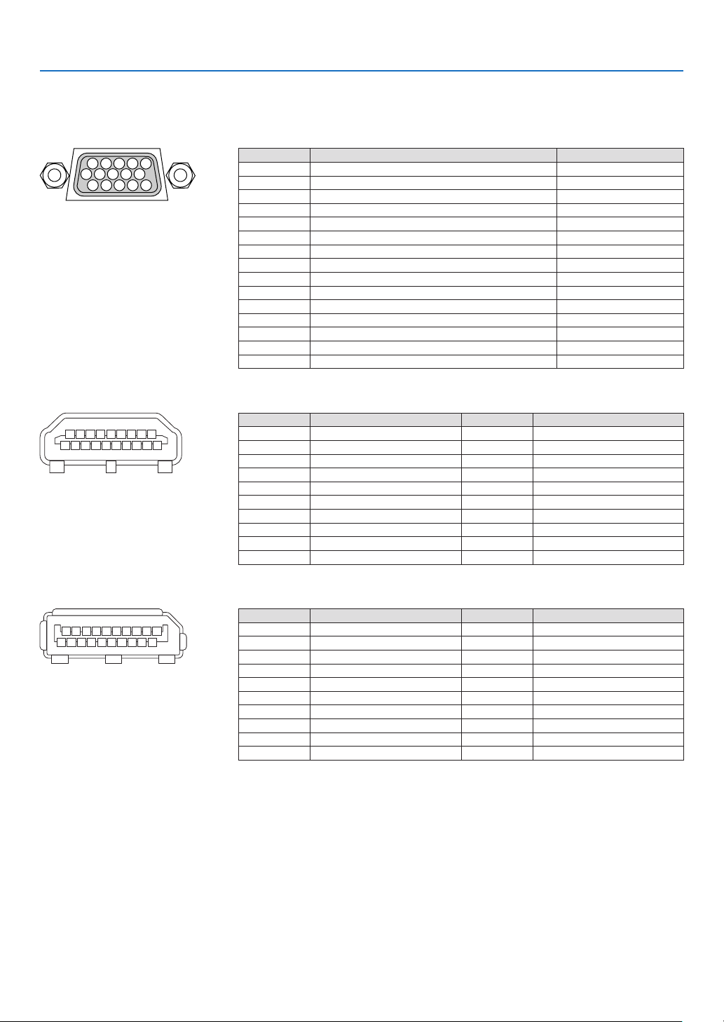
166
9. Appendix
❻ Pin assignments and signal names of main terminals
COMPUTER 1 IN/ Component Input Terminal (Mini D-Sub 15 Pin)
Connection and signal level of each pin
51423
10
11 12 13 14 15
6978
Signal Level
Videosignal:0.7Vp-p(Analog)
Syncsignal:TTLlevel
PinNo. RGBSignal(Analog) YCbCrSignal
1 Red Cr
2
GreenorSynconGreen Y
3 Blue Cb
4 Ground
5 Ground
6
RedGround CrGround
7 GreenGround YGround
8 BlueGround CbGround
9 NoConnection
10 SyncSignalGround
11 NoConnection
12 Bi-directionalDATA(SDA)
13 HorizontalSyncorCompositeSync
14 VerticalSync
15 DataClock
HDMI IN Terminal (Type A)
135791113151719
246810 12 14 16 18
PinNo. Signal PinNo. Signal
1
TMDSData2+ 11 TMDSClockShield
2 TMDSData2Shield 12 TMDSClock−
3 TMDSData2− 13 CEC
4
TMDSData1+ 14 Disconnection
5
TMDSData1Shield 15 SCL
6
TMDSData1− 16 SDA
7
TMDSData0+ 17 DDC/CECgrounding
8 TMDSData0Shield 18 +5Vpowersupply
9 TMDSData0− 19 Hotplugdetection
10 TMDSClock+
DisplayPort IN Terminal
135791113151719
246810 12 14 16 18 20
PinNo. Signal PinNo. Signal
1
Mainlinklane3− 11 Grounding0
2 Grounding3 12 Mainlinklane0+
3 Mainlinklane3+ 13 Conguration1
4 Mainlinklane2− 14 Conguration2
5 Grounding2 15 Supplementarychannel+
6 Mainlinklane2+ 16 Grounding4
7 Mainlinklane1− 17 Supplementarychannel−
8 Grounding1 18 Hotplugdetection
9 Mainlinklane1+ 19 Return
10
Mainlinklane0− 20 +3.3Vpowersupply
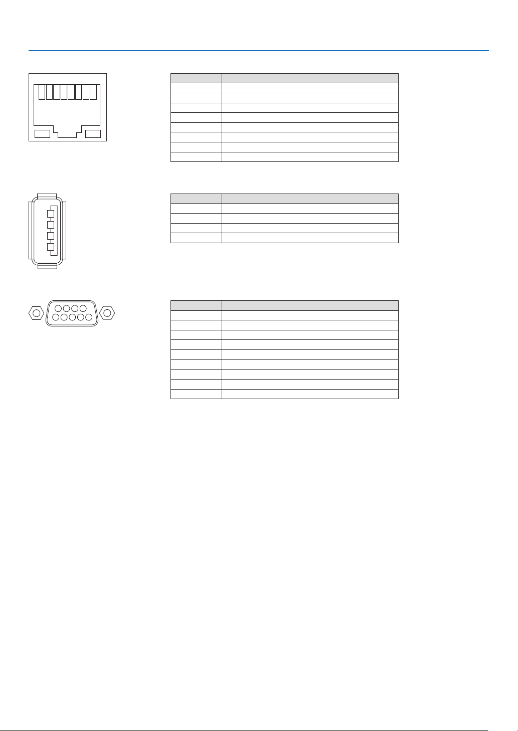
167
9. Appendix
Ethernet/HDBaseT Port (RJ-45)
12345678
PinNo. Signal
1 TxD+/HDBT0+
2 TxD−/HDBT0−
3 RxD+/HDBT1+
4 Disconnection/HDBT2+
5 Disconnection/HDBT2−
6 RxD−/HDBT1−
7 Disconnection/HDBT3+
8 Disconnection/HDBT3−
USB Port (Type A)
1
3
2
4
PinNo. Signal
1 V
BUS
2 D−
3 D+
4 Grounding
PC CONTROL Port (D-Sub 9 Pin)
1234
5
6789
Communications protocol
PinNo. Signal
1 Unused
2
RxD receptiondata
3 TxD transmissiondata
4 Unused
5 Grounding
6 Unused
7
RTS transmissionrequest
8 CTS transmissionallowed
9 Unused

168
9. Appendix
❼ Troubleshooting
Thissectionhelpsyouresolveproblemsyoumayencounterwhilesettinguporusingtheprojector.
Indicator Messages
POWERIndicator
Indicatordisplay Projectorstatus Procedure
Off Powerisoff. –
Flashing
Blue(shortashes) Preparingtoturnpoweron Waitawhile.
Blue(longashes) Offtimer(enabled)
Programtimer(offtimeenabled)
–
Orange(shortashes) Projectorcooling Waitawhile.
Orange(longashes) Programtimer(ontimeenabled) –
Lit Blue
Poweron –
Red Standbymode(NORMAL) –
Orange
Standbymode(NETWORKSTANDBY) –
STATUS Indicator
Indicatordisplay Projectorstatus Procedure
Off
Noproblem,orSTAND-
BYMODE-“NETWORK
STANDBY”
–
Flashing Red
Thelenshoodisnot
xedon,orthesafety
cover(soldseparately)
isnotxedonduringthe
portraitprojection
Checkxing conditions ofthe lens hood and the safety
cover.
Red(cycleof
4timesash)
Fanproblem The cooling fan has stopped turning. Contact an NEC
projectorcustomersupportcenterforrepairs.
Flashing Orange Networkconict It is not possible to connect the projector’s built-in LAN
and wireless LAN simultaneously to the same network.
Toconnecttheprojector’sbuilt-inLANandwirelessLAN
simultaneously,connectthemtodifferentnetworks.
Lit Green STANDBYMODEin
sleepmode*
–
Orange
Buttonhasbeen
pressedwhileprojector
isinkeylockmode
Theprojector’skeysarelocked.Thesettingmustbecan-
celedtooperatetheprojector.(→Page104)
Projector’sIDnumber
andremotecontrol’sID
numberdonotmatch
CheckthecontrolIDs.(→Pages105)
* Sleepmodereferstothestatewherebythefunctionalrestrictionsduetothestandbymodesettingareremoved.

169
9. Appendix
LIGHT Indicator
Indicatordisplay Projectorstatus Procedure
Off
Thelightmoduleis
turnedoff.
–
Lit Green
Lightmodulelit –
TEMP.Indicator
Indicatordisplay Projectorstatus Procedure
Off
Noproblem
Flashing Red(cycles
of2)
Temperatureproblem Thetemperatureprotectorhasbeenactivated.Iftheroom
temperatureishigh,movetheprojectortoacoolplace.If
theproblemstillpersists,contactanNECprojectorcus-
tomersupportcenter.
Lit Orange Highsurroundingtem-
perature(ForcedECO
Mode)
The surrounding temperature is high. Lower the room
temperature.
If the temperature protector is activated
Iftheprojector’sinternaltemperaturerisesabnormally,thelightmoduleturnsoffandthetemperatureindicatorashes
(repeatedlyincyclesof2).
Itmayhappenthattheprojector’stemperatureprotectorissimultaneouslyactivatedandtheprojector’spowerturnsoff.
Ifthishappens,dothefollowing:
- Unplugthepowercordfromthepoweroutlet.
- Ifusinginaplacewherethesurroundingtemperatureishigh,movetheprojectortoadifferent,coolplace.
- Ifthereisdustintheventilationholes,clean.(→page141)
- Waitassuchabout1hourfortheprojector’sinternaltemperaturetolower.

170
9. Appendix
Common Problems & Solutions
(→“POWER/STATUS/LIGHTIndicator”onpage168,169.)
Problem CheckTheseItems
Does not turn on
or shut down
• Checkthatthepowercordispluggedinandthatthepowerbuttonontheprojectorcabinetortheremote
control is on� (→ pages 13, 14)
• Checktoseeiftheprojectorhasoverheated.Ifthereisinsufcientventilationaroundtheprojectororifthe
room where you are presenting is particularly warm, move the projector to a cooler location�
• Thelightmodulemayfailtolight.Waitafullminuteandthenturnonthepoweragain.
• Set[FANMODE]to[HIGH]whenusingtheprojectorataltitudesapproximately760m/2500feetorhigher.
Using the projector at altitudes approximately 760 m/2500 feet or higher without setting to [HIGH] can
cause the projector to overheat and the projector could shut down� If this happens, wait a couple minutes
and turn on the projector� (→ page 97)
If you turn on the projector immediately after the light module is turned off, the fans run without displaying
an image for some time and then the projector will display the image� Wait for a moment�
• Incaseit’shardtothinkthetroubleisnotcausedontheabovementionedconditions,unplugthepower
cord from the outlet� Then wait 5 minutes before plugging it in again� (→ page 24)
Will turn off
• Ensurethatthe[OFFTIMER],[AUTOPOWEROFF]or[PROGRAMTIMER]isoff.(→ page 100, 115)
No picture
• Checkiftheappropriateinputisselected.(→ page 16) If there is still no picture, press the SOURCE button
or one of the source buttons again�
• Ensureyourcablesareconnectedproperly.
• Usemenustoadjustthebrightnessandcontrast.(→ page 76)
• CheckthattheSHUTTER(lensshutter)orAVMUTE(imageoff)buttonsarenotpressed.
• Resetthesettingsoradjustmentstofactorypresetlevelsusingthe[RESET]intheMenu.(→ page 116)
• EnteryourregisteredkeywordiftheSecurityfunctionisenabled.(→ page 35)
• IftheHDMIINortheDisplayPortINsignalcannotbedisplayed,trythefollowing.
- Reinstall your driver for the graphics card built in your computer, or use the updated driver�
For reinstalling or updating your driver, refer to the user guide accompanied with your computer or
graphics card, or contact the support center for your computer manufacturer�
Install the updated driver or OS on your own responsibility�
We are not liable for any trouble and failure caused by this installation�
• SignalsmaynotbesupporteddependingontheHDBaseTtransmissiondevice.IRandRS232Ccannotbe
used in certain cases as well�
• BesuretoconnecttheprojectorandnotebookPCwhiletheprojectorisinstandbymodeandbeforeturning
on the power to the notebook PC�
In most cases the output signal from the notebook PC is not turned on unless connected to the projector
before being powered up�
* If the screen goes blank while using your remote control, it may be the result of the computer’s screen-
saver or power management software�
• Seealsothepage172�
Picture suddenly
becomes dark
• CheckiftheprojectorisintheForcedECOmodebecauseoftoohighambienttemperature.Ifthisisthe
case, lower the internal temperature of the projector by selecting [HIGH] for [FAN MODE]� (→ page 97)
Color tone or hue is
unusual
• Checkifanappropriatecolorisselectedin[WALLCOLOR].Ifso,selectanappropriateoption.(→ page
97)
• Adjust[HUE]in[PICTURE].(→ page 77)
Image isn’t square to
the screen
• Repositiontheprojectortoimproveitsangletothescreen.(→ page 18)
• UsetheKeystonecorrectionfunctiontocorrectthetrapezoiddistortion.(→ page 32)
Picture is blurred
• Adjustthefocus.(→ page 21)
• Repositiontheprojectortoimproveitsangletothescreen.(→ page 18)
• Ensurethat the distancebetween theprojector andscreen is withinthe adjustmentrange ofthe lens.
(→ page 153)
• Hasthelensbeenshiftedbyanamountexceedingtheguaranteedrange?(→ page 156)
• Condensationmayformonthelensiftheprojectoriscold,broughtintoawarmplaceandisthenturned
on� Should this happen, let the projector stand until there is no condensation on the lens�
Image is scrolling
vertically, horizontally
or both
• Checkthecomputer’sresolutionandfrequency.Makesurethattheresolutionyouaretryingtodisplayis
supported by the projector� (→ page 159)
• AdjustthecomputerimagemanuallywiththeHorizontal/Verticalinthe[IMAGEOPTIONS].(→ page 79)

171
9. Appendix
Problem CheckTheseItems
Remote control does
not work
• Installnewbatteries.(→ page 10)
• Makesuretherearenoobstaclesbetweenyouandtheprojector.
• Standwithin22feet(7m)oftheprojector.(→ page 11)
Indicator is lit or
blinking
• SeethePOWER/STATUS/LIGHTIndicator.(→ page 168, 169)
Cross color in RGB
mode
• PresstheAUTOADJ.buttonontheprojectorcabinetortheremotecontrol.(→ page 23)
• Adjustthecomputerimagemanuallywith[CLOCK]/[PHASE]in[IMAGEOPTIONS]inthemenu.(→ page
78)
Formoreinformationcontactyourdealer.

172
9. Appendix
If there is no picture, or the picture is not displayed correctly.
• PoweronprocessfortheprojectorandthePC.
BesuretoconnecttheprojectorandnotebookPCwhiletheprojectorisinstandbymodeandbeforeturningon
thepowertothenotebookPC.
InmostcasestheoutputsignalfromthenotebookPCisnotturnedonunlessconnectedtotheprojectorbefore
beingpoweredup.
NOTE:Youcancheckthehorizontalfrequencyofthecurrentsignalintheprojector’smenuunderInformation.Ifitreads“0kHz”,
thismeansthereisnosignalbeingoutputfromthecomputer.(→ page 117orgotonextstep)
• Enablingthecomputer’sexternaldisplay.
DisplayinganimageonthenotebookPC’sscreendoesnotnecessarilymeanitoutputsasignaltotheprojector.
WhenusingaPCcompatiblelaptop,acombinationoffunctionkeyswillenable/disabletheexternaldisplay.Usu-
ally,thecombinationofthe“Fn”keyalongwithoneofthe12functionkeysgetstheexternaldisplaytocomeon
oroff.Forexample,NEClaptopsuseFn+F3,whileDelllaptopsuseFn+F8keycombinationstotogglethrough
externaldisplayselections.
• Non-standardsignaloutputfromthecomputer
IftheoutputsignalfromanotebookPCisnotanindustrystandard,theprojectedimagemaynotbedisplayed
correctly.Shouldthishappen,deactivatethenotebookPC’sLCDscreenwhentheprojectordisplayisinuse.Each
notebookPChasadifferentwayofdeactivate/reactivatethelocalLCDscreensasdescribedinthepreviousstep.
Refertoyourcomputer’sdocumentationfordetailedinformation.
• ImagedisplayedisincorrectwhenusingaMac
WhenusingaMacwiththeprojector,settheDIPswitchoftheMacadapter(notsuppliedwiththeprojector)ac-
cordingtoyourresolution.Aftersetting,restartyourMacforthechangestotakeaffect.
ForsettingdisplaymodesotherthanthosesupportedbyyourMacandtheprojector,changingtheDIPswitchon
aMacadaptermaybounceanimageslightlyormaydisplaynothing.Shouldthishappen,settheDIPswitchto
the13"xedmodeandthenrestartyourMac.Afterthat,restoretheDIPswitchestoadisplayablemodeandthen
restarttheMacagain.
NOTE:AVideoAdaptercablemanufacturedbyAppleComputerisneededforaMacBookwhichdoesnothaveaminiD-Sub
15-pin terminal.
• MirroringonaMacBook
* WhenusingtheprojectorwithaMacBook,outputmaynotbesetto1024×768unless“mirroring”isoffonyour
MacBook.Refertoowner’smanualsuppliedwithyourMaccomputerformirroring.
• FoldersoriconsarehiddenontheMacscreen
Foldersoriconsmaynotbeseenonthescreen.Shouldthishappen,select[View]→[Arrange]fromtheApple
menuandarrangeicons.
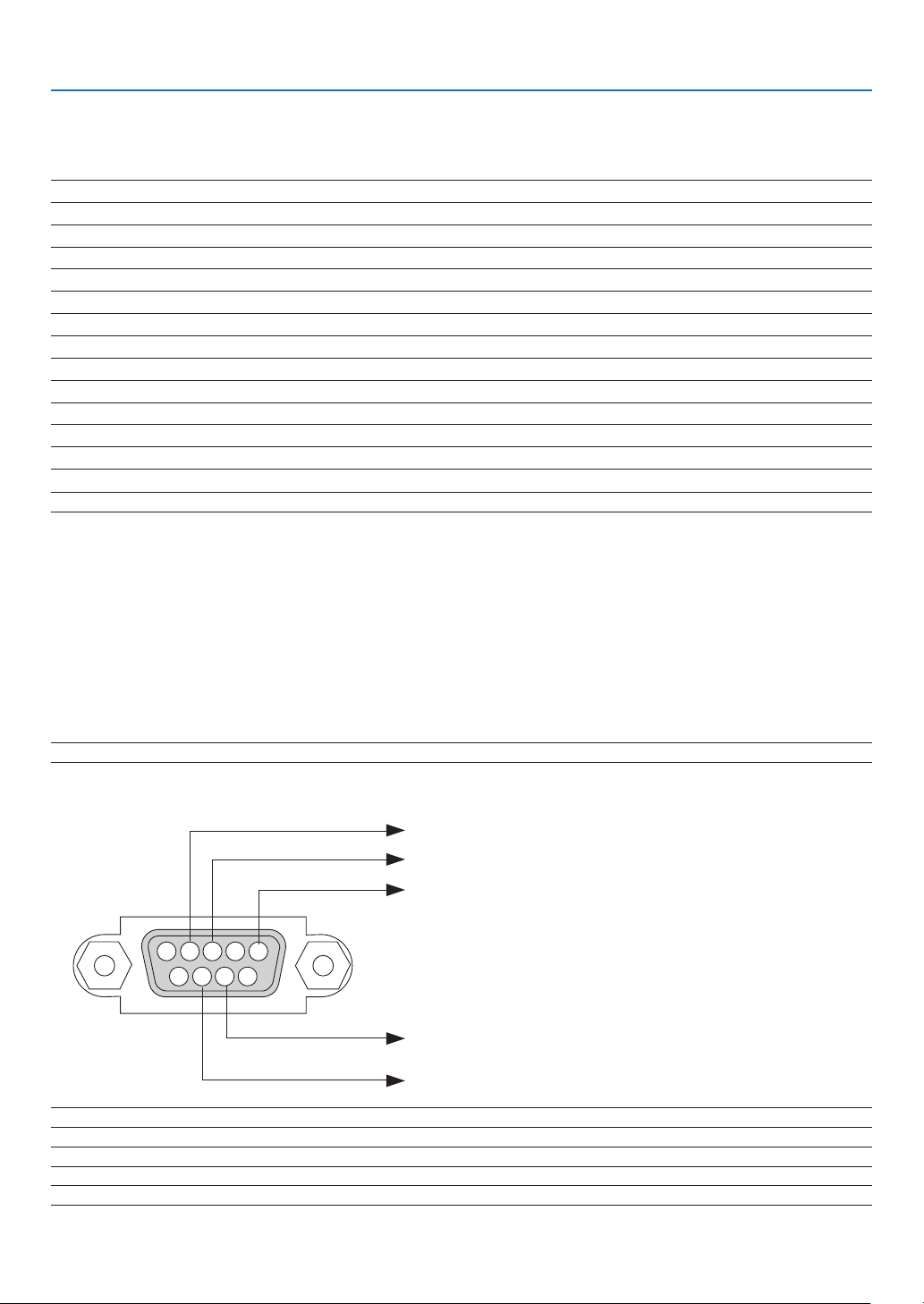
173
9. Appendix
❽ PC Control Codes and Cable Connection
PC Control Codes
Function Code Data
POWER ON 02H 00H 00H 00H 00H 02H
POWER OFF 02H 01H 00H 00H 00H 03H
INPUT SELECT HDMI 02H 03H 00H 00H 02H 01H A1H A9H
INPUT SELECT DisplayPort 02H 03H 00H 00H 02H 01H A6H AEH
INPUT SELECT BNC 02H 03H 00H 00H 02H 01H 02H 0AH
INPUT SELECT BNC(CV) 02H 03H 00H 00H 02H 01H 06H 0EH
INPUT SELECT BNC(Y/C) 02H 03H 00H 00H 02H 01H 0BH 13H
INPUT SELECT COMPUTER 02H 03H 00H 00H 02H 01H 01H 09H
INPUT SELECT HDBaseT 02H 03H 00H 00H 02H 01H 20H 28H
INPUT SELECT SLOT 02H 03H 00H 00H 02H 01H ABH B3H
PICTURE MUTE ON 02H 10H 00H 00H 00H 12H
PICTURE MUTE OFF 02H 11H 00H 00H 00H 13H
NOTE:ContactyourlocaldealerforafulllistofthePCControlCodesifneeded.
Cable Connection
CommunicationProtocol
Baud rate �����������������������������������������38400 bps
Data length
��������������������������������������8 bits
Parity
�����������������������������������������������No parity
Stop bit
��������������������������������������������One bit
X on/off
��������������������������������������������None
Communications procedure
�������������Full duplex
NOTE:Dependingontheequipment,alowerbaudratemayberecommendedforlongcableruns.
PC Control Terminal (D-SUB 9P)
NOTE1:Pins1,4,6and9arenoused.
NOTE2:Jumper“RequesttoSend”and“CleartoSend”togetheronbothendsofthecabletosimplifycableconnection.
NOTE3:Forlongcablerunsitisrecommendedtosetcommunicationspeedwithinprojectormenusto9600bps.
15243
67 98
ToGNDofPC
ToRxDofPC
ToTxDofPC
ToRTSofPC
ToCTSofPC

174
9. Appendix
❾ Troubleshooting Check List
Beforecontactingyourdealerorservicepersonnel,checkthefollowinglisttobesurerepairsareneededalsoby
referringtothe“Troubleshooting”sectioninyouruser’smanual.Thischecklistbelowwillhelpussolveyourproblem
moreefciently.
* Printthispageandthenextpageforyourcheck.
Frequency of occurrence □ always □sometimes(Howoften?_____________________) □other(__________________)
Power
□
No power (POWER indicator does not light blue)� See also “Status
Indicator (STATUS)”�
□
Power cord’s plug is fully inserted into the wall outlet�
□
No power even though you press and hold the POWER button�
□
The main power switch is in the “ON (I)” position�
□
Shut down during operation�
□
Power cord’s plug is fully inserted into the wall outlet�
□
[AUTO POWER OFF] is turned off (only models with the [AUTO
POWER OFF] function)�
□
[OFF TIMER] is turned off (only models with the [OFF TIMER]
function)�
Video and Audio
□
No image is displayed from your PC or video equipment to the
projector�
□
Still no image even though you connect the projector to the PC
first, then start the PC�
□
Enabling your notebook PC’s signal output to the projector�
• Acombinationoffunctionkeyswillenable/disabletheexter-
naldisplay.Usually,thecombinationofthe“Fn”keyalong
with one of the 12 function keys turns the external display
on or off.
□
No image (blue or black background, no display)�
□
Still no image even though you press the AUTO ADJUST button�
□
Still no image even though you carry out [RESET] in the
projector’s menu�
□
Signal cable’s plug is fully inserted into the input terminal
□
A message appears on the screen�
(_____________________________________________)
□
The source connected to the projector is active and available�
□
Still no image even though you adjust the brightness and/or
the contrast�
□
Input source’s resolution and frequency are supported by the
projector�
□
Image is too dark�
□
Remains unchanged even though you adjust the brightness
and/or the contrast�
□
Image is distorted�
□
Image appears to be trapezoidal (unchanged even though you
carry out the [KEYSTONE] adjustment)�
□
Parts of the image are lost�
□
Still unchanged even though you press the AUTO ADJUST
button�
□
Still unchanged even though you carry out [RESET] in the
projector’s menu�
□
Image is shifted in the vertical or horizontal direction�
□
Horizontal and vertical positions are correctly adjusted on a
computer signal�
□
Input source’s resolution and frequency are supported by the
projector�
□
Some pixels are lost�
□
Image is flickering�
□
Still unchanged even though you press the AUTO ADJUST
button�
□
Still unchanged even though you carry out [RESET] in the
projector’s menu�
□
Image shows flickering or color drift on a computer signal�
□
Still unchanged even though you change [FAN MODE] from
[HIGH] to [AUTO]�
□
Image appears blurry or out of focus�
□
Still unchanged even though you checked the signal’s resolution
on PC and changed it to projector’s native resolution�
□
Still unchanged even though you adjusted the focus�
Other
□
Remote control does not work�
□
No obstacles between the sensor of the projector and the
remote control�
□
Projector is placed near a fluorescent light that can disturb the
infrared remote controls�
□
Batteries are new and are not reversed in installation�
□
Buttons on the projector cabinet do not work (only models with the
[CONTROL PANEL LOCK] function)
□
[CONTROL PANEL LOCK] is not turned on or is disabled in
the menu�
□
Still unchanged even though you press and hold the SOURCE
button for a minimum of 10 seconds�
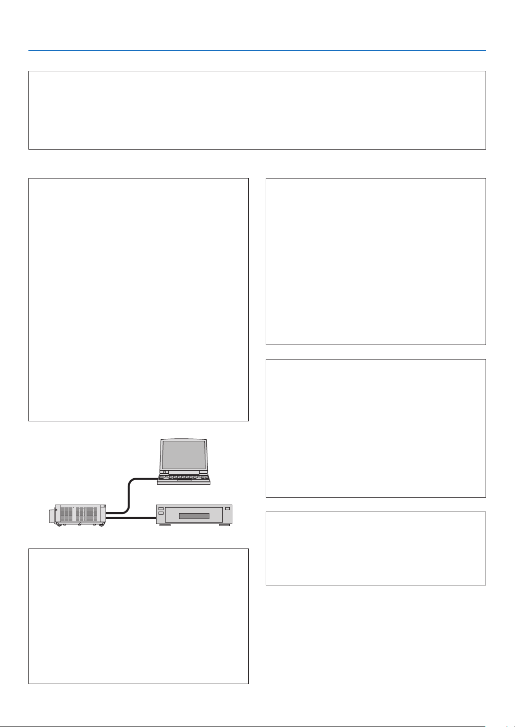
175
9. Appendix
In the space below please describe your problem in detail.
Information on application and environment where your projector is used
Projector
PC
Blu-rayplayer
Projector
Model number:
Serial No�:
Date of purchase:
Light module operating time (hours):
Eco Mode: □ OFF □ ON
Information on input signal:
Horizontal synch frequency [ ] kHz
Vertical synch frequency [ ] Hz
Synch polarity H □ (+) □ (−)
V □ (+) □ (−)
Synch type □ Separate □ Composite
□ Sync on Green
STATUS Indicator:
Steady light □ Orange □ Green
Flashing light [ ] cycles
Remote control model number:
Installation environment
Screen size: inch
Screen type: □ White matte □ Beads □ Polarization
□
Wide angle □ High contrast
Throw distance: feet/inch/m
Orientation: □ Ceiling mount □ Desktop
Power outlet connection:
□
Connected directly to wall outlet
□ Connected to power cord extender or other (the
numberofconnectedequipment______________)
□ Connected to a power cord reel or other (the number
ofconnectedequipment______________)
Computer
Manufacturer:
Model number:
Notebook PC □ / Desktop □
Native resolution:
Refresh rate:
Video adapter:
Other:
Videoequipment
VCR, Blu-ray player, Video camera, Video game or other
Manufacturer:
Model number:
Signal cable
NECstandardorothermanufacturer’scable?
Model number: Length: inch/m
Distribution amplifier
Model number:
Switcher
Model number:
Adapter
Model number:

©NECDisplaySolutions,Ltd.2014 7N952062